mtconnect r standard part 4.1 – cutting tools
TRANSCRIPT

MTConnect R© StandardPart 4.1 – Cutting Tools
Version 1.8.0
Prepared for: MTConnect InstitutePrepared on: September 6, 2021
MTConnect R© is a registered trademark of AMT - The Association for Manufacturing Technology. Use ofMTConnect is limited to use as specified on http://www.mtconnect.org/.

September 6, 2021
MTConnect Specification and Materials
The Association for Manufacturing Technology (AMT) owns the copyright in this MT-Connect Specification or Material. AMT grants to you a non-exclusive, non-transferable,revocable, non-sublicensable, fully-paid-up copyright license to reproduce, copy and re-distribute this MTConnect Specification or Material, provided that you may only copy orredistribute the MTConnect Specification or Material in the form in which you receivedit, without modifications, and with all copyright notices and other notices and disclaimerscontained in the MTConnect Specification or Material.
If you intend to adopt or implement an MTConnect Specification or Material in a product,whether hardware, software or firmware, which complies with an MTConnect Specifi-cation, you shall agree to the MTConnect Specification Implementer License Agreement(“Implementer License”) or to the MTConnect Intellectual Property Policy and Agreement(“IP Policy”). The Implementer License and IP Policy each sets forth the license terms andother terms of use for MTConnect Implementers to adopt or implement the MTConnectSpecifications, including certain license rights covering necessary patent claims for thatpurpose. These materials can be found at www.MTConnect.org, or or by contactingmailto:[email protected].
MTConnect Institute and AMT have no responsibility to identify patents, patent claims orpatent applications which may relate to or be required to implement a Specification, or todetermine the legal validity or scope of any such patent claims brought to their attention.Each MTConnect Implementer is responsible for securing its own licenses or rights to anypatent or other intellectual property rights that may be necessary for such use, and neitherAMT nor MTConnect Institute have any obligation to secure any such rights.
This Material and all MTConnect Specifications and Materials are provided “as is” andMTConnect Institute and AMT, and each of their respective members, officers, affiliates,sponsors and agents, make no representation or warranty of any kind relating to these ma-terials or to any implementation of the MTConnect Specifications or Materials in any prod-uct, including, without limitation, any expressed or implied warranty of noninfringement,merchantability, or fitness for particular purpose, or of the accuracy, reliability, or com-pleteness of information contained herein. In no event shall MTConnect Institute or AMTbe liable to any user or implementer of MTConnect Specifications or Materials for thecost of procuring substitute goods or services, lost profits, loss of use, loss of data or anyincidental, consequential, indirect, special or punitive damages or other direct damages,whether under contract, tort, warranty or otherwise, arising in any way out of access, useor inability to use the MTConnect Specification or other MTConnect Materials, whetheror not they had advance notice of the possibility of such damage.
MTConnect Part 4.1: Cutting Tools - Version 1.8.0 i
Table of Contents1 Purpose of This Document 2
2 Terminology and Conventions 32.1 Glossary . . . . . . . . . . . . . . . . . . . . . . . . . . . . . . . . . . . 32.2 Acronyms . . . . . . . . . . . . . . . . . . . . . . . . . . . . . . . . . . 92.3 MTConnect References . . . . . . . . . . . . . . . . . . . . . . . . . . . 9
3 Cutting Tool and Cutting Tool Archetype 103.1 XML Schema Structure for CuttingTool and CuttingToolArchetype . . . . 103.2 Common Attributes for CuttingTool and CuttingToolArchetype . . . . . . 123.3 Common Elements for CuttingTool and CuttingToolArchetype . . . . . . 14
3.3.1 Description Element for CuttingTool and CuttingToolArchetype . 14
4 CuttingToolArchetype Information Model 154.1 Attributes for CuttingToolArchetype . . . . . . . . . . . . . . . . . . . . 194.2 Elements for CuttingToolArchetype . . . . . . . . . . . . . . . . . . . . 19
4.2.1 CuttingToolDefinition Element for CuttingToolArchetype . . . . . 204.2.1.1 Attributes for CuttingToolDefinition . . . . . . . . . . . 20
4.2.1.1.1 format Attribute for CuttingToolDefnition . . 204.2.1.2 Elements for CuttingToolDefinition . . . . . . . . . . . 214.2.1.3 ISO13399 Standard . . . . . . . . . . . . . . . . . . . 21
4.2.2 CuttingToolLifeCycle Element for CuttingToolArchetype . . . . . 21
5 CuttingTool Information model 225.1 Attributes for CuttingTool . . . . . . . . . . . . . . . . . . . . . . . . . . 225.2 Elements for CuttingTool . . . . . . . . . . . . . . . . . . . . . . . . . . 22
5.2.1 CuttingToolLifeCycle Elements for CuttingTool Only . . . . . . . 235.2.1.1 CutterStatus Element for CuttingToolLifeCycle . . . . . 23
5.2.1.1.1 Status Element for CutterStatus . . . . . . . . 245.2.1.2 ToolLife Element for CuttingToolLifeCycle . . . . . . . 26
5.2.1.2.1 Attributes for ToolLife . . . . . . . . . . . . . 275.2.1.2.2 type Attribute for ToolLife . . . . . . . . . . . 275.2.1.2.3 countDirection Attribute for ToolLife . . . . . 28
5.2.1.3 Location Element for CuttingToolLifeCycle . . . . . . . 285.2.1.3.1 Attributes for Location . . . . . . . . . . . . . 295.2.1.3.2 type Attribute for Location . . . . . . . . . . . 315.2.1.3.3 postiveOverlap Attribute for Location . . . . . 315.2.1.3.4 negativeOverlap Attribute for Location . . . . 31
5.2.1.4 ReconditionCount Element for CuttingToolLifeCycle . 325.2.1.4.1 Attributes for ReconditionCount . . . . . . . . 32
5.2.2 CuttingToolArchetypeReference Element for Cutting Tool . . . . 33
ii
September 6, 2021
5.2.2.1 source Attribute for CuttingToolArcheTypeReference . 33
6 Common Entity CuttingToolLifeCycle 346.1 CuttingToolLifeCycle . . . . . . . . . . . . . . . . . . . . . . . . . . . . 34
6.1.1 XML Schema Structure for CuttingToolLifeCycle . . . . . . . . . 346.2 Elements for CuttingToolLifeCycle . . . . . . . . . . . . . . . . . . . . . 36
6.2.1 ProgramToolGroup Element for CuttingToolLifeCycle . . . . . . 376.2.2 ProgramToolNumber Element for CuttingToolLifeCycle . . . . . 376.2.3 ProcessSpindleSpeed Element for CuttingToolLifeCycle . . . . . 38
6.2.3.1 Attributes for ProcessSpindleSpeed . . . . . . . . . . . 386.2.4 ProcessFeedRate Element for CuttingToolLifeCycle . . . . . . . . 39
6.2.4.1 Attributes for ProcessFeedRate . . . . . . . . . . . . . 396.2.5 ConnectionCodeMachineSide Element for CuttingToolLifeCycle . 406.2.6 xs:any Element for CuttingToolLifeCycle . . . . . . . . . . . . . 406.2.7 Measurements Element for CuttingToolLifeCycle . . . . . . . . . 406.2.8 Measurement . . . . . . . . . . . . . . . . . . . . . . . . . . . . 41
6.2.8.1 Attributes for Measurement . . . . . . . . . . . . . . . 426.2.8.2 Measurement Subtypes for CuttingToolLifeCycle . . . . 43
6.2.9 CuttingItems Element for CuttingToolLifeCycle . . . . . . . . . . 476.2.9.1 Attributes for CuttingItems . . . . . . . . . . . . . . . . 48
6.2.10 CuttingItem . . . . . . . . . . . . . . . . . . . . . . . . . . . . . 486.2.10.1 Attributes for CuttingItem . . . . . . . . . . . . . . . . 50
6.2.10.1.1 indices Attribute for CuttingItem . . . . . . . 506.2.10.1.2 itemId Attribute for CuttingItem . . . . . . . . 506.2.10.1.3 manufacturers Attribute for CuttingItem . . . . 506.2.10.1.4 grade Attribute for CuttingItem . . . . . . . . 51
6.2.10.2 Elements for CuttingItem . . . . . . . . . . . . . . . . 516.2.10.2.1 Description Element for CuttingItem . . . . . 516.2.10.2.2 Locus Element for CuttingItem . . . . . . . . 526.2.10.2.3 ItemLife Element for CuttingItem . . . . . . . 536.2.10.2.4 Attributes for ItemLife . . . . . . . . . . . . . 546.2.10.2.5 type Attribute for ItemLife . . . . . . . . . . . 546.2.10.2.6 countDirection Attribute for ItemLife . . . . . 55
6.2.10.3 Measurement Subtypes for CuttingItem . . . . . . . . . 55
Appendices 62A Bibliography . . . . . . . . . . . . . . . . . . . . . . . . . . . . . . . . . 62B Additional Illustrations . . . . . . . . . . . . . . . . . . . . . . . . . . . 64C Cutting Tool Example . . . . . . . . . . . . . . . . . . . . . . . . . . . . 68
C.1 Shell Mill . . . . . . . . . . . . . . . . . . . . . . . . . . . . . . 68C.2 Step Drill . . . . . . . . . . . . . . . . . . . . . . . . . . . . . . 71C.3 Shell Mill with Individual Loci . . . . . . . . . . . . . . . . . . . 73
MTConnect Part 4.1: Cutting Tools - Version 1.8.0 iii
September 6, 2021
C.4 Drill with Individual Loci . . . . . . . . . . . . . . . . . . . . . . 75C.5 Shell Mill with Different Inserts on First Row . . . . . . . . . . . 77
MTConnect Part 4.1: Cutting Tools - Version 1.8.0 iv
September 6, 2021
Table of FiguresFigure 1: Cutting Tool Schema . . . . . . . . . . . . . . . . . . . . . . . . . . . 11Figure 2: Cutting Tool Parts . . . . . . . . . . . . . . . . . . . . . . . . . . . . 15Figure 3: Cutting Tool Composition . . . . . . . . . . . . . . . . . . . . . . . . 16Figure 4: Cutting Tool, Tool Item, and Cutting Item . . . . . . . . . . . . . . . 17Figure 5: Cutting Tool, Tool Item, and Cutting Item 2 . . . . . . . . . . . . . . 17Figure 6: Cutting Tool Measurements . . . . . . . . . . . . . . . . . . . . . . . 18Figure 7: Cutting Tool Asset Structure . . . . . . . . . . . . . . . . . . . . . . 18Figure 8: CuttingToolDefinition Schema . . . . . . . . . . . . . . . . . . . . . . 20Figure 9: CutterStatus Schema . . . . . . . . . . . . . . . . . . . . . . . . . . . 23Figure 10:ToolLife Schema . . . . . . . . . . . . . . . . . . . . . . . . . . . . . 26Figure 11:Location Schema . . . . . . . . . . . . . . . . . . . . . . . . . . . . . 29Figure 12:ReconditionCount Schema . . . . . . . . . . . . . . . . . . . . . . . . 32Figure 13:CuttingToolArcheTypeReference Schema . . . . . . . . . . . . . . . 33Figure 14:CuttingToolLifeCycle Schema . . . . . . . . . . . . . . . . . . . . . . 35Figure 15:ProcessSpindleSpeed Schema . . . . . . . . . . . . . . . . . . . . . . 38Figure 16:ProcessFeedRate Schema . . . . . . . . . . . . . . . . . . . . . . . . 39Figure 17:Measurement Schema . . . . . . . . . . . . . . . . . . . . . . . . . . 41Figure 18:Cutting Tool Measurement Diagram 1 . . . . . . . . . . . . . . . . . 43Figure 19:Cutting Tool Measurement Diagram 2 . . . . . . . . . . . . . . . . . 44Figure 20:CuttingItems Schema . . . . . . . . . . . . . . . . . . . . . . . . . . . 47Figure 21:CuttingItem Schema . . . . . . . . . . . . . . . . . . . . . . . . . . . 49Figure 22:ItemLife Schema . . . . . . . . . . . . . . . . . . . . . . . . . . . . . 53Figure 23:Cutting Tool . . . . . . . . . . . . . . . . . . . . . . . . . . . . . . . . 56Figure 24:Cutting Item . . . . . . . . . . . . . . . . . . . . . . . . . . . . . . . 56Figure 25:Cutting Item Measurement Diagram 3 . . . . . . . . . . . . . . . . . 57Figure 26:Cutting Item Drive Angle . . . . . . . . . . . . . . . . . . . . . . . . 57Figure 27:Cutting Tool Measurement Diagram 1 (Cutting Tool, Cutting Item,
and Assembly Item – ISO 13399) . . . . . . . . . . . . . . . . . . . . 64Figure 28:Cutting Tool Measurement Diagram 2 (Cutting Tool, Cutting Item,
and Assembly Item – ISO 13399) . . . . . . . . . . . . . . . . . . . . 65Figure 29:Cutting Tool Measurement Diagram 3 (Cutting Item – ISO 13399) . 65Figure 30:Cutting Tool Measurement Diagram 4 (Cutting Item – ISO 13399) . 66Figure 31:Cutting Tool Measurement Diagram 5 (Cutting Item – ISO 13399) . 66Figure 32:Cutting Tool Measurement Diagram 6 (Cutting Item – ISO 13399) . 67Figure 33:Shell Mill Side View . . . . . . . . . . . . . . . . . . . . . . . . . . . 68Figure 34:Indexable Insert Measurements . . . . . . . . . . . . . . . . . . . . . 68Figure 35:Step Mill Side View . . . . . . . . . . . . . . . . . . . . . . . . . . . . 71Figure 36:Shell Mill with Explicate Loci . . . . . . . . . . . . . . . . . . . . . . 73Figure 37:Step Drill with Explicate Loci . . . . . . . . . . . . . . . . . . . . . . 75Figure 38:Shell Mill with Different Inserts on First Row . . . . . . . . . . . . . 77
MTConnect Part 4.1: Cutting Tools - Version 1.8.0 v
List of TablesTable 1: Attributes for CuttingTool and CuttingToolArchetype . . . . . . . . . 12Table 2: Common Elements for CuttingTool and CuttingToolArchetype . . . . 14Table 3: Elements for CuttingToolArchetype . . . . . . . . . . . . . . . . . . . 19Table 4: Attributes for CuttingToolDefinition . . . . . . . . . . . . . . . . . . . 20Table 5: Values for format attribute of CuttingToolDefinition . . . . . . . . . . 21Table 6: Elements for CuttingTool . . . . . . . . . . . . . . . . . . . . . . . . . 22Table 7: Elements for CutterStatus . . . . . . . . . . . . . . . . . . . . . . . . 24Table 8: Values for Status Element of CutterStatus . . . . . . . . . . . . . . . 24Table 9: Attributes for ToolLife . . . . . . . . . . . . . . . . . . . . . . . . . . 27Table 10:Values for type of ToolLife . . . . . . . . . . . . . . . . . . . . . . . . 28Table 11:Values for countDirection . . . . . . . . . . . . . . . . . . . . . . . . . 28Table 12:Attributes for Location . . . . . . . . . . . . . . . . . . . . . . . . . . 30Table 13:Values for type of Location . . . . . . . . . . . . . . . . . . . . . . . . 31Table 14:Attributes for ReconditionCount . . . . . . . . . . . . . . . . . . . . . 32Table 15:Attributes for CuttingToolArchetypeReference . . . . . . . . . . . . . 33Table 16:Elements for CuttingToolLifeCycle . . . . . . . . . . . . . . . . . . . 36Table 17:Attributes for ProcessSpindleSpeed . . . . . . . . . . . . . . . . . . . 38Table 18:Attributes for ProcessFeedRate . . . . . . . . . . . . . . . . . . . . . 39Table 19:Attributes for Measurement . . . . . . . . . . . . . . . . . . . . . . . 42Table 20:Measurement Subtypes for CuttingTool . . . . . . . . . . . . . . . . . 44Table 21:Attributes for CuttingItems . . . . . . . . . . . . . . . . . . . . . . . 48Table 22:Attributes for CuttingItem . . . . . . . . . . . . . . . . . . . . . . . . 50Table 23:Elements for CuttingItem . . . . . . . . . . . . . . . . . . . . . . . . . 51Table 24:Attributes for ItemLife . . . . . . . . . . . . . . . . . . . . . . . . . . 54Table 25:Values for type of ItemLife . . . . . . . . . . . . . . . . . . . . . . . . 55Table 26:Values for countDirection . . . . . . . . . . . . . . . . . . . . . . . . . 55Table 27:Measurement Subtypes for CuttingItem . . . . . . . . . . . . . . . . 57
1
September 6, 2021
1 Purpose of This Document1
This document, MTConnect Standard: Part 4.1 - Cutting Tools of the MTConnect Stan-2
dard, establishes the rules and terminology to be used by designers to describe the function3
and operation of cutting tools used within manufacturing and to define the data that is pro-4
vided by an Agent from a piece of equipment. This part of the Standard also defines the5
structure for the XML document that is returned from an Agent in response to a probe6
request.7
The data associated with these cutting tools will be retrieved from multiple sources that8
are responsible for providing their knowledge of an MTConnect Asset.9
MTConnect Part 4.1: Cutting Tools - Version 1.8.0 2

September 6, 2021
2 Terminology and Conventions10
Refer to Section 2 of MTConnect Standard Part 1.0 - Overview and Fundamentals for a11
dictionary of terms, reserved language, and document conventions used in the MTConnect12
Standard.13
2.1 Glossary14
CDATA15
General meaning:16
An abbreviation for Character Data.17
CDATA is used to describe a value (text or data) published as part of an XML ele-18
ment.19
For example, "This is some text" is the CDATA in the XML element:20
<Message ...>This is some text</Message>21
Appears in the documents in the following form: CDATA22
NMTOKEN23
The data type for XML identifiers.24
Note: The identifier must start with a letter, an underscore "_" or a colon. The next25
character must be a letter, a number, or one of the following ".", "-", "_", ":". The26
identifier must not have any spaces or special characters.27
Appears in the documents in the following form: NMTOKEN.28
XML29
Stands for eXtensible Markup Language.30
XML defines a set of rules for encoding documents that both a human-readable and31
machine-readable.32
XML is the language used for all code examples in the MTConnect Standard.33
Refer to http://www.w3.org/XML for more information about XML.34
Agent35
Refers to an MTConnect Agent.36
Software that collects data published from one or more piece(s) of equipment, orga-37
nizes that data in a structured manner, and responds to requests for data from client38
MTConnect Part 4.1: Cutting Tools - Version 1.8.0 3

September 6, 2021
software systems by providing a structured response in the form of a Response Doc-39
ument that is constructed using the semantic data models defined in the Standard.40
Appears in the documents in the following form: Agent.41
Asset42
item, thing or entity that has potential or actual value to an organization Ref:ISO43
55000:2014(en)44
Note 1 to entry: Value can be tangible or intangible, financial or non-financial,45
and includes consideration of risks and liabilities. It can be positive or negative46
at different stages of the asset life.47
Note 2 to entry: Physical assets usually refer to equipment, inventory and prop-48
erties owned by the organization. Physical assets are the opposite of intangible49
assets, which are non-physical assets such as leases, brands, digital assets, use50
rights, licences, intellectual property rights, reputation or agreements.51
Note 3 to entry: A grouping of assets referred to as an asset system could also52
be considered as an asset.53
54
Attribute55
A term that is used to provide additional information or properties for an element.56
Appears in the documents in the following form: attribute.57
Child Element58
A portion of a data modeling structure that illustrates the relationship between an59
element and the higher-level Parent Element within which it is contained.60
Appears in the documents in the following form: Child Element.61
Component62
General meaning:63
A Structural Element that represents a physical or logical part or subpart of a piece64
of equipment.65
Appears in the documents in the following form: Component.66
Used in Information Models:67
A data modeling element used to organize the data being retrieved from a piece of68
equipment.69
MTConnect Part 4.1: Cutting Tools - Version 1.8.0 4

September 6, 2021
• When used as an XML container to organize Lower Level Component ele-70
ments.71
Appears in the documents in the following form: Components.72
• When used as an abstract XML element. Component is replaced in a data73
model by a type of Component element. Component is also an XML con-74
tainer used to organize Lower Level Component elements, Data Entities, or75
both.76
Appears in the documents in the following form: Component.77
Current Request78
A Current Request is a Request to an Agent to produce an MTConnectStreams Re-79
sponse Document containing the Observations Information Model for a snapshot of80
the latest observations at the moment of the Request or at a given sequence number.81
Data Entity82
A primary data modeling element that represents all elements that either describe83
data items that may be reported by an Agent or the data items that contain the actual84
data published by an Agent.85
Appears in the documents in the following form: Data Entity.86
Devices Information Model87
A set of rules and terms that describes the physical and logical configuration for a88
piece of equipment and the data that may be reported by that equipment.89
Appears in the documents in the following form: Devices Information Model.90
Equipment Metadata91
See Metadata92
Information Model93
The rules, relationships, and terminology that are used to define how information is94
structured.95
For example, an information model is used to define the structure for each MTCon-96
nect Response Document; the definition of each piece of information within those97
documents and the relationship between pieces of information.98
Appears in the documents in the following form: Information Model.99
Lower Level100
A nested element that is below a higher level element.101
MTConnect Part 4.1: Cutting Tools - Version 1.8.0 5
September 6, 2021
Metadata102
Data that provides information about other data.103
For example, Equipment Metadata defines both the Structural Elements that rep-104
resent the physical and logical parts and sub-parts of each piece of equipment, the105
relationships between those parts and sub-parts, and the definitions of the Data En-106
tities associated with that piece of equipment.107
Appears in the documents in the following form: Metadata or Equipment Metadata.108
MTConnect Agent109
See definition for Agent.110
MTConnect Asset111
An MTConnect Asset is an Asset used by the manufacturing process to perform112
tasks.113
Note 1 to entry: An MTConnect Asset relies upon an MTConnect Device to114
provide observations and information about itself and the MTConnect Device115
revises the information to reflect changes to the MTConnect Asset during their116
interaction. Examples of MTConnect Assets are Cutting Tools, Part Information,117
Manufacturing Processes, Fixtures, and Files.118
Note 2 to entry: A singular assetId uniquely identifies an MTConnect Asset119
throughout its lifecycle and is used to track and relate the MTConnect Asset to120
other MTConnect Devices and entities.121
Note 3 to entry: MTConnect Assets are temporally associated with a device and122
can be removed from the device without damage or alteration to its primary123
functions.124
125
MTConnect Device126
An MTConnect Device is a piece of equipment or a manufacturing system that pro-127
duces observations about itself and/or publishes data using the MTConnect Infor-128
mation Model.129
MTConnect Information Model130
See Information Model131
MTConnectDevices Response Document132
A Response Document published by an MTConnect Agent in response to a Probe133
Request.134
MTConnect Part 4.1: Cutting Tools - Version 1.8.0 6

September 6, 2021
MTConnectStreams Response Document135
A Response Document published by an MTConnect Agent in response to a Current136
Request or a Sample Request.137
observation138
The observed value of a property at a point in time.139
Observations Information Model140
An Information Model that describes the Streaming Data reported by a piece of141
equipment.142
Parent Element143
An XML element used to organize Lower Level child elements that share a common144
relationship to the Parent Element.145
Appears in the documents in the following form: Parent Element.146
Probe Request147
A Probe Request is a Request to an Agent to produce an MTConnectDevices Re-148
sponse Document containing the Devices Information Model.149
Request150
A communications method where a client software application transmits a message151
to an Agent. That message instructs the Agent to respond with specific information.152
Appears in the documents in the following form: Request.153
Response Document154
An electronic document published by an MTConnect Agent in response to a Probe155
Request, Current Request, Sample Request or Asset Request.156
Sample Request157
A Sample Request is a Request to an Agent to produce an MTConnectStreams Re-158
sponse Document containing the Observations Information Model for a set of time-159
stamped observations made by Components.160
semantic data model161
A methodology for defining the structure and meaning for data in a specific logical162
way.163
It provides the rules for encoding electronic information such that it can be inter-164
preted by a software system.165
Appears in the documents in the following form: semantic data model.166
MTConnect Part 4.1: Cutting Tools - Version 1.8.0 7

September 6, 2021
sequence number167
The primary key identifier used to manage and locate a specific piece of Streaming168
Data in an Agent.169
sequence number is a monotonically increasing number within an instance of an170
Agent.171
Appears in the documents in the following form: sequence number.172
Spindle173
A mechanism that provides rotational capabilities to a piece of equipment.174
Typically used for either work holding, materials or cutting tools.175
Streaming Data176
The values published by a piece of equipment for the Data Entities defined by the177
Equipment Metadata.178
Appears in the documents in the following form: Streaming Data.179
Structural Element180
General meaning:181
An XML element that organizes information that represents the physical and logical182
parts and sub-parts of a piece of equipment.183
Appears in the documents in the following form: Structural Element.184
Used to indicate hierarchy of Components:185
When used to describe a primary physical or logical construct within a piece of186
equipment.187
Appears in the documents in the following form: Top Level Structural Element.188
When used to indicate a Child Element which provides additional detail describing189
the physical or logical structure of a Top Level Structural Element.190
Appears in the documents in the following form: Lower Level Structural Element.191
Top Level192
Structural Elements that represent the most significant physical or logical functions193
of a piece of equipment.194
Valid Data Value195
One or more acceptable values or constrained values that can be reported for a Data196
Entity.197
Appears in the documents in the following form: Valid Data Value(s).198
MTConnect Part 4.1: Cutting Tools - Version 1.8.0 8

September 6, 2021
XML Schema199
In the MTConnect Standard, an instantiation of a schema defining a specific docu-200
ment encoded in XML.201
2.2 Acronyms202
AMT203
The Association for Manufacturing Technology204
2.3 MTConnect References205
[MTConnect Part 1.0] MTConnect Standard Part 1.0 - Overview and Fundamentals. Ver-206
sion 1.8.0.207
[MTConnect Part 2.0] MTConnect Standard: Part 2.0 - Devices Information Model. Ver-208
sion 1.8.0.209
[MTConnect Part 3.0] MTConnect Standard: Part 3.0 - Streams Information Model. Ver-210
sion 1.8.0.211
[MTConnect Part 4.1] MTConnect Standard: Part 4.1 - Cutting Tools. Version 1.8.0.212
MTConnect Part 4.1: Cutting Tools - Version 1.8.0 9

September 6, 2021
3 Cutting Tool and Cutting Tool Archetype213
There are two Information Models used to represent a cutting tool, CuttingToolArchetype214
and CuttingTool. The CuttingToolArchetype represent the static cutting tool215
geometries and nominal values as one would expect from a tool catalog and the Cut-216
tingTool represents the use or application of the tool on the shop floor with actual217
measured values and process data. In Version 1.3.0 of the MTConnect Standard it was de-218
cided to separate out these two concerns since not all pieces of equipment will have access219
to both sets of information. In this way, a generic definition of the cutting tool can coexist220
with a specific assembly Information Model with minimal redundancy of data.221
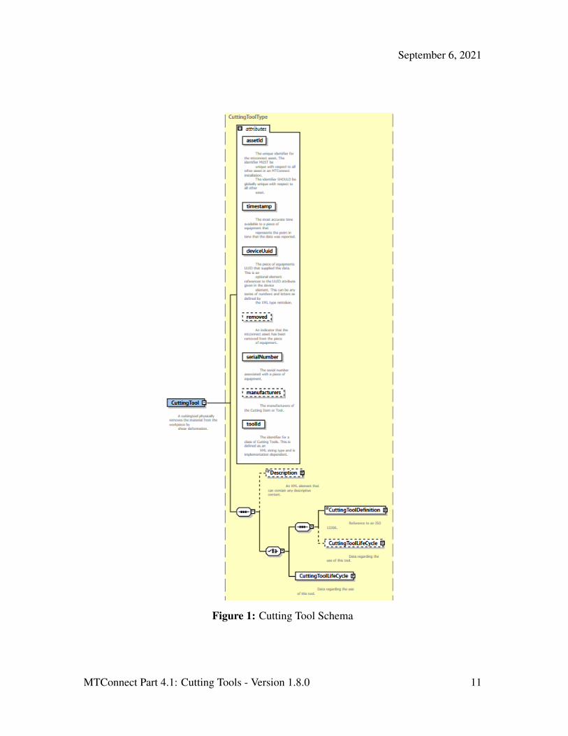
3.1 XML Schema Structure for CuttingTool and CuttingToolArchetype222
The Figure 1 shows the XML Schema that applies to both the CuttingTool Information223
Model and the CuttingToolArchetype Information Model.224
MTConnect Part 4.1: Cutting Tools - Version 1.8.0 10
September 6, 2021
Figure 1: Cutting Tool Schema
MTConnect Part 4.1: Cutting Tools - Version 1.8.0 11

September 6, 2021
Note: The use of the XML element CuttingToolDefinition has been DEP-225
RECATED in the CuttingTool schema, but remains in the Cutting-226
ToolArchetype schema.227
The following sections contain the definitions of CuttingTool and CuttingToolArchetype228
and describe their unique components. The following are the common entities for both el-229
ements.230
3.2 Common Attributes for CuttingTool and CuttingToolArchetype231
Table 1: Attributes for CuttingTool and CuttingToolArchetype
Attribute Description Occurrence
timestamp The time this MTConnect Asset was lastmodified. Always given in UTC. Thetimestamp MUST be provided in UTC(Universal Time Coordinate, also known asGMT). This is the time the Asset data was lastmodified.
timestamp is a required attribute.
1
assetId The unique identifier of the instance of this tool.This will be the same as the toolId andserialNumber in most cases. The assetIdSHOULD be the combination of the toolIdand serialNumber as in toolId.serialNumber or an equivalentimplementation dependent identification scheme.
assetId is a required attribute.
assetId is a permanent identifier that will beassociated with an MTConnect Asset for its entirelife.
1
serialNumber The unique identifier for this assembly. This isdefined as an XML string type and isimplementation dependent.
serialNumber is a required attribute.
1
MTConnect Part 4.1: Cutting Tools - Version 1.8.0 12

September 6, 2021
Continuation of Table 1
Attribute Description Occurrence
toolId The identifier for a class of Cutting Tools. This isdefined as an XML string type and isimplementation dependent.
toolId is a required attribute.
1
deviceUuid A reference to the Device’s uuid that createdthe Asset information. The deviceUuidMUST be an NMTOKEN XML type.
1
manufacturers An optional attribute referring to themanufacturer(s) of this Cutting Tool, for thiselement, this will reference the Tool Item andAdaptive Items specifically. The Cutting Itemsmanufacturers’ will be an attribute of theCuttingItem elements. The representationwill be a comma (,) delimited list of manufacturernames. This can be any series of numbers andletters as defined by the XML type string.
0..1
removed This is an indicator that the Cutting Tool has beenremoved from the piece of equipment.
removed is a required attribute.
If the MTConnect Asset is marked as removed, itwill not be visible to the client application unlessthe includeRemoved=true parameter isprovided in the URL. If this attribute is notpresent it MUST be assumed to be false. Thevalue is an xsi:boolean type and MUST betrue or false.
0..1
MTConnect Part 4.1: Cutting Tools - Version 1.8.0 13

September 6, 2021
3.3 Common Elements for CuttingTool and CuttingToolArchetype232
Table 2: Common Elements for CuttingTool and CuttingToolArchetype
Element Description Occurrence
Description An element that can contain any descriptive content.This can contain configuration information andmanufacturer specific details. This element isdefined to contain mixed content and XMLelements can be added to extend the descriptivesemantics of MTConnect Standard.
0..1
3.3.1 Description Element for CuttingTool and CuttingToolArchetype233
Description MAY contain mixed content, meaning that an additional XML element234
or plain text may be provided as part of the content of the description tag. Currently235
Description contains no attributes.236
MTConnect Part 4.1: Cutting Tools - Version 1.8.0 14

September 6, 2021
4 CuttingToolArchetype Information Model237
The CuttingToolArchetype Information Model will have the identical structure as238
the CuttingTool Information Model illustrated in Figure 1 , except for a few entities.239
The CuttingTool will no longer carry the CuttingToolDefinition, this MUST240
only appear in the CuttingToolArchetype. The CuttingToolArchetypeMUST241
NOT have measured values and MUST NOT have any of the following items: Cutter-242
Status, ToolLife values, Location, or a ReconditionCount.243
MTConnect Standard will adopt the ISO 13399 structure when formulating the vocabulary244
for Cutting Tool geometries and structure to be represented in the CuttingToolArchetype.245
The nominal values provided in the CuttingToolLifeCycle section are only con-246
cerned with two aspects of the Cutting Tool, the Cutting Tool and the Cutting Item. The247
Tool Item, Adaptive Item, and Assembly Item will only be covered in the Cutting-248
ToolDefinition section of this document since this section contains the full ISO249
13399 information about a Cutting Tool.250
Figure 2: Cutting Tool Parts
The Figure 2 illustrates the parts of a Cutting Tool. The Cutting Tool is the aggregate of251
all the components and the Cutting Item is the part of the tool that removes the material252
from the workpiece. These are the primary focus of the MTConnect Standard.253
MTConnect Part 4.1: Cutting Tools - Version 1.8.0 15

September 6, 2021
Figure 3: Cutting Tool Composition
Figure 3 provides another view of the composition of a Cutting Tool. The Adaptive Items254
and Tool Items will be used for measurements, but will not be modeled as separate entities.255
When we are referencing the Cutting Tool we are referring to the entirety of the assembly256
and when we provide data regarding the Cutting Item we are referencing each individual257
item as illustrated on the left of the previous diagram.258
Figure 4 and Figure 5 further illustrates the components of the Cutting Tool. As we259
compose the Tool Item, Cutting Item, Adaptive Item, we get a Cutting Tool. The Tool Item,260
Adaptive Item, and Assembly Item will only be in the CuttingToolDefinition261
section that will contain the full ISO 13399 information.262
MTConnect Part 4.1: Cutting Tools - Version 1.8.0 16

September 6, 2021
Figure 4: Cutting Tool, Tool Item, and Cutting Item
Figure 5: Cutting Tool, Tool Item, and Cutting Item 2
MTConnect Part 4.1: Cutting Tools - Version 1.8.0 17

September 6, 2021
Figure 4 and Figure 5 use the ISO 13399 codes for each of the measurements. These263
codes will be translated into the MTConnect Standard vocabulary as illustrated below.264
The measurements will have a maximum, minimum, and nominal value representing the265
tolerance of allowable values for this dimension. See below for a full discussion.266
Figure 6: Cutting Tool Measurements
The MTConnect Standard will not define the entire geometry of the Cutting Tool, but will267
provide the information necessary to use the tool in the manufacturing process. Addi-268
tional information can be added to the definition of the Cutting Tool by means of schema269
extensions.270
Additional diagrams will reference these dimensions by their codes that will be defined in271
the measurement tables. The codes are consistent with the codes used in ISO 13399 and272
have been standardized. MTConnect Standard will use the full text name for clarity in the273
XML document.274
Figure 7: Cutting Tool Asset Structure
The structure of the MTConnectAssets header is defined in MTConnect Standard Part275
1.0 - Overview and Fundamentals of the Standard. A finite number of MTConnect Assets276
will be stored in the Agent. This finite number is implementation specific and will depend277
on memory and storage constraints. The standard will not prescribe the number or capacity278
requirements for an implementation.279
MTConnect Part 4.1: Cutting Tools - Version 1.8.0 18
September 6, 2021
4.1 Attributes for CuttingToolArchetype280
Refer to Section 3.2 - Common Attributes for CuttingTool and CuttingToolArchetype for a281
full description of the attributes for CuttingToolArchetype Information Model.282
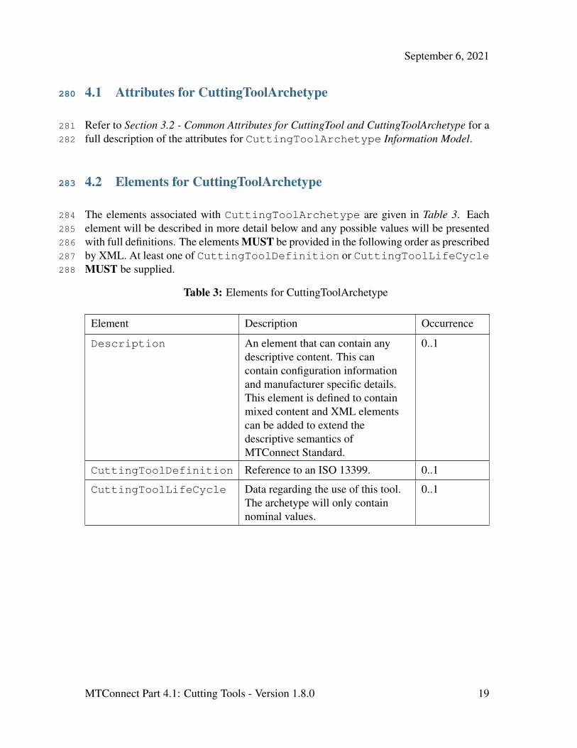
4.2 Elements for CuttingToolArchetype283
The elements associated with CuttingToolArchetype are given in Table 3. Each284
element will be described in more detail below and any possible values will be presented285
with full definitions. The elements MUST be provided in the following order as prescribed286
by XML. At least one of CuttingToolDefinition or CuttingToolLifeCycle287
MUST be supplied.288
Table 3: Elements for CuttingToolArchetype
Element Description Occurrence
Description An element that can contain anydescriptive content. This cancontain configuration informationand manufacturer specific details.This element is defined to containmixed content and XML elementscan be added to extend thedescriptive semantics ofMTConnect Standard.
0..1
CuttingToolDefinition Reference to an ISO 13399. 0..1
CuttingToolLifeCycle Data regarding the use of this tool.The archetype will only containnominal values.
0..1
MTConnect Part 4.1: Cutting Tools - Version 1.8.0 19

September 6, 2021
4.2.1 CuttingToolDefinition Element for CuttingToolArchetype289
Figure 8: CuttingToolDefinition Schema
The CuttingToolDefinition contains the detailed structure of the Cutting Tool.290
The information contained in this element will be static during its lifecycle. Currently we291
are referring to the external ISO 13399 standard to provide the complete definition and292
composition of the Cutting Tool as defined in Section 6.1 - CuttingToolLifeCycle.293
4.2.1.1 Attributes for CuttingToolDefinition294
Table 4: Attributes for CuttingToolDefinition
Attribute Description Occurrence
format Identifies the expected representation of the enclosed data.
format is an optional attribute.
Valid values of format are – XML, EXPRESS, TEXT, orUNDEFINED.
If format is not specified, the assumed format is XML.
0..1
4.2.1.1.1 format Attribute for CuttingToolDefnition295
The format attribute describes the expected representation of the enclosed data. If no296
value is given, the assumed format will be XML.297
MTConnect Part 4.1: Cutting Tools - Version 1.8.0 20

September 6, 2021
Table 5: Values for format attribute of CuttingToolDefinition
Value Description
XML The default value for the definition. The content will be an XMLdocument.
EXPRESS The document will confirm to the ISO 10303 Part 21 standard.
TEXT The document will be a text representation of the tool data.
UNDEFINED The document will be provided in an undefined format.
4.2.1.2 Elements for CuttingToolDefinition298
The only acceptable Cutting Tool definition at present is defined by the ISO 13399 stan-299
dard. Additional formats MAY be considered in the future.300
4.2.1.3 ISO13399 Standard301
The ISO 13399 data MUST be presented in either XML (ISO 10303-28) or EXPRESS302
format (ISO 10303-21). An XML Schema will be preferred as this will allow for easier303
integration with the MTConnect Standard XML tools. EXPRESS will also be supported,304
but software tools will need to be provided or made available for handling this data repre-305
sentation.306
There will be the root element of the ISO13399 document when XML is used. When307
EXPRESS is used the XML element will be replaced by the text representation.308
4.2.2 CuttingToolLifeCycle Element for CuttingToolArchetype309
Refer to Section 6 - Common Entity CuttingToolLifeCycle for a complete description of310
CuttingToolLifeCycle element.311
MTConnect Part 4.1: Cutting Tools - Version 1.8.0 21
September 6, 2021
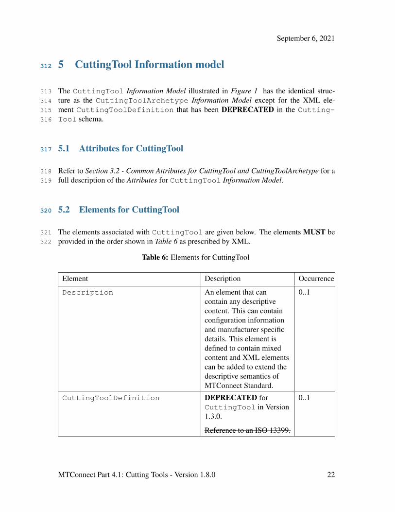
5 CuttingTool Information model312
The CuttingTool Information Model illustrated in Figure 1 has the identical struc-313
ture as the CuttingToolArchetype Information Model except for the XML ele-314
ment CuttingToolDefinition that has been DEPRECATED in the Cutting-315
Tool schema.316
5.1 Attributes for CuttingTool317
Refer to Section 3.2 - Common Attributes for CuttingTool and CuttingToolArchetype for a318
full description of the Attributes for CuttingTool Information Model.319
5.2 Elements for CuttingTool320
The elements associated with CuttingTool are given below. The elements MUST be321
provided in the order shown in Table 6 as prescribed by XML.322
Table 6: Elements for CuttingTool
Element Description Occurrence
Description An element that cancontain any descriptivecontent. This can containconfiguration informationand manufacturer specificdetails. This element isdefined to contain mixedcontent and XML elementscan be added to extend thedescriptive semantics ofMTConnect Standard.
0..1
CuttingToolDefinition DEPRECATED forCuttingTool in Version1.3.0.
Reference to an ISO 13399.
0..1
MTConnect Part 4.1: Cutting Tools - Version 1.8.0 22

September 6, 2021
Continuation of Table 6
Element Description Occurrence
CuttingToolLifeCycle Data regarding the use ofthis tool.
0..1
CuttingToolArchetypeReference The content of this XMLelement is the assetId ofthe Cutting-ToolArchetypedocument. It MAY alsocontain a source attributethat gives the URL of thearchetype data as well.
0..1
5.2.1 CuttingToolLifeCycle Elements for CuttingTool Only323
The following CuttingToolLifeCycle elements are used only in the Cutting-324
Tool Information Model and are not part of the CuttingToolArchetype Informa-325
tion Model. Refer to Section 6 - Common Entity CuttingToolLifeCycle for a complete326
description of the remaining elements for CuttingToolLifeCycle that are common327
in both Information Models. Refer also to the CuttingToolLifeCycle schema illus-328
trated in Figure 14 .329
5.2.1.1 CutterStatus Element for CuttingToolLifeCycle330
Figure 9: CutterStatus Schema
The elements of the CutterStatus element can be a combined set of Status ele-331
ments. The MTConnect Standard allows any set of statuses to be combined, but only332
certain combinations make sense. A CuttingTool SHOULD not be both NEW and333
MTConnect Part 4.1: Cutting Tools - Version 1.8.0 23
September 6, 2021
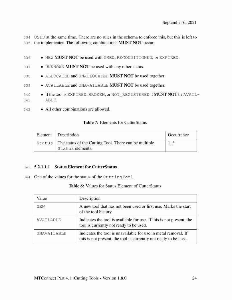
USED at the same time. There are no rules in the schema to enforce this, but this is left to334
the implementer. The following combinations MUST NOT occur:335
• NEW MUST NOT be used with USED, RECONDITIONED, or EXPIRED.336
• UNKNOWN MUST NOT be used with any other status.337
• ALLOCATED and UNALLOCATED MUST NOT be used together.338
• AVAILABLE and UNAVAILABLE MUST NOT be used together.339
• If the tool is EXPIRED, BROKEN, or NOT_REGISTERED it MUST NOT be AVAIL-340
ABLE.341
• All other combinations are allowed.342
Table 7: Elements for CutterStatus
Element Description Occurrence
Status The status of the Cutting Tool. There can be multipleStatus elements.
1..*
5.2.1.1.1 Status Element for CutterStatus343
One of the values for the status of the CuttingTool.344
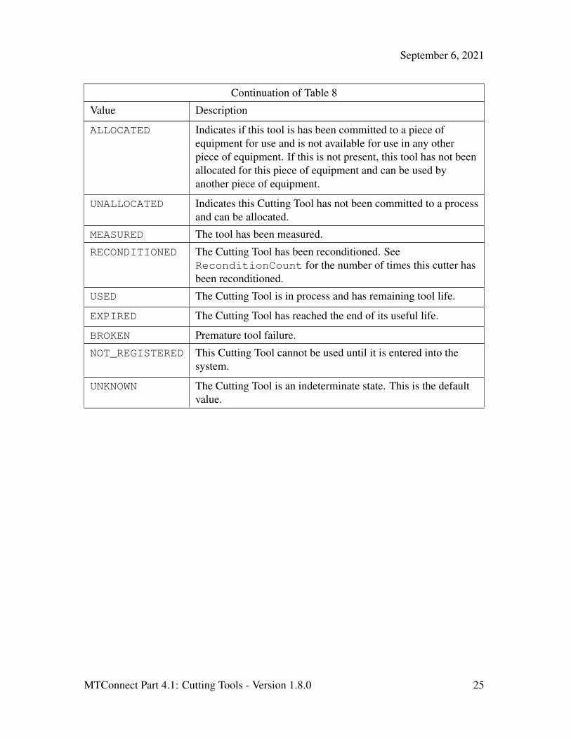
Table 8: Values for Status Element of CutterStatus
Value Description
NEW A new tool that has not been used or first use. Marks the startof the tool history.
AVAILABLE Indicates the tool is available for use. If this is not present, thetool is currently not ready to be used.
UNAVAILABLE Indicates the tool is unavailable for use in metal removal. Ifthis is not present, the tool is currently not ready to be used.
MTConnect Part 4.1: Cutting Tools - Version 1.8.0 24
September 6, 2021
Continuation of Table 8
Value Description
ALLOCATED Indicates if this tool is has been committed to a piece ofequipment for use and is not available for use in any otherpiece of equipment. If this is not present, this tool has not beenallocated for this piece of equipment and can be used byanother piece of equipment.
UNALLOCATED Indicates this Cutting Tool has not been committed to a processand can be allocated.
MEASURED The tool has been measured.
RECONDITIONED The Cutting Tool has been reconditioned. SeeReconditionCount for the number of times this cutter hasbeen reconditioned.
USED The Cutting Tool is in process and has remaining tool life.
EXPIRED The Cutting Tool has reached the end of its useful life.
BROKEN Premature tool failure.
NOT_REGISTERED This Cutting Tool cannot be used until it is entered into thesystem.
UNKNOWN The Cutting Tool is an indeterminate state. This is the defaultvalue.
MTConnect Part 4.1: Cutting Tools - Version 1.8.0 25

September 6, 2021
5.2.1.2 ToolLife Element for CuttingToolLifeCycle345
Figure 10: ToolLife Schema
The value is the current value for the ToolLife. The value MUST be numeric. Tool-346
Life is an option element which can have three types, either minutes for time based, part347
count for parts based, or wear based using a distance measure. One ToolLife element348
can appear for each type, but there cannot be two entries of the same type. Additional349
types can be added in the future.350
MTConnect Part 4.1: Cutting Tools - Version 1.8.0 26
September 6, 2021
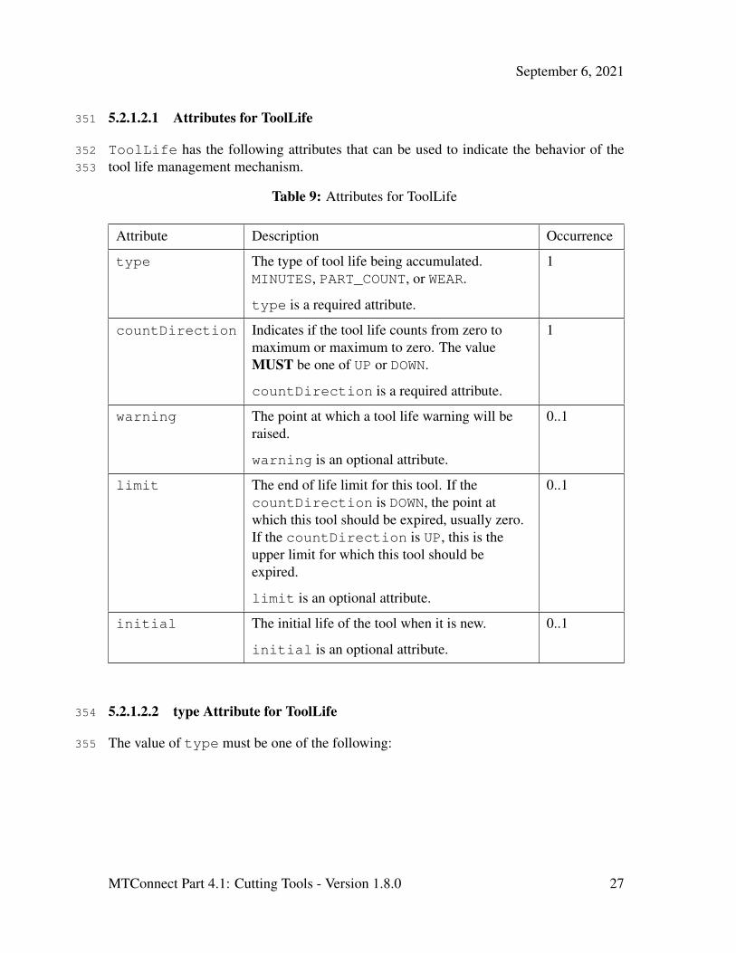
5.2.1.2.1 Attributes for ToolLife351
ToolLife has the following attributes that can be used to indicate the behavior of the352
tool life management mechanism.353
Table 9: Attributes for ToolLife
Attribute Description Occurrence
type The type of tool life being accumulated.MINUTES, PART_COUNT, or WEAR.
type is a required attribute.
1
countDirection Indicates if the tool life counts from zero tomaximum or maximum to zero. The valueMUST be one of UP or DOWN.
countDirection is a required attribute.
1
warning The point at which a tool life warning will beraised.
warning is an optional attribute.
0..1
limit The end of life limit for this tool. If thecountDirection is DOWN, the point atwhich this tool should be expired, usually zero.If the countDirection is UP, this is theupper limit for which this tool should beexpired.
limit is an optional attribute.
0..1
initial The initial life of the tool when it is new.
initial is an optional attribute.
0..1
5.2.1.2.2 type Attribute for ToolLife354
The value of type must be one of the following:355
MTConnect Part 4.1: Cutting Tools - Version 1.8.0 27

September 6, 2021
Table 10: Values for type of ToolLife
Value Description
MINUTES The tool life measured in minutes. All units for minimum,maximum, and nominal MUST be provided in minutes.
PART_COUNT The tool life measured in parts. All units for minimum, maximum,and nominal MUST be provided as the number of parts.
WEAR The tool life measured in tool wear. Wear MUST be provided inmillimeters as an offset to nominal. All units for minimum,maximum, and nominal MUST be given as millimeter offsets aswell. The standard will only consider dimensional wear at this time.
5.2.1.2.3 countDirection Attribute for ToolLife356
The value of countDirection must be one of the following:357
Table 11: Values for countDirection
Value Description
UP The tool life counts up from zero to the maximum.
DOWN The tool life counts down from the maximum to zero.
5.2.1.3 Location Element for CuttingToolLifeCycle358
MTConnect Part 4.1: Cutting Tools - Version 1.8.0 28

September 6, 2021
Figure 11: Location Schema
Location element identifies the specific location where a tool resides in a piece of equip-359
ment tool storage or in a tool crib. This can be any series of numbers and letters as defined360
by the XML type NMTOKEN. When a POT or STATION type is used, the value MUST361
be a numeric value. If a negativeOverlap or the positiveOverlap is provided,362
the tool reserves additional locations on either side, otherwise if they are not given, no363
additional locations are required for this tool. If the pot occupies the first or last location,364
a rollover to the beginning or the end of the index-able values may occur. For example, if365
there are 64 pots and the tool is in pot 64 with a positiveOverlap of 1, the first pot366
MAY be occupied as well.367
5.2.1.3.1 Attributes for Location368
MTConnect Part 4.1: Cutting Tools - Version 1.8.0 29

September 6, 2021
Table 12: Attributes for Location
Attribute Description Occurrence
type The type of location being identified.
type MUST be one of POT, STATION,CRIB, SPINDLE, TRANSFER_POT,RETURN_POT, STAGING_POT,REMOVAL_POT, EXPIRED_POT, orEND_EFFECTOR.
type is a required attribute.
1
positiveOverlap The number of locations at higher indexvalue from this location.
positiveOverlap is a optionalattribute.
0..1
negativeOverlap The number of location at lower indexvalues from this location.
negativeOverlap is an optionalattribute.
0..1
turret The turret associated with a tool.
turret MUST be an XMLNMTOKEN type.
0..1
toolMagazine The tool magazine associated with a tool.
toolMagazine MUST be an XMLNMTOKEN type.
0..1
toolBar The tool bar associated with a tool.
toolBar MUST be an XMLNMTOKEN type.
0..1
toolRack The tool rack associated with a tool.
toolRack MUST be an XMLNMTOKEN type.
0..1
automaticToolChanger The automatic tool changer associatedwith a tool.
automaticToolChanger MUST bean XML NMTOKEN type.
0..1
MTConnect Part 4.1: Cutting Tools - Version 1.8.0 30
September 6, 2021
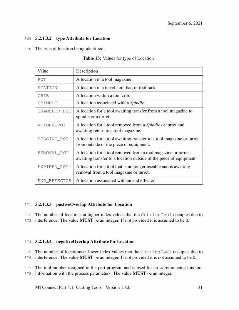
5.2.1.3.2 type Attribute for Location369
The type of location being identified.370
Table 13: Values for type of Location
Value Description
POT A location in a tool magazine.
STATION A location in a turret, tool bar, or tool rack.
CRIB A location within a tool crib.
SPINDLE A location associated with a Spindle.
TRANSFER_POT A location for a tool awaiting transfer from a tool magazine tospindle or a turret.
RETURN_POT A location for a tool removed from a Spindle or turret andawaiting return to a tool magazine.
STAGING_POT A location for a tool awaiting transfer to a tool magazine or turretfrom outside of the piece of equipment.
REMOVAL_POT A location for a tool removed from a tool magazine or turretawaiting transfer to a location outside of the piece of equipment.
EXPIRED_POT A location for a tool that is no longer useable and is awaitingremoval from a tool magazine or turret.
END_EFFECTOR A location associated with an end effector.
5.2.1.3.3 postiveOverlap Attribute for Location371
The number of locations at higher index values that the CuttingTool occupies due to372
interference. The value MUST be an integer. If not provided it is assumed to be 0.373
5.2.1.3.4 negativeOverlap Attribute for Location374
The number of locations at lower index values that the CuttingTool occupies due to375
interference. The value MUST be an integer. If not provided it is not assumed to be 0.376
The tool number assigned in the part program and is used for cross referencing this tool377
information with the process parameters. The value MUST be an integer.378
MTConnect Part 4.1: Cutting Tools - Version 1.8.0 31
September 6, 2021
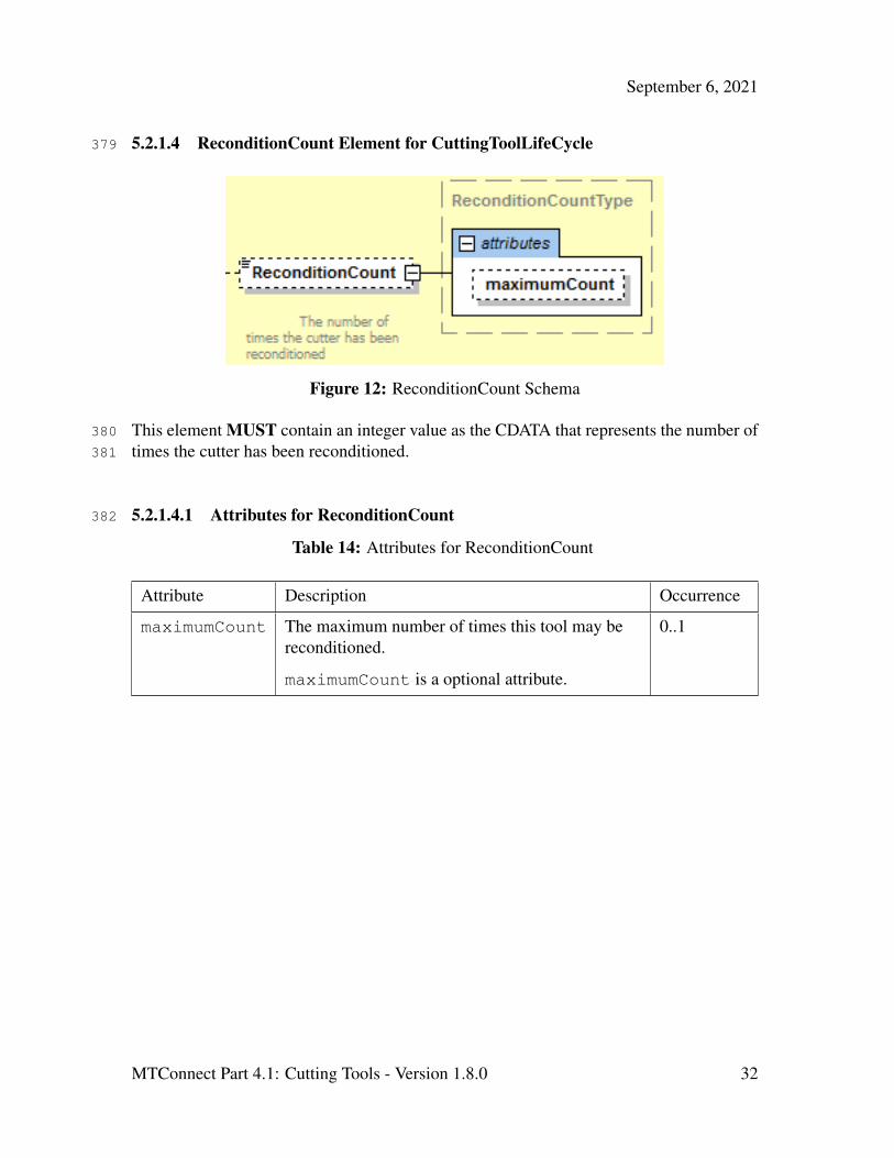
5.2.1.4 ReconditionCount Element for CuttingToolLifeCycle379
Figure 12: ReconditionCount Schema
This element MUST contain an integer value as the CDATA that represents the number of380
times the cutter has been reconditioned.381
5.2.1.4.1 Attributes for ReconditionCount382
Table 14: Attributes for ReconditionCount
Attribute Description Occurrence
maximumCount The maximum number of times this tool may bereconditioned.
maximumCount is a optional attribute.
0..1
MTConnect Part 4.1: Cutting Tools - Version 1.8.0 32
September 6, 2021
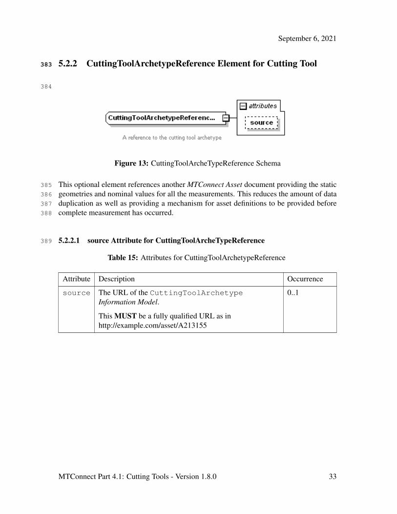
5.2.2 CuttingToolArchetypeReference Element for Cutting Tool383
384
Figure 13: CuttingToolArcheTypeReference Schema
This optional element references another MTConnect Asset document providing the static385
geometries and nominal values for all the measurements. This reduces the amount of data386
duplication as well as providing a mechanism for asset definitions to be provided before387
complete measurement has occurred.388
5.2.2.1 source Attribute for CuttingToolArcheTypeReference389
Table 15: Attributes for CuttingToolArchetypeReference
Attribute Description Occurrence
source The URL of the CuttingToolArchetypeInformation Model.
This MUST be a fully qualified URL as inhttp://example.com/asset/A213155
0..1
MTConnect Part 4.1: Cutting Tools - Version 1.8.0 33
September 6, 2021
6 Common Entity CuttingToolLifeCycle390
6.1 CuttingToolLifeCycle391
The life cycle refers to the data pertaining to the application or the use of the tool. This392
data is provided by various pieces of equipment (i.e. machine tool, presetter) and statis-393
tical process control applications. Life cycle data will not remain static, but will change394
periodically when a tool is used or measured. The life cycle has three conceptual parts;395
CuttingTool and CuttingItem identity, properties, and measurements. A measure-396
ment is defined as a constrained value that is reported in defined units and as a W3C397
floating point format.398
The CuttingToolLifeCycle contains data for the entire tool assembly. The specific399
CuttingItems that are part of the CuttingToolLifeCycle are contained in the400
CuttingItems element. Each Cutting Item has similar properties as the assembly;401
identity, properties, and Measurements.402
The units for all Measurements have been predefined in the MTConnect Standard and403
will be consistent with MTConnect Standard: Part 2.0 - Devices Information Model and404
MTConnect Standard: Part 3.0 - Streams Information Model. This means that all lengths405
and distances will be given in millimeters and all angular measures will be given in de-406
grees. Quantities like ProcessSpindleSpeed will be given in RPM, the same as the407
ROTARY_VELOCITY in MTConnect Standard: Part 3.0 - Streams Information Model.408
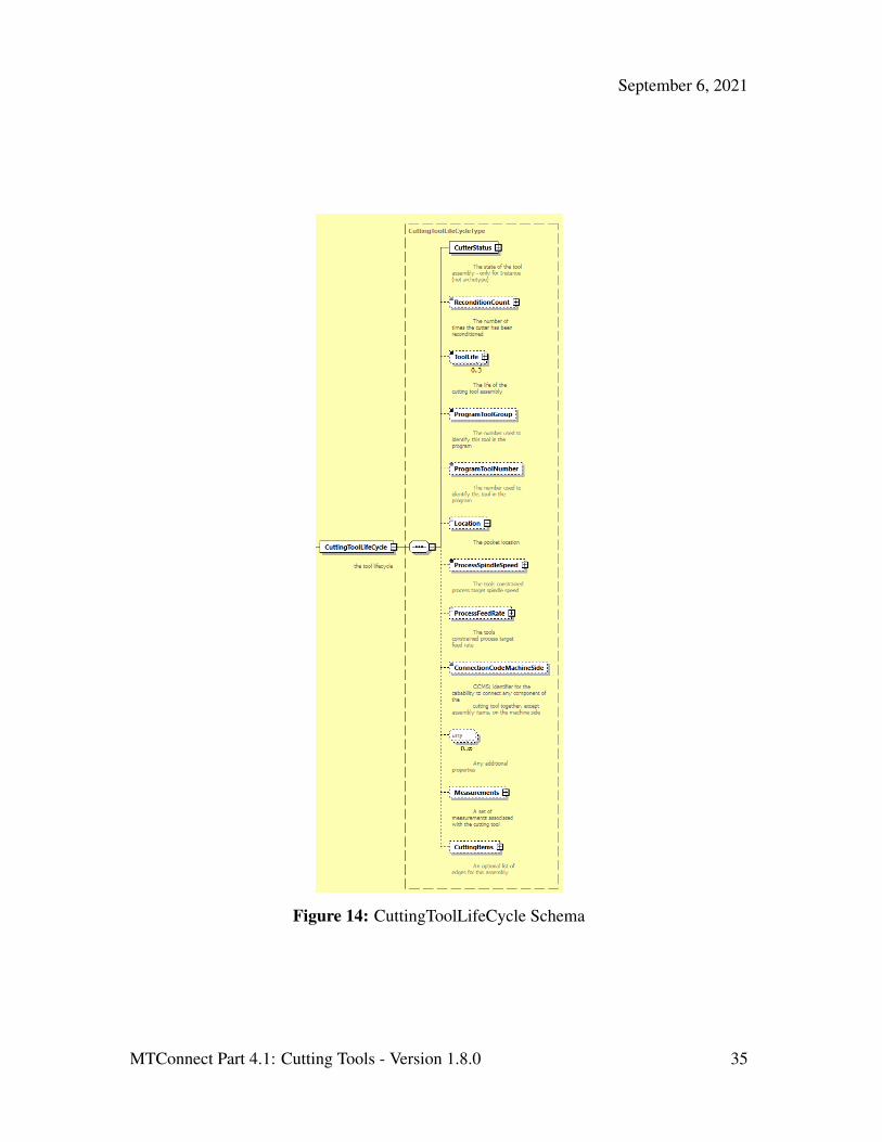
6.1.1 XML Schema Structure for CuttingToolLifeCycle409
The CuttingToolLifeCycle schema shown in Figure 14 is used in both the Cut-410
tingToolArchetype and CuttingTool Information Models. The only difference411
is that the elements CutterStatus, ToolLife, Location, and Recondition-412
Count are used only in the CuttingTool Information Model.413
MTConnect Part 4.1: Cutting Tools - Version 1.8.0 34
September 6, 2021
Figure 14: CuttingToolLifeCycle Schema
MTConnect Part 4.1: Cutting Tools - Version 1.8.0 35
September 6, 2021
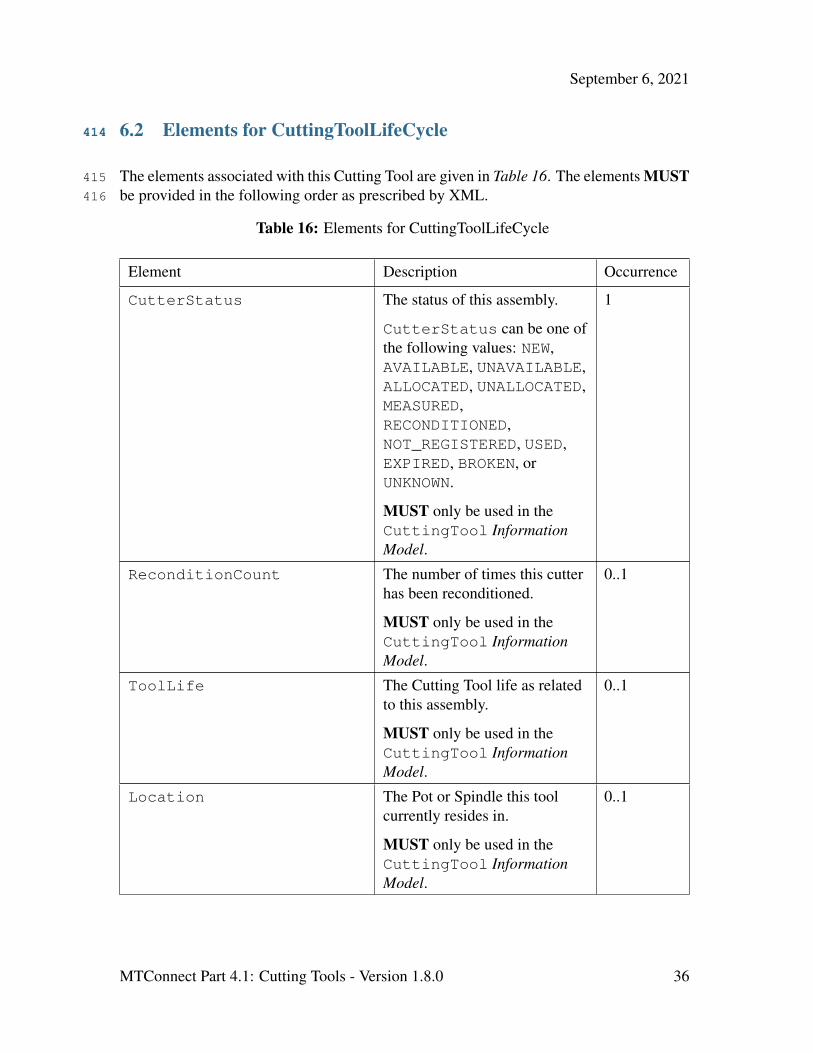
6.2 Elements for CuttingToolLifeCycle414
The elements associated with this Cutting Tool are given in Table 16. The elements MUST415
be provided in the following order as prescribed by XML.416
Table 16: Elements for CuttingToolLifeCycle
Element Description Occurrence
CutterStatus The status of this assembly.
CutterStatus can be one ofthe following values: NEW,AVAILABLE, UNAVAILABLE,ALLOCATED, UNALLOCATED,MEASURED,RECONDITIONED,NOT_REGISTERED, USED,EXPIRED, BROKEN, orUNKNOWN.
MUST only be used in theCuttingTool InformationModel.
1
ReconditionCount The number of times this cutterhas been reconditioned.
MUST only be used in theCuttingTool InformationModel.
0..1
ToolLife The Cutting Tool life as relatedto this assembly.
MUST only be used in theCuttingTool InformationModel.
0..1
Location The Pot or Spindle this toolcurrently resides in.
MUST only be used in theCuttingTool InformationModel.
0..1
MTConnect Part 4.1: Cutting Tools - Version 1.8.0 36

September 6, 2021
Continuation of Table 16
Element Description Occurrence
ProgramToolGroup The tool group this tool isassigned in the part program.
0..1
ProgramToolNumber The number of the tool asreferenced in the part program.
0..1
ProcessSpindleSpeed The constrained process spindlespeed for this tool.
0..1
ProcessFeedRate The constrained process feedrate for this tool in mm/s.
0..1
ConnectionCodeMachineSide Identifier for the capability toconnect any component of theCutting Tool together, exceptAssembly Items, on themachine side. Code: CCMS
0..1
Measurements A collection of measurementsfor the tool assembly.
0..1
CuttingItems An optional set of individualCutting Items.
0..1
xs:any Any additional properties not inthe current document model.MUST be in separate XMLnamespace.
0..n
6.2.1 ProgramToolGroup Element for CuttingToolLifeCycle417
The optional identifier for the group of Cutting Tools when multiple tools can be used418
interchangeably. This is defined as an XML string type and is implementation dependent.419
6.2.2 ProgramToolNumber Element for CuttingToolLifeCycle420
The tool number assigned in the part program and is used for cross referencing this tool421
information with the process parameters. The value MUST be a string.422
MTConnect Part 4.1: Cutting Tools - Version 1.8.0 37

September 6, 2021
6.2.3 ProcessSpindleSpeed Element for CuttingToolLifeCycle423
Figure 15: ProcessSpindleSpeed Schema
The ProcessSpindleSpeed MUST be specified in revolutions/minute (RPM). The424
CDATA MAY contain the nominal process target spindle speed if available. The maximum425
and minimum speeds MAY be provided as attributes. If ProcessSpindleSpeed is426
provided, at least one value of maximum, nominal, or minimum MUST be specified.427
6.2.3.1 Attributes for ProcessSpindleSpeed428
Table 17: Attributes for ProcessSpindleSpeed
Attribute Description Occurrence
maximum The upper bound for the tool’s target spindle speed.
maximum is an optional attribute.
0..1
minimum The lower bound for the tools spindle speed.
minimum is a optional attribute.
0..1
nominal The nominal speed the tool is designed to operate at.
nominal is an optional attribute.
0..1
MTConnect Part 4.1: Cutting Tools - Version 1.8.0 38
September 6, 2021
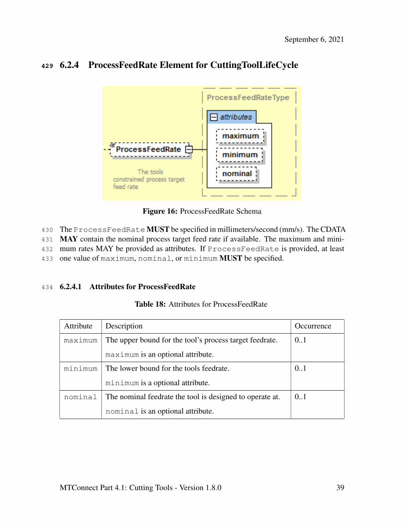
6.2.4 ProcessFeedRate Element for CuttingToolLifeCycle429
Figure 16: ProcessFeedRate Schema
The ProcessFeedRateMUST be specified in millimeters/second (mm/s). The CDATA430
MAY contain the nominal process target feed rate if available. The maximum and mini-431
mum rates MAY be provided as attributes. If ProcessFeedRate is provided, at least432
one value of maximum, nominal, or minimum MUST be specified.433
6.2.4.1 Attributes for ProcessFeedRate434
Table 18: Attributes for ProcessFeedRate
Attribute Description Occurrence
maximum The upper bound for the tool’s process target feedrate.
maximum is an optional attribute.
0..1
minimum The lower bound for the tools feedrate.
minimum is a optional attribute.
0..1
nominal The nominal feedrate the tool is designed to operate at.
nominal is an optional attribute.
0..1
MTConnect Part 4.1: Cutting Tools - Version 1.8.0 39

September 6, 2021
6.2.5 ConnectionCodeMachineSide Element for CuttingToolLifeCy-435
cle436
This is an optional identifier for implementation specific connection component of the437
Cutting Tool on the machine side. Code: CCMS. The CDATA MAY be any valid string438
according to the referenced connection code standards.439
6.2.6 xs:any Element for CuttingToolLifeCycle440
Utilizing XML Schema 1.1, extension points are available where an additional element441
can be added to the document without being part of a substitution group. The new ele-442
ments MUST NOT be part of the MTConnect namespace and MUST NOT be one of the443
predefined elements mentioned above.444
This allows additional properties to be defined for CuttingTool without having to445
change the definition of the definition of the CuttingTool or modify the standard, but446
requires XML Schema Version 1.1.447
6.2.7 Measurements Element for CuttingToolLifeCycle448
The Measurements element is a collection of one or more constrained scalar values449
associated with this Cutting Tool. The XML element MUST be a type extension of the450
base types CommonMeasurement or AssemblyMeasurement. The following sec-451
tion defines the abstract Measurement type used in both CuttingToolLifeCycle452
and CuttingItem. This subsequent sections describe the AssemblyMeasurement453
types followed by the CuttingItemMeasurement types.454
A Measurement is specific to the tool management policy at a particular shop. The tool455
zero reference point or gauge line will be different depending on the particular implemen-456
tation and will be assumed to be consistent within the shop. MTConnect Standard does457
not standardize the manufacturing process or the definition of the zero point.458
MTConnect Part 4.1: Cutting Tools - Version 1.8.0 40

September 6, 2021
6.2.8 Measurement459
Figure 17: Measurement Schema
A Measurement MUST be a scalar floating-point value that MAY be constrained to a460
maximum and minimum value. Since the CuttingToolLifeCycle’s main responsi-461
bility is to track aspects of the tool that change over its use in the shop, MTConnect repre-462
sents the current value of the Measurement MUST be in the CDATA (text between the463
start and end element) as the most current valid value.464
The minimum and maximum MAY be supplied if they are known or relevant to the465
Measurement. A nominal value MAY be provided to show the reference value for466
this Measurement.467
There are three abstract subtypes of Measurement: CommonMeasurement, Assem-468
blyMeasurement, and CuttingItemMeasurement. These abstract types MUST469
NOT appear in an MTConnectAssets document, but are used in the schema as a way470
to separate which measurements MAY appear in the different sections of the document.471
Only subtypes that have extended these types MAY appear in the MTConnectAssets472
XML.473
Measurements in the CuttingToolLifeCycle section MUST refer to the en-474
tire assembly and not to an individual CuttingItem. CuttingItem measurements475
MUST be located in the measurements associated with the individual CuttingItem.476
Measurements MAY provide an optional units attribute to reinforce the given units.477
The units MUST always be given in the predefined MTConnect units. If units are478
MTConnect Part 4.1: Cutting Tools - Version 1.8.0 41
September 6, 2021
provided, they are only for documentation purposes. nativeUnits MAY optionally be479
provided to indicate the original units provided for the measurements.480
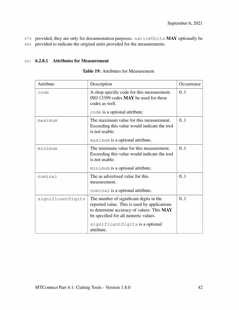
6.2.8.1 Attributes for Measurement481
Table 19: Attributes for Measurement
Attribute Description Occurrence
code A shop specific code for this measurement.ISO 13399 codes MAY be used for thesecodes as well.
code is a optional attribute.
0..1
maximum The maximum value for this measurement.Exceeding this value would indicate the toolis not usable.
maximum is a optional attribute.
0..1
minimum The minimum value for this measurement.Exceeding this value would indicate the toolis not usable.
minimum is a optional attribute.
0..1
nominal The as advertised value for thismeasurement.
nominal is a optional attribute.
0..1
significantDigits The number of significant digits in thereported value. This is used by applicationsto determine accuracy of values. This MAYbe specified for all numeric values.
significantDigits is a optionalattribute.
0..1
MTConnect Part 4.1: Cutting Tools - Version 1.8.0 42

September 6, 2021
Continuation of Table 19
Attribute Description Occurrence
units The units for the measurements. MTConnectStandard defines all the units for eachmeasurement, so this is mainly fordocumentation sake. See MTConnectMTConnect Standard: Part 2.0 - DevicesInformation Model 7.2.2.5 for the full list ofunits.
units is a optional attribute.
0..1
nativeUnits The units the measurement was originallyrecorded in. This is only necessary if theydiffer from units. See MTConnect Standard:Part 2.0 - Devices Information ModelSection 7.2.2.6 for the full list of units.
nativeUnits is a optional attribute.
0..1
6.2.8.2 Measurement Subtypes for CuttingToolLifeCycle482
These Measurements for CuttingTool are specific to the entire assembly and MUST483
NOT be used for the Measurement pertaining to a CuttingItem. Figure 18 and Fig-484
ure 19 will be used to reference the assembly specific Measurements.485
The Code in Table 20 will refer to the acronyms in the diagrams. We will be referring to486
many diagrams to disambiguate all measurements of the CuttingTool and Cuttin-487
gItem.488
Figure 18: Cutting Tool Measurement Diagram 1
MTConnect Part 4.1: Cutting Tools - Version 1.8.0 43

September 6, 2021
Figure 19: Cutting Tool Measurement Diagram 2
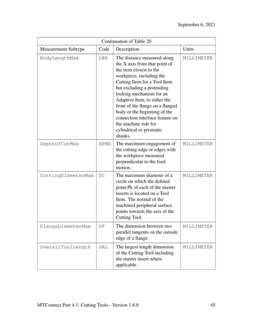
Table 20: Measurement Subtypes for CuttingTool
Measurement Subtype Code Description Units
BodyDiameterMax BDX The largest diameter of thebody of a Tool Item.
MILLIMETER
MTConnect Part 4.1: Cutting Tools - Version 1.8.0 44
September 6, 2021
Continuation of Table 20
Measurement Subtype Code Description Units
BodyLengthMax LBX The distance measured alongthe X axis from that point ofthe item closest to theworkpiece, including theCutting Item for a Tool Itembut excluding a protrudinglocking mechanism for anAdaptive Item, to either thefront of the flange on a flangedbody or the beginning of theconnection interface feature onthe machine side forcylindrical or prismaticshanks.
MILLIMETER
DepthOfCutMax APMX The maximum engagement ofthe cutting edge or edges withthe workpiece measuredperpendicular to the feedmotion.
MILLIMETER
CuttingDiameterMax DC The maximum diameter of acircle on which the definedpoint Pk of each of the masterinserts is located on a ToolItem. The normal of themachined peripheral surfacepoints towards the axis of theCutting Tool.
MILLIMETER
FlangeDiameterMax DF The dimension between twoparallel tangents on the outsideedge of a flange.
MILLIMETER
OverallToolLength OAL The largest length dimensionof the Cutting Tool includingthe master insert whereapplicable.
MILLIMETER
MTConnect Part 4.1: Cutting Tools - Version 1.8.0 45
September 6, 2021
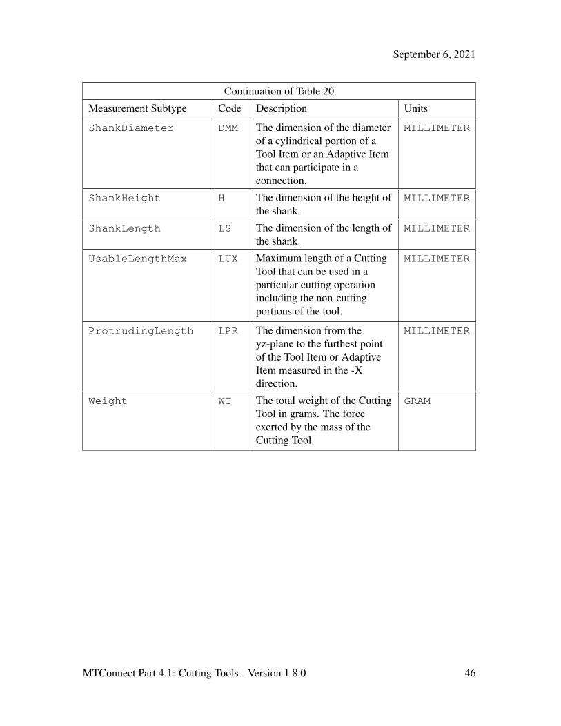
Continuation of Table 20
Measurement Subtype Code Description Units
ShankDiameter DMM The dimension of the diameterof a cylindrical portion of aTool Item or an Adaptive Itemthat can participate in aconnection.
MILLIMETER
ShankHeight H The dimension of the height ofthe shank.
MILLIMETER
ShankLength LS The dimension of the length ofthe shank.
MILLIMETER
UsableLengthMax LUX Maximum length of a CuttingTool that can be used in aparticular cutting operationincluding the non-cuttingportions of the tool.
MILLIMETER
ProtrudingLength LPR The dimension from theyz-plane to the furthest pointof the Tool Item or AdaptiveItem measured in the -Xdirection.
MILLIMETER
Weight WT The total weight of the CuttingTool in grams. The forceexerted by the mass of theCutting Tool.
GRAM
MTConnect Part 4.1: Cutting Tools - Version 1.8.0 46

September 6, 2021
Continuation of Table 20
Measurement Subtype Code Description Units
FunctionalLength LF The distance from the gaugeplane or from the end of theshank to the furthest point onthe tool, if a gauge plane doesnot exist, to the cuttingreference point determined bythe main function of the tool.The CuttingToolfunctional length will be thelength of the entire tool, not asingle Cutting Item. EachCuttingItem can have anindependentFunctionalLengthrepresented in itsmeasurements.
MILLIMETER
6.2.9 CuttingItems Element for CuttingToolLifeCycle489
Figure 20: CuttingItems Schema
An optional collection of CuttingItems that SHOULD be provided for each indepen-490
dent edge or insert. If the CuttingItems are not present; it indicates there is no specific491
information with respect to each of the CuttingItems. This does not imply there are no492
CuttingItems – there MUST be at least one CuttingItem – but there is no specific493
information.494
MTConnect Part 4.1: Cutting Tools - Version 1.8.0 47
September 6, 2021
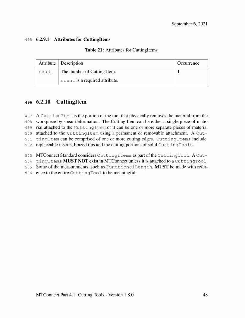
6.2.9.1 Attributes for CuttingItems495
Table 21: Attributes for CuttingItems
Attribute Description Occurrence
count The number of Cutting Item.
count is a required attribute.
1
6.2.10 CuttingItem496
A CuttingItem is the portion of the tool that physically removes the material from the497
workpiece by shear deformation. The Cutting Item can be either a single piece of mate-498
rial attached to the CuttingItem or it can be one or more separate pieces of material499
attached to the CuttingItem using a permanent or removable attachment. A Cut-500
tingItem can be comprised of one or more cutting edges. CuttingItems include:501
replaceable inserts, brazed tips and the cutting portions of solid CuttingTools.502
MTConnect Standard considers CuttingItems as part of the CuttingTool. A Cut-503
tingItems MUST NOT exist in MTConnect unless it is attached to a CuttingTool.504
Some of the measurements, such as FunctionalLength, MUST be made with refer-505
ence to the entire CuttingTool to be meaningful.506
MTConnect Part 4.1: Cutting Tools - Version 1.8.0 48

September 6, 2021
Figure 21: CuttingItem Schema
MTConnect Part 4.1: Cutting Tools - Version 1.8.0 49
September 6, 2021
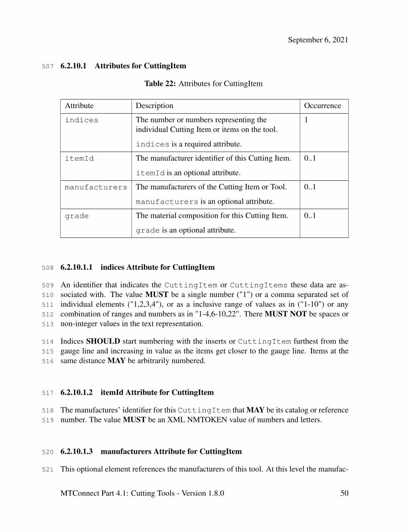
6.2.10.1 Attributes for CuttingItem507
Table 22: Attributes for CuttingItem
Attribute Description Occurrence
indices The number or numbers representing theindividual Cutting Item or items on the tool.
indices is a required attribute.
1
itemId The manufacturer identifier of this Cutting Item.
itemId is an optional attribute.
0..1
manufacturers The manufacturers of the Cutting Item or Tool.
manufacturers is an optional attribute.
0..1
grade The material composition for this Cutting Item.
grade is an optional attribute.
0..1
6.2.10.1.1 indices Attribute for CuttingItem508
An identifier that indicates the CuttingItem or CuttingItems these data are as-509
sociated with. The value MUST be a single number ("1") or a comma separated set of510
individual elements ("1,2,3,4"), or as a inclusive range of values as in ("1-10") or any511
combination of ranges and numbers as in "1-4,6-10,22". There MUST NOT be spaces or512
non-integer values in the text representation.513
Indices SHOULD start numbering with the inserts or CuttingItem furthest from the514
gauge line and increasing in value as the items get closer to the gauge line. Items at the515
same distance MAY be arbitrarily numbered.516
6.2.10.1.2 itemId Attribute for CuttingItem517
The manufactures’ identifier for this CuttingItem that MAY be its catalog or reference518
number. The value MUST be an XML NMTOKEN value of numbers and letters.519
6.2.10.1.3 manufacturers Attribute for CuttingItem520
This optional element references the manufacturers of this tool. At this level the manufac-521
MTConnect Part 4.1: Cutting Tools - Version 1.8.0 50
September 6, 2021
turers will reference the CuttingItem specifically. The representation will be a comma522
(,) delimited list of manufacturer names. This can be any series of numbers and letters as523
defined by the XML type string.524
6.2.10.1.4 grade Attribute for CuttingItem525
This provides an implementation specific designation for the material composition of this526
CuttingItem.527
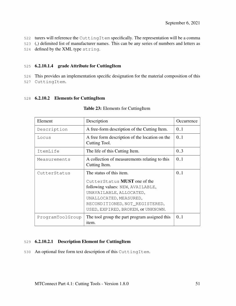
6.2.10.2 Elements for CuttingItem528
Table 23: Elements for CuttingItem
Element Description Occurrence
Description A free-form description of the Cutting Item. 0..1
Locus A free form description of the location on theCutting Tool.
0..1
ItemLife The life of this Cutting Item. 0..3
Measurements A collection of measurements relating to thisCutting Item.
0..1
CutterStatus The status of this item.
CutterStatus MUST one of thefollowing values: NEW, AVAILABLE,UNAVAILABLE, ALLOCATED,UNALLOCATED, MEASURED,RECONDITIONED, NOT_REGISTERED,USED, EXPIRED, BROKEN, or UNKNOWN.
0..1
ProgramToolGroup The tool group the part program assigned thisitem.
0..1
6.2.10.2.1 Description Element for CuttingItem529
An optional free form text description of this CuttingItem.530
MTConnect Part 4.1: Cutting Tools - Version 1.8.0 51

September 6, 2021
6.2.10.2.2 Locus Element for CuttingItem531
Locus represents the location of the CuttingItem with respect to the Cutting Tool.532
For clarity, the words FLUTE, INSERT, and CARTRIDGE SHOULD be used to assist in533
noting the location of a CuttingItem. The Locus MAY be any free form text, but534
SHOULD adhere to the following rules:535
• The location numbering SHOULD start at the furthest CuttingItem (#1) and536
work it’s way back to the Cutting Item closest to the gauge line.537
• Flutes SHOULD be identified as such using the word FLUTE:. For example: FLUTE:538
1, INSERT: 2 - would indicate the first flute and the second furthest insert from the539
end of the tool on that flute.540
• Other designations such as CARTRIDGE MAY be included, but should be identified541
using upper case and followed by a colon (:).542
MTConnect Part 4.1: Cutting Tools - Version 1.8.0 52

September 6, 2021
6.2.10.2.3 ItemLife Element for CuttingItem543
Figure 22: ItemLife Schema
The value is the current value for the ItemLife. The value MUST be numeric. Item-544
Life is an option element which can have three types, either minutes for time based, part545
count for parts based, or wear based using a distance measure. One ItemLife can ap-546
pear for each type, but there cannot be two entries of the same type. Additional types can547
be added in the future.548
MTConnect Part 4.1: Cutting Tools - Version 1.8.0 53

September 6, 2021
6.2.10.2.4 Attributes for ItemLife549
These is an optional attribute that can be used to further classify the operation type.550
Table 24: Attributes for ItemLife
Attribute Description Occurrence
type The type of tool life being accumulated.
Valid Data Values:
MINUTES, PART_COUNT, or WEAR.
type is a required attribute.
1
countDirection Indicates if the tool life counts from zero tomaximum or maximum to zero. The valueMUST be one of UP or DOWN.
countDirection is a required attribute.
1
warning The point at which a tool life warning will beraised.
warning is an optional attribute.
0..1
limit The end of life limit for this tool.
If the countDirection is DOWN, the point atwhich this tool should be expired, usually zero.If the countDirection is UP, this is theupper limit for which this tool should beexpired.
limit is an optional attribute.
0..1
initial The initial life of the tool when it is new.
initial is an optional attribute.
0..1
6.2.10.2.5 type Attribute for ItemLife551
The value of type must be one of the following:552
MTConnect Part 4.1: Cutting Tools - Version 1.8.0 54

September 6, 2021
Table 25: Values for type of ItemLife
Value Description
MINUTES The tool life measured in minutes. All units for minimum,maximum, and nominal MUST be provided in minutes.
PART_COUNT The tool life measured in parts. All units for minimum, maximum,and nominal MUST be provided as the number of parts.
WEAR The tool life measured in tool wear. Wear MUST be provided inmillimeters as an offset to nominal. All units for minimum,maximum, and nominal MUST be given as millimeter offsets aswell.
6.2.10.2.6 countDirection Attribute for ItemLife553
The value of type must be one of the following:554
Table 26: Values for countDirection
Value Description
UP The tool life counts up from zero to the maximum.
DOWN The tool life counts down from the maximum to zero.
6.2.10.3 Measurement Subtypes for CuttingItem555
These Measurements for CuttingItem are specific to an individual CuttingItem556
and MUST NOT be used for the Measurements pertaining to an assembly. The Fig-557
ure 23 , Figure 24 , Figure 25 and Figure 26 will be used to for reference for the Cut-558
tingItem specific Measurements .559
The Code in Table 27 will refer to the acronym in the diagram. We will be referring to560
many diagrams to disambiguate all Measurements of the CuttingTools and Cut-561
tingItems. We will present a few here; please refer to Appendix B for additional562
reference material.563
MTConnect Part 4.1: Cutting Tools - Version 1.8.0 55

September 6, 2021
Figure 23: Cutting Tool
Figure 24: Cutting Item
MTConnect Part 4.1: Cutting Tools - Version 1.8.0 56
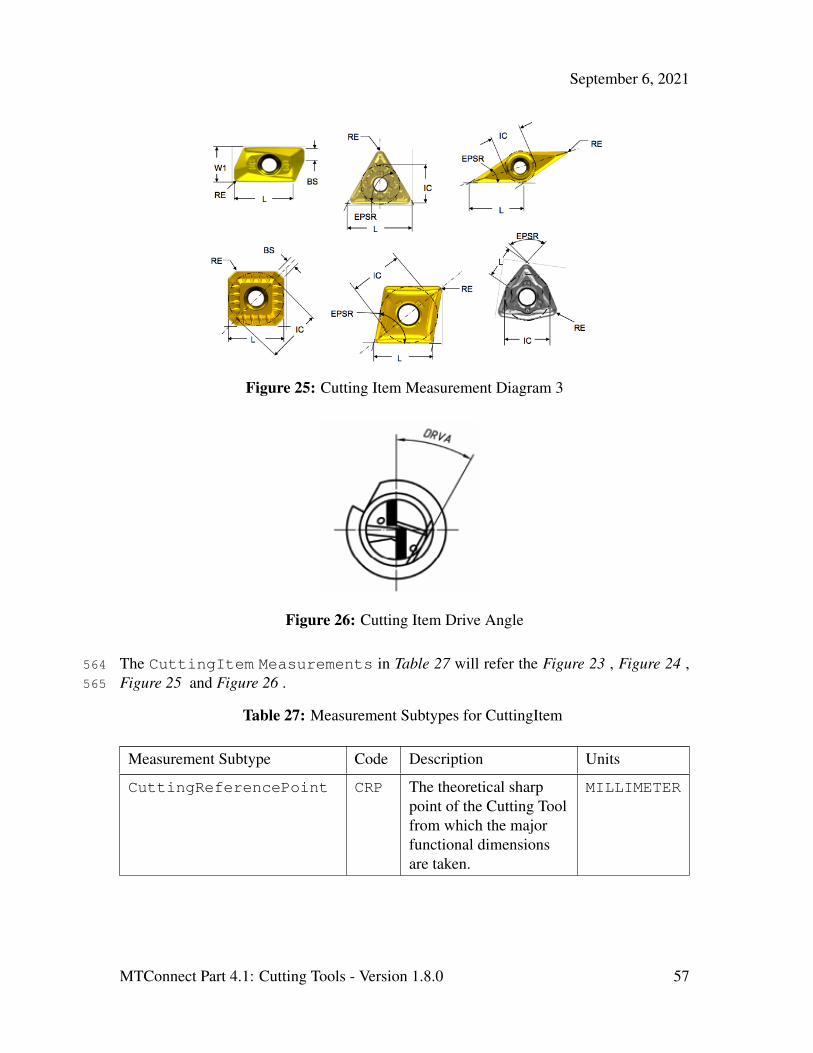
September 6, 2021
Figure 25: Cutting Item Measurement Diagram 3
Figure 26: Cutting Item Drive Angle
The CuttingItem Measurements in Table 27 will refer the Figure 23 , Figure 24 ,564
Figure 25 and Figure 26 .565
Table 27: Measurement Subtypes for CuttingItem
Measurement Subtype Code Description Units
CuttingReferencePoint CRP The theoretical sharppoint of the Cutting Toolfrom which the majorfunctional dimensionsare taken.
MILLIMETER
MTConnect Part 4.1: Cutting Tools - Version 1.8.0 57
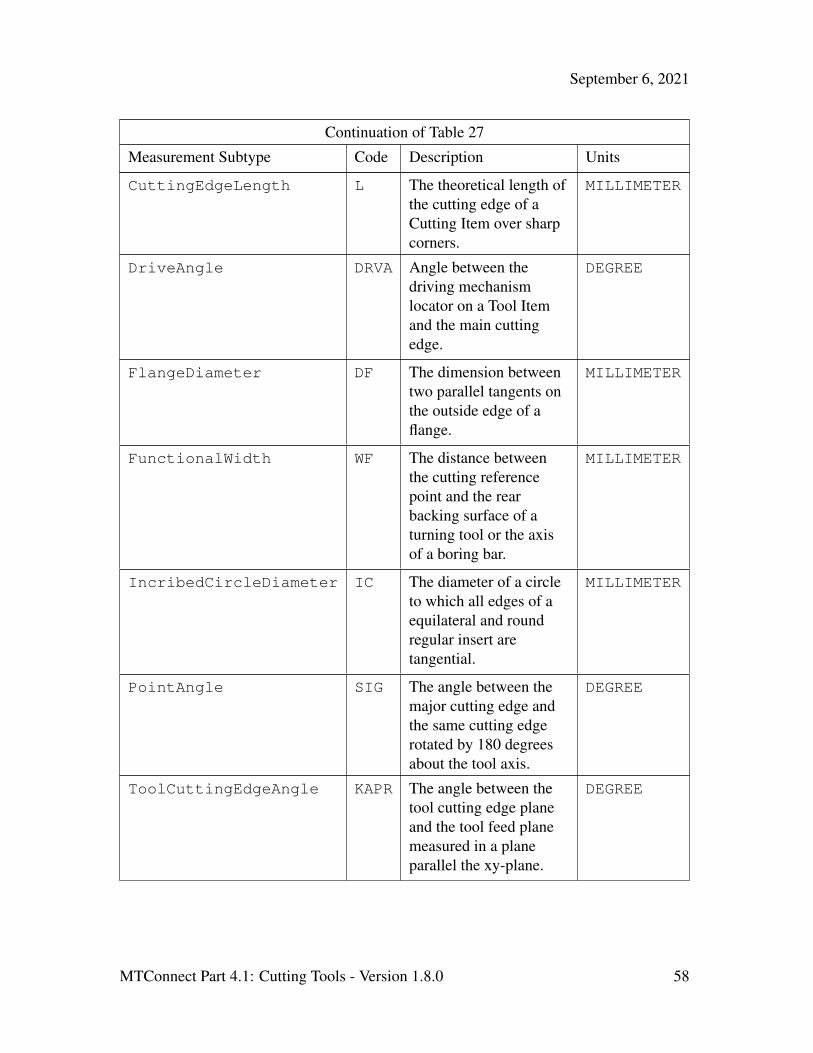
September 6, 2021
Continuation of Table 27
Measurement Subtype Code Description Units
CuttingEdgeLength L The theoretical length ofthe cutting edge of aCutting Item over sharpcorners.
MILLIMETER
DriveAngle DRVA Angle between thedriving mechanismlocator on a Tool Itemand the main cuttingedge.
DEGREE
FlangeDiameter DF The dimension betweentwo parallel tangents onthe outside edge of aflange.
MILLIMETER
FunctionalWidth WF The distance betweenthe cutting referencepoint and the rearbacking surface of aturning tool or the axisof a boring bar.
MILLIMETER
IncribedCircleDiameter IC The diameter of a circleto which all edges of aequilateral and roundregular insert aretangential.
MILLIMETER
PointAngle SIG The angle between themajor cutting edge andthe same cutting edgerotated by 180 degreesabout the tool axis.
DEGREE
ToolCuttingEdgeAngle KAPR The angle between thetool cutting edge planeand the tool feed planemeasured in a planeparallel the xy-plane.
DEGREE
MTConnect Part 4.1: Cutting Tools - Version 1.8.0 58

September 6, 2021
Continuation of Table 27
Measurement Subtype Code Description Units
ToolLeadAngle PSIR The angle between thetool cutting edge planeand a planeperpendicular to the toolfeed plane measured in aplane parallel thexy-plane.
DEGREE
ToolOrientation N/A The angle of the toolwith respect to theworkpiece for a givenprocess. The value isapplication specific.
DEGREE
WiperEdgeLength BS The measure of thelength of a wiper edge ofa Cutting Item.
MILLIMETER
StepDiameterLength SDLx The length of a portionof a stepped tool that isrelated to acorresponding cuttingdiameter measured fromthe cutting referencepoint of that cuttingdiameter to the point onthe next cutting edge atwhich the diameter startsto change.
MILLIMETER
StepIncludedAngle STAx The angle between amajor edge on a step of astepped tool and thesame cutting edgerotated 180 degreesabout its tool axis.
DEGREE
MTConnect Part 4.1: Cutting Tools - Version 1.8.0 59

September 6, 2021
Continuation of Table 27
Measurement Subtype Code Description Units
CuttingDiameter DCx The diameter of a circleon which the definedpoint Pk located on thisCutting Tool. Thenormal of the machinedperipheral surface pointstowards the axis of theCutting Tool.
MILLIMETER
CuttingHeight HF The distance from thebasal plane of the ToolItem to the cutting point.
MILLIMETER
CornerRadius RE The nominal radius of arounded cornermeasured in the XY-plane.
MILLIMETER
Weight WT The total weight of theCutting Tool in grams.The force exerted by themass of the Cutting Tool.
GRAM
FunctionalLength LFx The distance from thegauge plane or from theend of the shank of theCutting Tool, if a gaugeplane does not exist, tothe cutting referencepoint determined by themain function of thetool. This measurementwill be with reference tothe Cutting Tool andMUST NOT existwithout a Cutting Tool.
MILLIMETER
ChamferFlatLength BCH The flat length of achamfer.
MILLIMETER
ChamferWidth CHW The width of thechamfer.
MILLIMETER
MTConnect Part 4.1: Cutting Tools - Version 1.8.0 60

September 6, 2021
Continuation of Table 27
Measurement Subtype Code Description Units
InsertWidth W1 W1 is used for the insertwidth when an inscribedcircle diameter is notpractical.
MILLIMETER
MTConnect Part 4.1: Cutting Tools - Version 1.8.0 61

September 6, 2021
Appendices566
A Bibliography567
Engineering Industries Association. EIA Standard - EIA-274-D, Interchangeable Variable,568
Block Data Format for Positioning, Contouring, and Contouring/Positioning Numerically569
Controlled Machines. Washington, D.C. 1979.570
ISO TC 184/SC4/WG3 N1089. ISO/DIS 10303-238: Industrial automation systems and571
integration Product data representation and exchange Part 238: Application Protocols: Ap-572
plication interpreted model for computerized numerical controllers. Geneva, Switzerland,573
2004.574
International Organization for Standardization. ISO 14649: Industrial automation sys-575
tems and integration – Physical device control – Data model for computerized numerical576
controllers – Part 10: General process data. Geneva, Switzerland, 2004.577
International Organization for Standardization. ISO 14649: Industrial automation sys-578
tems and integration – Physical device control – Data model for computerized numerical579
controllers – Part 11: Process data for milling. Geneva, Switzerland, 2000.580
International Organization for Standardization. ISO 6983/1 – Numerical Control of ma-581
chines – Program format and definition of address words – Part 1: Data format for posi-582
tioning, line and contouring control systems. Geneva, Switzerland, 1982.583
Electronic Industries Association. ANSI/EIA-494-B-1992, 32 Bit Binary CL (BCL) and584
7 Bit ASCII CL (ACL) Exchange Input Format for Numerically Controlled Machines.585
Washington, D.C. 1992.586
National Aerospace Standard. Uniform Cutting Tests - NAS Series: Metal Cutting Equip-587
ment Specifications. Washington, D.C. 1969.588
International Organization for Standardization. ISO 10303-11: 1994, Industrial automa-589
tion systems and integration Product data representation and exchange Part 11: Descrip-590
tion methods: The EXPRESS language reference manual. Geneva, Switzerland, 1994.591
International Organization for Standardization. ISO 10303-21: 1996, Industrial automa-592
tion systems and integration – Product data representation and exchange – Part 21: Imple-593
mentation methods: Clear text encoding of the exchange structure. Geneva, Switzerland,594
1996.595
H.L. Horton, F.D. Jones, and E. Oberg. Machinery’s Handbook. Industrial Press, Inc.596
MTConnect Part 4.1: Cutting Tools - Version 1.8.0 62

September 6, 2021
New York, 1984.597
International Organization for Standardization. ISO 841-2001: Industrial automation sys-598
tems and integration - Numerical control of machines - Coordinate systems and motion599
nomenclature. Geneva, Switzerland, 2001.600
ASME B5.59-2 Version 9c: Data Specification for Properties of Machine Tools for Milling601
and Turning. 2005.602
ASME/ANSI B5.54: Methods for Performance Evaluation of Computer Numerically Con-603
trolled Machining Centers. 2005.604
OPC Foundation. OPC Unified Architecture Specification, Part 1: Concepts Version 1.00.605
July 28, 2006.606
International Organization for Standardization. ISO 13399: Cutting tool data representa-607
tion and exchange. Geneva, Switzerland, 2000.608
MTConnect Part 4.1: Cutting Tools - Version 1.8.0 63
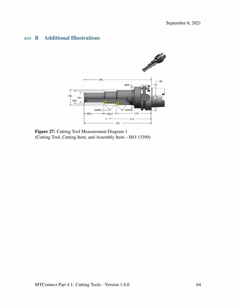
September 6, 2021
B Additional Illustrations609
Figure 27: Cutting Tool Measurement Diagram 1(Cutting Tool, Cutting Item, and Assembly Item – ISO 13399)
MTConnect Part 4.1: Cutting Tools - Version 1.8.0 64
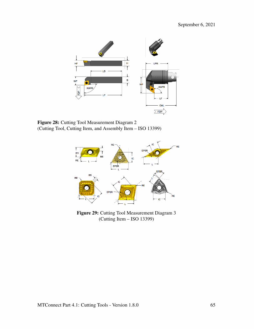
September 6, 2021
Figure 28: Cutting Tool Measurement Diagram 2(Cutting Tool, Cutting Item, and Assembly Item – ISO 13399)
Figure 29: Cutting Tool Measurement Diagram 3(Cutting Item – ISO 13399)
MTConnect Part 4.1: Cutting Tools - Version 1.8.0 65

September 6, 2021
Figure 30: Cutting Tool Measurement Diagram 4(Cutting Item – ISO 13399)
Figure 31: Cutting Tool Measurement Diagram 5(Cutting Item – ISO 13399)
MTConnect Part 4.1: Cutting Tools - Version 1.8.0 66

September 6, 2021
Figure 32: Cutting Tool Measurement Diagram 6(Cutting Item – ISO 13399)
MTConnect Part 4.1: Cutting Tools - Version 1.8.0 67

September 6, 2021
C Cutting Tool Example610
C.1 Shell Mill611
Figure 33: Shell Mill Side View
Figure 34: Indexable Insert Measurements
Example 1: Example for Indexable Insert Measurements1 <?xml version="1.0" encoding="UTF-8"?>6122 <MTConnectAssets6133 xmlns:m="urn:mtconnect.org:MTConnectAssets:1.2"6144 xmlns="urn:mtconnect.org:MTConnectAssets:1.2"6155 xmlns:xsi="http://www.w3.org/2001/XMLSchema-instance"6166 xsi:schemaLocation="urn:mtconnect.org:MTConnectAssets:1.26177 http://mtconnect.org/schemas/MTConnectAssets\_1.2.xsd">6188 <Header creationTime="2011-05-11T13:55:22"6199 assetBufferSize="1024" sender="localhost"620
MTConnect Part 4.1: Cutting Tools - Version 1.8.0 68

September 6, 2021
10 assetCount="2" version="1.2" instanceId="1234"/>62111 <Assets>62212 <CuttingTool serialNumber="1" toolId="KSSP300R4SD43L240"62313 timestamp="2011-05-11T13:55:22" assetId="KSSP300R4SD43L240.1"62414 manufacturers="KMT,Parlec">62515 <CuttingToolLifeCycle>62616 <CutterStatus><Status>NEW</Status></CutterStatus>62717 <ProcessSpindleSpeed maximum="13300"62818 nominal="605">10000</ProcessSpindleSpeed>62919 <ProcessFeedRate63020 nominal="9.22">9.22</ProcessSpindleSpeed>63121 <ConnectionCodeMachineSide>CV5063222 </ConnectionCodeMachineSide>63323 <Measurements>63424 <BodyDiameterMax code="BDX">73.2563525 </BodyDiameterMax>63626 <OverallToolLength nominal="222.25"63727 minimum="221.996" maximum="222.504"63828 code="OAL">222.25</OverallToolLength>63929 <UsableLengthMax code="LUX" nominal="82.55">82.5564030 </UsableLengthMax>64131 <CuttingDiameterMax code="DC" nominal="76.2"64232 maximum="76.213" minimum="76.187">76.264333 </CuttingDiameterMax>64434 <BodyLengthMax code="LF" nominal="120.65"64535 maximum="120.904" minimum="120.404">120.6564636 </BodyLengthMax>64737 <DepthOfCutMax code="APMX"64838 nominal="60.96">60.95</DepthOfCutMax>64939 <FlangeDiameterMax code="DF"65040 nominal="98.425">98.425</FlangeDiameterMax>65141 </Measurements>65242 <CuttingItems count="24">65343 <CuttingItem indices="1-24" itemId="SDET43PDER8GB"65444 manufacturers="KMT" grade="KC725M">65545 <Measurements>65646 <CuttingEdgeLength code="L" nominal="12.7"65747 minimum="12.675" maximum="12.725">12.765848 </CuttingEdgeLength>65949 <WiperEdgeLength code="BS" nominal=66050 "2.56">2.56</WiperEdgeLength>66151 <IncribedCircleDiameter code="IC"66252 nominal="12.7">12.766353 </IncribedCircleDiameter>66454 <CornerRadius code="RE" nominal="0.8">66555 0.8</CornerRadius>66656 </Measurements>66757 </CuttingItem>66858 </CuttingItems>66959 </CuttingToolLifeCycle>67060 </CuttingTool>671
MTConnect Part 4.1: Cutting Tools - Version 1.8.0 69

September 6, 2021
61 </Assets>67262 </MTConnectAssets>673
MTConnect Part 4.1: Cutting Tools - Version 1.8.0 70
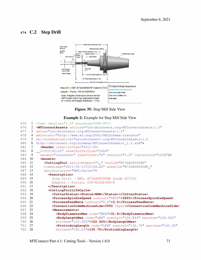
September 6, 2021
C.2 Step Drill674
Figure 35: Step Mill Side View
Example 2: Example for Step Mill Side View1 <?xml version="1.0" encoding="UTF-8"?>6752 <MTConnectAssets xmlns:m="urn:mtconnect.org:MTConnectAssets:1.2"6763 xmlns="urn:mtconnect.org:MTConnectAssets:1.2"6774 xmlns:xsi="http://www.w3.org/2001/XMLSchema-instance"6785 xsi:schemaLocation="urn:mtconnect.org:MTConnectAssets:1.26796 http://mtconnect.org/schemas/MTConnectAssets\_1.2.xsd">6807 <Header creationTime="2011-05-6818 11T13:55:22" assetBufferSize="1024"6829 sender="localhost" assetCount="2" version="1.2" instanceId="1234"/>683
10 <Assets>68411 <CuttingTool serialNumber="1 " toolId="B732A08500HP"68512 timestamp="2011-05-11T13:55:22" assetId="B732A08500HP "68613 manufacturers="KMT,Parlec">68714 <Description>68815 Step Drill - KMT, B732A08500HP Grade KC731568916 Adapter - Parlec, C50-M12SF300-669017 </Description>69118 <CuttingToolLifeCycle>69219 <CutterStatus><Status>NEW</Status></CutterStatus>69320 <ProcessSpindleSpeed nominal="5893">5893</ProcessSpindleSpeed>69421 <ProcessFeedRate nominal="2.5">2.5</ProcessFeedRate>69522 <ConnectionCodeMachineSide>CV50 Taper</ConnectionCodeMachineSide>69623 <Measurements>69724 <BodyDiameterMax code="BDX">31.8</BodyDiameterMax>69825 <BodyLengthMax code="LBX" nominal="120.825" maximum="126.325"69926 minimum="115.325">120.825</BodyLengthMax>70027 <ProtrudingLength code="LPR" nominal="155.75" maximum="161.25"70128 minimum="150.26">155.75</ProtrudingLength>702
MTConnect Part 4.1: Cutting Tools - Version 1.8.0 71
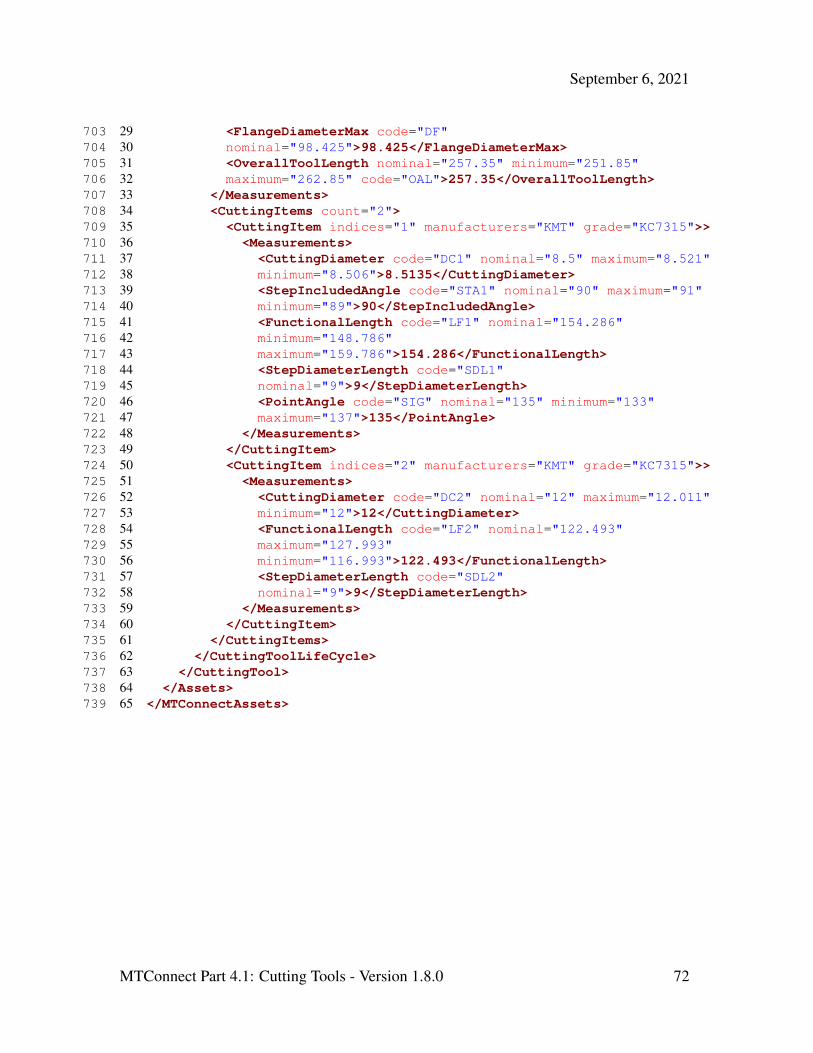
September 6, 2021
29 <FlangeDiameterMax code="DF"70330 nominal="98.425">98.425</FlangeDiameterMax>70431 <OverallToolLength nominal="257.35" minimum="251.85"70532 maximum="262.85" code="OAL">257.35</OverallToolLength>70633 </Measurements>70734 <CuttingItems count="2">70835 <CuttingItem indices="1" manufacturers="KMT" grade="KC7315">>70936 <Measurements>71037 <CuttingDiameter code="DC1" nominal="8.5" maximum="8.521"71138 minimum="8.506">8.5135</CuttingDiameter>71239 <StepIncludedAngle code="STA1" nominal="90" maximum="91"71340 minimum="89">90</StepIncludedAngle>71441 <FunctionalLength code="LF1" nominal="154.286"71542 minimum="148.786"71643 maximum="159.786">154.286</FunctionalLength>71744 <StepDiameterLength code="SDL1"71845 nominal="9">9</StepDiameterLength>71946 <PointAngle code="SIG" nominal="135" minimum="133"72047 maximum="137">135</PointAngle>72148 </Measurements>72249 </CuttingItem>72350 <CuttingItem indices="2" manufacturers="KMT" grade="KC7315">>72451 <Measurements>72552 <CuttingDiameter code="DC2" nominal="12" maximum="12.011"72653 minimum="12">12</CuttingDiameter>72754 <FunctionalLength code="LF2" nominal="122.493"72855 maximum="127.993"72956 minimum="116.993">122.493</FunctionalLength>73057 <StepDiameterLength code="SDL2"73158 nominal="9">9</StepDiameterLength>73259 </Measurements>73360 </CuttingItem>73461 </CuttingItems>73562 </CuttingToolLifeCycle>73663 </CuttingTool>73764 </Assets>73865 </MTConnectAssets>739
MTConnect Part 4.1: Cutting Tools - Version 1.8.0 72
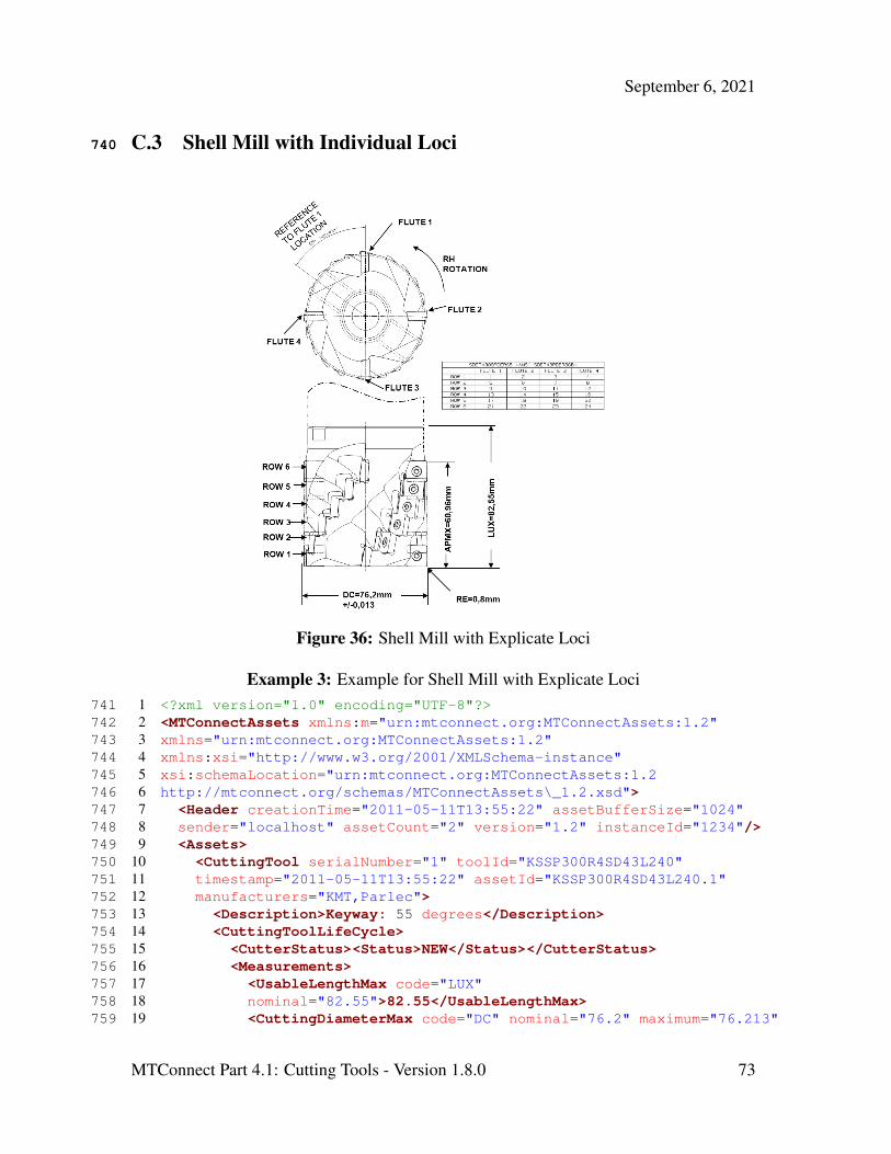
September 6, 2021
C.3 Shell Mill with Individual Loci740
Figure 36: Shell Mill with Explicate Loci
Example 3: Example for Shell Mill with Explicate Loci1 <?xml version="1.0" encoding="UTF-8"?>7412 <MTConnectAssets xmlns:m="urn:mtconnect.org:MTConnectAssets:1.2"7423 xmlns="urn:mtconnect.org:MTConnectAssets:1.2"7434 xmlns:xsi="http://www.w3.org/2001/XMLSchema-instance"7445 xsi:schemaLocation="urn:mtconnect.org:MTConnectAssets:1.27456 http://mtconnect.org/schemas/MTConnectAssets\_1.2.xsd">7467 <Header creationTime="2011-05-11T13:55:22" assetBufferSize="1024"7478 sender="localhost" assetCount="2" version="1.2" instanceId="1234"/>7489 <Assets>749
10 <CuttingTool serialNumber="1" toolId="KSSP300R4SD43L240"75011 timestamp="2011-05-11T13:55:22" assetId="KSSP300R4SD43L240.1"75112 manufacturers="KMT,Parlec">75213 <Description>Keyway: 55 degrees</Description>75314 <CuttingToolLifeCycle>75415 <CutterStatus><Status>NEW</Status></CutterStatus>75516 <Measurements>75617 <UsableLengthMax code="LUX"75718 nominal="82.55">82.55</UsableLengthMax>75819 <CuttingDiameterMax code="DC" nominal="76.2" maximum="76.213"759
MTConnect Part 4.1: Cutting Tools - Version 1.8.0 73
September 6, 2021
20 minimum="76.187">76.2</CuttingDiameterMax>76021 <DepthOfCutMax code="APMX" nominal="60.96">60.95</DepthOfCutMax>76122 </Measurements>76223 <CuttingItems count="24">76324 <CuttingItem indices="1" itemId="SDET43PDER8GB"76425 manufacturers="KMT">76526 <Locus>FLUTE: 1, ROW: 1</Locus>76627 <Measurements>76728 <DriveAngle code="DRVA" nominal="55">55</DriveAngle>76829 </Measurements>76930 </CuttingItem>77031 <CuttingItem indices="2-24" itemId="SDET43PDER8GB"77132 manufacturers="KMT">77233 <Locus>FLUTE: 2-4, ROW: 1; FLUTE: 1-4, ROW 2-6</Locus>77334 </CuttingItem>77435 </CuttingItems>77536 </CuttingToolLifeCycle>77637 </CuttingTool>77738 </Assets>77839 </MTConnectAssets>779
MTConnect Part 4.1: Cutting Tools - Version 1.8.0 74

September 6, 2021
C.4 Drill with Individual Loci780
Figure 37: Step Drill with Explicate Loci
Example 4: Example for Step Drill with Explicate Loci1 <?xml version="1.0" encoding="UTF-8"?>7812 <MTConnectAssets xmlns:m="urn:mtconnect.org:MTConnectAssets:1.2"7823 xmlns="urn:mtconnect.org:MTConnectAssets:1.2"7834 xmlns:xsi="http://www.w3.org/2001/XMLSchema-instance"7845 xsi:schemaLocation="urn:mtconnect.org:MTConnectAssets:1.27856 http://mtconnect.org/schemas/MTConnectAssets\_1.2.xsd">7867 <Header creationTime="2011-05-11T13:55:22" assetBufferSize="1024"7878 sender="localhost" assetCount="2" version="1.2" instanceId="1234"/>7889 <Assets>789
10 <CuttingTool serialNumber="1" toolId="KSEM0781LD"79011 timestamp="2011-05-11T13:55:22" assetId="KSEM0781LD.1" manufacturers="KMT">79112 <CuttingToolLifeCycle>79213 <CutterStatus><Status>NEW</Status></CutterStatus>79314 <ConnectionCodeMachineSide>HSK63A</ConnectionCodeMachineSide>79415 <Measurements>79516 <BodyDiameterMax code="BDX">52.75</BodyDiameterMax>79617 <OverallToolLength nominal="172.29"797
MTConnect Part 4.1: Cutting Tools - Version 1.8.0 75

September 6, 2021
18 code="OAL">172.29</OverallToolLength>79819 <UsableLengthMax code="LUX" nominal="49">49</UsableLengthMax>79920 <FlangeDiameterMax code="DF"80021 nominal="62.94">62.94</FlangeDiameterMax>80122 </Measurements>80223 <CuttingItems count="3">80324 <CuttingItem indices="1" itemId="KSEM0781LD" manufacturers="KMT"80425 grade="KC7015">80526 <Locus>FLUTE: 1, ROW: 1</Locus>80627 <Measurements>80728 <FunctionalLength code="LF1" nominal="154.42">154.42</FunctionalLength>80829 <CuttingDiameter code="DC1" nominal="19.844">19.844</CuttingDiameter>80930 <PointAngle code="SIG" nominal="140">140</PointAngle>81031 <ToolCuttingEdgeAngle code="KAPR1" nominal="45">45</ToolCuttingEdgeAngle>81132 <StepDiameterLength code="SLD1" nominal="39.8">39.8</StepDiameterLength>81233 </Measurements>81334 </CuttingItem>81435 <CuttingItem indices="2-3" itemId="TPMT-21.52-FP"81536 manufacturers="KMT" grade="KCM15">81637 <Locus>FLUTE: 1-2, ROW: 2</Locus>81738 <Measurements>81839 <FunctionalLength code="LF2" nominal="112.9">119.2</FunctionalLength>81940 <CuttingDiameter code="DC2" nominal="31">31</CuttingDiameter>82041 </Measurements>82142 </CuttingItem>82243 </CuttingItems>82344 </CuttingToolLifeCycle>82445 </CuttingTool>82546 </Assets>82647 </MTConnectAssets>827
MTConnect Part 4.1: Cutting Tools - Version 1.8.0 76
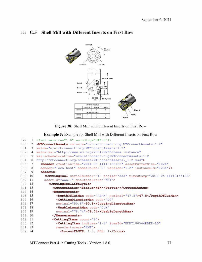
September 6, 2021
C.5 Shell Mill with Different Inserts on First Row828
Figure 38: Shell Mill with Different Inserts on First Row
Example 5: Example for Shell Mill with Different Inserts on First Row1 <?xml version="1.0" encoding="UTF-8"?>8292 <MTConnectAssets xmlns:m="urn:mtconnect.org:MTConnectAssets:1.2"8303 xmlns="urn:mtconnect.org:MTConnectAssets:1.2"8314 xmlns:xsi="http://www.w3.org/2001/XMLSchema-instance"8325 xsi:schemaLocation="urn:mtconnect.org:MTConnectAssets:1.28336 http://mtconnect.org/schemas/MTConnectAssets\_1.2.xsd">8347 <Header creationTime="2011-05-11T13:55:22" assetBufferSize="1024"8358 sender="localhost" assetCount="2" version="1.2" instanceId="1234"/>8369 <Assets>837
10 <CuttingTool serialNumber="1" toolId="XXX" timestamp="2011-05-11T13:55:22"83811 assetId="XXX.1" manufacturers="KMT">83912 <CuttingToolLifeCycle>84013 <CutterStatus><Status>NEW</Status></CutterStatus>84114 <Measurements>84215 <DepthOfCutMax code="APMX" nominal="47.8">47.8</DepthOfCutMax>84316 <CuttingDiameterMax code="DC"84417 nominal="50.8">50.8</CuttingDiameterMax>84518 <UsableLengthMax code="LUX"84619 nominal="78.74">78.74</UsableLengthMax>84720 </Measurements>84821 <CuttingItems count="9">84922 <CuttingItem indices="1-3" itemId="EDPT180564PDER-LD"85023 manufacturers="KMT">85124 <Locus>FLUTE: 1-3, ROW: 1</Locus>852
MTConnect Part 4.1: Cutting Tools - Version 1.8.0 77

September 6, 2021
25 <Measurements>85326 <CornerRadius code="RE" nominal="6.25">6.35</CornerRadius>85427 </Measurements>85528 </CuttingItem>85629 <CuttingItem indices="4-9" itemId="EDPT180508PDER-LD"85730 manufacturers="KMT">85831 <Locus>FLANGE: 1-4, ROW: 2-3</Locus>85932 </CuttingItem>86033 </CuttingItems>86134 </CuttingToolLifeCycle>86235 </CuttingTool>86336 </Assets>86437 </MTConnectAssets>865
MTConnect Part 4.1: Cutting Tools - Version 1.8.0 78