mtx 75 transmission - dismantle and assemble (16 118 8) · «escort 1991/1996 table of contents»...
TRANSCRIPT
«Escort 1991/1996 Table of Contents»«Group 16: Manual Transmission and Clutch»«Section 16-03: MTX 75 Manual Transmission and Clutch»«REMOVAL AND INSTALLATION»
MTX 75 Transmission - Dismantle and Assemble (16 118 8)
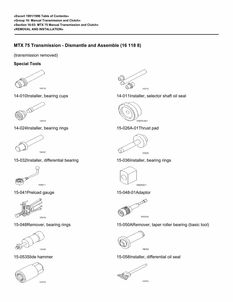
(transmission removed) Special Tools
14-010Installer, bearing cups 14-011Installer, selector shaft oil seal
14-024Installer, bearing rings 15-026A-01Thrust pad
15-032Installer, differential bearing 15-036Installer, bearing rings
15-041Preload gauge 15-048-01Adaptor
15-048Remover, bearing rings 15-050ARemover, taper roller bearing (basic tool)
15-053Slide hammer 15-058Installer, differential oil seal

15-073Socket 15-074Remover, bearing rings
16-019Remover/installer, selector shaft oil seal 16-058Mounting plate, transmission
16-059Measuring fixture, end float output shaft 16-060Collet for 15-050A
16-061Collet for 15-050A 16-062Collet for 15-050A
16-063Pressure plate, gear wheel removal 16-074Remover, driveshaft oil seal
21-024-02Adaptor for 21-024 21-024-07Adaptor for 21-024
21-024Valve spring compressor 21-031 BMounting bracket, transmission
21-103ARemover/installer, selector shaft ball sleeves Proprietary Tools
⁄ƒƒƒƒƒƒƒƒƒƒƒƒƒƒƒƒƒƒƒƒƒƒƒƒƒƒƒƒƒƒƒƒƒƒƒƒƒƒƒƒƒƒƒƒƒƒƒƒƒƒƒƒƒƒƒƒƒƒƒƒƒƒƒƒƒƒƒƒƒƒƒƒƒƒƒƒƒƒƒƒƒƒƒƒø
≥ Magnetic fixture ≥
√ƒƒƒƒƒƒƒƒƒƒƒƒƒƒƒƒƒƒƒƒƒƒƒƒƒƒƒƒƒƒƒƒƒƒƒƒƒƒƒƒƒƒƒƒƒƒƒƒƒƒƒƒƒƒƒƒƒƒƒƒƒƒƒƒƒƒƒƒƒƒƒƒƒƒƒƒƒƒƒƒƒƒƒƒ¥
≥ Dial gauge ≥
√ƒƒƒƒƒƒƒƒƒƒƒƒƒƒƒƒƒƒƒƒƒƒƒƒƒƒƒƒƒƒƒƒƒƒƒƒƒƒƒƒƒƒƒƒƒƒƒƒƒƒƒƒƒƒƒƒƒƒƒƒƒƒƒƒƒƒƒƒƒƒƒƒƒƒƒƒƒƒƒƒƒƒƒƒ¥
≥ Hot air fan ≥
¿ƒƒƒƒƒƒƒƒƒƒƒƒƒƒƒƒƒƒƒƒƒƒƒƒƒƒƒƒƒƒƒƒƒƒƒƒƒƒƒƒƒƒƒƒƒƒƒƒƒƒƒƒƒƒƒƒƒƒƒƒƒƒƒƒƒƒƒƒƒƒƒƒƒƒƒƒƒƒƒƒƒƒƒƒŸ
Workshop Equipment

⁄ƒƒƒƒƒƒƒƒƒƒƒƒƒƒƒƒƒƒƒƒƒƒƒƒƒƒƒƒƒƒƒƒƒƒƒƒƒƒƒƒƒ¬ƒƒƒƒƒƒƒƒƒƒƒƒƒƒƒƒƒƒƒƒƒƒƒƒƒƒƒƒƒƒƒƒƒƒƒƒƒƒƒƒƒø
≥ Press ≥ ≥
¿ƒƒƒƒƒƒƒƒƒƒƒƒƒƒƒƒƒƒƒƒƒƒƒƒƒƒƒƒƒƒƒƒƒƒƒƒƒƒƒƒƒ¡ƒƒƒƒƒƒƒƒƒƒƒƒƒƒƒƒƒƒƒƒƒƒƒƒƒƒƒƒƒƒƒƒƒƒƒƒƒƒƒƒƒŸ
Materials
⁄ƒƒƒƒƒƒƒƒƒƒƒƒƒƒƒƒƒƒƒƒƒƒƒƒƒƒƒƒƒƒƒƒƒƒƒƒƒƒƒƒƒ¬ƒƒƒƒƒƒƒƒƒƒƒƒƒƒƒƒƒƒƒƒƒƒƒƒƒƒƒƒƒƒƒƒƒƒƒƒƒƒƒƒƒø
≥ High-temperature grease ≥ ESD-M1C220-A ≥
√ƒƒƒƒƒƒƒƒƒƒƒƒƒƒƒƒƒƒƒƒƒƒƒƒƒƒƒƒƒƒƒƒƒƒƒƒƒƒƒƒƒ≈ƒƒƒƒƒƒƒƒƒƒƒƒƒƒƒƒƒƒƒƒƒƒƒƒƒƒƒƒƒƒƒƒƒƒƒƒƒƒƒƒƒ¥
≥ Sealer ≥ WSK-M2G348-A5 ≥
√ƒƒƒƒƒƒƒƒƒƒƒƒƒƒƒƒƒƒƒƒƒƒƒƒƒƒƒƒƒƒƒƒƒƒƒƒƒƒƒƒƒ≈ƒƒƒƒƒƒƒƒƒƒƒƒƒƒƒƒƒƒƒƒƒƒƒƒƒƒƒƒƒƒƒƒƒƒƒƒƒƒƒƒƒ¥
≥ Transmission fluid (ATF) ≥ ESD-M2C186-A ≥
√ƒƒƒƒƒƒƒƒƒƒƒƒƒƒƒƒƒƒƒƒƒƒƒƒƒƒƒƒƒƒƒƒƒƒƒƒƒƒƒƒƒ≈ƒƒƒƒƒƒƒƒƒƒƒƒƒƒƒƒƒƒƒƒƒƒƒƒƒƒƒƒƒƒƒƒƒƒƒƒƒƒƒƒƒ¥
≥ Freezing spray ≥ ≥
¿ƒƒƒƒƒƒƒƒƒƒƒƒƒƒƒƒƒƒƒƒƒƒƒƒƒƒƒƒƒƒƒƒƒƒƒƒƒƒƒƒƒ¡ƒƒƒƒƒƒƒƒƒƒƒƒƒƒƒƒƒƒƒƒƒƒƒƒƒƒƒƒƒƒƒƒƒƒƒƒƒƒƒƒƒŸ
Measuring and Adjusting Shims
⁄ƒƒƒƒƒƒƒƒƒƒƒƒƒƒƒƒƒƒƒƒƒƒƒƒƒƒƒƒƒƒƒƒƒƒƒƒƒƒƒƒƒƒ¬ƒƒƒƒƒƒƒƒƒƒƒƒƒƒƒƒƒƒƒƒƒƒ¬ƒƒƒƒƒƒƒƒƒƒƒƒƒƒƒƒƒƒƒƒƒƒ¬ƒƒƒƒƒƒƒƒƒƒƒƒƒƒƒƒƒƒƒƒƒƒ
≥ ≥ Input Shaft ≥ Output Shaft ≥ Differential
√ƒƒƒƒƒƒƒƒƒƒƒƒƒƒƒƒƒƒƒƒƒƒƒƒƒƒƒƒƒƒƒƒƒƒƒƒƒƒƒƒƒƒ≈ƒƒƒƒƒƒƒƒƒƒƒƒƒƒƒƒƒƒƒƒƒƒ≈ƒƒƒƒƒƒƒƒƒƒƒƒƒƒƒƒƒƒƒƒƒƒ≈ƒƒƒƒƒƒƒƒƒƒƒƒƒƒƒƒƒƒƒƒƒƒ
≥ Measuring shim in mm ≥ 1,00 ≥ 1,00 ≥ 1,10
√ƒƒƒƒƒƒƒƒƒƒƒƒƒƒƒƒƒƒƒƒƒƒƒƒƒƒƒƒƒƒƒƒƒƒƒƒƒƒƒƒƒƒ≈ƒƒƒƒƒƒƒƒƒƒƒƒƒƒƒƒƒƒƒƒƒƒ≈ƒƒƒƒƒƒƒƒƒƒƒƒƒƒƒƒƒƒƒƒƒƒ≈ƒƒƒƒƒƒƒƒƒƒƒƒƒƒƒƒƒƒƒƒƒƒ
≥ Adjustment shim availability (mm) ≥ 1,15 - 1,71 ≥ 1,31 - 1,91 ≥ 1,40 -- 2,20
¿ƒƒƒƒƒƒƒƒƒƒƒƒƒƒƒƒƒƒƒƒƒƒƒƒƒƒƒƒƒƒƒƒƒƒƒƒƒƒƒƒƒƒ¡ƒƒƒƒƒƒƒƒƒƒƒƒƒƒƒƒƒƒƒƒƒƒ¡ƒƒƒƒƒƒƒƒƒƒƒƒƒƒƒƒƒƒƒƒƒƒ¡ƒƒƒƒƒƒƒƒƒƒƒƒƒƒƒƒƒƒƒƒƒƒ
Transmission - Dismantle
µ 1. Detach the clutch release lever.
1 Undo the bolt and pull off the lever.2 Withdraw the gaiter and the bearing bush from above.
µ 2. Fit Special Tools.

µ 3. Remove the selector mechanism.
Put the transmission in neutral.Undo the six bolts.Remove the complete selector mechanism assembly.
µ 4. Remove the thrust bearing and the release shaft.
µ 5. Remove the guide sleeve.
1 Undo the three bolts.2 Twist the guide sleeve and prise off.

µ 6. Remove the driveshaft oil seals with the Special Tool.
µ 7. Detach the speedometer drive pinion.
1 Pull out the roll pin.2 Pull out of drive pinion.
Detach the selector shaft oil seal.
µ 8. Pull off the oil seal using the special tool.
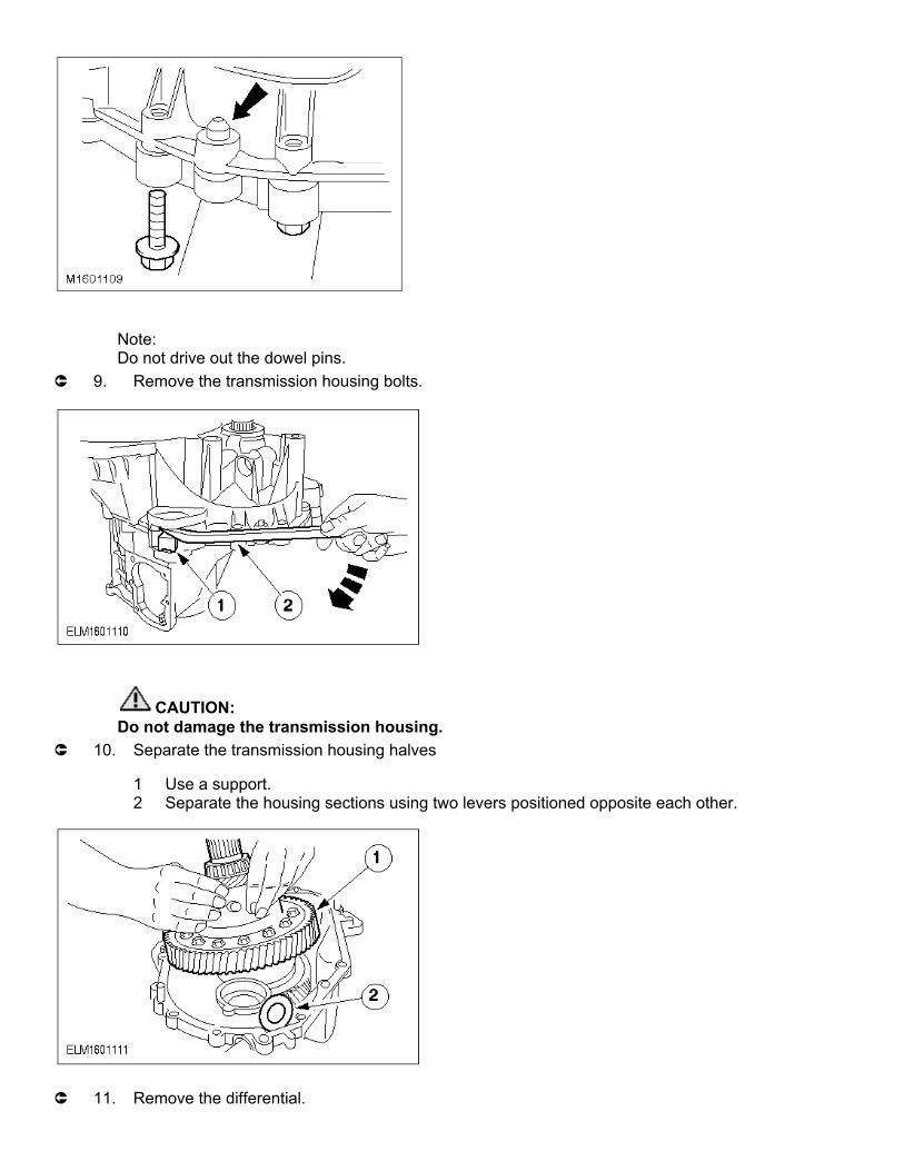
Note:Do not drive out the dowel pins.
µ 9. Remove the transmission housing bolts.
CAUTION:Do not damage the transmission housing.
µ 10. Separate the transmission housing halves
1 Use a support.2 Separate the housing sections using two levers positioned opposite each other.
µ 11. Remove the differential.

1 Lift out the complete differential assembly.2 Take out the magnetic disc.
µ 12. Remove the first/second gear selector rods and selector fork.
1 Remove the selector rods.2 Remove the first/second gear selector fork.
µ 13. Remove the first/second gear selector forks.
1 Swivel the fifth/reverse gear selector fork to one side.2 Turn the third/fourth gear selector fork and remove it.
Remove the fifth/reverse gear selector fork.
µ 14. Remove the reverse gear idler.

1 Detach the circlip.Tilt the input and output shafts to the side.2 Remove the reverse gear idler by pulling it upwards (see following step for removal sequence).
µ 15. Removal sequence for removing the reverse gear idler.
1 Circlip2 Upper thrust washer3 Reverse gear idler4 Needle roller bearing5 Lower thrust washer
µ 16. Remove the input and output shafts.
Lift the input and output shafts together out of the transmission housing.Take out the mounting block and reverse idler gear together with the needle roller bearing and thrust washers.

µ 17. Remove the selector shaft.
1 Undo the ball socket and take off the selector shaft.2 Pull off the selector shaft.
µ 18. Remove the selector shaft ball sleeves.
µ 19. Remove the inner selector shaft bearing bush.

Remove the bearing rings.
Note:Fit the special tool in the transmission recesses.
µ 20. Take off the differential bearing ring.
Note:Fit the special tool in the transmission recesses.
µ 21. Remove the bearings rings from the input and output shafts.
Note:Fit the special tool in the transmission recesses.

µ 22. Remove the differential and the bearing rings.
From the input shaftFrom the differential
Note:Fit the special tool in the transmission recesses.
µ 23. Remove the input shaft bearing ring and the shim.
Note:Only carry out if there is damage or leaks.
µ 24. Remove the reverse gear idler shaft.

Note:See previous step.
µ 25. Drive out the reverse gear idler shaft with a block of hardwood.
Dismantle the differential.
µ 26. Pull the taper roller bearing off the differential.
1 Insert the thrust pad.2 Pull off the taper roller bearing.Detach the speedometer worm gear.
µ 27. Detach the crown wheel.
Note:Use a copper hammer.Unscrew the retaining bolts and separate the crown wheel from the differential cage by tapping
lightly.
28. General note.
Note:From model year '95 a double synchroniser is installed for 1st, 2nd and 3rd gears. The layout and assembly of the single synchroniser for third gear is identical to that for fourth gear. The steps described below refer to the double synchroniser. Refer to the Technical Data table for renewal of synchroniser parts.

CAUTION:The inner synchroniser ring and the synchroniser cone must be handled with great care.The layout and assembly of the single synchroniser for 3rd gear is identical to that for 4th gear. The
steps described below refer to the double synchroniser. Refer to the Technical Data table for renewal of synchroniser parts.
Layout of the input shaft
⁄ƒƒƒƒƒƒƒƒƒƒƒƒƒƒƒ¬ƒƒƒƒƒƒƒƒƒƒƒƒƒƒƒƒƒƒƒƒƒƒƒƒƒƒƒƒƒƒƒƒƒƒƒƒƒƒƒƒƒƒƒƒƒƒƒƒƒƒƒƒƒƒƒƒƒƒƒƒƒƒƒƒƒƒƒø
≥ Item ≥ Description ≥
√ƒƒƒƒƒƒƒƒƒƒƒƒƒƒƒ≈ƒƒƒƒƒƒƒƒƒƒƒƒƒƒƒƒƒƒƒƒƒƒƒƒƒƒƒƒƒƒƒƒƒƒƒƒƒƒƒƒƒƒƒƒƒƒƒƒƒƒƒƒƒƒƒƒƒƒƒƒƒƒƒƒƒƒƒ¥
≥ 1 ≥ Taper roller bearing on the clutch side. ≥
√ƒƒƒƒƒƒƒƒƒƒƒƒƒƒƒ≈ƒƒƒƒƒƒƒƒƒƒƒƒƒƒƒƒƒƒƒƒƒƒƒƒƒƒƒƒƒƒƒƒƒƒƒƒƒƒƒƒƒƒƒƒƒƒƒƒƒƒƒƒƒƒƒƒƒƒƒƒƒƒƒƒƒƒƒ¥
≥ 2 ≥ Input shaft ≥
√ƒƒƒƒƒƒƒƒƒƒƒƒƒƒƒ≈ƒƒƒƒƒƒƒƒƒƒƒƒƒƒƒƒƒƒƒƒƒƒƒƒƒƒƒƒƒƒƒƒƒƒƒƒƒƒƒƒƒƒƒƒƒƒƒƒƒƒƒƒƒƒƒƒƒƒƒƒƒƒƒƒƒƒƒ¥
≥ 3 ≥ Needle roller bearing - third gear wheel ≥
√ƒƒƒƒƒƒƒƒƒƒƒƒƒƒƒ≈ƒƒƒƒƒƒƒƒƒƒƒƒƒƒƒƒƒƒƒƒƒƒƒƒƒƒƒƒƒƒƒƒƒƒƒƒƒƒƒƒƒƒƒƒƒƒƒƒƒƒƒƒƒƒƒƒƒƒƒƒƒƒƒƒƒƒƒ¥
≥ 4 ≥ 3rd gear wheel ≥
√ƒƒƒƒƒƒƒƒƒƒƒƒƒƒƒ≈ƒƒƒƒƒƒƒƒƒƒƒƒƒƒƒƒƒƒƒƒƒƒƒƒƒƒƒƒƒƒƒƒƒƒƒƒƒƒƒƒƒƒƒƒƒƒƒƒƒƒƒƒƒƒƒƒƒƒƒƒƒƒƒƒƒƒƒ¥
≥ 5 ≥ 3rd gear inner synchroniser ring ≥
√ƒƒƒƒƒƒƒƒƒƒƒƒƒƒƒ≈ƒƒƒƒƒƒƒƒƒƒƒƒƒƒƒƒƒƒƒƒƒƒƒƒƒƒƒƒƒƒƒƒƒƒƒƒƒƒƒƒƒƒƒƒƒƒƒƒƒƒƒƒƒƒƒƒƒƒƒƒƒƒƒƒƒƒƒ¥
≥ 6 ≥ 3rd gear synchroniser cone ≥
√ƒƒƒƒƒƒƒƒƒƒƒƒƒƒƒ≈ƒƒƒƒƒƒƒƒƒƒƒƒƒƒƒƒƒƒƒƒƒƒƒƒƒƒƒƒƒƒƒƒƒƒƒƒƒƒƒƒƒƒƒƒƒƒƒƒƒƒƒƒƒƒƒƒƒƒƒƒƒƒƒƒƒƒƒ¥
≥ 7 ≥ 3rd gear outer synchroniser ring ≥
√ƒƒƒƒƒƒƒƒƒƒƒƒƒƒƒ≈ƒƒƒƒƒƒƒƒƒƒƒƒƒƒƒƒƒƒƒƒƒƒƒƒƒƒƒƒƒƒƒƒƒƒƒƒƒƒƒƒƒƒƒƒƒƒƒƒƒƒƒƒƒƒƒƒƒƒƒƒƒƒƒƒƒƒƒ¥
≥ 8 ≥ 3rd/4th gear synchroniser assembly ≥
√ƒƒƒƒƒƒƒƒƒƒƒƒƒƒƒ≈ƒƒƒƒƒƒƒƒƒƒƒƒƒƒƒƒƒƒƒƒƒƒƒƒƒƒƒƒƒƒƒƒƒƒƒƒƒƒƒƒƒƒƒƒƒƒƒƒƒƒƒƒƒƒƒƒƒƒƒƒƒƒƒƒƒƒƒ¥
≥ 9 ≥ Circlip ≥

√ƒƒƒƒƒƒƒƒƒƒƒƒƒƒƒ≈ƒƒƒƒƒƒƒƒƒƒƒƒƒƒƒƒƒƒƒƒƒƒƒƒƒƒƒƒƒƒƒƒƒƒƒƒƒƒƒƒƒƒƒƒƒƒƒƒƒƒƒƒƒƒƒƒƒƒƒƒƒƒƒƒƒƒƒ¥
≥ 10 ≥ 4th gear synchroniser ring ≥
√ƒƒƒƒƒƒƒƒƒƒƒƒƒƒƒ≈ƒƒƒƒƒƒƒƒƒƒƒƒƒƒƒƒƒƒƒƒƒƒƒƒƒƒƒƒƒƒƒƒƒƒƒƒƒƒƒƒƒƒƒƒƒƒƒƒƒƒƒƒƒƒƒƒƒƒƒƒƒƒƒƒƒƒƒ¥
≥ 11 ≥ Needle roller bearing for 4th gear ≥
√ƒƒƒƒƒƒƒƒƒƒƒƒƒƒƒ≈ƒƒƒƒƒƒƒƒƒƒƒƒƒƒƒƒƒƒƒƒƒƒƒƒƒƒƒƒƒƒƒƒƒƒƒƒƒƒƒƒƒƒƒƒƒƒƒƒƒƒƒƒƒƒƒƒƒƒƒƒƒƒƒƒƒƒƒ¥
≥ 12 ≥ 4th gear wheel ≥
√ƒƒƒƒƒƒƒƒƒƒƒƒƒƒƒ≈ƒƒƒƒƒƒƒƒƒƒƒƒƒƒƒƒƒƒƒƒƒƒƒƒƒƒƒƒƒƒƒƒƒƒƒƒƒƒƒƒƒƒƒƒƒƒƒƒƒƒƒƒƒƒƒƒƒƒƒƒƒƒƒƒƒƒƒ¥
≥ 13 ≥ 5th gear wheel ≥
√ƒƒƒƒƒƒƒƒƒƒƒƒƒƒƒ≈ƒƒƒƒƒƒƒƒƒƒƒƒƒƒƒƒƒƒƒƒƒƒƒƒƒƒƒƒƒƒƒƒƒƒƒƒƒƒƒƒƒƒƒƒƒƒƒƒƒƒƒƒƒƒƒƒƒƒƒƒƒƒƒƒƒƒƒ¥
≥ 14 ≥ Circlip ≥
√ƒƒƒƒƒƒƒƒƒƒƒƒƒƒƒ≈ƒƒƒƒƒƒƒƒƒƒƒƒƒƒƒƒƒƒƒƒƒƒƒƒƒƒƒƒƒƒƒƒƒƒƒƒƒƒƒƒƒƒƒƒƒƒƒƒƒƒƒƒƒƒƒƒƒƒƒƒƒƒƒƒƒƒƒ¥
≥ 15 ≥ Taper roller bearing on the transmission side ≥
¿ƒƒƒƒƒƒƒƒƒƒƒƒƒƒƒ¡ƒƒƒƒƒƒƒƒƒƒƒƒƒƒƒƒƒƒƒƒƒƒƒƒƒƒƒƒƒƒƒƒƒƒƒƒƒƒƒƒƒƒƒƒƒƒƒƒƒƒƒƒƒƒƒƒƒƒƒƒƒƒƒƒƒƒƒŸ
Dismantle input shaft
Note:Taper roller bearing and fifth gear wheel can also be pressed off together (see following step).
µ 29. Pull off the taper roller bearing on the transmission side.
µ 30. Press off the fifth gear wheel together with the taper roller bearing.
1 Move the circlip upwards out of the annular groove up to the taper roller bearing.2 Press off the gear wheel together with the circlip and the taper roller bearing.

µ 31. Detach the fourth gear wheel together with needle roller bearing and synchroniser ring.
1 Gear wheel2 Needle roller bearing3 Synchroniser ring
µ 32. Detach the 3rd/4th gear synchroniser assembly.
1 Circlip2 Gear synchroniser
CAUTION:Carefully pull the selector ring off the gear synchroniser hub; the detent balls are
spring-tensioned.

Note:Mark the installation location of the selector ring.
µ 33. Dismantle the gear synchroniser.
1 Selector ring2 Gear synchroniser hub3 Compression spring4 Blocker bar5 Detent ball
µ 34. Detach third gear wheel together with the double synchroniser.
1 Outer synchroniser ring2 Synchroniser cone3 Inner synchroniser ring4 Gear wheel5 Needle roller bearing
µ 35. Pull the taper roller bearing on the clutch side off the input shaft.
36. General note.
Note:From model year '95 a double synchroniser is installed for 1st, 2nd and 3rd gears. The layout and assembly of the single synchroniser for third gear is identical to that for fourth gear. The steps described below refer to the double synchroniser. Refer to the Technical Data table for renewal of synchroniser parts.

CAUTION:The inner synchroniser ring and the synchroniser cone must be handled with great care.The layout and assembly of the single synchroniser for 3rd gear is identical to that for 4th gear. The
steps described below refer to the double synchroniser. Refer to the Technical Data table for renewal of synchroniser parts.
Layout of output shaft
⁄ƒƒƒƒƒƒƒƒƒƒƒƒƒƒƒ¬ƒƒƒƒƒƒƒƒƒƒƒƒƒƒƒƒƒƒƒƒƒƒƒƒƒƒƒƒƒƒƒƒƒƒƒƒƒƒƒƒƒƒƒƒƒƒƒƒƒƒƒƒƒƒƒƒƒƒƒƒƒƒƒƒƒƒƒø
≥ Item ≥ Description ≥
√ƒƒƒƒƒƒƒƒƒƒƒƒƒƒƒ≈ƒƒƒƒƒƒƒƒƒƒƒƒƒƒƒƒƒƒƒƒƒƒƒƒƒƒƒƒƒƒƒƒƒƒƒƒƒƒƒƒƒƒƒƒƒƒƒƒƒƒƒƒƒƒƒƒƒƒƒƒƒƒƒƒƒƒƒ¥
≥ 1 ≥ 3rd gear wheel ≥
√ƒƒƒƒƒƒƒƒƒƒƒƒƒƒƒ≈ƒƒƒƒƒƒƒƒƒƒƒƒƒƒƒƒƒƒƒƒƒƒƒƒƒƒƒƒƒƒƒƒƒƒƒƒƒƒƒƒƒƒƒƒƒƒƒƒƒƒƒƒƒƒƒƒƒƒƒƒƒƒƒƒƒƒƒ¥
≥ 2 ≥ 4th gear wheel ≥
√ƒƒƒƒƒƒƒƒƒƒƒƒƒƒƒ≈ƒƒƒƒƒƒƒƒƒƒƒƒƒƒƒƒƒƒƒƒƒƒƒƒƒƒƒƒƒƒƒƒƒƒƒƒƒƒƒƒƒƒƒƒƒƒƒƒƒƒƒƒƒƒƒƒƒƒƒƒƒƒƒƒƒƒƒ¥
≥ 3 ≥ 4th gear needle roller bearing ≥
√ƒƒƒƒƒƒƒƒƒƒƒƒƒƒƒ≈ƒƒƒƒƒƒƒƒƒƒƒƒƒƒƒƒƒƒƒƒƒƒƒƒƒƒƒƒƒƒƒƒƒƒƒƒƒƒƒƒƒƒƒƒƒƒƒƒƒƒƒƒƒƒƒƒƒƒƒƒƒƒƒƒƒƒƒ¥
≥ 4 ≥ 5th gear wheel ≥
√ƒƒƒƒƒƒƒƒƒƒƒƒƒƒƒ≈ƒƒƒƒƒƒƒƒƒƒƒƒƒƒƒƒƒƒƒƒƒƒƒƒƒƒƒƒƒƒƒƒƒƒƒƒƒƒƒƒƒƒƒƒƒƒƒƒƒƒƒƒƒƒƒƒƒƒƒƒƒƒƒƒƒƒƒ¥
≥ 5 ≥ 5th gear synchroniser ring ≥
√ƒƒƒƒƒƒƒƒƒƒƒƒƒƒƒ≈ƒƒƒƒƒƒƒƒƒƒƒƒƒƒƒƒƒƒƒƒƒƒƒƒƒƒƒƒƒƒƒƒƒƒƒƒƒƒƒƒƒƒƒƒƒƒƒƒƒƒƒƒƒƒƒƒƒƒƒƒƒƒƒƒƒƒƒ¥
≥ 6 ≥ Fifth/reverse gear synchroniser, complete ≥
√ƒƒƒƒƒƒƒƒƒƒƒƒƒƒƒ≈ƒƒƒƒƒƒƒƒƒƒƒƒƒƒƒƒƒƒƒƒƒƒƒƒƒƒƒƒƒƒƒƒƒƒƒƒƒƒƒƒƒƒƒƒƒƒƒƒƒƒƒƒƒƒƒƒƒƒƒƒƒƒƒƒƒƒƒ¥
≥ 7 ≥ Circlip ≥
√ƒƒƒƒƒƒƒƒƒƒƒƒƒƒƒ≈ƒƒƒƒƒƒƒƒƒƒƒƒƒƒƒƒƒƒƒƒƒƒƒƒƒƒƒƒƒƒƒƒƒƒƒƒƒƒƒƒƒƒƒƒƒƒƒƒƒƒƒƒƒƒƒƒƒƒƒƒƒƒƒƒƒƒƒ¥
≥ 8 ≥ Reverse synchroniser ring ≥
√ƒƒƒƒƒƒƒƒƒƒƒƒƒƒƒ≈ƒƒƒƒƒƒƒƒƒƒƒƒƒƒƒƒƒƒƒƒƒƒƒƒƒƒƒƒƒƒƒƒƒƒƒƒƒƒƒƒƒƒƒƒƒƒƒƒƒƒƒƒƒƒƒƒƒƒƒƒƒƒƒƒƒƒƒ¥

≥ 9 ≥ Reverse gear needle roller bearing ≥
√ƒƒƒƒƒƒƒƒƒƒƒƒƒƒƒ≈ƒƒƒƒƒƒƒƒƒƒƒƒƒƒƒƒƒƒƒƒƒƒƒƒƒƒƒƒƒƒƒƒƒƒƒƒƒƒƒƒƒƒƒƒƒƒƒƒƒƒƒƒƒƒƒƒƒƒƒƒƒƒƒƒƒƒƒ¥
≥ 10 ≥ Reverse gearwheel ≥
√ƒƒƒƒƒƒƒƒƒƒƒƒƒƒƒ≈ƒƒƒƒƒƒƒƒƒƒƒƒƒƒƒƒƒƒƒƒƒƒƒƒƒƒƒƒƒƒƒƒƒƒƒƒƒƒƒƒƒƒƒƒƒƒƒƒƒƒƒƒƒƒƒƒƒƒƒƒƒƒƒƒƒƒƒ¥
≥ 11 ≥ Taper roller bearing on the transmission side. ≥
¿ƒƒƒƒƒƒƒƒƒƒƒƒƒƒƒ¡ƒƒƒƒƒƒƒƒƒƒƒƒƒƒƒƒƒƒƒƒƒƒƒƒƒƒƒƒƒƒƒƒƒƒƒƒƒƒƒƒƒƒƒƒƒƒƒƒƒƒƒƒƒƒƒƒƒƒƒƒƒƒƒƒƒƒƒŸ
Dismantle output shaft
Note:Taper roller bearing and reverse gear wheel can also be pressed off together.
µ 37. Pull off the taper roller bearing on the transmission side.
µ 38. Detach the reverse gear wheel.
1 Gear wheel2 Needle roller bearing3 Synchroniser ring
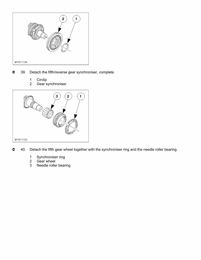
µ 39. Detach the fifth/reverse gear synchroniser, complete.
1 Circlip2 Gear synchroniser
µ 40. Detach the fifth gear wheel together with the synchroniser ring and the needle roller bearing.
1 Synchroniser ring2 Gear wheel3 Needle roller bearing

Layout of output shaft
⁄ƒƒƒƒƒƒƒƒƒƒƒƒƒƒƒ¬ƒƒƒƒƒƒƒƒƒƒƒƒƒƒƒƒƒƒƒƒƒƒƒƒƒƒƒƒƒƒƒƒƒƒƒƒƒƒƒƒƒƒƒƒƒƒƒƒƒƒƒƒƒƒƒƒƒƒƒƒƒƒƒƒƒƒƒø
≥ Item ≥ Description ≥
√ƒƒƒƒƒƒƒƒƒƒƒƒƒƒƒ≈ƒƒƒƒƒƒƒƒƒƒƒƒƒƒƒƒƒƒƒƒƒƒƒƒƒƒƒƒƒƒƒƒƒƒƒƒƒƒƒƒƒƒƒƒƒƒƒƒƒƒƒƒƒƒƒƒƒƒƒƒƒƒƒƒƒƒƒ¥
≥ 1 ≥ Output shaft ≥
√ƒƒƒƒƒƒƒƒƒƒƒƒƒƒƒ≈ƒƒƒƒƒƒƒƒƒƒƒƒƒƒƒƒƒƒƒƒƒƒƒƒƒƒƒƒƒƒƒƒƒƒƒƒƒƒƒƒƒƒƒƒƒƒƒƒƒƒƒƒƒƒƒƒƒƒƒƒƒƒƒƒƒƒƒ¥
≥ 2 ≥ 2nd gear needle roller bearing ≥
√ƒƒƒƒƒƒƒƒƒƒƒƒƒƒƒ≈ƒƒƒƒƒƒƒƒƒƒƒƒƒƒƒƒƒƒƒƒƒƒƒƒƒƒƒƒƒƒƒƒƒƒƒƒƒƒƒƒƒƒƒƒƒƒƒƒƒƒƒƒƒƒƒƒƒƒƒƒƒƒƒƒƒƒƒ¥
≥ 3 ≥ 2nd gear wheel ≥
√ƒƒƒƒƒƒƒƒƒƒƒƒƒƒƒ≈ƒƒƒƒƒƒƒƒƒƒƒƒƒƒƒƒƒƒƒƒƒƒƒƒƒƒƒƒƒƒƒƒƒƒƒƒƒƒƒƒƒƒƒƒƒƒƒƒƒƒƒƒƒƒƒƒƒƒƒƒƒƒƒƒƒƒƒ¥
≥ 4 ≥ 2nd gear inner synchroniser ring ≥
√ƒƒƒƒƒƒƒƒƒƒƒƒƒƒƒ≈ƒƒƒƒƒƒƒƒƒƒƒƒƒƒƒƒƒƒƒƒƒƒƒƒƒƒƒƒƒƒƒƒƒƒƒƒƒƒƒƒƒƒƒƒƒƒƒƒƒƒƒƒƒƒƒƒƒƒƒƒƒƒƒƒƒƒƒ¥

≥ 5 ≥ 2nd gear synchroniser cone ≥
√ƒƒƒƒƒƒƒƒƒƒƒƒƒƒƒ≈ƒƒƒƒƒƒƒƒƒƒƒƒƒƒƒƒƒƒƒƒƒƒƒƒƒƒƒƒƒƒƒƒƒƒƒƒƒƒƒƒƒƒƒƒƒƒƒƒƒƒƒƒƒƒƒƒƒƒƒƒƒƒƒƒƒƒƒ¥
≥ 6 ≥ 2nd gear outer synchroniser ring ≥
√ƒƒƒƒƒƒƒƒƒƒƒƒƒƒƒ≈ƒƒƒƒƒƒƒƒƒƒƒƒƒƒƒƒƒƒƒƒƒƒƒƒƒƒƒƒƒƒƒƒƒƒƒƒƒƒƒƒƒƒƒƒƒƒƒƒƒƒƒƒƒƒƒƒƒƒƒƒƒƒƒƒƒƒƒ¥
≥ 7 ≥ Gear synchroniser assembly (1st/2nd gear) ≥
√ƒƒƒƒƒƒƒƒƒƒƒƒƒƒƒ≈ƒƒƒƒƒƒƒƒƒƒƒƒƒƒƒƒƒƒƒƒƒƒƒƒƒƒƒƒƒƒƒƒƒƒƒƒƒƒƒƒƒƒƒƒƒƒƒƒƒƒƒƒƒƒƒƒƒƒƒƒƒƒƒƒƒƒƒ¥
≥ 8 ≥ Circlip ≥
√ƒƒƒƒƒƒƒƒƒƒƒƒƒƒƒ≈ƒƒƒƒƒƒƒƒƒƒƒƒƒƒƒƒƒƒƒƒƒƒƒƒƒƒƒƒƒƒƒƒƒƒƒƒƒƒƒƒƒƒƒƒƒƒƒƒƒƒƒƒƒƒƒƒƒƒƒƒƒƒƒƒƒƒƒ¥
≥ 9 ≥ 1st gear outer synchroniser ring ≥
√ƒƒƒƒƒƒƒƒƒƒƒƒƒƒƒ≈ƒƒƒƒƒƒƒƒƒƒƒƒƒƒƒƒƒƒƒƒƒƒƒƒƒƒƒƒƒƒƒƒƒƒƒƒƒƒƒƒƒƒƒƒƒƒƒƒƒƒƒƒƒƒƒƒƒƒƒƒƒƒƒƒƒƒƒ¥
≥ 10 ≥ 1st gear synchroniser cone ≥
√ƒƒƒƒƒƒƒƒƒƒƒƒƒƒƒ≈ƒƒƒƒƒƒƒƒƒƒƒƒƒƒƒƒƒƒƒƒƒƒƒƒƒƒƒƒƒƒƒƒƒƒƒƒƒƒƒƒƒƒƒƒƒƒƒƒƒƒƒƒƒƒƒƒƒƒƒƒƒƒƒƒƒƒƒ¥
≥ 11 ≥ 1st gear inner synchroniser ring ≥
√ƒƒƒƒƒƒƒƒƒƒƒƒƒƒƒ≈ƒƒƒƒƒƒƒƒƒƒƒƒƒƒƒƒƒƒƒƒƒƒƒƒƒƒƒƒƒƒƒƒƒƒƒƒƒƒƒƒƒƒƒƒƒƒƒƒƒƒƒƒƒƒƒƒƒƒƒƒƒƒƒƒƒƒƒ¥
≥ 12 ≥ 1st gear needle roller bearing ≥
√ƒƒƒƒƒƒƒƒƒƒƒƒƒƒƒ≈ƒƒƒƒƒƒƒƒƒƒƒƒƒƒƒƒƒƒƒƒƒƒƒƒƒƒƒƒƒƒƒƒƒƒƒƒƒƒƒƒƒƒƒƒƒƒƒƒƒƒƒƒƒƒƒƒƒƒƒƒƒƒƒƒƒƒƒ¥
≥ 13 ≥ 1st gear wheel ≥
√ƒƒƒƒƒƒƒƒƒƒƒƒƒƒƒ≈ƒƒƒƒƒƒƒƒƒƒƒƒƒƒƒƒƒƒƒƒƒƒƒƒƒƒƒƒƒƒƒƒƒƒƒƒƒƒƒƒƒƒƒƒƒƒƒƒƒƒƒƒƒƒƒƒƒƒƒƒƒƒƒƒƒƒƒ¥
≥ 14 ≥ Output pinion ≥
√ƒƒƒƒƒƒƒƒƒƒƒƒƒƒƒ≈ƒƒƒƒƒƒƒƒƒƒƒƒƒƒƒƒƒƒƒƒƒƒƒƒƒƒƒƒƒƒƒƒƒƒƒƒƒƒƒƒƒƒƒƒƒƒƒƒƒƒƒƒƒƒƒƒƒƒƒƒƒƒƒƒƒƒƒ¥
≥ 15 ≥ Circlip ≥
√ƒƒƒƒƒƒƒƒƒƒƒƒƒƒƒ≈ƒƒƒƒƒƒƒƒƒƒƒƒƒƒƒƒƒƒƒƒƒƒƒƒƒƒƒƒƒƒƒƒƒƒƒƒƒƒƒƒƒƒƒƒƒƒƒƒƒƒƒƒƒƒƒƒƒƒƒƒƒƒƒƒƒƒƒ¥
≥ 16 ≥ Taper roller bearing ≥
¿ƒƒƒƒƒƒƒƒƒƒƒƒƒƒƒ¡ƒƒƒƒƒƒƒƒƒƒƒƒƒƒƒƒƒƒƒƒƒƒƒƒƒƒƒƒƒƒƒƒƒƒƒƒƒƒƒƒƒƒƒƒƒƒƒƒƒƒƒƒƒƒƒƒƒƒƒƒƒƒƒƒƒƒƒŸ
µ 41. Pull off the taper roller bearing on the clutch side.
CAUTION:

Mark the output pinion for re-assembly. The output shaft and output pinion are paired and can be renewed together.
µ 42. Press the output pinion and the first gear wheel off together.
1 Circlip2 Pinion with first gear wheel.
µ 43. Detach the double synchroniser and the needle roller bearing together.
1 Needle roller bearing2 Inner synchroniser ring3 Synchroniser cone4 Outer synchroniser ring
µ 44. Remove the 1st/2nd gear synchroniser, complete.
1 Circlip2 Gear synchroniser

µ 45. Detach the second gear wheel.
1 Outer synchroniser ring2 Synchroniser cone3 Inner synchroniser ring4 Gear wheel5 Needle roller bearing
Note:Mark the installation position of the selector ring.
µ 46. Dismantle the gear synchroniser.
CAUTION:Carefully pull the selector ring off the gear synchroniser hub; the detent balls are spring-tensioned.1 Selector ring2 Gear synchroniser hub3 Compression spring4 Blocker bar5 Detent ball
Assemble
47. Carefully clean and check all parts before reassembly.

CAUTION:Immerse the double synchronisers transmission fluid (ESD-M2C186-A) and lubricate all moving parts.
µ 48. Install the selector shaft ball sleeves.
1 Insert the inner ball sleeve first.2 Drive in the ball sleeves using the special tool.
µ 49. Insert the inner selector shaft bearing sleeve.
µ 50. Install the selector shaft.
1 Install the selector shaft.

2 Locate the ball socket in position and tighten.
µ 51. Install the reverse gear idler shaft.
1 Apply sealer to the mating face of the reverse gear idler shaft.2 Locate the reverse gear idler shaft in position with the locating bolt and drive in.3 Remove the locating bolt and screw in the original bolts.
CAUTION:The pressure applied must not exceed 15 kN.
µ 52. Install the bearing rings on the transmission housing side.
Warm the housing locally with a hot-air blower to about 80ºC.Cool the bearing rings with a refrigerant spray and insert.Install the bearing rings using the press:Input shaft using 15-036Output shaft using 15-036Differential using 14-024
53. Shim of required thickness:
Input shaft: 1,00 mmOutput shaft: 1,00 mmDifferential: 1,10 mm

µ 54. Install the measuring shims and bearing rings from the clutch side of the transmission housing half.
Warm the housing locally to about 80ºC.Cool the bearing rings with refrigerant spray.
1 Insert the shims of the required thickness.2 Insert the bearing rings.
CAUTION:The pressure applied must not exceed 15 kN.
Note:Install using the press, do not drive it in.Bearing rings from:Input shaft using 14-010Output shaft using 15-036Differential using 14-024
Assemble differential
Note:Do not lubricate taper roller bearings that are to be re-used. New taper roller bearings can be installed
untreated. Carefully clean and check all parts and coat with transmission fluid before assembly.µ 55. Fit the crown wheel to the differential.
Tighten the crown wheel evenly, working diagonally.

Note:The speedometer worm gear or the sensor ring of the vehicle speed sensor must engage in the
recess on the housing.µ 56. Press on the taper roller bearing.
1 Install the speedometer worm gear.2 Press on the taper roller bearing using the press and the Special Tool.
CAUTION:Do not use the taper roller bearing as a support.
µ 57. Install the taper roller bearing (on the side of the crown wheel).
Support the differential below the crown wheel.Press on the taper roller bearing with the special tool.
Assemble input shaft
Note:Do not oil the taper roller bearing which is being reassembled. New taper roller bearings can be
assembled unoiled.58. Carefully clean and check all parts before reassembly. Coat all running parts with transmission fluid
(ESD-M2C186-A).
Note:From model year '95 a double synchroniser is installed for 1st, 2nd and 3rd gears.

CAUTION:The inner synchroniser ring and the synchroniser cone must be handled with great care.
CAUTION:Before installing the double synchroniser unit immerse it in transmission fluid (ESD-M2C186-A).The layout and assembly of the single synchroniser for 3rd gear is identical to that for 4th gear. The
steps described below refer to the double synchroniser. Refer to the Technical Data table for renewal of synchroniser parts.
Layout of input shaft
⁄ƒƒƒƒƒƒƒƒƒƒƒƒƒƒƒ¬ƒƒƒƒƒƒƒƒƒƒƒƒƒƒƒƒƒƒƒƒƒƒƒƒƒƒƒƒƒƒƒƒƒƒƒƒƒƒƒƒƒƒƒƒƒƒƒƒƒƒƒƒƒƒƒƒƒƒƒƒƒƒƒƒƒƒƒø
≥ Item ≥ Description ≥
√ƒƒƒƒƒƒƒƒƒƒƒƒƒƒƒ≈ƒƒƒƒƒƒƒƒƒƒƒƒƒƒƒƒƒƒƒƒƒƒƒƒƒƒƒƒƒƒƒƒƒƒƒƒƒƒƒƒƒƒƒƒƒƒƒƒƒƒƒƒƒƒƒƒƒƒƒƒƒƒƒƒƒƒƒ¥
≥ 1 ≥ Taper roller bearing ≥
√ƒƒƒƒƒƒƒƒƒƒƒƒƒƒƒ≈ƒƒƒƒƒƒƒƒƒƒƒƒƒƒƒƒƒƒƒƒƒƒƒƒƒƒƒƒƒƒƒƒƒƒƒƒƒƒƒƒƒƒƒƒƒƒƒƒƒƒƒƒƒƒƒƒƒƒƒƒƒƒƒƒƒƒƒ¥
≥ 2 ≥ Input shaft ≥
√ƒƒƒƒƒƒƒƒƒƒƒƒƒƒƒ≈ƒƒƒƒƒƒƒƒƒƒƒƒƒƒƒƒƒƒƒƒƒƒƒƒƒƒƒƒƒƒƒƒƒƒƒƒƒƒƒƒƒƒƒƒƒƒƒƒƒƒƒƒƒƒƒƒƒƒƒƒƒƒƒƒƒƒƒ¥
≥ 3 ≥ 3rd gear wheel needle roller bearing ≥
√ƒƒƒƒƒƒƒƒƒƒƒƒƒƒƒ≈ƒƒƒƒƒƒƒƒƒƒƒƒƒƒƒƒƒƒƒƒƒƒƒƒƒƒƒƒƒƒƒƒƒƒƒƒƒƒƒƒƒƒƒƒƒƒƒƒƒƒƒƒƒƒƒƒƒƒƒƒƒƒƒƒƒƒƒ¥
≥ 4 ≥ 3rd gear wheel ≥
√ƒƒƒƒƒƒƒƒƒƒƒƒƒƒƒ≈ƒƒƒƒƒƒƒƒƒƒƒƒƒƒƒƒƒƒƒƒƒƒƒƒƒƒƒƒƒƒƒƒƒƒƒƒƒƒƒƒƒƒƒƒƒƒƒƒƒƒƒƒƒƒƒƒƒƒƒƒƒƒƒƒƒƒƒ¥
≥ 5 ≥ 3rd inner synchroniser ring ≥
√ƒƒƒƒƒƒƒƒƒƒƒƒƒƒƒ≈ƒƒƒƒƒƒƒƒƒƒƒƒƒƒƒƒƒƒƒƒƒƒƒƒƒƒƒƒƒƒƒƒƒƒƒƒƒƒƒƒƒƒƒƒƒƒƒƒƒƒƒƒƒƒƒƒƒƒƒƒƒƒƒƒƒƒƒ¥
≥ 6 ≥ 3rd gear synchroniser cone ≥

√ƒƒƒƒƒƒƒƒƒƒƒƒƒƒƒ≈ƒƒƒƒƒƒƒƒƒƒƒƒƒƒƒƒƒƒƒƒƒƒƒƒƒƒƒƒƒƒƒƒƒƒƒƒƒƒƒƒƒƒƒƒƒƒƒƒƒƒƒƒƒƒƒƒƒƒƒƒƒƒƒƒƒƒƒ¥
≥ 7 ≥ 3rd gear outer synchroniser ring ≥
√ƒƒƒƒƒƒƒƒƒƒƒƒƒƒƒ≈ƒƒƒƒƒƒƒƒƒƒƒƒƒƒƒƒƒƒƒƒƒƒƒƒƒƒƒƒƒƒƒƒƒƒƒƒƒƒƒƒƒƒƒƒƒƒƒƒƒƒƒƒƒƒƒƒƒƒƒƒƒƒƒƒƒƒƒ¥
≥ 8 ≥ 3rd/4th gear synchroniser assembly ≥
√ƒƒƒƒƒƒƒƒƒƒƒƒƒƒƒ≈ƒƒƒƒƒƒƒƒƒƒƒƒƒƒƒƒƒƒƒƒƒƒƒƒƒƒƒƒƒƒƒƒƒƒƒƒƒƒƒƒƒƒƒƒƒƒƒƒƒƒƒƒƒƒƒƒƒƒƒƒƒƒƒƒƒƒƒ¥
≥ 9 ≥ Circlip ≥
√ƒƒƒƒƒƒƒƒƒƒƒƒƒƒƒ≈ƒƒƒƒƒƒƒƒƒƒƒƒƒƒƒƒƒƒƒƒƒƒƒƒƒƒƒƒƒƒƒƒƒƒƒƒƒƒƒƒƒƒƒƒƒƒƒƒƒƒƒƒƒƒƒƒƒƒƒƒƒƒƒƒƒƒƒ¥
≥ 10 ≥ 4th gear synchroniser ring ≥
√ƒƒƒƒƒƒƒƒƒƒƒƒƒƒƒ≈ƒƒƒƒƒƒƒƒƒƒƒƒƒƒƒƒƒƒƒƒƒƒƒƒƒƒƒƒƒƒƒƒƒƒƒƒƒƒƒƒƒƒƒƒƒƒƒƒƒƒƒƒƒƒƒƒƒƒƒƒƒƒƒƒƒƒƒ¥
≥ 11 ≥ 4th gear needle roller bearing ≥
√ƒƒƒƒƒƒƒƒƒƒƒƒƒƒƒ≈ƒƒƒƒƒƒƒƒƒƒƒƒƒƒƒƒƒƒƒƒƒƒƒƒƒƒƒƒƒƒƒƒƒƒƒƒƒƒƒƒƒƒƒƒƒƒƒƒƒƒƒƒƒƒƒƒƒƒƒƒƒƒƒƒƒƒƒ¥
≥ 12 ≥ 4th gear wheel ≥
√ƒƒƒƒƒƒƒƒƒƒƒƒƒƒƒ≈ƒƒƒƒƒƒƒƒƒƒƒƒƒƒƒƒƒƒƒƒƒƒƒƒƒƒƒƒƒƒƒƒƒƒƒƒƒƒƒƒƒƒƒƒƒƒƒƒƒƒƒƒƒƒƒƒƒƒƒƒƒƒƒƒƒƒƒ¥
≥ 13 ≥ Fifth gear wheel ≥
√ƒƒƒƒƒƒƒƒƒƒƒƒƒƒƒ≈ƒƒƒƒƒƒƒƒƒƒƒƒƒƒƒƒƒƒƒƒƒƒƒƒƒƒƒƒƒƒƒƒƒƒƒƒƒƒƒƒƒƒƒƒƒƒƒƒƒƒƒƒƒƒƒƒƒƒƒƒƒƒƒƒƒƒƒ¥
≥ 14 ≥ Circlip ≥
√ƒƒƒƒƒƒƒƒƒƒƒƒƒƒƒ≈ƒƒƒƒƒƒƒƒƒƒƒƒƒƒƒƒƒƒƒƒƒƒƒƒƒƒƒƒƒƒƒƒƒƒƒƒƒƒƒƒƒƒƒƒƒƒƒƒƒƒƒƒƒƒƒƒƒƒƒƒƒƒƒƒƒƒƒ¥
≥ 15 ≥ Taper roller bearing ≥
¿ƒƒƒƒƒƒƒƒƒƒƒƒƒƒƒ¡ƒƒƒƒƒƒƒƒƒƒƒƒƒƒƒƒƒƒƒƒƒƒƒƒƒƒƒƒƒƒƒƒƒƒƒƒƒƒƒƒƒƒƒƒƒƒƒƒƒƒƒƒƒƒƒƒƒƒƒƒƒƒƒƒƒƒƒŸ
µ 59. Press on the taper roller bearing on the clutch side.
Press on the taper roller bearing using a suitable tube.
Note:See previous step.
µ 60. Assemble the third gear wheel.
1 Needle roller bearing

2 3rd gear wheel3 Inner synchroniser ring4 Synchroniser cone5 Outer synchroniser ring
µ 61. Assemble the 3rd/4th gear synchroniser.
1 Insert the compression springs.2 Insert the blocker bar, together with the detent balls, next to the spring.3 Align the selector ring correctly and push it on.
Note:Install the synchroniser hub with the large collar facing out and the ring groove facing the small collar.
µ 62. Installation position of the third/fourth gear synchroniser.

µ 63. Install the third/fourth gear synchroniser.
Note:Installation position (see previous step).1 Install the gear synchroniser assembly.2 Fit a new circlip.
µ 64. Fit the fourth gear wheel.
1 Synchroniser ring2 Needle roller bearing3 4th gear wheel
µ 65. Press on the fifth gear wheel.
Press on the fifth gear wheel using a suitable tube and press.Fit a new circlip.

µ 66. Press on the taper roller bearings on the transmission and clutch sides (taper roller bearing on the transmission side is shown).
Press the taper roller bearing on using a suitable tube.
Assemble output shaft
Note:Do not lubricate the taper roller bearings which are being reassembled. New taper roller bearings can
be installed unoiled.67. Carefully clean and check all components and coat with transmission fluid (ESD-M2C186-A) before
assembly.
Note:From model year '95 a double synchroniser is installed for 1st, 2nd and 3rd gears.
CAUTION:The inner synchroniser ring and the synchroniser cone must be handled with great care.
CAUTION:Before installing the double synchroniser unit immerse it in transmission fluid
(ESD-M2C186-A).
The layout and assembly of the single synchroniser for 3rd gear is identical to that for 4th gear. The steps described below refer to the double synchroniser. Refer to the Technical Data table for renewal of synchroniser parts.

Layout of the output shaft
⁄ƒƒƒƒƒƒƒƒƒƒƒƒƒƒƒ¬ƒƒƒƒƒƒƒƒƒƒƒƒƒƒƒƒƒƒƒƒƒƒƒƒƒƒƒƒƒƒƒƒƒƒƒƒƒƒƒƒƒƒƒƒƒƒƒƒƒƒƒƒƒƒƒƒƒƒƒƒƒƒƒƒƒƒƒø
≥ Item ≥ Description ≥
√ƒƒƒƒƒƒƒƒƒƒƒƒƒƒƒ≈ƒƒƒƒƒƒƒƒƒƒƒƒƒƒƒƒƒƒƒƒƒƒƒƒƒƒƒƒƒƒƒƒƒƒƒƒƒƒƒƒƒƒƒƒƒƒƒƒƒƒƒƒƒƒƒƒƒƒƒƒƒƒƒƒƒƒƒ¥
≥ 1 ≥ Output shaft ≥
√ƒƒƒƒƒƒƒƒƒƒƒƒƒƒƒ≈ƒƒƒƒƒƒƒƒƒƒƒƒƒƒƒƒƒƒƒƒƒƒƒƒƒƒƒƒƒƒƒƒƒƒƒƒƒƒƒƒƒƒƒƒƒƒƒƒƒƒƒƒƒƒƒƒƒƒƒƒƒƒƒƒƒƒƒ¥
≥ 2 ≥ 2nd gear needle roller bearing ≥
√ƒƒƒƒƒƒƒƒƒƒƒƒƒƒƒ≈ƒƒƒƒƒƒƒƒƒƒƒƒƒƒƒƒƒƒƒƒƒƒƒƒƒƒƒƒƒƒƒƒƒƒƒƒƒƒƒƒƒƒƒƒƒƒƒƒƒƒƒƒƒƒƒƒƒƒƒƒƒƒƒƒƒƒƒ¥
≥ 3 ≥ 2nd gear wheel ≥
√ƒƒƒƒƒƒƒƒƒƒƒƒƒƒƒ≈ƒƒƒƒƒƒƒƒƒƒƒƒƒƒƒƒƒƒƒƒƒƒƒƒƒƒƒƒƒƒƒƒƒƒƒƒƒƒƒƒƒƒƒƒƒƒƒƒƒƒƒƒƒƒƒƒƒƒƒƒƒƒƒƒƒƒƒ¥
≥ 4 ≥ 2nd gear inner synchroniser ring ≥
√ƒƒƒƒƒƒƒƒƒƒƒƒƒƒƒ≈ƒƒƒƒƒƒƒƒƒƒƒƒƒƒƒƒƒƒƒƒƒƒƒƒƒƒƒƒƒƒƒƒƒƒƒƒƒƒƒƒƒƒƒƒƒƒƒƒƒƒƒƒƒƒƒƒƒƒƒƒƒƒƒƒƒƒƒ¥

≥ 5 ≥ 2nd gear synchroniser cone ≥
√ƒƒƒƒƒƒƒƒƒƒƒƒƒƒƒ≈ƒƒƒƒƒƒƒƒƒƒƒƒƒƒƒƒƒƒƒƒƒƒƒƒƒƒƒƒƒƒƒƒƒƒƒƒƒƒƒƒƒƒƒƒƒƒƒƒƒƒƒƒƒƒƒƒƒƒƒƒƒƒƒƒƒƒƒ¥
≥ 6 ≥ 2nd gear outer synchroniser ring ≥
√ƒƒƒƒƒƒƒƒƒƒƒƒƒƒƒ≈ƒƒƒƒƒƒƒƒƒƒƒƒƒƒƒƒƒƒƒƒƒƒƒƒƒƒƒƒƒƒƒƒƒƒƒƒƒƒƒƒƒƒƒƒƒƒƒƒƒƒƒƒƒƒƒƒƒƒƒƒƒƒƒƒƒƒƒ¥
≥ 7 ≥ 1st/2nd gear synchroniser assembly ≥
√ƒƒƒƒƒƒƒƒƒƒƒƒƒƒƒ≈ƒƒƒƒƒƒƒƒƒƒƒƒƒƒƒƒƒƒƒƒƒƒƒƒƒƒƒƒƒƒƒƒƒƒƒƒƒƒƒƒƒƒƒƒƒƒƒƒƒƒƒƒƒƒƒƒƒƒƒƒƒƒƒƒƒƒƒ¥
≥ 8 ≥ Circlip ≥
√ƒƒƒƒƒƒƒƒƒƒƒƒƒƒƒ≈ƒƒƒƒƒƒƒƒƒƒƒƒƒƒƒƒƒƒƒƒƒƒƒƒƒƒƒƒƒƒƒƒƒƒƒƒƒƒƒƒƒƒƒƒƒƒƒƒƒƒƒƒƒƒƒƒƒƒƒƒƒƒƒƒƒƒƒ¥
≥ 9 ≥ 1st gear outer synchroniser ring ≥
√ƒƒƒƒƒƒƒƒƒƒƒƒƒƒƒ≈ƒƒƒƒƒƒƒƒƒƒƒƒƒƒƒƒƒƒƒƒƒƒƒƒƒƒƒƒƒƒƒƒƒƒƒƒƒƒƒƒƒƒƒƒƒƒƒƒƒƒƒƒƒƒƒƒƒƒƒƒƒƒƒƒƒƒƒ¥
≥ 10 ≥ 1st gear synchroniser cone ≥
√ƒƒƒƒƒƒƒƒƒƒƒƒƒƒƒ≈ƒƒƒƒƒƒƒƒƒƒƒƒƒƒƒƒƒƒƒƒƒƒƒƒƒƒƒƒƒƒƒƒƒƒƒƒƒƒƒƒƒƒƒƒƒƒƒƒƒƒƒƒƒƒƒƒƒƒƒƒƒƒƒƒƒƒƒ¥
≥ 11 ≥ 1st gear inner synchroniser ring ≥
√ƒƒƒƒƒƒƒƒƒƒƒƒƒƒƒ≈ƒƒƒƒƒƒƒƒƒƒƒƒƒƒƒƒƒƒƒƒƒƒƒƒƒƒƒƒƒƒƒƒƒƒƒƒƒƒƒƒƒƒƒƒƒƒƒƒƒƒƒƒƒƒƒƒƒƒƒƒƒƒƒƒƒƒƒ¥
≥ 12 ≥ 1st gear needle roller bearing ≥
√ƒƒƒƒƒƒƒƒƒƒƒƒƒƒƒ≈ƒƒƒƒƒƒƒƒƒƒƒƒƒƒƒƒƒƒƒƒƒƒƒƒƒƒƒƒƒƒƒƒƒƒƒƒƒƒƒƒƒƒƒƒƒƒƒƒƒƒƒƒƒƒƒƒƒƒƒƒƒƒƒƒƒƒƒ¥
≥ 13 ≥ 1st gear wheel ≥
√ƒƒƒƒƒƒƒƒƒƒƒƒƒƒƒ≈ƒƒƒƒƒƒƒƒƒƒƒƒƒƒƒƒƒƒƒƒƒƒƒƒƒƒƒƒƒƒƒƒƒƒƒƒƒƒƒƒƒƒƒƒƒƒƒƒƒƒƒƒƒƒƒƒƒƒƒƒƒƒƒƒƒƒƒ¥
≥ 14 ≥ Output pinion ≥
√ƒƒƒƒƒƒƒƒƒƒƒƒƒƒƒ≈ƒƒƒƒƒƒƒƒƒƒƒƒƒƒƒƒƒƒƒƒƒƒƒƒƒƒƒƒƒƒƒƒƒƒƒƒƒƒƒƒƒƒƒƒƒƒƒƒƒƒƒƒƒƒƒƒƒƒƒƒƒƒƒƒƒƒƒ¥
≥ 15 ≥ Circlip ≥
√ƒƒƒƒƒƒƒƒƒƒƒƒƒƒƒ≈ƒƒƒƒƒƒƒƒƒƒƒƒƒƒƒƒƒƒƒƒƒƒƒƒƒƒƒƒƒƒƒƒƒƒƒƒƒƒƒƒƒƒƒƒƒƒƒƒƒƒƒƒƒƒƒƒƒƒƒƒƒƒƒƒƒƒƒ¥
≥ 16 ≥ Taper roller bearing ≥
¿ƒƒƒƒƒƒƒƒƒƒƒƒƒƒƒ¡ƒƒƒƒƒƒƒƒƒƒƒƒƒƒƒƒƒƒƒƒƒƒƒƒƒƒƒƒƒƒƒƒƒƒƒƒƒƒƒƒƒƒƒƒƒƒƒƒƒƒƒƒƒƒƒƒƒƒƒƒƒƒƒƒƒƒƒŸ
Note:See the following step.
µ 68. Assemble the second gear wheel.
1 Needle roller bearing2 2nd gear wheel3 Inner synchroniser ring4 Synchroniser cone5 Outer synchroniser ring
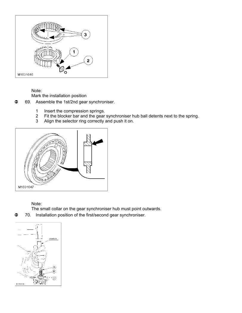
Note:Mark the installation position
µ 69. Assemble the 1st/2nd gear synchroniser.
1 Insert the compression springs.2 Fit the blocker bar and the gear synchroniser hub ball detents next to the spring.3 Align the selector ring correctly and push it on.
Note:The small collar on the gear synchroniser hub must point outwards.
µ 70. Installation position of the first/second gear synchroniser.

Note:Installation position (see previous step)
µ 71. Assemble the 1st/2nd gear synchroniser.
1 Install the gear synchroniser assembly.2 Fit a new circlip.
Note:See previous step.
µ 72. Assemble first gear wheel with double synchroniser.
1 Outer synchroniser ring2 Synchroniser cone3 Inner synchroniser ring4 1st gear wheel5 Needle roller bearing
CAUTION:The output pinion can only be placed on the splines in one position.
µ 73. Press on the output pinion.
1 Press on the output pinion using a suitable tube and press.2 Fit a new circlip.
Fit the output pinion with the mark facing upwards.

µ 74. Press on the taper roller bearing.
Press on the taper roller bearing using a suitable tube and press.
Layout of the output shaft
⁄ƒƒƒƒƒƒƒƒƒƒƒƒƒƒƒ¬ƒƒƒƒƒƒƒƒƒƒƒƒƒƒƒƒƒƒƒƒƒƒƒƒƒƒƒƒƒƒƒƒƒƒƒƒƒƒƒƒƒƒƒƒƒƒƒƒƒƒƒƒƒƒƒƒƒƒƒƒƒƒƒƒƒƒƒø
≥ Item ≥ Description ≥
√ƒƒƒƒƒƒƒƒƒƒƒƒƒƒƒ≈ƒƒƒƒƒƒƒƒƒƒƒƒƒƒƒƒƒƒƒƒƒƒƒƒƒƒƒƒƒƒƒƒƒƒƒƒƒƒƒƒƒƒƒƒƒƒƒƒƒƒƒƒƒƒƒƒƒƒƒƒƒƒƒƒƒƒƒ¥
≥ 1 ≥ 3rd gear wheel ≥
√ƒƒƒƒƒƒƒƒƒƒƒƒƒƒƒ≈ƒƒƒƒƒƒƒƒƒƒƒƒƒƒƒƒƒƒƒƒƒƒƒƒƒƒƒƒƒƒƒƒƒƒƒƒƒƒƒƒƒƒƒƒƒƒƒƒƒƒƒƒƒƒƒƒƒƒƒƒƒƒƒƒƒƒƒ¥
≥ 2 ≥ 3rd gear wheel ≥
√ƒƒƒƒƒƒƒƒƒƒƒƒƒƒƒ≈ƒƒƒƒƒƒƒƒƒƒƒƒƒƒƒƒƒƒƒƒƒƒƒƒƒƒƒƒƒƒƒƒƒƒƒƒƒƒƒƒƒƒƒƒƒƒƒƒƒƒƒƒƒƒƒƒƒƒƒƒƒƒƒƒƒƒƒ¥
≥ 3 ≥ 5th gear wheel ≥
√ƒƒƒƒƒƒƒƒƒƒƒƒƒƒƒ≈ƒƒƒƒƒƒƒƒƒƒƒƒƒƒƒƒƒƒƒƒƒƒƒƒƒƒƒƒƒƒƒƒƒƒƒƒƒƒƒƒƒƒƒƒƒƒƒƒƒƒƒƒƒƒƒƒƒƒƒƒƒƒƒƒƒƒƒ¥
≥ 4 ≥ 5th gear wheel ≥

√ƒƒƒƒƒƒƒƒƒƒƒƒƒƒƒ≈ƒƒƒƒƒƒƒƒƒƒƒƒƒƒƒƒƒƒƒƒƒƒƒƒƒƒƒƒƒƒƒƒƒƒƒƒƒƒƒƒƒƒƒƒƒƒƒƒƒƒƒƒƒƒƒƒƒƒƒƒƒƒƒƒƒƒƒ¥
≥ 5 ≥ 5th gear synchroniser ring ≥
√ƒƒƒƒƒƒƒƒƒƒƒƒƒƒƒ≈ƒƒƒƒƒƒƒƒƒƒƒƒƒƒƒƒƒƒƒƒƒƒƒƒƒƒƒƒƒƒƒƒƒƒƒƒƒƒƒƒƒƒƒƒƒƒƒƒƒƒƒƒƒƒƒƒƒƒƒƒƒƒƒƒƒƒƒ¥
≥ 6 ≥ Gear synchroniser, complete - (fifth/reverse gear) ≥
√ƒƒƒƒƒƒƒƒƒƒƒƒƒƒƒ≈ƒƒƒƒƒƒƒƒƒƒƒƒƒƒƒƒƒƒƒƒƒƒƒƒƒƒƒƒƒƒƒƒƒƒƒƒƒƒƒƒƒƒƒƒƒƒƒƒƒƒƒƒƒƒƒƒƒƒƒƒƒƒƒƒƒƒƒ¥
≥ 7 ≥ Circlip ≥
√ƒƒƒƒƒƒƒƒƒƒƒƒƒƒƒ≈ƒƒƒƒƒƒƒƒƒƒƒƒƒƒƒƒƒƒƒƒƒƒƒƒƒƒƒƒƒƒƒƒƒƒƒƒƒƒƒƒƒƒƒƒƒƒƒƒƒƒƒƒƒƒƒƒƒƒƒƒƒƒƒƒƒƒƒ¥
≥ 8 ≥ Synchroniser ring - reverse gear ≥
√ƒƒƒƒƒƒƒƒƒƒƒƒƒƒƒ≈ƒƒƒƒƒƒƒƒƒƒƒƒƒƒƒƒƒƒƒƒƒƒƒƒƒƒƒƒƒƒƒƒƒƒƒƒƒƒƒƒƒƒƒƒƒƒƒƒƒƒƒƒƒƒƒƒƒƒƒƒƒƒƒƒƒƒƒ¥
≥ 9 ≥ Needle roller bearing - reverse gear ≥
√ƒƒƒƒƒƒƒƒƒƒƒƒƒƒƒ≈ƒƒƒƒƒƒƒƒƒƒƒƒƒƒƒƒƒƒƒƒƒƒƒƒƒƒƒƒƒƒƒƒƒƒƒƒƒƒƒƒƒƒƒƒƒƒƒƒƒƒƒƒƒƒƒƒƒƒƒƒƒƒƒƒƒƒƒ¥
≥ 10 ≥ Reverse gearwheel ≥
√ƒƒƒƒƒƒƒƒƒƒƒƒƒƒƒ≈ƒƒƒƒƒƒƒƒƒƒƒƒƒƒƒƒƒƒƒƒƒƒƒƒƒƒƒƒƒƒƒƒƒƒƒƒƒƒƒƒƒƒƒƒƒƒƒƒƒƒƒƒƒƒƒƒƒƒƒƒƒƒƒƒƒƒƒ¥
≥ 11 ≥ Taper roller bearing ≥
¿ƒƒƒƒƒƒƒƒƒƒƒƒƒƒƒ¡ƒƒƒƒƒƒƒƒƒƒƒƒƒƒƒƒƒƒƒƒƒƒƒƒƒƒƒƒƒƒƒƒƒƒƒƒƒƒƒƒƒƒƒƒƒƒƒƒƒƒƒƒƒƒƒƒƒƒƒƒƒƒƒƒƒƒƒŸ
µ 75. Fit the fifth gear wheel together with the synchroniser ring and needle roller bearing.
1 Needle roller bearing2 5th gear wheel3 Synchroniser ring
Note:Mark the installation position
µ 76. Assemble the fifth/reverse gear synchroniser.
1 Insert the compression springs.2 Fit the blocker bar and the detent balls next to the spring.3 Align the selector ring correctly and push it on.

Note:Install the gear synchroniser hub with the small collar and the ring groove pointing outwards.
µ 77. Installation position of gear synchroniser.
Note:Install the gear synchroniser hub with the small collar and the ring groove pointing outwards.
µ 78. Fit the fifth/reverse gear synchroniser.
1 Install the gear synchroniser assembly.2 Attach a new circlip.
µ 79. Assemble the reverse gear wheel.

1 Synchroniser ring2 Needle roller bearing3 Reverse gearwheel
µ 80. Press on the taper roller bearing.
Press on the taper roller bearing using a suitable tube and press.
Measure the shims.
Note:Do not lubricate taper roller bearings that are to be re-used. Fit new taper roller bearings untreated.
µ 81. Insert the input and output shafts into the transmission housing.
Engage 4th gear.Put the input and output shafts together and insert them in the transmission housing.

Note:Do not lubricate taper roller bearings that are to be re-used. Fit new taper roller bearings untreated.
µ 82. Install the differential.
Note:The mating face must be scrupulously clean.
µ 83. Fit the housing sections on the clutch side.
Fit the special tool and the longer bolt.
µ 84. Assemble the transmission housing sections on the clutch side.
Tighten the 16 flange bolts evenly.

µ 85. Attach the special tool.
Fit the measuring bar to the 4th gear wheel.
µ 86. Prepare the input shaft for measurement.
Turn the input shaft back and forth about 20 times so that the bearings settle.
µ 87. Fit the dial gauge.
1 Fit a steel mounting plate (eg 21-146) to the transmission.2 Install the magnetic fixture.3 Set the dial pointer to ”0".

µ 88. Measure the input shaft end float.
Note:Carry out the measurement preparations and the measurement three times and calculate the average value.1 Raise the input shaft using the lever.2 Make a note of the result (eg 0,22 mm).For example: 0,22 mm + 0,23 mm + 0,21 mm divided by three = 0,22 mm.
µ 89. Prepare the output shaft for measurement.
Turn the input shaft back and forth about 20 times so that the bearings settle.
µ 90. Prepare the output shaft for measurement.

Fit the dial gauge.Set the dial gauge to ”0".
µ 91. Measure the output shaft end float.
Note:Carry out the measurement preparations and the measurement three times and calculate the average value.
Raise the output shaft using the lever and make a note of the result, eg, 0,32 mm.For example: 0,32 mm + 0,34 mm + 0,33 mm divided by three = 0,33 mm.
µ 92. Prepare the differential for measurement.
Turn the input shaft approx. 20 times back and forth and press down the differential at the same time.
Fit the dial gauge and set it to ”0".

Note:Carry out the measurement preparations and the measurement three times and calculate the average
value.µ 93. Measure the differential end float.
Lift up the differential using the special tool and make a note of the result, eg 0,34 mmFor example: 0,34 mm + 0,36 mm + 0,37 mm divided by three = 0,36 mm.
Measure the shim thickness to be inserted (mm dimensions)
⁄ƒƒƒƒƒƒƒƒƒƒƒƒƒƒƒƒƒƒƒƒƒƒƒƒƒƒƒƒƒƒƒƒƒƒƒƒƒƒƒƒƒƒ¬ƒƒƒƒƒƒƒƒƒƒƒƒƒƒƒƒƒƒƒƒƒƒ¬ƒƒƒƒƒƒƒƒƒƒƒƒƒƒƒƒƒƒƒƒƒƒ¬ƒƒƒƒƒƒƒƒƒƒƒƒƒƒƒƒƒƒƒƒƒƒ
≥ Description ≥ Input Shaft ≥ Output shaft ≥ Differential
√ƒƒƒƒƒƒƒƒƒƒƒƒƒƒƒƒƒƒƒƒƒƒƒƒƒƒƒƒƒƒƒƒƒƒƒƒƒƒƒƒƒƒ≈ƒƒƒƒƒƒƒƒƒƒƒƒƒƒƒƒƒƒƒƒƒƒ≈ƒƒƒƒƒƒƒƒƒƒƒƒƒƒƒƒƒƒƒƒƒƒ≈ƒƒƒƒƒƒƒƒƒƒƒƒƒƒƒƒƒƒƒƒƒƒ
≥ Measuring shim in mm ≥ 1,00 ≥ 1,00 ≥ 1,10
√ƒƒƒƒƒƒƒƒƒƒƒƒƒƒƒƒƒƒƒƒƒƒƒƒƒƒƒƒƒƒƒƒƒƒƒƒƒƒƒƒƒƒ≈ƒƒƒƒƒƒƒƒƒƒƒƒƒƒƒƒƒƒƒƒƒƒ≈ƒƒƒƒƒƒƒƒƒƒƒƒƒƒƒƒƒƒƒƒƒƒ≈ƒƒƒƒƒƒƒƒƒƒƒƒƒƒƒƒƒƒƒƒƒƒ
≥ Measured end float (mm) ≥ + 0,22 ≥ + 0,33 ≥ + 0,36
√ƒƒƒƒƒƒƒƒƒƒƒƒƒƒƒƒƒƒƒƒƒƒƒƒƒƒƒƒƒƒƒƒƒƒƒƒƒƒƒƒƒƒ≈ƒƒƒƒƒƒƒƒƒƒƒƒƒƒƒƒƒƒƒƒƒƒ≈ƒƒƒƒƒƒƒƒƒƒƒƒƒƒƒƒƒƒƒƒƒƒ≈ƒƒƒƒƒƒƒƒƒƒƒƒƒƒƒƒƒƒƒƒƒƒ
≥ Dimension for pre-tension (mm) ≥ - ≥ + 0,13 ≥ + 0,33
√ƒƒƒƒƒƒƒƒƒƒƒƒƒƒƒƒƒƒƒƒƒƒƒƒƒƒƒƒƒƒƒƒƒƒƒƒƒƒƒƒƒƒ≈ƒƒƒƒƒƒƒƒƒƒƒƒƒƒƒƒƒƒƒƒƒƒ≈ƒƒƒƒƒƒƒƒƒƒƒƒƒƒƒƒƒƒƒƒƒƒ≈ƒƒƒƒƒƒƒƒƒƒƒƒƒƒƒƒƒƒƒƒƒƒ
≥ End float (mm) ≥ - 0,05 ≥ - ≥ -
√ƒƒƒƒƒƒƒƒƒƒƒƒƒƒƒƒƒƒƒƒƒƒƒƒƒƒƒƒƒƒƒƒƒƒƒƒƒƒƒƒƒƒ≈ƒƒƒƒƒƒƒƒƒƒƒƒƒƒƒƒƒƒƒƒƒƒ≈ƒƒƒƒƒƒƒƒƒƒƒƒƒƒƒƒƒƒƒƒƒƒ≈ƒƒƒƒƒƒƒƒƒƒƒƒƒƒƒƒƒƒƒƒƒƒ
≥ Required thickness of shim ≥ = 1,17 ≥ = 1,46 ≥ = 1,79
√ƒƒƒƒƒƒƒƒƒƒƒƒƒƒƒƒƒƒƒƒƒƒƒƒƒƒƒƒƒƒƒƒƒƒƒƒƒƒƒƒƒƒ≈ƒƒƒƒƒƒƒƒƒƒƒƒƒƒƒƒƒƒƒƒƒƒ≈ƒƒƒƒƒƒƒƒƒƒƒƒƒƒƒƒƒƒƒƒƒƒ≈ƒƒƒƒƒƒƒƒƒƒƒƒƒƒƒƒƒƒƒƒƒƒ
≥ Adjustment shim availability (mm) ≥ 1,15 - 1,71 (in 0,01 ≥ 1,31 - 1,91 (in 0,02 ≥ 1,40 - 2,20 (in 0,05
≥ ≥ mm steps) ≥ mm steps) ≥ mm steps)
¿ƒƒƒƒƒƒƒƒƒƒƒƒƒƒƒƒƒƒƒƒƒƒƒƒƒƒƒƒƒƒƒƒƒƒƒƒƒƒƒƒƒƒ¡ƒƒƒƒƒƒƒƒƒƒƒƒƒƒƒƒƒƒƒƒƒƒ¡ƒƒƒƒƒƒƒƒƒƒƒƒƒƒƒƒƒƒƒƒƒƒ¡ƒƒƒƒƒƒƒƒƒƒƒƒƒƒƒƒƒƒƒƒƒƒ
Note:Fit the special tool in the transmission recesses.

µ 94. Remove the adjustment shim and the bearing rings.
From the input shaftFrom the differential
Note:Fit the special tool in the transmission recesses.
µ 95. Remove the input shaft bearing ring and the shim.
µ 96. Insert the shims and the bearing rings into the housing section on the clutch side.
Warm the housing locally to about 80 degrees Centigrade.Cool the bearing rings with refrigerant spray.
1 Insert the shims of the required thickness.2 Insert the bearing rings.
CAUTION:The pressure applied must not exceed 15 kN.
Note:Install using the press, do not drive it in.Bearing rings from the:Input shaft using 14-010Output shaft using 15-036Differential using 14-024

µ 97. Install the shims and the bearing rings.
1 Install the shims of the required thickness.2 Bearing rings for the:Install the input shaft, output shaft and differential as described in the steps.
Note:Lubricate the taper roller bearings.
µ 98. Install the input and output shafts together.
Swivel the input shaft to one side and insert the reverse gear idler (for order of installation, see the following step).
µ 99. Order of installation for the reverse gear idler.

1 Lower thrust washer.2 Needle roller bearing3 Reverse gear idler.4 Upper thrust washer5 Circlip
µ 100. Fit the selector fork.
Put the 4th gear selector ring in neutral.Insert the fifth/reverse gear selector fork and swivel to one side.
µ 101. Install the 3rd/4th gear selector fork.
Swivel the fifth/reverse gear selector fork back into position.

Note:When correctly positioned all the selector rods are at the same height.
µ 102. Install the 1st/2nd gear selector fork and rods.
µ 103. Install the differential.
1 Install the differential.2 Install the clean magnetic disc in the slot provided.
Fit the selector shaft oil seal.
Note:The selector shaft must be clean and free of burrs.
µ 104. Fit the selector shaft oil seal.
Push the selector shaft inwards.1 Push the oil seal and the assembly sleeve onto the selector shaft.2 Drive in the oil seal just up to the stop.

µ 105. Remove the assembly sleeve, fit the dust cover.
Note:The mating face must be dry. Apply sealer (WSK-M2G348-A5) evenly on the inside of the sealing
surface. (The sealant bead should have a constant diameter of about 2 mm.)µ 106. Apply sealer to the mating face.
µ 107. Fit the transmission housing sections on the clutch side.
Note:The transmission housing must not, under any circumstances, be turned when tightening the bolts.
Tighten the 16 flange bolts within 15 minutes, working diagonally.

Note:Put the gearshift mechanism in neutral.
µ 108. Fit the selector mechanism.
Apply sealer evenly to the outer side of the mating face.Fit the selector mechanism and tighten.
Note:If the turning torque is too high, all the measurements must be repeated (including the measurement
to determine the required shim thickness).µ 109. Measure the turning torque.
Engage 4th gear.Measure the turning torque.

µ 110. Fit the speedometer worm drive.
1 Install the drive pinion.2 Drive in the notched pin using a hammer.
Fit the differential oil seal.
µ 111. Fit the differential oil seals.
µ 112. Install the guide sleeve.
Fit the guide sleeve with a new O-ring and apply sealer (WSK-U26348-A5).

µ 113. Install the release shaft.
Coat the bearing points on the release shaft with high-melting point grease.
µ 114. Fit the thrust bearing.
Coat the guide sleeve and clutch teeth thinly with high-melting point grease.
µ 115. Remove the special tools.

µ 116. Fit the clutch release lever.
1 Fit the bearing bush and the protective cap.2 Fit the clutch release lever and tighten the bolts.