mu0011 installation instruction
TRANSCRIPT

60LBS27KG
Max: Max:400x400mm/16x16"Min:75x75mm/3x3"
26"~55"
(A1)
If you have any questions, please contact us via [email protected]
MU0011 INSTALLATION INSTRUCTION
- 1 -
Velcro cable ties X5 Bubble level X1 HDMI cable X1
v3

- 2 -
Hammer3/8"(10mm)
Masonry Drill Bit7/32"(5.5mm)Wood Drill BitAwlStud Finder
Socket Wrench1/2"(13mm)ElectrodrillScrewdriverPencil
3 What is your wallmade of?
Solid concretewall?
● This product is designed for use in wood stud or solid concrete wall. - DO NOT install into drywall alone.● The wall must be capable of supporting five times the weight of the TV and mount combined.● Do not apply this product to any purpose not indicated by MOUNTUP.● Incorrect installation may result in product damage or body injury. MOUNTUP shall bear no responsibility for any damage or injury resulted from incorrect installation, incorrect assembly or misuse.
Please read this instruction carefully before installation.If you do not understand these instructions or have doubts about the safety of theinstallation, assembly or use of this product, contact Customer Service [email protected]
5 Safety Caution
2M2M
Band Tape
Drywall withwood studs?
CAUTION:
Yes --- Perfect!
No --- This mount is NOT compatible.
MAX:400mm/16"
MAX:400mm/16"
Yes --- Perfect!
No --- This mount is NOT compatible.
4 Installation Tools(Not Included)
2 Does your TV(including accessories)weigh less than60 LBS (27 KG)?
1 Is your TV VESAequal to/greater than75x75mm /3x3" andequal to/less than400x400mm/16x16"?
Before getting started, let’s make sure this mount is perfect for you!
60LBS27KG
Max:
DO NOT installinto drywall alone
Perfect! Perfect!
Woo
d Stu
d Ins
tall
Conc
rete
Instal
l

Arm and Wall Plate
Hardware Included
01 x1
Brackets
02 x2
This product contains small items that could be a choking hazard if swallowed. Before starting assembly, verify all parts are included and undamaged. If any parts are missing or damaged, do not return the damaged item to your dealer; please contact our customer service team. Never use damaged parts!
NOTE: Not all parts and hardware included will be used.
WARNING:
Philips ScrewsM6 x 15mmM6 x 30mm
Philips ScrewsM4 x 12mmM4 x 30mm
WashersØ6mmM4-5-6
Spacers
L10mm
x4x4 x4x4
Philips Screws M8 x 25mmM8 x 45mm
x4x4 x8 x4
Spacers L5mm
x8
TV Screws / Washers
M-A M-B M-C M-D M-E M-F
Hardware (Wall /Product)
5/16 x 2½ inLag Bolts
x3 x1 CA
WashersØ8mm
x3B
Open end wrench
- 3 -

STEP 1-1 Select TV Screw Diameter
Thread screws by hand into the threaded holes on the back of your TV to select which screw diameter fits your TV.
M6M4 M8
STEP 1-2 Select TV Screw Length
Correct CorrectToo LongToo Short
- 4 -

STEP 1-3 Attach the Bracket
Position your brackets over your TV hole pattern - making sure the brackets are centered and level over the TV hole pattern. Secure the brackets using your screw/washer/spacer selection:(a) for Flat Back(b) for Round Back / Extra space
CAUTION: Ensure bracket is securely fastened before moving on to the next step.
M-E
M-FM-D
M-A
(a) Flat Back
M-E
(b) Round Back / Extra Space
Not for M8 screws
Use the shorter screws
Not for M8 screws
- 5 -
M-BM-C
M-A
Use the longer screwsM-B
M-C

STEP 2A Wall Plate Installation (Wood stud)
2A-1
2A-2
Locate your studs. Verify and mark the center of the stud by finding the stud edges using an awl, a thin nail, or an edge-to-edge stud finder.
Position the wall plate at your desired height and line up the holes with your stud center line. Level the wall plate and make the holes x3.
01
2A-3
Drill pilot holes using a 7/32 in. (5.5 mm)diameter drill bit.
IMPORTANT: Pilot holes must be in. (70 mm). Be sure to drill into the center of the stud.
drilled to a depth of
7/32
in.
Ø5.
5 m
m
in. (70 mm)
- 6 -
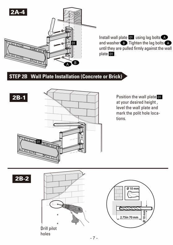
2A-4
01 AInstall wall plate using lag bolts and washer B . Tighten the lag bolts until they are pulled firmly against the wall plate .
01
01
A B
- 7 -
01Position the wall plate at your desired height , level the wall plate and mark the polit hole loca-tions.
01
Drill pilot holes
2B-2
2B-1
2.75in 70 mm
Ø 1
0 m
m
Ø 10 mm
STEP 2B Wall Plate Installation (Concrete or Brick)
AB
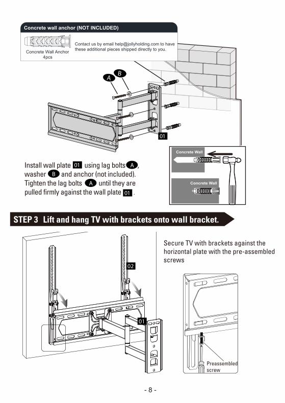
Secure TV with brackets against the horizontal plate with the pre-assembled screws
Preassembled screw
- 8 -
AB
Concrete Wall
Concrete Wall
STEP 3 Lift and hang TV with brackets onto wall bracket.
Contact us by email [email protected] to havethese additional pieces shipped directly to you.Concrete Wall Anchor
4pcs
Concrete wall anchor (NOT INCLUDED)
01 AB
01
Install wall plate using lag bolts , washer and anchor (not included). Tighten the lag bolts until they are pulled firmly against the wall plate .
A
01
02
01

Tilting angle adjustment (+5° / -10°)Pull TV to your desired angle then fasten tilting nuts withopen end wrench.
Leveling adjustment (-3°/+3°)If needed, TV can be leveled ±3 degrees via adjusting the 4 nuts with the open end wrench.
(Tilting)
(Leveling)
±3°
CC
- 9 -
Adjustments
± 3°
± 3°
C
C

Product dimensions:
-
5°
10°
-3°/+3°
498mm
230mm
MAX:400mmMIN:75mm
MAX:400mm
MIN:75mm
425mm
435mm
435mm
84mm
- 10 -