multi-element ultrasonic linear arrays for … · multi-element ultrasonic linear arrays for ......
TRANSCRIPT

MULTI-ELEMENT ULTRASONIC LINEAR ARRAYS FOR RAPID LAP-JOINT INSPECTION
Robert A Smith and Stephen J Willsher Defence Evaluation and Research Agency
Griffith Building - A7 DERA, Farnborough, GU14 0LX, UK
Telephone: +44 1252 395655 Telefax: +44 1252 397223
E-mail: [email protected]
ABSTRACT
Rapid detection and characterization of disbonding and corrosion in lap joints is a high priority for both military and civil transport aircraft operators. Approaches to this requirement have followed two clearly different routes: the development of novel large-area inspection systems, and the enhancement of current ultrasonic or eddy-current methods to reduce inspection times. This paper deals with the use of multi-element transducers to increase the scanning speed for ultrasonic lap-joint inspection. Array technology has been very widely used in the medical ultrasound field although rarely above 10 MHz, whereas lap-joint inspection requires a pulse center-frequency of 12 to 20 MHz in order to resolve the separate interfaces in the lap joint. A specification for a 128 mm-long multi-element linear array of 4 mm x 2 mm ultrasonic elements for use with the ANDSCAN® scanning software was sent to selected NDT manufacturers with experience in the medical imaging field. This paper analyses the performance of the transducer that was produced and evaluates its use in scanning systems of different configurations. Preliminary trials have produced scanning speeds along the lap-joint in excess of 0.18 m/min (or 7" per minute) - limited by the data acquisition card in the computer. After upgrading this card, a speed of up to 3.6 m/min (11'8" per minute) should be possible with a flaw detector capable of a pulse-repetition-frequency (PRF) of 8 kHz, although this may then be limited by the time taken to update the C-scan information in the computer.
1. INTRODUCTION
The requirement for rapidly detecting corrosion and disbonds in lap joints of transport aircraft has prompted the development of various new NDT methods and large-area imaging systems. However, there is still great potential for speeding up conventional methods, such as eddy-currents and ultrasonics, using automated or semi-automated scanners. Currently there are several systems available that scan either a single transducer in a raster scan, or several single-element transducers simultaneously (1-3). Another method for increasing scanning speed even further is to electronically scan through a linear array of transducer elements and manually move this array along the lap joint. Thus DERA is developing both ultrasonic and eddy-current arrays and evaluating their inspection performance and the potential speed of inspection.
A considerable amount of research and development on linear-array transducers has been completed in the past for the medical-ultrasound industry where such devices have been commonplace for at least 20 years. However, they have been noticeably absent from the in-service NDT world during that period. Recent years have seen the development of piezo-composite transducers which, by their very nature, are highly suitable for use as arrays and there have been several moves to introduce these arrays into NDT (4-5). In addition, piezo-composite arrays can be flexible (6-8) and this could prove essential because the most obvious problem with using array technology on in-service structures is that of maintaining coupling (for ultrasonics) or stand-off (for eddy-currents) on uneven surfaces. Thus a substantial part of DERA’s

development program will be looking at this problem. This paper concentrates on the development of an ultrasonic array with a sufficiently high frequency range for lap-joint inspection, and a rapid scanning system to plot the C-scan results.
2. LINEAR-ARRAY TRANSDUCER
The prototype array transducer which was designed and manufactured to a DERA specification by Diagnostic Sonar Ltd (DSL) from Livingston, Scotland, can be seen in Figure 1 mounted in a simple trolley. The array had to interface to a conventional flaw detector and operate at a center frequency of over 12 MHz in order to resolve the front and back of the various aluminum lap-joint skins, and preferably even the front and back of the bond. Each scan-line was required to have an entry beamwidth of between 2 mm and 4 mm.
Figure 1. Lap-joint array developed by Diagnostic Sonar Ltd to DERA's specification (9). The prototype
carriage is designed to keep the ultrasound beams normal to the surface.
The array has been described previously (9), and uses a poly-vinylidene fluoride (PVDF) piezoelectric sheet sandwiched between a backing block and the stand-off material. For this lap-joint application an aluminum stand-off was chosen by DSL although other materials will also be investigated at DERA. A water stand-off is likely to give the cleanest ultrasonic signals but this will require a recirculating system with quite a high flow rate. The array comprises 64 electroded elements of size 4 mm x 2 mm (or 0.16" x 0.08"), spaced at 2 mm (0.08") centers, fired in pairs (see Figure 2). After each firing either the transmitting pair or the receiving pair are alternately incremented along by 2 mm (0.08"). Thus the result is 128 scan-lines spaced at 1 mm (0.04") centers.
The ultrasonic performance of the linear array has been initially assessed and the center frequency of approximately 12 MHz is sufficiently high to enable bond inspection and depth scans of corrosion sites.

However, at present the bandwidth is not as wide as is desirable for these inspections and this aspect is being addressed.
Figure 2. Schematic diagram of scan-line firing sequence for linear-array probe with 64 elements.
The multiplexer electronics, contained in the array itself, allows three modes of operation:
• single element with operator selection of the element,
• continuous cycling triggered by the flaw detector’s firing pulse, or
• computer control of the firing element.
The ANDSCAN software allows use of all of these modes and the last two are being assessed to decide which gives the optimum performance. Both have their advantages: cycling triggered from the flaw detector gives the fastest scanning speed but computer control avoids any loss of data points due to the asynchronous acquisition rates.
In the normal scanning configuration the array probe is connected to the flaw detector which is set to dual-transducer mode. There are additional connections to the computer for transmitting digital scan-line information, and to a power supply (see Figure 3).
In addition, the array can be used as a high-resolution paintbrush-type probe with just a flaw detector and no scanning system or computer. The sensitivity to small defects is greatly increased over a single-element paintbrush probe and the scan rate would be equivalent to that of a 4 mm x 128 mm paintbrush probe.

Figure 3. Schematic diagram of the operating configuration which includes a controlling computer, if required, which can also be used for the C-scanning software.
3. THE SCANNING SYSTEM
There are two different situations for rapid lap-joint inspection: long lengths of narrow lap splices and wider areas of doubler reinforcement. Hence it is important to provide suitable scanning systems for both of these instances. However, by far the most common application for rapid inspection on aging aircraft is the great lengths of narrow lap joints on large transport aircraft.
A method was required to track the linear position of the array as it moves along a lap joint which could be over 10 m long. This tracking system needed to be interfaced to C-scanning software and the DERA-developed ANDSCAN® system was the obvious choice (10,11). A modification to the standard R-theta scanning arm used a sprung extension potentiometer to measure the radial distance (see Figure 4). This enabled the standard software package to be used after a previous modification for use with multi-element arrays (12).
A trolley is used to hold the array perpendicular to the surface whilst allowing it to move up and down with spring pressure downwards. The array can also swivel about an axis parallel to the extension string. The use of a wheeled trolley also helps to maintain movement in a straight line although deviations will be correctly mapped because the scanning arm is still sensitive to angle as well as radial distance.

Figure 4. An ANDSCAN® positioning system fitted with a sprung extension potentiometer measures the distance along the lap joint.
Provided angular movement does not become rapid or oscillatory the measurement of angular position allows re-scanning of an area without the need to accurately re-position the trolley. However, it is important that the direction of movement is always towards or away from the ANDSCAN base unit because the software assumes that the array lies perpendicular to the extension string.
Another scanning method that is appropriate for a large area - wider than 128 mm - is a manual X-Y scanner. This is another option for interfacing with the ANDSCAN software (see Figure 5). In this case the scanner has been developed at DERA as a combination of two radial arms from the well-known R-Theta scanner originally produced for ANDSCAN. This configuration has advantages for wider areas because the array is always orientated the same way for each swathe. In contrast, the R-Theta scanner requires the array to be perpendicular to the radial direction and is less appropriate for multiple swathes across a large area.

Figure 5. An X-Y scanner for ANDSCAN with a smaller linear array attached, showing that orientation of the array is maintained.
4. RESULTS
A rapid inspection method is primarily concerned with defect detection rather than characterization, although if the same equipment can achieve both then this is very advantageous. Thus the important performance criteria for such a method are: in-plane spatial resolution to ensure critical defect sizes are detected, out-of-plane spatial resolution (equivalent to temporal resolution) to give adequate distinction between closely-spaced interfaces, and other frequency characteristics such as the center-frequency and bandwidth which would be important for spectroscopic measurements such as roughness measurement.
Defect detection capabilities are partly dependent on in-plane spatial resolution so a test block containing different sized flat-bottomed holes and slots was used (see Figure 6). The aim of the specification for the linear array was to achieve a 2 mm (0.08") resolution and the amplitude C-scan of the above test block in Figure 7 demonstrates the ability to detect 1.5 mm-wide (0.06") slots and resolve 1.5 mm-diameter (0.06") holes spaced at 2.5 mm (0.10") centers. However, the time-of-flight scan (or depth scan) in Figure 7 does not show the 1.5 mm (0.06") diameter holes. This was because the amplitude of the reflections from these smallest holes was insufficient to cross the gate threshold set on the flaw detector.
Preliminary trials have produced scanning speeds along the lap-joint in excess of 0.18 m/min (or 7" per minute) - limited by the data acquisition card in the computer. This was measured with a spot size (and therefore resolution) of 1 mm (0.04") and a 128 mm-wide (5") swathe. However, acquisition cards are now available with much improved acquisition features which are ideal for this particular application. After upgrading the data acquisition card, maximum scanning speeds should dramatically increase. Linear speeds up to 3.6 m/min (11'8" per minute) should be possible with a flaw detector capable of a pulse-

repetition-frequency (PRF) of 8 kHz, although this may then be limited by the time taken to update the C-scan information in the computer.
Figure 6. Diagram of resolution test specimen with flat-bottom holes and slots in 9 mm (0.36") thick
aluminum. The labels give the slot width, or hole diameter, in mm. The closest 1.5 mm (0.06") diameter holes are spaced at 2.5 mm (0.10") centers.
CONCLUSIONS
A new rapid lap-joint inspection has been developed using simple additions to conventional equipment. Ultrasonic resolution of 1.5 mm (0.06") and scanning resolution of 1 mm (0.04") at a speed in excess of 0.18 m/min (or 7" per minute) has been demonstrated - limited by the data acquisition card in the computer. This was measured with a spot size (and therefore scan step-size) of 1 mm (0.04") and a 128 mm-wide (5") swathe. After upgrading the data acquisition card, a speed of up to 3.6 m/min (11'8" per minute) should be possible with a flaw detector capable of a pulse-repetition-frequency (PRF) of 8 kHz Further work is required to optimize the ultrasonic performance the coupling onto curved or undulating surfaces, and the scanning speed.
ACKNOWLEDGMENTS
The authors are grateful to Mr Lyn Jones and Dr David Bruce of the NDE Group at DERA for assistance in the development of the linear array transducer and the scanning system, and to Mr David Lines of Diagnostic Sonar Ltd for the multiplexer design and transducer development.
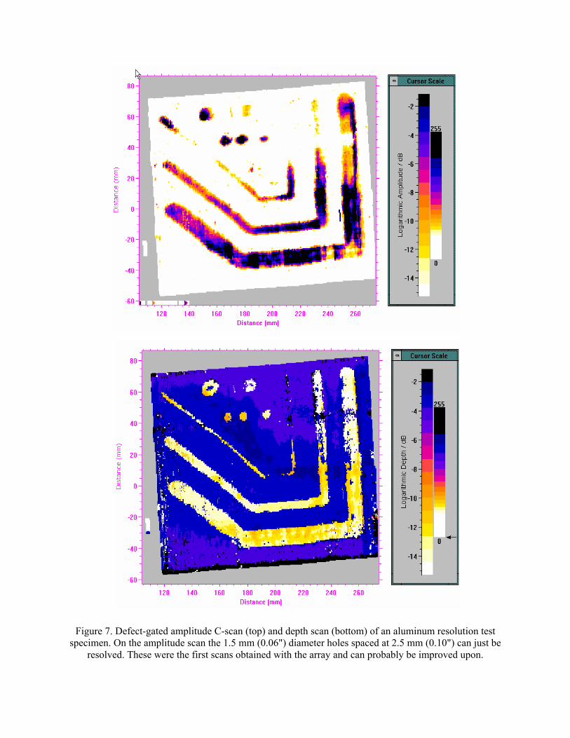
Figure 7. Defect-gated amplitude C-scan (top) and depth scan (bottom) of an aluminum resolution test specimen. On the amplitude scan the 1.5 mm (0.06") diameter holes spaced at 2.5 mm (0.10") can just be
resolved. These were the first scans obtained with the array and can probably be improved upon.

REFERENCES
1. Reighard M K, Van Oordt T W and Wood N L, “Rapid ultrasonic scanning of aircraft structures.” Materials Evaluation, Vol 49, No 12, pp 1506-1514, 1991.
2. Khalid A, Chen S, Fan A, Satter T and Bridge B, “Development of a climbing robot for the deployment of NDT sensors in hazardous environments.” . Insight - Journal of the British Institute of NDT, Vol 36, No 12, pp 943-948, 1998.
3. Backes P G, Bar-Cohen Y and Joffe B, “The Multifunction Automated Crawling System (MACS).” Proc IEEE Int Conf on Robotics and Automation, Albuquerque NM, pp 335-340, April 1977.
4. Savakus H P, Klicker K A and Newham R E, “PZT-Epoxy piezoelectric transducers: a simplified fabrication process.” Mater Res Bull, Vol 16, pp 677-680, 1980.
5. Hayward G and Hossack J, “Unidimensional modelling of 1-3 composite transducers.” J Acoust Soc Am, Vol 88, pp 599-608, 1990.
6. Powell D J and Hayward G, “Flexible ultrasonic transducer arrays for nondestructive evaluation applications - Part I: The theoretical modelling approach.” IEEE Transactions on Ultrasonics, Ferroelectrics, and Frequency Control, Vol UFFC-43, No 3, pp 385-392, 1996.
7. Powell D J and Hayward G, “Flexible ultrasonic transducer arrays for nondestructive evaluation applications - Part II: Performance assessment of different array configurations.” IEEE Transactions on Ultrasonics, Ferroelectrics, and Frequency Control, Vol UFFC-43, No 3, pp 393-402, 1996.
8. Reynolds P and Hayward G, “Design and construction of a new generation of flexible ultrasonic transducer arrays.” Insight - Journal of the British Institute of NDT, Vol 40, No 2, pp 101-106, 1998.
9. Lines D A, “Rapid inspection using integrated ultrasonic arrays”, Insight - Journal of the British Institute of NDT, Vol 40, No 8, pp 573-577, 1998.
10. Smith R A, “Evaluation and accuracy assessment of ANDSCAN - a non-destructive portable scanner, Part 1. ANDSCAN hardware and software,” Insight - Journal of the British Institute of NDT, Vol 37, No 4, pp 284-289, 1995.
11. Smith R A,“Evaluation and accuracy assessment of ANDSCAN - a non-destructive portable scanner, Part 2. NDT applications and specialised features; accuracy and repeatability,” Insight - Journal of the British Institute of NDT, Vol 37, No 5, pp 352-357, 1995.
12. Willsher S J and Smith R A, “Multi-element ultrasonic scanning of in-service air-frames”, Insight - Journal of the British Institute of NDT, Vol 40, No 3, pp 154-159, 1998.
OPTIMIZATION OF HIGH-FREQUENCY ARRAY TECHNOLOGY FOR LAP-JOINT INSPECTION
D.I.A. Lines, MA MSc MInstNDT - Chief Engineer, Diagnostic Sonar Ltd. K.R.Dickson, BSc MSc - Research Engineer, Diagnostic Sonar Ltd.
R.A. Smith, MA MSc CEng CPhys MInstP MInstNDT - DERA Fellow, DERA S.J. Willsher, BEng CEng MInstNDT - Senior Scientist, DERA
Abstract
Whilst the search for a truly large-area inspection system for lap-joint inspection continues, it is true to say that more conventional methods still have great potential for speed enhancements. Initial work on high-frequency ultrasonic arrays by DERA and Diagnostic Sonar has achieved inspection rates of several feet of lap-joint per minute. This method could detect disbonds of less than 0.1 inch across and corrosion depths of less than 0.002 inch in the outer skin. Conventional ultrasonics has the potential for rapid high-resolution scanning at up to 12 feet of lap joint per minute.
Several lessons were learned during this evaluation exercise, notably in terms of probe-handling and the practicalities of scanning with a large array. A better specification for the ultrasonic requirements was also developed. This paper reports the results of a further study of ultrasonic array-probe design in order to obtain a flexible coupling mechanism whilst retaining adequate signal-to-noise, uniformity across the array and ease of handling during lap-joint inspection. Relative benefits of planar and focused configurations have also been investigated, together with the implications for array element size and shape.
Introduction
Lap-joint inspection is becoming progressively more important as more aircraft are being operated beyond their original design life. Ultrasonic Non-Destructive Evaluation (NDE) techniques have been shown to be useful in corrosion monitoring. Thickness gauging provides a means for detecting the loss of material and this can be combined with a position sensing system such as the ANDSCAN® to produce a C-scan map of the corroded area. a. A feature of aging aircraft is that the condition at the time of manufacture may not have been documented. Thickness gauging can not distinguish between thinning produced at manufacture or from subsequent corrosion. The Defence Evaluation and Research Agency (DERA) has therefore developed a spectroscopic technique for measuring surface roughness of hidden surfaces. b. These ultrasonic techniques produce a measurement for the point just beneath the transducer and so need a 2-dimensional scan of the probe to map out an area. This is a slow process when the scanning is done manually and a variety of approaches have been tried to achieve a speed increase. Motorised scanning systems can translate the probe over the surface

faster but this high translation speed can produce its own problems with coupling and with surface roughness. Clusters of transducers allow data to be acquired from a number of locations in parallel but there are difficulties in getting the transducers to match beam positions and acoustic performance.
Arrays can be regarded as a special case of this multiple transducer configuration. Each element is part of the same monolithic structure and this greatly assists beam matching. Signals from a group of elements can be combined to produce a scan with overlapping beams as well as the possibility of focusing. Diagnostic Sonar Ltd (DSL) has developed a range of arrays with integrated multiplexers for increasing inspection speed. These can be used with existing equipment such as flaw detectors, c with real-time imaging systems, d and have been shown by DERA to offer significant scan speed improvements with manual mapping. e.
Some initial work on the extension of these array techniques to inspect lap-joints has been reported. f, g. These arrays had some limitations and so further work has been undertaken to address these problems. This paper reviews the advantages of the arrays, reports on the current state of these further developments and outlines the next steps to be taken.
Arrays for lap-joint inspection Lap-joint inspection requirements
The prime technique for inspection of lap-joints is thickness gauging. The transducers
have to be high frequency and wide bandwidth to produce the short duration pulses needed to achieve acceptable depth resolution for the thin aluminium alloy sheet of the lap-joint.
The ultrasonic spectroscopy technique developed by DERA, b for surface roughness measurement makes use of the preferential scattering of high frequencies. Measurement of the loss of these high-frequency components also requires a wide bandwidth transducer. Early single element probe investigations suggested that a focused acoustic field could offer improved tolerance to variations in angle of incidence. Any array implementation should therefore provide the capability for focused operation.
The width of the lap-joint requires a C-scan swathe of over 100mm and it is desirable to be able to inspect this in a single pass. The aim was to inspect on a 1mm pitch and to try to achieve a symmetrical acoustic beam profile in each direction. DSL’s piezo-polymer arrays, with integrated pulser-receivers and scanning electronics, are able to produce 128 overlapping beams on a 1 mm pitch and therefore were suitable for single pass operation. Focusing in the slice thickness direction can be achieved by curvature of the elements but this is fixed at manufacture. Electronic beamforming, by providing differential delays between the signals to and from adjacent elements, can be varied by altering the delays. However the constraint of matching the beam profiles in each direction means that a fixed electronic focus is satisfactory. Arrays - Stepped scanning and focusing Arrays are used in many fields as diverse as radar, seismology, oceanography and medical imaging. The common terminology between these fields, such as the term “phased array”, shows their common ancestry. However, these techniques have evolved in different ways in the separate fields and this can give rise to considerable confusion. It is therefore appropriate to clarify the scanning and focusing mechanisms in this particular application.

Arrays - Stepped scanning The array is made up of a number of elements, usually identical in size and arranged on a uniform pitch. A transmit multiplexer is used to connect the excitation signal to a group of these elements and this group is called the active transmit aperture. The acoustic signals from each element combine as they propagate through the medium and Huygens’ principle can be used to predict the acoustic field pattern at any point. If the element width is close to the element pitch then the field will be similar to that from an unfocused single element probe of the same size and location as the active transmit aperture. The same principle can be applied to the echoes which are received on a group of elements known as the active receive aperture. Figure 1a shows the case where the active transmit and receive apertures are coincident and produce an unfocused beam similar to that from a conventional transducer with dimensions equal to 3 elements. The scanning action is achieved by stepping the active transmit and receive apertures along the array. A scan of overlapping beams is produced if the step pitch is smaller than the beam width. Figure 1a. Stepped array Figure 1b. Stepped focused array
Muxer
Pulser Receiver
Planewavesin farfield
Focus
DelayProfile
Pulser Receiver Arrays - Focusing A conventional transducer can generate a focused acoustic beam by shaping of the piezo-electric material or by insertion of an acoustic lens in the sound path. In either case the effect is to make the acoustic path length, from the focus to every point on the transducer, the same value.
This same differential delay mechanism can be implemented by an electronic delay to the different elements which make up the active apertures and so can produce a focus, as shown in Figure 1b, where the position of the focus is dependent on the magnitude of the delays. The focus will be on axis if the delays are symmetric as shown, but they can be made asymmetric to steer (and focus) the beam off-axis.
Phased-array radar uses the same phase alignment techniques to steer the beam through a range of scan angles and the terminology has often been adopted for the ultrasound case. This is felt to be unhelpful since the array shown in Figure 1b scans the beam by stepping the aperture and the term stepped focused array is preferred here. Arrays for lap-joint inspection Arrays have almost completely dominated the medical ultrasound imaging market and this has contributed to a rapid drop in cost but they have made relatively little inroads into NDE. They

can be regarded as a distributed data collection system and so have an inherent speed advantage for area coverage, even if the data is being collected from just one site at a time. Maximum scan rates
A mechanically-scanned single element probe has a significant inertia and so data has to be collected “on the fly”. At high scan speeds, the probe will have moved between transmission and reception and this misalignment provides an upper limit to the scan rate even if there are no other mechanical constraints. Arrays have no such beam inertia and the transmit and receive apertures not only remain aligned during acquisition but can be changed to any other position along the array in a matter of microseconds.
The maximum scan rate of an array is determined by the highest acceptable Pulse Repetition Frequency (PRF) which in turn is affected by the acoustic characteristics of the target material. The data acquisition cannot finish until the echoes have returned from the furthest range of interest and this will be affected by the propagation time in the acoustic delay line. The next pulse cannot be sent until the echoes from any previous excitations are below the dynamic range of the display. A steered array uses the same acoustic aperture on each beam and so has to rely on the ability of the beamformer to reject signals from unwanted directions. The stepped array can benefit from the fact that the next beam can be far from the previous locations, and the image frame can be built up from a number of interleaved image fields (like a television picture). Higher PRFs can be reached without echoes from previous transmissions producing display artefacts. This ability of arrays to produce a high image frame rate means that they are suitable for interactive imaging - a feature that has been found to be vital in the medical field.
The ultimate in inspection speed is achieved when multiple beams are produced in parallel. One option is to transmit a relatively broad beam and produce multiple receive beams from within it and DSL’s Flaw Imager system uses this approach to double the frame rate by generating 2 beams from each transmission. The technique can be taken to an extreme where the whole array is used as a transmitter and the data from each element is recorded in parallel and the beams are synthesized after reception is complete. However, this is expensive and loses the benefit of the transmitter beam to improve resolution even though the image frame rate is now the same as the PRF. If signal to noise ratio (SNR) permits, the signals can be recorded from all elements whilst each element is excited in turn. The data reconstruction allows for every point in the image to be in focus for both transmit and receive.
Area coverage
Arrays are also well-suited to area coverage because their precise beam pattern means they can be readily interfaced to commercially available C-scan mapping systems such as the ANDSCAN®. Even without the documentation advantages of a C-scan display, the overlapping beams and wide swathe mean that quick manual inspections can be performed with confidence that 100% inspection has been achieved.
Arrays have no moving parts and are therefore robust, small and light when compared to the mechanically driven alternatives and these are all important considerations for the end-user. Array disadvantages
Arrays have a number of disadvantages and some of these were encountered during the project. The prime reason for using arrays is their ability to inspect a line rather than a point and this means that the acoustic interface with the target is considerably larger than for a conventional transducer. Maintaining good contact over this large area is a major problem in practice. A

surface-conforming delay line would reduce this problem but even the best deformable materials have unacceptable high-frequency attenuation.
The high centre frequency is not a problem for small probes but the need to achieve this over a large array is a significant challenge, especially the task of reducing the variation in element-to-element properties (both in sensitivity and spectral matching). Initial design
The key features of DERA’s original design specification included: an array length of around 128mm; a beam width of 2 to 4mm at entry into aluminium but the actual value should be matched to within 30% in orthogonal directions; a beam pitch of 1mm; a target temporal pulse length of less than 100ns; uniformity of sensitivity, damping etc. between elements so that no operator adjustment is needed; acoustic interface to standard flaw detector; beam number interface to ANDSCAN® system.
Implementation
The only approach in the time available was based on DSL’s integrated array system, developed for area inspection but at lower frequencies (2MHz - 8MHz). This used piezo-polymer film as the active component of a 64 element 128mm long array. The low-capacitance of this material requires localised pulser-receivers for each element and these had been integrated, along with multiplexers and control circuitry, into the modular assembly seen in Figure 2. Figure 2. Structure of array.
Pulser-receiversand multiplexersBeamformersand interfacingelectronics
Transducer andbacking block
Acoustic Delay line
The specification required the beam position to increment automatically at each flaw detector transmission while the ANDSCAN® monitored the beam counter to allow correct placement in the display. The controller had been designed to interface the array to a wide range of equipment, from conventional flaw detectors to real-time imaging systems, and so already had the necessary beam counters. In practice, it was found that scan speed was optimised by using the computer to output the desired beam number to the array head, as normally used for B-scanning. The controller is able to define the size and position of the active transmit and receive apertures independently and this allows 128 beams from 64 elements even for an unfocused stepped array.
Some plastics, such as cross-linked polystyrene, have acoustic properties which are suitable for acoustic delay lines and are therefore widely used with conventional transducers. The
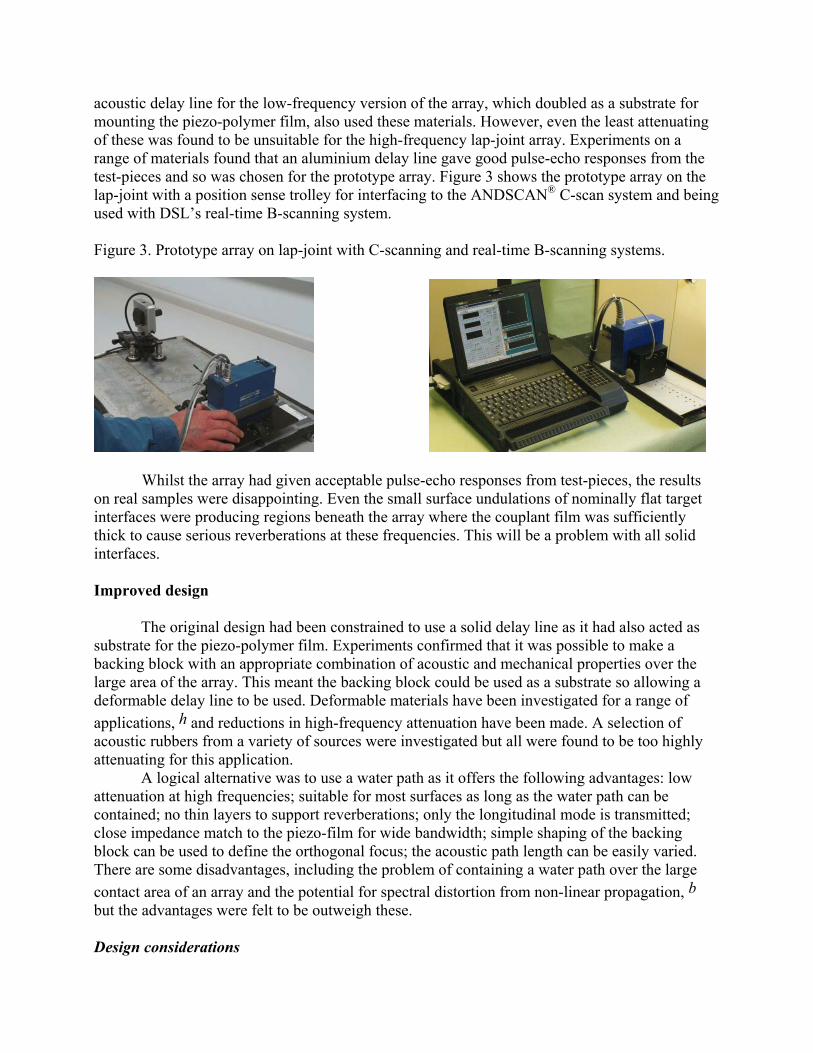
acoustic delay line for the low-frequency version of the array, which doubled as a substrate for mounting the piezo-polymer film, also used these materials. However, even the least attenuating of these was found to be unsuitable for the high-frequency lap-joint array. Experiments on a range of materials found that an aluminium delay line gave good pulse-echo responses from the test-pieces and so was chosen for the prototype array. Figure 3 shows the prototype array on the lap-joint with a position sense trolley for interfacing to the ANDSCAN® C-scan system and being used with DSL’s real-time B-scanning system.
Figure 3. Prototype array on lap-joint with C-scanning and real-time B-scanning systems.
Whilst the array had given acceptable pulse-echo responses from test-pieces, the results on real samples were disappointing. Even the small surface undulations of nominally flat target interfaces were producing regions beneath the array where the couplant film was sufficiently thick to cause serious reverberations at these frequencies. This will be a problem with all solid interfaces. Improved design
The original design had been constrained to use a solid delay line as it had also acted as substrate for the piezo-polymer film. Experiments confirmed that it was possible to make a backing block with an appropriate combination of acoustic and mechanical properties over the large area of the array. This meant the backing block could be used as a substrate so allowing a deformable delay line to be used. Deformable materials have been investigated for a range of applications, h and reductions in high-frequency attenuation have been made. A selection of acoustic rubbers from a variety of sources were investigated but all were found to be too highly attenuating for this application.
A logical alternative was to use a water path as it offers the following advantages: low attenuation at high frequencies; suitable for most surfaces as long as the water path can be contained; no thin layers to support reverberations; only the longitudinal mode is transmitted; close impedance match to the piezo-film for wide bandwidth; simple shaping of the backing block can be used to define the orthogonal focus; the acoustic path length can be easily varied. There are some disadvantages, including the problem of containing a water path over the large contact area of an array and the potential for spectral distortion from non-linear propagation, b but the advantages were felt to be outweigh these.
Design considerations

The original design specification was reviewed in the light of the knowledge gained from evaluating the prototype array and from the results of further work on spectroscopy for roughness measurement. b The beam characteristics of the prototype, which used active apertures of 3 elements on transmit and 2 elements on receive, had been found to be acceptable. The change of acoustic delay line from aluminium to water involves a fourfold drop in acoustic velocity and has significantly increased the near-field distance for the same sized aperture. The option of reducing the element size and pitch by a factor of 2, to operate at the same 25mm range from the lap-joint, was rejected as the 128mm scan width was still needed and increasing the number of elements was considered too expensive as well as increasing array head size and complexity.
It would be possible to operate with the same element pattern as the prototype and run at increased range to achieve the same beam characteristics. Alternatively, the same array could be used in the extreme near field though this would involve some compromise in the beam size and properties. A third option would be to operate with a focused beam at an intermediate range though here the element size might have to be reduced to get an appropriate angular directivity.
It was therefore decided to manufacture both a 128mm long unfocused array and a set of focused array segments. These segments would be mounted in a beamformer jig with configurable electronic focus (but not scanned) so that they could be compared with conventional focused transducers.
Unfocused array
A 64 element unfocused water-coupled array was constructed as shown in Figure 4a.
Figure 4a. Unfocused array assembly Figure 4b. Response on 1.6mm aluminium skin
The single beam pulse-echo response in the far-field from a 1.6mm aluminium skin is shown in Figure 4b and demonstrates the required high frequency (centred at 12MHz) and broad bandwidth characteristics. The beam response is well-matched along the length of the array as there are now no longer any thin layers to produce the local reverberations which had been a problem with the solid delay line prototype. However, the amplitude of the response is critically dependent on the angle of incidence and so the data acquisition has to be tolerant to this. Focused array segments
The angular directivity of a range of element sizes was assessed and focused segments constructed. These have been mounted into a test jig with an electronic beamformer for comparison with a conventional focused array. A full length array can be constructed once the optimal combination of electronic and mechanical focus has been found.
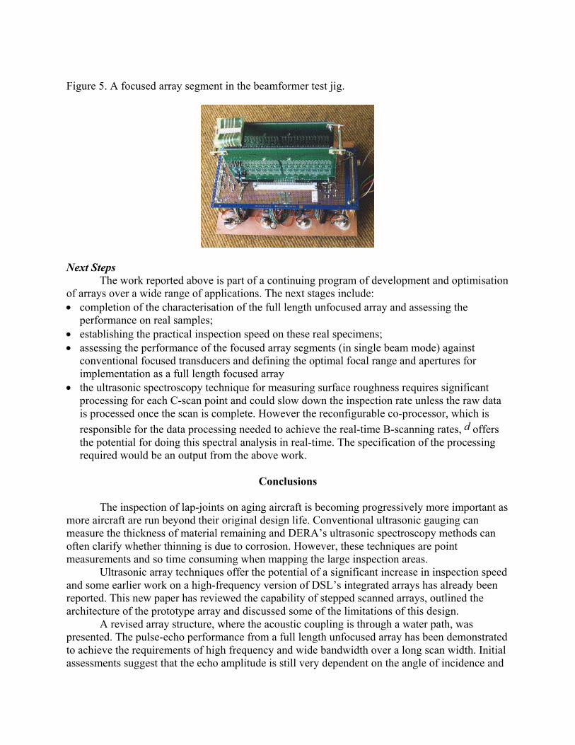
Figure 5. A focused array segment in the beamformer test jig.
Next Steps
The work reported above is part of a continuing program of development and optimisation of arrays over a wide range of applications. The next stages include: • completion of the characterisation of the full length unfocused array and assessing the
performance on real samples; • establishing the practical inspection speed on these real specimens; • assessing the performance of the focused array segments (in single beam mode) against
conventional focused transducers and defining the optimal focal range and apertures for implementation as a full length focused array
• the ultrasonic spectroscopy technique for measuring surface roughness requires significant processing for each C-scan point and could slow down the inspection rate unless the raw data is processed once the scan is complete. However the reconfigurable co-processor, which is responsible for the data processing needed to achieve the real-time B-scanning rates, d offers the potential for doing this spectral analysis in real-time. The specification of the processing required would be an output from the above work.
Conclusions
The inspection of lap-joints on aging aircraft is becoming progressively more important as
more aircraft are run beyond their original design life. Conventional ultrasonic gauging can measure the thickness of material remaining and DERA’s ultrasonic spectroscopy methods can often clarify whether thinning is due to corrosion. However, these techniques are point measurements and so time consuming when mapping the large inspection areas.
Ultrasonic array techniques offer the potential of a significant increase in inspection speed and some earlier work on a high-frequency version of DSL’s integrated arrays has already been reported. This new paper has reviewed the capability of stepped scanned arrays, outlined the architecture of the prototype array and discussed some of the limitations of this design.
A revised array structure, where the acoustic coupling is through a water path, was presented. The pulse-echo performance from a full length unfocused array has been demonstrated to achieve the requirements of high frequency and wide bandwidth over a long scan width. Initial assessments suggest that the echo amplitude is still very dependent on the angle of incidence and

care will have to be taken to control this in practice or to use techniques which are more tolerant of this effect, possibly by focusing. The scan speeds and performance will now be assessed on real samples.
Segments of arrays with different focus have been fabricated and will now be compared with the performance of conventional focused probes to establish the optimal specification for a full length focused array.
These arrays have a generic interface which allows them to be used with equipment ranging from conventional flaw detectors, through C-scan mapping systems such as ANDSCAN®, to real-time B-scanning equipment. Although the array frequency and beam characteristics were chosen to address the problem of lap-joint inspection, the techniques are equally valid for many other applications where large areas have to be inspected.
Acknowledgements The authors would like to acknowledge Jeremy Bennett’s contribution to the original design of the lap-joint array. © British Crown Copyright, Published with the permission of the Defence Evaluation and Research Agency on behalf of the controller of Her Britannic Majesty's Stationery Office, 1999.
REFERENCES a. Smith, RA, 1995, Non-destructive evaluation for corrosion in ageing aircraft, Part 1. Introduction, ultrasonic and eddy-current methods, INSIGHT, Vol.37, pp.798-807. b. Smith, RA, Bruce, DA, 1998, An ultrasonic spectroscopy method for measuring the roughness of hidden corrosion surfaces, Proceedings of NDT'98, The British Institute of NDT (isbn 0 903132 26 5), pp.167-170. c. Lines, DIA, 1998, Rapid inspection using integrated ultrasonic arrays, INSIGHT, Vol.40, pp.573-577. d. Lines, DIA, Dickson, KRD, Filippi, G, 1999, Rapid manual inspection and mapping using integrated ultrasonic arrays, Proceedings of 2nd International Conference on Emerging Technologies in NDT, Athens. e. Willsher, SJ, Smith RA, 1998, Multi-element ultrasonic scanning of in-service airframes, INSIGHT, Vol.40, pp.154-159. f. Smith, RA, Willsher, SJ, 1998, Multi-element ultrasonic linear arrays for rapid lap-joint inspection, Proceedings of 2nd Joint NASA/DoD/FAA Conference on Aging Aircraft, Williamsburg, NASA/CP – 1999 – 208982/Part 1, pp 294-302, 1999. g. Smith, RA, Willsher, SJ, 1998, Multi-element ultrasonic transducers for rapid lap-joint inspection, Proceedings of NDT'98, The British Institute of NDT (isbn 0 903132 26 5), pp.87-90. h. Drinkwater, B, Cawley, P, 1994, An ultrasonic wheel probe alternative to liquid coupling, INSIGHT, Vol.36, pp.430-433.