multi-flow technical properties - nilex incnilex.com/sites/default/files/nilex-multi-flow-athletic...
TRANSCRIPT
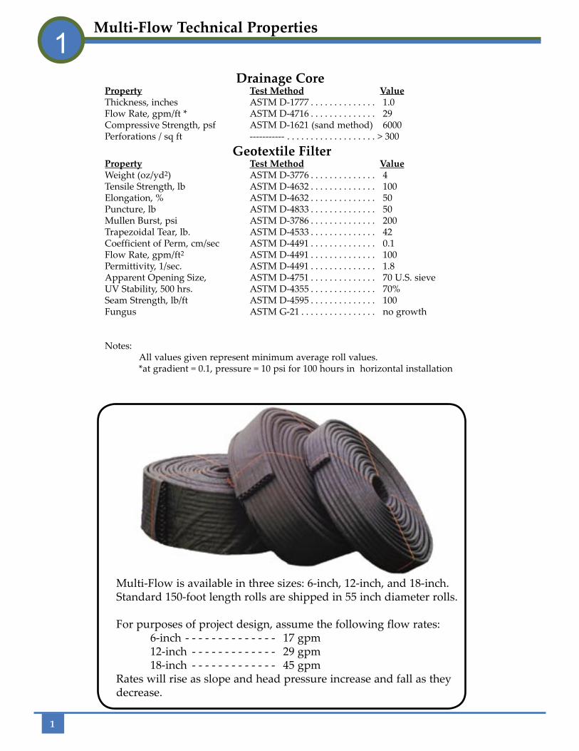
Drainage CoreProperty Test Method Value Thickness, inches ASTM D-1777 . . . . . . . . . . . . . . 1.0 Flow Rate, gpm/ft * ASTM D-4716 . . . . . . . . . . . . . . 29 Compressive Strength, psf ASTM D-1621 (sand method) 6000 Perforations / sq ft ----------- . . . . . . . . . . . . . . . . . . . > 300
Geotextile FilterProperty Test Method ValueWeight (oz/yd2) ASTM D-3776 . . . . . . . . . . . . . . 4Tensile Strength, lb ASTM D-4632 . . . . . . . . . . . . . . 100Elongation, % ASTM D-4632 . . . . . . . . . . . . . . 50Puncture, lb ASTM D-4833 . . . . . . . . . . . . . . 50Mullen Burst, psi ASTM D-3786 . . . . . . . . . . . . . . 200Trapezoidal Tear, lb. ASTM D-4533 . . . . . . . . . . . . . . 42Coefficient of Perm, cm/sec ASTM D-4491 . . . . . . . . . . . . . . 0.1Flow Rate, gpm/ft2 ASTM D-4491 . . . . . . . . . . . . . . 100Permittivity, 1/sec. ASTM D-4491 . . . . . . . . . . . . . . 1.8Apparent Opening Size, ASTM D-4751 . . . . . . . . . . . . . . 70 U.S. sieveUV Stability, 500 hrs. ASTM D-4355 . . . . . . . . . . . . . . 70%Seam Strength, lb/ft ASTM D-4595 . . . . . . . . . . . . . . 100Fungus ASTM G-21 . . . . . . . . . . . . . . . . no growth
Notes: All values given represent minimum average roll values. *at gradient = 0.1, pressure = 10 psi for 100 hours in horizontal installation
Multi-Flow is available in three sizes: 6-inch, 12-inch, and 18-inch. Standard 150-foot length rolls are shipped in 55 inch diameter rolls.
For purposes of project design, assume the following flow rates: 6-inch - - - - - - - - - - - - - - 17 gpm 12-inch - - - - - - - - - - - - - 29 gpm 18-inch - - - - - - - - - - - - - 45 gpmRates will rise as slope and head pressure increase and fall as they decrease.
Multi-Flow Technical Properties1
1
2
Basic Principles of Drainage2
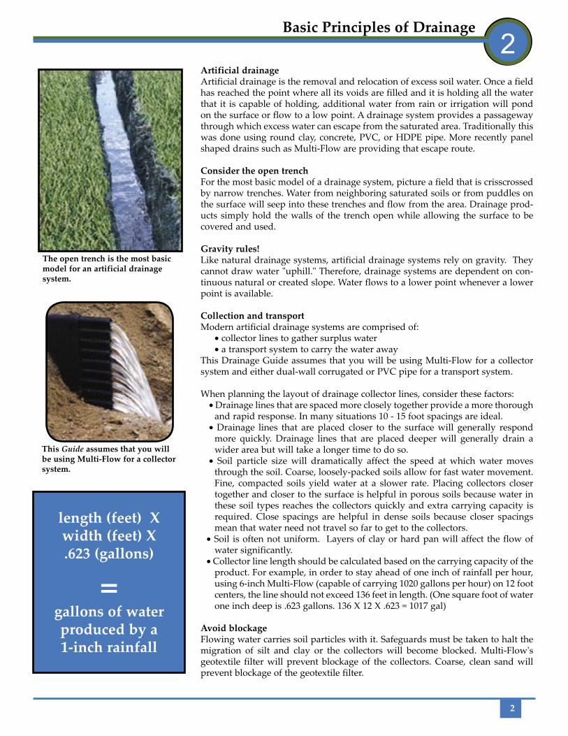
The open trench is the most basic model for an artificial drainage system.
length (feet) X width (feet) X .623 (gallons)
=gallons of water produced by a 1-inch rainfall
Artificial drainageArtificial drainage is the removal and relocation of excess soil water. Once a field has reached the point where all its voids are filled and it is holding all the water that it is capable of holding, additional water from rain or irrigation will pond on the surface or flow to a low point. A drainage system provides a passageway through which excess water can escape from the saturated area. Traditionally this was done using round clay, concrete, PVC, or HDPE pipe. More recently panel shaped drains such as Multi-Flow are providing that escape route.
Consider the open trenchFor the most basic model of a drainage system, picture a field that is crisscrossed by narrow trenches. Water from neighboring saturated soils or from puddles on the surface will seep into these trenches and flow from the area. Drainage prod-ucts simply hold the walls of the trench open while allowing the surface to be covered and used.
Gravity rules!Like natural drainage systems, artificial drainage systems rely on gravity. They cannot draw water "uphill." Therefore, drainage systems are dependent on con-tinuous natural or created slope. Water flows to a lower point whenever a lower point is available.
Collection and transportModern artificial drainage systems are comprised of:
• collector lines to gather surplus water • a transport system to carry the water away
This Drainage Guide assumes that you will be using Multi-Flow for a collector system and either dual-wall corrugated or PVC pipe for a transport system.
When planning the layout of drainage collector lines, consider these factors:• Drainage lines that are spaced more closely together provide a more thorough
and rapid response. In many situations 10 - 15 foot spacings are ideal.• Drainage lines that are placed closer to the surface will generally respond
more quickly. Drainage lines that are placed deeper will generally drain a wider area but will take a longer time to do so.
• Soil particle size will dramatically affect the speed at which water moves through the soil. Coarse, loosely-packed soils allow for fast water movement. Fine, compacted soils yield water at a slower rate. Placing collectors closer together and closer to the surface is helpful in porous soils because water in these soil types reaches the collectors quickly and extra carrying capacity is required. Close spacings are helpful in dense soils because closer spacings mean that water need not travel so far to get to the collectors.
• Soil is often not uniform. Layers of clay or hard pan will affect the flow of water significantly.
• Collector line length should be calculated based on the carrying capacity of the product. For example, in order to stay ahead of one inch of rainfall per hour, using 6-inch Multi-Flow (capable of carrying 1020 gallons per hour) on 12 foot centers, the line should not exceed 136 feet in length. (One square foot of water one inch deep is .623 gallons. 136 X 12 X .623 = 1017 gal)
Avoid blockageFlowing water carries soil particles with it. Safeguards must be taken to halt the migration of silt and clay or the collectors will become blocked. Multi-Flow's geotextile filter will prevent blockage of the collectors. Coarse, clean sand will prevent blockage of the geotextile filter.
This Guide assumes that you will be using Multi-Flow for a collector system.
Drainage CoreProperty Test Method Value Thickness, inches ASTM D-1777 . . . . . . . . . . . . . . 1.0 Flow Rate, gpm/ft * ASTM D-4716 . . . . . . . . . . . . . . 29 Compressive Strength, psf ASTM D-1621 (sand method) 6000 Perforations / sq ft ----------- . . . . . . . . . . . . . . . . . . . > 300
Geotextile FilterProperty Test Method ValueWeight (oz/yd2) ASTM D-3776 . . . . . . . . . . . . . . 4Tensile Strength, lb ASTM D-4632 . . . . . . . . . . . . . . 100Elongation, % ASTM D-4632 . . . . . . . . . . . . . . 50Puncture, lb ASTM D-4833 . . . . . . . . . . . . . . 50Mullen Burst, psi ASTM D-3786 . . . . . . . . . . . . . . 200Trapezoidal Tear, lb. ASTM D-4533 . . . . . . . . . . . . . . 42Coefficient of Perm, cm/sec ASTM D-4491 . . . . . . . . . . . . . . 0.1Flow Rate, gpm/ft2 ASTM D-4491 . . . . . . . . . . . . . . 100Permittivity, 1/sec. ASTM D-4491 . . . . . . . . . . . . . . 1.8Apparent Opening Size, ASTM D-4751 . . . . . . . . . . . . . . 70 U.S. sieveUV Stability, 500 hrs. ASTM D-4355 . . . . . . . . . . . . . . 70%Seam Strength, lb/ft ASTM D-4595 . . . . . . . . . . . . . . 100Fungus ASTM G-21 . . . . . . . . . . . . . . . . no growth
Notes: All values given represent minimum average roll values. *at gradient = 0.1, pressure = 10 psi for 100 hours in horizontal installation

3
1. TrenchingIn most natural turf situations, it is best to install Multi-Flow vertically. A 4 inch wide trench is ideal both for performance and ease of installation. It produces little spoil and results in excellent drainage because it takes advantage of Multi-Flow's significant vertical footprint. Installation methods that use a combination trencher/conveyor can trench and remove spoil in one efficient operation.
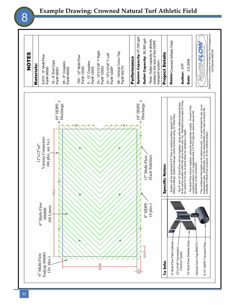
2. Layout patterna. Crowned or sloped fieldsIf the surface of the field has a consistent slope (.5% or greater), it is advised that the collector lines be placed such that they intersect the water flow direction. Placing the lines at a 90 degree angle to the flow direction and running toward the end zone is usually not the best policy. The resulting lines would be too long and, in order to maintain fall, excessively deep. A 45 degree angle running toward the sidelines works well because it allows the lines to maintain grade while also intercepting the direction of surface water flow. The resulting herringbone pat-tern complements the existing field contour, providing effective drainage as well as an uncomplicated installation. (See example drawing on page 11)
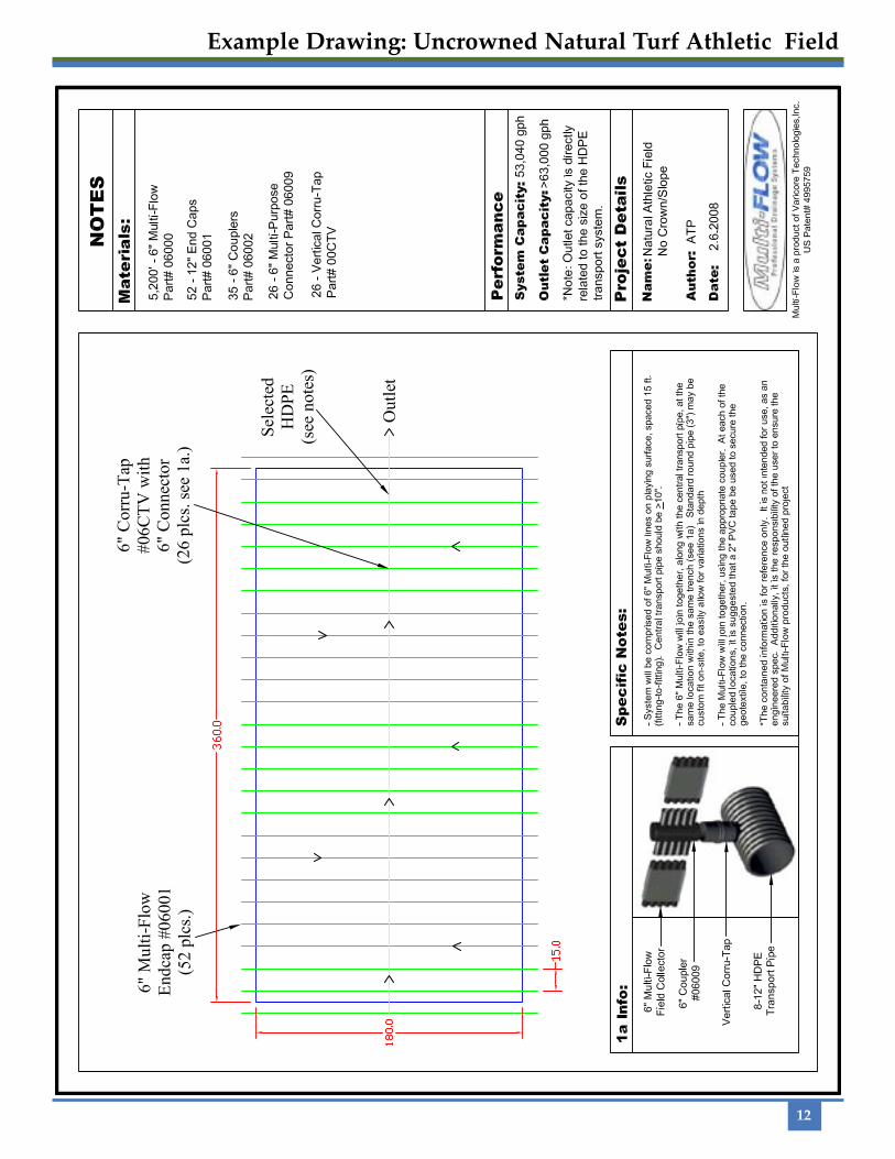
b. Flat or irregular fieldsIf the field is flat, or has less than a .5% slope from the center, a parallel drainage pattern may be appropriate. Since the water will basically stand on the surface of a flat field, there is no advantage in attempting to place drainage lines in the flow path. Collectors could run toward the sidelines or the center of the field. On flat fields, proper grade needs to be maintained by increasing the depth of the trench. (See example drawing on page 12)
3. CoverageThe drainage pattern should extend 10 to 15 feet beyond the field to include the intensively used sideline area. Six-inch Multi-Flow is ideal for these on-field col-lectors. It is also advisable to provide for drainage along the side of the field. This is especially critical when the field is surrounded by a running track or other adja-cent features that slope toward the field. This can be accomplished by including a line of Multi-Flow above a non-perforated transport pipe (typically PVC) or by using a perforated round pipe (typically corrugated) as a transport pipe.
4. Collector line spacingPlacing collector lines 10 feet apart, outlet to outlet, provides excellent reaction time and uniform drainage performance. 15 feet apart provides an adequate system. A field employing 20 foot spacings will require a longer waiting period before use after a rainfall event.
An example will illustrate the consequences of line spacings. Assume 40 lines of 6-inch Multi-Flow in an area 210 feet by 400 feet (10 foot spacings). This will pro-vide capacity to handle a maximum of 1.56 inches an hour, assuming:
• 17 gpm x 40 lines = 680 gallons per minute each side of the field • 680 gpm x 2 sides = 1,360 gallons per minute • 1360 gpm x 60 minutes = 81,600 gallons per hour • 210 feet by 400 feet = 84,000 ft2
• 81,600 gph / 84,000 sq/ft = .971 gallons per sq/ft per hr • .971 gal/sq ft/hr = 1.56 inches of rainfall per hour (.971/.623)
Capacity could be increased by adding more Multi Flow drainage lines.
Three factors will determine the line spacing decisions:1.) anticipated field usage schedule 2.) local rainfall events 3.) project budget
Natural Turf Athletic Fields: Vertical Installation3
A 4-inch trench produces only a mod-erate quantity of spoil but allows ample room to encase Multi-Flow in filter sand.
Intensively used surfaces require inten-sive drainage to maximize usage time and reduce compaction.
Lines laid out in a herringbone pattern on a crowned field intercept water mov-ing toward the side of the field.
4
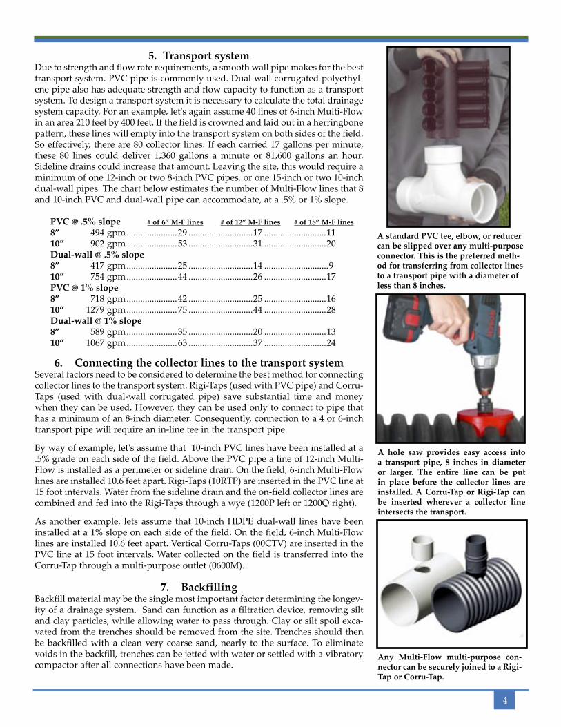
A standard PVC tee, elbow, or reducer can be slipped over any multi-purpose connector. This is the preferred meth-od for transferring from collector lines to a transport pipe with a diameter of less than 8 inches.
A hole saw provides easy access into a transport pipe, 8 inches in diameter or larger. The entire line can be put in place before the collector lines are installed. A Corru-Tap or Rigi-Tap can be inserted wherever a collector line intersects the transport.
Any Multi-Flow multi-purpose con-nector can be securely joined to a Rigi-Tap or Corru-Tap.
5. Transport systemDue to strength and flow rate requirements, a smooth wall pipe makes for the best transport system. PVC pipe is commonly used. Dual-wall corrugated polyethyl-ene pipe also has adequate strength and flow capacity to function as a transport system. To design a transport system it is necessary to calculate the total drainage system capacity. For an example, let's again assume 40 lines of 6-inch Multi-Flow in an area 210 feet by 400 feet. If the field is crowned and laid out in a herringbone pattern, these lines will empty into the transport system on both sides of the field. So effectively, there are 80 collector lines. If each carried 17 gallons per minute, these 80 lines could deliver 1,360 gallons a minute or 81,600 gallons an hour. Sideline drains could increase that amount. Leaving the site, this would require a minimum of one 12-inch or two 8-inch PVC pipes, or one 15-inch or two 10-inch dual-wall pipes. The chart below estimates the number of Multi-Flow lines that 8 and 10-inch PVC and dual-wall pipe can accommodate, at a .5% or 1% slope.
PVC @ .5% slope # of 6” M-F lines # of 12” M-F lines # of 18” M-F lines8” 494 gpm ......................29 ............................17 ...........................1110” 902 gpm .....................53 ............................31 ...........................20Dual-wall @ .5% slope8” 417 gpm ......................25 ............................14 ............................910” 754 gpm ......................44 ............................26 ...........................17PVC @ 1% slope8” 718 gpm ......................42 ............................25 ...........................1610” 1279 gpm ......................75 ............................44 ...........................28Dual-wall @ 1% slope8” 589 gpm ......................35 ............................20 ...........................1310” 1067 gpm ......................63 ............................37 ...........................24
6. Connecting the collector lines to the transport systemSeveral factors need to be considered to determine the best method for connecting collector lines to the transport system. Rigi-Taps (used with PVC pipe) and Corru-Taps (used with dual-wall corrugated pipe) save substantial time and money when they can be used. However, they can be used only to connect to pipe that has a minimum of an 8-inch diameter. Consequently, connection to a 4 or 6-inch transport pipe will require an in-line tee in the transport pipe.
By way of example, let's assume that 10-inch PVC lines have been installed at a .5% grade on each side of the field. Above the PVC pipe a line of 12-inch Multi-Flow is installed as a perimeter or sideline drain. On the field, 6-inch Multi-Flow lines are installed 10.6 feet apart. Rigi-Taps (10RTP) are inserted in the PVC line at 15 foot intervals. Water from the sideline drain and the on-field collector lines are combined and fed into the Rigi-Taps through a wye (1200P left or 1200Q right).
As another example, lets assume that 10-inch HDPE dual-wall lines have been installed at a 1% slope on each side of the field. On the field, 6-inch Multi-Flow lines are installed 10.6 feet apart. Vertical Corru-Taps (00CTV) are inserted in the PVC line at 15 foot intervals. Water collected on the field is transferred into the Corru-Tap through a multi-purpose outlet (0600M).
7. BackfillingBackfill material may be the single most important factor determining the longev-ity of a drainage system. Sand can function as a filtration device, removing silt and clay particles, while allowing water to pass through. Clay or silt spoil exca-vated from the trenches should be removed from the site. Trenches should then be backfilled with a clean very coarse sand, nearly to the surface. To eliminate voids in the backfill, trenches can be jetted with water or settled with a vibratory compactor after all connections have been made.
5
1. Don't forget the drainageIn synthetic turf applications, drainage is frequently ignored or under engineered. Allowing water to build up on the compacted base will soften and destabilize the base and result in an uneven surface. Allowing water to accumulate on the synthetic surface results in stretched and ill-fitting turf.
2. No trenching requiredIn synthetic turf applications, it is best to install Multi-Flow flat. Collector lines can be positioned horizontally directly on the compacted base, or on top of the geotextile soil separator if one is used. No costly and time con-suming trenching is needed. Multi-Flow's ample surface area and enclosed circular flow channels allow for rapid water intake and prompt removal.
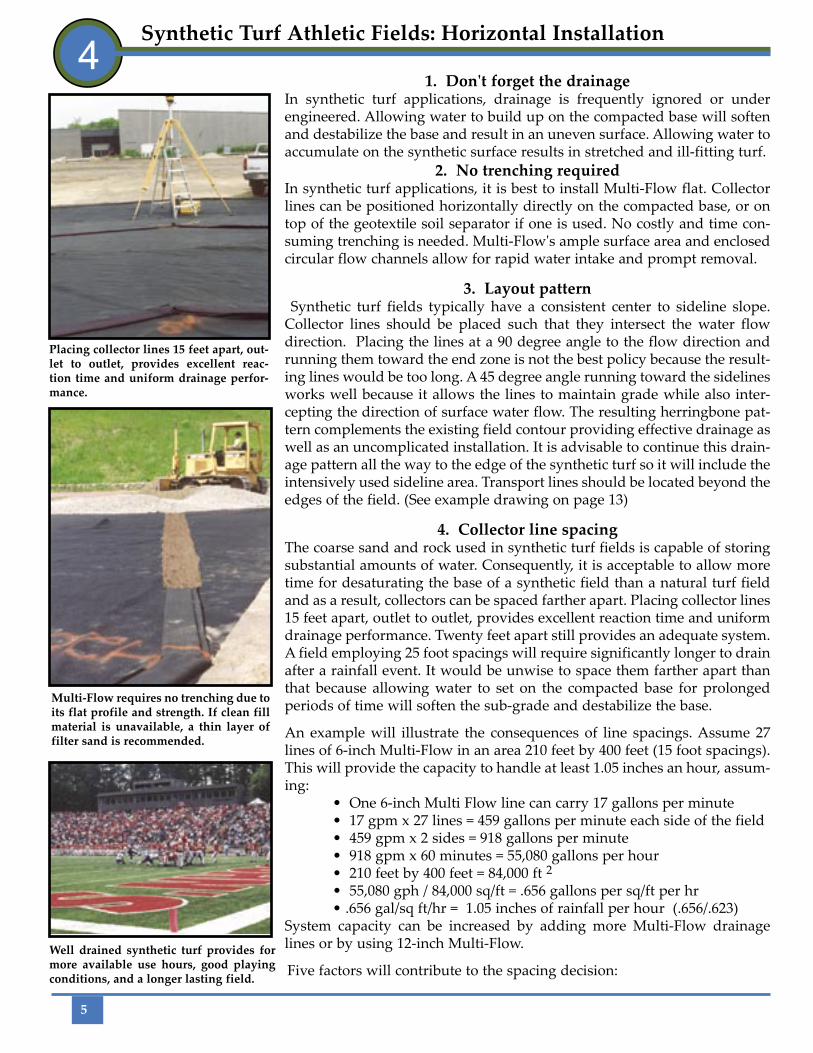
3. Layout pattern Synthetic turf fields typically have a consistent center to sideline slope. Collector lines should be placed such that they intersect the water flow direction. Placing the lines at a 90 degree angle to the flow direction and running them toward the end zone is not the best policy because the result-ing lines would be too long. A 45 degree angle running toward the sidelines works well because it allows the lines to maintain grade while also inter-cepting the direction of surface water flow. The resulting herringbone pat-tern complements the existing field contour providing effective drainage as well as an uncomplicated installation. It is advisable to continue this drain-age pattern all the way to the edge of the synthetic turf so it will include the intensively used sideline area. Transport lines should be located beyond the edges of the field. (See example drawing on page 13)
4. Collector line spacingThe coarse sand and rock used in synthetic turf fields is capable of storing substantial amounts of water. Consequently, it is acceptable to allow more time for desaturating the base of a synthetic field than a natural turf field and as a result, collectors can be spaced farther apart. Placing collector lines 15 feet apart, outlet to outlet, provides excellent reaction time and uniform drainage performance. Twenty feet apart still provides an adequate system. A field employing 25 foot spacings will require significantly longer to drain after a rainfall event. It would be unwise to space them farther apart than that because allowing water to set on the compacted base for prolonged periods of time will soften the sub-grade and destabilize the base.
An example will illustrate the consequences of line spacings. Assume 27 lines of 6-inch Multi-Flow in an area 210 feet by 400 feet (15 foot spacings). This will provide the capacity to handle at least 1.05 inches an hour, assum-ing:
• One 6-inch Multi Flow line can carry 17 gallons per minute • 17 gpm x 27 lines = 459 gallons per minute each side of the field • 459 gpm x 2 sides = 918 gallons per minute • 918 gpm x 60 minutes = 55,080 gallons per hour • 210 feet by 400 feet = 84,000 ft 2 • 55,080 gph / 84,000 sq/ft = .656 gallons per sq/ft per hr • .656 gal/sq ft/hr = 1.05 inches of rainfall per hour (.656/.623)
System capacity can be increased by adding more Multi-Flow drainage lines or by using 12-inch Multi-Flow.
Five factors will contribute to the spacing decision:
Synthetic Turf Athletic Fields: Horizontal Installation4
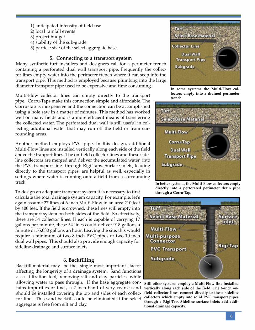
Multi-Flow requires no trenching due to its flat profile and strength. If clean fill material is unavailable, a thin layer of filter sand is recommended.
Placing collector lines 15 feet apart, out-let to outlet, provides excellent reac-tion time and uniform drainage perfor-mance.
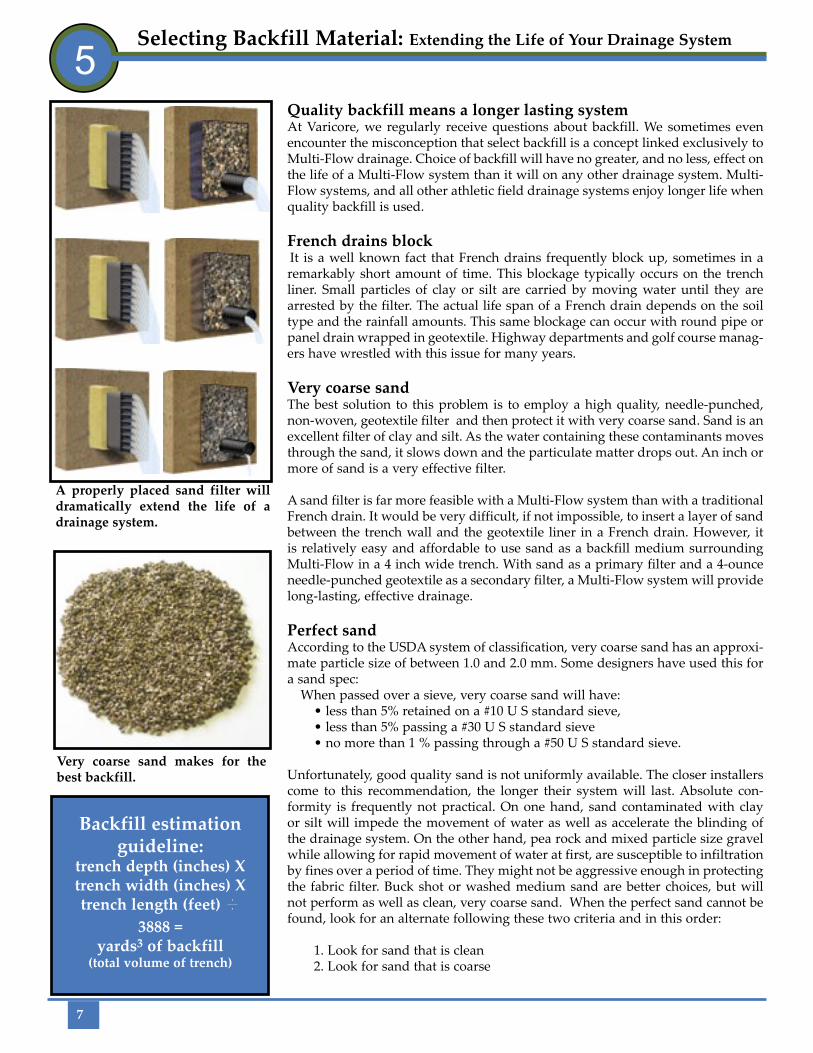
Well drained synthetic turf provides for more available use hours, good playing conditions, and a longer lasting field.
1) anticipated intensity of field use 2) local rainfall events 3) project budget 4) stability of the sub-grade 5) particle size of the select aggregate base
5. Connecting to a transport systemMany synthetic turf installers and designers call for a perimeter trench containing a perforated dual wall transport pipe. Frequently the collec-tor lines empty water into the perimeter trench where it can seep into the transport pipe. This method is employed because plumbing into the large diameter transport pipe used to be expensive and time consuming.
6
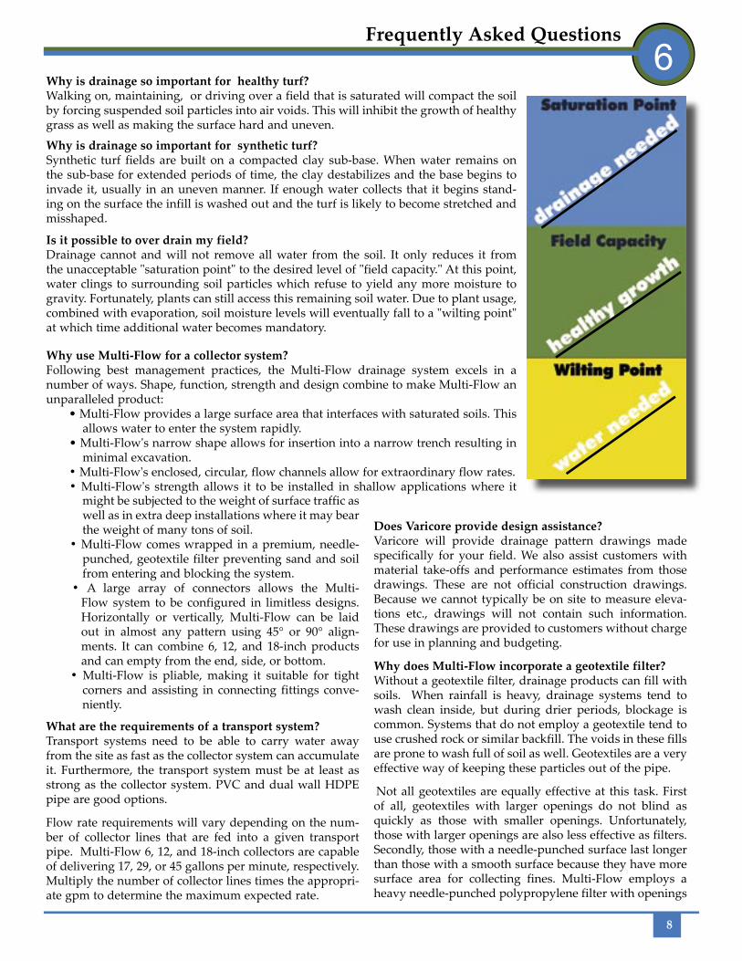
In some systems the Multi-Flow col-lectors empty into a drained perimeter trench.
In better systems, the Multi-Flow collectors empty directly into a perforated perimeter drain pipe through a Corru-Tap.
Still other systems employ a Multi-Flow line installed vertically along each side of the field. The 6-inch on-field collector lines connect directly to these sideline collectors which empty into solid PVC transport pipes through a Rigi-Tap. Sideline surface inlets add addi-tional drainage capacity.
6. BackfillingBackfill material may be the single most important factor affecting the longevity of a drainage system. Sand functions as a filtration tool, removing silt and clay particles, while allowing water to pass through. If the base aggregate con-tains impurities or fines, a 2-inch band of very coarse sand should be installed covering the top and sides of each collec-tor line. This sand backfill could be eliminated if the select aggregate is free from silt and clay.
To design an adequate transport system it is necessary to first calculate the total drainage system capacity. For example, let's again assume 27 lines of 6-inch Multi-Flow in an area 210 feet by 400 feet. If the field is crowned, these lines will empty into the transport system on both sides of the field. So effectively, there are 54 collector lines. If each is capable of carrying 17 gallons per minute, these 54 lines could deliver 918 gallons a minute or 55,080 gallons an hour. Leaving the site, this would require a minimum of two 8-inch PVC pipes or two 10-inch dual wall pipes. This should also provide enough capacity for sideline drainage and surface inlets.
Multi-Flow collector lines can empty directly to the transport pipe. Corru-Taps make this connection simple and affordable. The Corru-Tap is inexpensive and the connection can be accomplished using a hole saw in a matter of minutes. This method has worked well on many fields and is a more efficient means of transferring the collected water. The perforated dual wall is still useful in col-lecting additional water that may run off the field or from sur-rounding areas.
Another method employs PVC pipe. In this design, additional Multi-Flow lines are installed vertically along each side of the field above the tranport lines. The on-field collector lines and these side-line collectors are merged and deliver the accumulated water into the PVC transport line through Rigi-Taps. Surface inlets, leading directly to the transport pipes, are helpful as well, especially in settings where water is running onto a field from a surrounding track.
7
Selecting Backfill Material: Extending the Life of Your Drainage System
5Quality backfill means a longer lasting systemAt Varicore, we regularly receive questions about backfill. We sometimes even encounter the misconception that select backfill is a concept linked exclusively to Multi-Flow drainage. Choice of backfill will have no greater, and no less, effect on the life of a Multi-Flow system than it will on any other drainage system. Multi-Flow systems, and all other athletic field drainage systems enjoy longer life when quality backfill is used.
French drains blockIt is a well known fact that French drains frequently block up, sometimes in a remarkably short amount of time. This blockage typically occurs on the trench liner. Small particles of clay or silt are carried by moving water until they are arrested by the filter. The actual life span of a French drain depends on the soil type and the rainfall amounts. This same blockage can occur with round pipe or panel drain wrapped in geotextile. Highway departments and golf course manag-ers have wrestled with this issue for many years.
Very coarse sandThe best solution to this problem is to employ a high quality, needle-punched, non-woven, geotextile filter and then protect it with very coarse sand. Sand is an excellent filter of clay and silt. As the water containing these contaminants moves through the sand, it slows down and the particulate matter drops out. An inch or more of sand is a very effective filter.
A sand filter is far more feasible with a Multi-Flow system than with a traditional French drain. It would be very difficult, if not impossible, to insert a layer of sand between the trench wall and the geotextile liner in a French drain. However, it is relatively easy and affordable to use sand as a backfill medium surrounding Multi-Flow in a 4 inch wide trench. With sand as a primary filter and a 4-ounce needle-punched geotextile as a secondary filter, a Multi-Flow system will provide long-lasting, effective drainage.
Perfect sandAccording to the USDA system of classification, very coarse sand has an approxi-mate particle size of between 1.0 and 2.0 mm. Some designers have used this for a sand spec:
When passed over a sieve, very coarse sand will have: • less than 5% retained on a #10 U S standard sieve, • less than 5% passing a #30 U S standard sieve • no more than 1 % passing through a #50 U S standard sieve.
Unfortunately, good quality sand is not uniformly available. The closer installers come to this recommendation, the longer their system will last. Absolute con-formity is frequently not practical. On one hand, sand contaminated with clay or silt will impede the movement of water as well as accelerate the blinding of the drainage system. On the other hand, pea rock and mixed particle size gravel while allowing for rapid movement of water at first, are susceptible to infiltration by fines over a period of time. They might not be aggressive enough in protecting the fabric filter. Buck shot or washed medium sand are better choices, but will not perform as well as clean, very coarse sand. When the perfect sand cannot be found, look for an alternate following these two criteria and in this order:
1. Look for sand that is clean 2. Look for sand that is coarse
Very coarse sand makes for the best backfill.
Backfill estimation guideline:
trench depth (inches) Xtrench width (inches) Xtrench length (feet) I
3888 =yards3 of backfill
(total volume of trench)
A properly placed sand filter will dramatically extend the life of a drainage system.
8
Frequently Asked Questions6
Why is drainage so important for healthy turf?Walking on, maintaining, or driving over a field that is saturated will compact the soil by forcing suspended soil particles into air voids. This will inhibit the growth of healthy grass as well as making the surface hard and uneven.
Why is drainage so important for synthetic turf?Synthetic turf fields are built on a compacted clay sub-base. When water remains on the sub-base for extended periods of time, the clay destabilizes and the base begins to invade it, usually in an uneven manner. If enough water collects that it begins stand-ing on the surface the infill is washed out and the turf is likely to become stretched and misshaped.
Is it possible to over drain my field?Drainage cannot and will not remove all water from the soil. It only reduces it from the unacceptable "saturation point" to the desired level of "field capacity." At this point, water clings to surrounding soil particles which refuse to yield any more moisture to gravity. Fortunately, plants can still access this remaining soil water. Due to plant usage, combined with evaporation, soil moisture levels will eventually fall to a "wilting point" at which time additional water becomes mandatory.
Why use Multi-Flow for a collector system?Following best management practices, the Multi-Flow drainage system excels in a number of ways. Shape, function, strength and design combine to make Multi-Flow an unparalleled product:
• Multi-Flow provides a large surface area that interfaces with saturated soils. This allows water to enter the system rapidly.
• Multi-Flow's narrow shape allows for insertion into a narrow trench resulting in minimal excavation.
• Multi-Flow's enclosed, circular, flow channels allow for extraordinary flow rates.• Multi-Flow's strength allows it to be installed in shallow applications where it
might be subjected to the weight of surface traffic as well as in extra deep installations where it may bear the weight of many tons of soil.
• Multi-Flow comes wrapped in a premium, needle-punched, geotextile filter preventing sand and soil from entering and blocking the system.
• A large array of connectors allows the Multi-Flow system to be configured in limitless designs. Horizontally or vertically, Multi-Flow can be laid out in almost any pattern using 45° or 90° align-ments. It can combine 6, 12, and 18-inch products and can empty from the end, side, or bottom.
• Multi-Flow is pliable, making it suitable for tight corners and assisting in connecting fittings conve-niently.
What are the requirements of a transport system?Transport systems need to be able to carry water away from the site as fast as the collector system can accumulate it. Furthermore, the transport system must be at least as strong as the collector system. PVC and dual wall HDPE pipe are good options.
Flow rate requirements will vary depending on the num-ber of collector lines that are fed into a given transport pipe. Multi-Flow 6, 12, and 18-inch collectors are capable of delivering 17, 29, or 45 gallons per minute, respectively. Multiply the number of collector lines times the appropri-ate gpm to determine the maximum expected rate.
Does Varicore provide design assistance?Varicore will provide drainage pattern drawings made specifically for your field. We also assist customers with material take-offs and performance estimates from those drawings. These are not official construction drawings. Because we cannot typically be on site to measure eleva-tions etc., drawings will not contain such information. These drawings are provided to customers without charge for use in planning and budgeting.
Why does Multi-Flow incorporate a geotextile filter?Without a geotextile filter, drainage products can fill with soils. When rainfall is heavy, drainage systems tend to wash clean inside, but during drier periods, blockage is common. Systems that do not employ a geotextile tend to use crushed rock or similar backfill. The voids in these fills are prone to wash full of soil as well. Geotextiles are a very effective way of keeping these particles out of the pipe.
Not all geotextiles are equally effective at this task. First of all, geotextiles with larger openings do not blind as quickly as those with smaller openings. Unfortunately, those with larger openings are also less effective as filters. Secondly, those with a needle-punched surface last longer than those with a smooth surface because they have more surface area for collecting fines. Multi-Flow employs a heavy needle-punched polypropylene filter with openings
Corru-Tap H
9
as large as a # 70 U.S. standard sieve. Its openings are of optimum size and its "fuzzy" surface provides more filter capacity.
If I cannot find the recommended backfill medium should I select another drainage system?Obviously we would not want to see installers backfill Multi-Flow, or any other drainage product for that matter, with native soil. The system would quite likely suffer pre-mature failure. The customer might then blame the drain-age product instead of the real culprit, the fines, for that failure. We know that sometimes customers must settle for less than the very best. Any kind of select backfill is to be preferred over the native excavated soil. Multi-Flow's size and shape makes premium backfill a more realistic possi-bility than in a French drain system. However, that is only one of many attractive Multi-Flow features. Multi-Flow outperforms the competition with or without the very best backfill. It would be unfortunate if someone chose to install an inferior drainage product because of the illusion that it could be safely backfilled with inferior backfill.
Will my choice of backfill void Multi-Flow’s warranty?Multi-Flow's warranty is not affected by backfill choices. Varicore Technologies guarantees that each roll of pipe leaving our factory meets the high standard laid out on
our product spec sheet. Choice of backfill and installation techniques will in no way affect this warranty. Varicore manufactures the highest quality drainage products. So, it encourages the end user to insist on installation practices that insure the longest possible life and the highest level of performance from the drainage system.
How do I decide whether to install Multi-Flow horizon-tally or vertically?The unique features of your drainage site will determine the drainage profile. Vertical installations are most com-mon. They allow for installation in a narrow trench with less excavation, less spoil, and less backfilling. Horizontal installations are used when the situation calls for a low profile or to avoid trenching altogether. Typically vertical installations are used in natural turf fields and a horizontal profile is employed under synthetic turf.
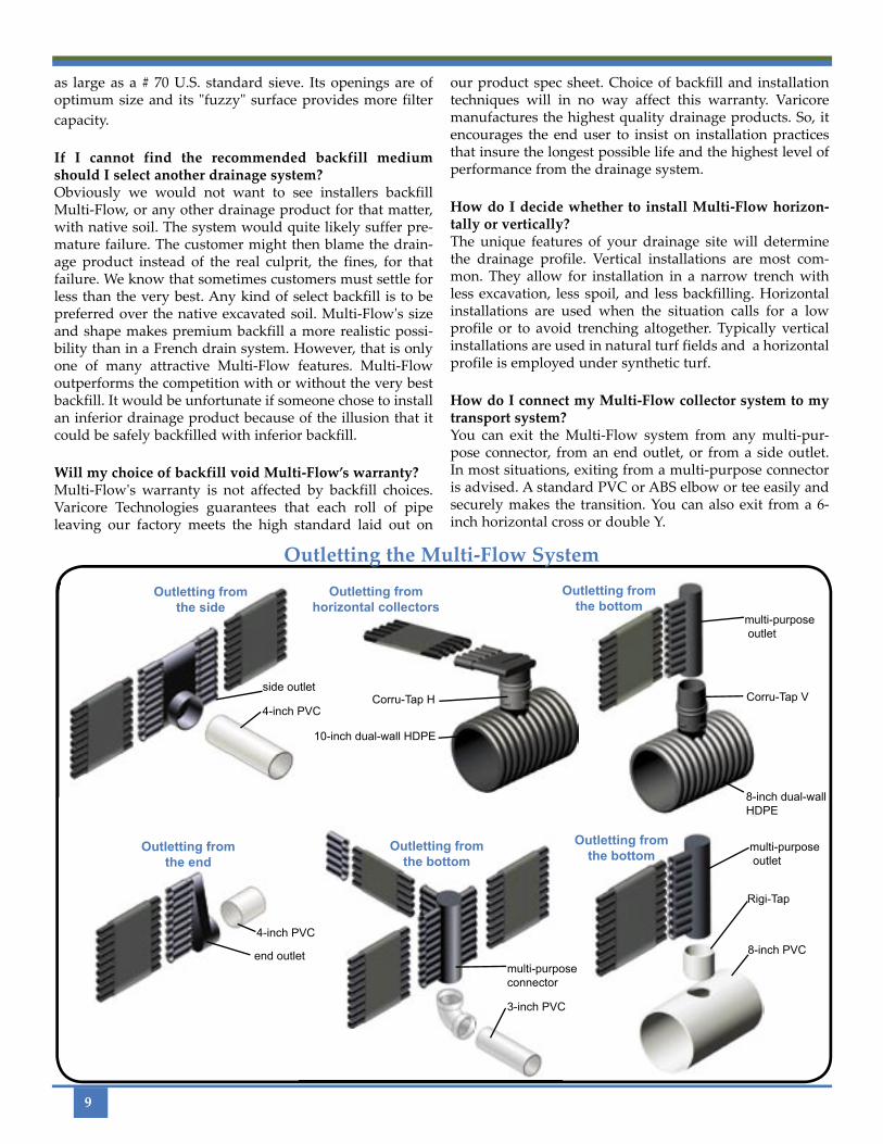
How do I connect my Multi-Flow collector system to my transport system?You can exit the Multi-Flow system from any multi-pur-pose connector, from an end outlet, or from a side outlet. In most situations, exiting from a multi-purpose connector is advised. A standard PVC or ABS elbow or tee easily and securely makes the transition. You can also exit from a 6-inch horizontal cross or double Y.
Outletting the Multi-Flow System
Outletting from the side
Outletting from the end
Outletting from the bottom
Outletting from horizontal collectors
Outletting from the bottom
Outletting from the bottom
end outlet
side outlet
multi-purpose outlet
multi-purpose connector
Rigi-Tap
Corru-Tap V
4-inch PVC
4-inch PVC
3-inch PVC
8-inch PVC
multi-purpose outlet
8-inch dual-wall HDPE
10-inch dual-wall HDPE

10
Example Design Details7
UNDER NATURAL TURF INSTALLATION
UNDER SYNTHETIC TURF INSTALLATION
Rigi-Tap
Corru-Tap V
8-inch PVC
(OPTIONAL DEPENDING ON THE QUALITY OF THE FILL MATERIAL)
11
Example Drawing: Crowned Natural Turf Athletic Field 8
12
Example Drawing: Uncrowned Natural Turf Athletic Field

13
Example Drawing: Synthetic Turf Athletic Field
14
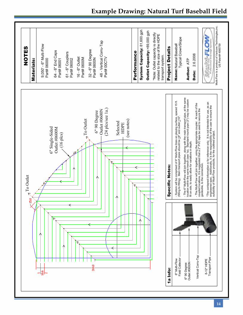
Example Drawing: Natural Turf Baseball Field