multi format lcd monitor dt-v9l5 -...
TRANSCRIPT
LCT2704-001A
For Customer Use:Enter below the Serial No. which is located on the rear of the cabinet. Retain this information for future reference.
Model No.Serial No.
: DT-V9L5:
MULTI FORMAT LCD MONITOR
INSTRUCTIONSDT-V9L5
®
DT-V9L5_EN_1.indb 1DT-V9L5_EN_1.indb 1 10/10/2012 5:18:31 PM10/10/2012 5:18:31 PM

2
Safety Precautions
WARNING: TO REDUCE RISK OF FIRE OR ELECTRIC SHOCK, DO NOT EXPOSE THIS APPARATUS TO RAIN OR MOISTURE. NO OBJECTS FILLED WITH LIQUIDS, SUCH AS VASES, SHALL BE PLACED ON THE APPARATUS.
IMPORTANT SAFEGUARDSElectrical energy can perform many useful functions. This unit has been engineered and manufactured to assure your personal safety. But IMPROPER USE CAN RESULT IN POTENTIAL ELECTRIC SHOCK OR FIRE. In order not to defeat the safeguards incorporated into this product, observe the following basic rules for its installation, use, and service. Please read these “IMPORTANT SAFEGUARDS” carefully before use.
All the safety and operating instructions should be read before the • product is operated.The safety and operating instructions should be retained for future • reference.All warnings on the product and in the operating instructions • should be adhered to.All operating instructions should be followed.•
POWER CONNECTIONThe power supply voltage rating of this product is AC 120 V.The power cord attached conforms to the following power supply voltage and countries. Use only the power cord designated to ensure safety and EMC regulations of each country.Not all types of power cords are supplied to this product.For U.S.A. and Canada: AC 120 V
This plug will fit only into a grounded power outlet. If you are unable to insert the plug into the outlet, contact your electrician to install the proper outlet. Do not defeat the safety purpose of the grounded plug.This product should be operated only with the type of power source indicated on the label. If you are not sure of the type of power supply of your home, consult your product dealer or local electric power company.
Warning: This is a class A product. In a domestic environment this product may cause radio interference in which case the user may be required to take adequate measures.
Before connecting other products such as VCR’s and personal • computers, you should turn off the power of this product for protection against electric shock.Do not use attachments not recommended by the • manufacturer as they may be hazardous.When replacement parts are required,• be sure the service technician has used replacement parts specified by the manufacturer or equivalents. Unauthorized substitutions may result in fire, electric shock, or other hazards.Upon completion of any service or repairs to this product,• ask the service technician to perform safety checks to determine that the product is in proper operating condition.
Under the following conditions,1. Turn off the power.2. Unplug this product from the wall outlet.3. Refer service to qualified service personnel.a) When the product emits smoke or unusual smell.b) When the product exhibits a distinct change in performance
—for example, no picture or no sound.c) If liquid has been spilled, or objects have fallen on the product.d) If the product has been exposed to rain or water.e) If the product has been dropped or damaged in any way.f) When the power supply cord or plug is damaged.
Do not install this product in the following places:• in a damp or dusty room –where the product is exposed to soot or steam, such as –near the cooking counter or a humidifier near heat sources –where condensation easily occurs, such as near the window –in a location exposed to direct sunlight or strong light –
Do not place this product on an unstable cart, stand, or table. • The product may fall, causing serious injury to a child or adult, and serious damage to the product.The product should be mounted according to the manufacturer’s instructions, and should use a mount recommended by the manufacturer.Do not use this product near water.• Be sure to install the product in the place where proper • temperature and humidity are kept (☞ “Operating conditions” on page 28).This product becomes hot during its use. Take enough care when handling the product.
CAUTION: To reduce the risk of electric shock. Do not remove cover (or back). No user serviceable parts inside. Refer servicing to qualified service personnel.
RISK OF ELECTRICAL SHOCKDO NOT OPEN
The lightning flash with arrowhead symbol, within an equilateral triangle is intended to alert the user to the presence of uninsulated “dangerous voltage” within the product’s enclosure that may be of sufficient magnitude to constitute a risk of electric shock to persons.
The exclamation point within an equilateral triangle is intended to alert the user to the presence of important operating and maintenance (servicing) instructions in the literature accompanying the appliance.
CAUTION
DT-V9L5_EN_1.indb 2DT-V9L5_EN_1.indb 2 10/10/2012 5:18:38 PM10/10/2012 5:18:38 PM
3
Do not use the product for a long time if the sound is distorted.
Do not attempt to service this product yourself, as opening or removing covers may expose you to dangerous voltages and other hazards. Refer all service to qualified service personnel.
Use only the power source specified on the unit.AC power: 120 V, 50 Hz/60 Hz• DC power: 12 V — 17 V•
The AC power supply is controlled by turning on/off the POWER • switch on the rear panel. If the product is installed in a place where you cannot easily turn on/off the POWER switch, control the AC power supply by plugging/unplugging the power cord into/from the AC outlet. In this case, install the product as close to the AC outlet as possible, and leave enough space for plugging/unplugging the power cord. If the product is installed in a place where you cannot easily plug/unplug the power cord, equip an easily accessible device to the wiring of the building for turning on/off the power.When the product is left unattended and unused for a long • period of time, unplug it from the wall outlet and disconnect the cable system.Do not overload wall outlets, extension cords, or convenience • receptacles on other equipment as this can result in a risk of fire or electric shock.Use only the accessory cord designed for this product to • prevent shock.
Slots and openings in the cabinet are provided for ventilation. These ensure reliable operation of the product and protect it from • overheating. These openings must not be blocked or covered.Never push objects of any kind into this product through openings as they may touch dangerous voltage points or short-circuit the parts, • which could result in a fire or electric shock.Never spill liquid of any kind on the product.• Never place anything on the product. (Placing liquids, naked flames, cloths, paper, etc. on the product may cause a fire.)• Do not apply any strong shock to the LCD panel. (Do not hit any object against it or push it with a sharp-pointed tool.)• Do not put heavy objects on the product.• Do not step on or hang on the product.•
FCC NOTICECAUTION: Changes or modifications not approved by JVC could void the user’s authority to operate the equipment.NOTE: This equipment has been tested and found to comply with the limits for a Class A digital device, pursuant to Part 15 of the FCC Rules. These limits are designed to provide reasonable protection against harmful interference when the equipment is operated in a commercial environment. This equipment generates, uses, and can radiate radio frequency energy and, if not installed and used in accordance with the instruction manual, may cause harmful interference to radio communications. Operation of this equipment in a residential area is likely to cause harmful interference in which case the user will be required to correct the interference at his own expense.
WARNING: TO PREVENT FIRE OR SHOCK HAZARDS, DO NOT EXPOSE THIS APPARATUS TO RAIN OR MOISTURE.
WARNING: THIS APPARATUS MUST BE CONNECTED TO A MAINS SOCKET OUTLET WITH A PROTECTIVE EARTHING CONNECTION.
CAUTION: DANGER OF EXPLOSION IF BATTERY IS INCORRECTLY REPLACED. REPLACE ONLY WITH THE SAME OR EQUIVALENT TYPE.
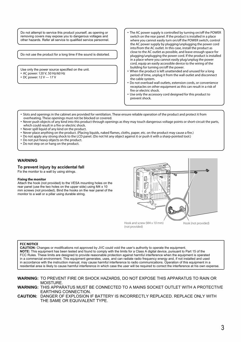
WARNINGTo prevent injury by accidental fallFix the monitor to a wall by using strings.
Fixing the monitorAttach the hook (not provided) to the VESA mounting holes on the rear panel (use the two holes on the upper side) using M4 x 10 mm screws (not provided). Bind the hooks on the rear panel of the monitor to a wall or a pillar using durable string.
Hook and screw (M4 x 10 mm) (not provided)
Hook (not provided)
DT-V9L5_EN_1.indb 3DT-V9L5_EN_1.indb 3 10/10/2012 5:18:40 PM10/10/2012 5:18:40 PM
4
Caution for use of the product for many hoursIn the case that you use the monitor for many hours, we recommend that you set “No Sync Action” in “Sync Function” to “Power Save” in Main Menu. This will reduce power consumption and relieve strain on the monitor. To reduce damage to the LCD panel, using the LCD Saver function is recommended.
Caution for use of the product in the high temperatureDo not use the product in places of high temperature; otherwise, parts of this product or the LCD panel may be damaged. This product is equipped with a temperature sensor to give warning if the temperature becomes too high. If the temperature exceeds the range of normal use, “Temp. Over” is displayed, and the power is turned off automatically if the temperature becomes any higher. In this case, move the product to a place of low temperature to let it cool down.
MaintenanceUnplug this product from the wall outlet before cleaning.
LCD panelTo avoid irreparable change in appearance of the screen such as uneven color, discoloration, scratches, be careful about the following:● Do not paste or stick anything using any glues or adhesive
tapes.● Do not write anything on the screen.● Do not strike the screen with a hard object.● Avoid condensation on the screen.● Do not wipe the screen with any liquid such as water. In
addition, wiping the screen with water-diluted neutral detergent or solvent such as alcohol, thinner, or benzine may affect the anti-reflection treatment of the screen.
● Do not wipe the screen forcefully.
Wipe stains off the LCD panel with a soft cloth. If the screen gets heavily stained, wipe it with a soft cloth soaked in water-diluted neutral detergent and wrung well, then wipe with a soft dry cloth.
CabinetTo avoid the deterioration or damages of the cabinet such as its paint’s peeling away, be careful about the following:● Do not wipe the cabinet using solvent such as alcohol, thinner,
or benzine.● Do not expose the cabinet to any volatile substance such as
insecticides.● Do not allow any rubber or plastic in contact for a long time.● Do not wipe the cabinet forcefully.
Wipe stains off the cabinet with a soft cloth. If the cabinet gets heavily stained, wipe it with a soft cloth soaked in water-diluted neutral detergent and wrung well, then wipe with a soft dry cloth.
Ventilation openingsUse a vacuum cleaner to get rid of the dust around the intakes (all the openings). If a vacuum cleaner is not available, use a cloth and wipe it off. Leaving the dust around the intakes may prevent proper temperature control and cause damage to the product.
Safety Precautions (cont.)
The LCD panel and backlight have life expectancy. Due to the basic characteristics of the LCD panel, an afterimage or uneven display may occur. It is recommended that you change images occasionally, activate the power saving function, or often turn off the power to reduce the load on the LCD panel. Continuous operations of the LCD panel may accelerate the deterioration.
Operating Precautions
IMPORTANT SAFETY INSTRUCTIONS1) Read these instructions.2) Keep these instructions.3) Heed all warnings.4) Follow all instructions.5) Do not use this apparatus near water.6) Clean only with dry cloth.7) Do not block any ventilation openings. Install in accordance with the manufacturer’s instructions.8) Do not install near any heat sources such as radiators, heat registers, stoves, or other apparatus (including amplifiers) that produce heat.9) Do not defeat the safety purpose of the polarized or grounding-type plug. A polarized plug has two blades with one wider than the other.
A grounding type plug has two blades and a third grounding prong. The wide blade or the third prong are provided for your safety. If the provided plug does not fit into your outlet, consult an electrician for replacement of the obsolete outlet.
10) Protect the power cord from being walked on or pinched particularly at plugs, convenience receptacles, and the point where they exit from the apparatus.
11) Only use attachments/accessories specified by the manufacturer.12) Use only with the cart, stand, tripod, bracket, or table specified by the manufacturer, or sold with the apparatus.
When a cart is used, use caution when moving the cart/apparatus combination to avoid injury from tip-over.13) Unplug this apparatus during lightning storms or when unused for long periods of time.14) Refer all servicing to qualified service personnel. Servicing is required when the apparatus has been damaged in any
way, such as power-supply cord or plug is damaged, liquid has been spilled or objects have fallen into the apparatus, the apparatus has been exposed to rain or moisture, does not operate normally, or has been dropped.
15) Apparatus shall not be exposed to dripping or splashing and no objects filled with liquids, such as vases, shall be placed on the apparatus.
16) Batteries shall not be exposed to excessive heat such as sunshine, fire or the like.17) When discarding batteries, environmental problems must be considered and the local rules or laws governing the disposal of these batteries
must be followed strictly.
DT-V9L5_EN_1.indb 4DT-V9L5_EN_1.indb 4 10/10/2012 5:18:40 PM10/10/2012 5:18:40 PM
5
Table of Contents
Safety Precautions . . . . . . . . . . . . . . . . . . . . . . . . . . . . . . . . . . . . . . . . . . . . . . . . . . . . . . . . . . . 2IMPORTANT SAFEGUARDS 2
Operating Precautions . . . . . . . . . . . . . . . . . . . . . . . . . . . . . . . . . . . . . . . . . . . . . . . . . . . . . . . 4Caution for use of the product for many hours 4Caution for use of the product in the high temperature 4Maintenance 4
Installation . . . . . . . . . . . . . . . . . . . . . . . . . . . . . . . . . . . . . . . . . . . . . . . . . . . . . . . . . . . . . . . . . . .6Adjusting the stand height 6Tilting the monitor 7
Index of Parts and Functions . . . . . . . . . . . . . . . . . . . . . . . . . . . . . . . . . . . . . . . . . . . . . . . . . .8Rear panel 8Front panel 10
Showing Input Signals . . . . . . . . . . . . . . . . . . . . . . . . . . . . . . . . . . . . . . . . . . . . . . . . . . . . . . 11Volume Adjustment/Audio Channel Selection 11On the Information Display 11On the Status Display 12
Menu Configuration . . . . . . . . . . . . . . . . . . . . . . . . . . . . . . . . . . . . . . . . . . . . . . . . . . . . . . . . .12First Time Installation 12The operation procedure 12Menu Transition Diagram 13Main Menu 14Set-Up Menu 18
External Control . . . . . . . . . . . . . . . . . . . . . . . . . . . . . . . . . . . . . . . . . . . . . . . . . . . . . . . . . . . . 23About the external control 23Using the MAKE/TRIGGER system 23Using the serial communication 24
Troubleshooting. . . . . . . . . . . . . . . . . . . . . . . . . . . . . . . . . . . . . . . . . . . . . . . . . . . . . . . . . . . . 26Self-check program 27
Specifications . . . . . . . . . . . . . . . . . . . . . . . . . . . . . . . . . . . . . . . . . . . . . . . . . . . . . . . . . . . . . . 28General 28LCD panel 28Input/output terminals 28Dimensions 29Available signals 30
DT-V9L5_EN_1.indb 5DT-V9L5_EN_1.indb 5 10/10/2012 5:18:42 PM10/10/2012 5:18:42 PM
6
Installation
● Do not rest your arm on the monitor or lean against the monitor.● Do not touch the LCD panel when installing the monitor.● Be sure to install the monitor securely to prevent the monitor from falling over, which may cause damage to the monitor or injury.
Caution
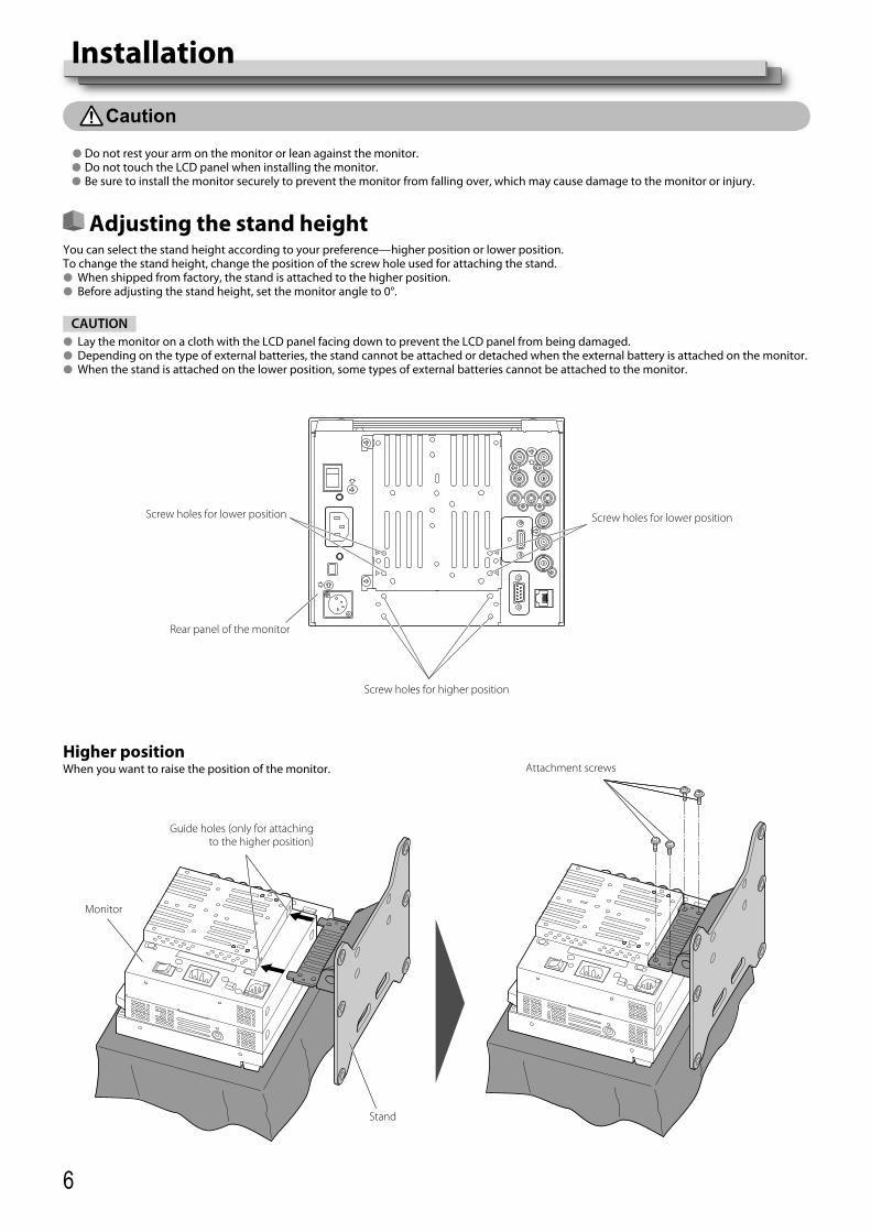
Adjusting the stand heightYou can select the stand height according to your preference—higher position or lower position.To change the stand height, change the position of the screw hole used for attaching the stand.● When shipped from factory, the stand is attached to the higher position.● Before adjusting the stand height, set the monitor angle to 0°.
CAUTION● Lay the monitor on a cloth with the LCD panel facing down to prevent the LCD panel from being damaged.● Depending on the type of external batteries, the stand cannot be attached or detached when the external battery is attached on the monitor.● When the stand is attached on the lower position, some types of external batteries cannot be attached to the monitor.
Screw holes for lower position
Guide holes (only for attaching to the higher position)
Screw holes for higher position
Rear panel of the monitor
Monitor
Attachment screws
Stand
Screw holes for lower position
Higher positionWhen you want to raise the position of the monitor.
DT-V9L5_EN_1.indb 6DT-V9L5_EN_1.indb 6 10/10/2012 5:18:42 PM10/10/2012 5:18:42 PM

7
Lower positionWhen you want to lower the position of the monitor.
Attachment screws
Monitor
Stand
Tilting the monitorYou can tilt the monitor as shown below.
About 20°
0°
About 10°
Guidelines
When the monitor is not tilted (0°), the guidelines align as illustrated.
CAUTION● Be careful not to pinch your fingers in the gap between the monitor and the stand.● When the stand is attached to the lower position, you cannot tilt the monitor downward.● Be sure to install the monitor securely to prevent the monitor from falling over, which may cause damage to the monitor or injury.
DT-V9L5_EN_1.indb 7DT-V9L5_EN_1.indb 7 10/10/2012 5:18:43 PM10/10/2012 5:18:43 PM

8
1 POWER switchTurns AC power on or off.● You need to press button (☞ q on page 10) to use the monitor after turning on the POWER switch.
2 AC IN terminalAC power input connector.Connect the provided AC power cord to an AC outlet.● Attach the provided power cord holder to prevent accidental disconnection of the AC power cord. (☞ “Attaching the power cord holder”
on page 9)CAUTION
Do not connect the power cord until all other connections are completed.3 DC switch
Turns the DC power on or off.● You need to press button (☞ q on page 10) on the front panel to turn on the monitor after turning on the DC switch.● The monitor consumes the battery even while the monitor is on standby. To save battery life, turn off the DC switch.
4 DC IN terminalDC 12 V (maximum DC 17 V) power input connector.
● While using both the AC and DC power supply, AC power supply is preferentially used. If the AC power supply is cut off (for example, when turning off the POWER switch), the power supply automatically switches to the DC power supply.
● Use a DC power supply with the LPS (Limited Power Sources) function.5 VIDEO/COMPONENT terminals (BNC)
IN: Input terminals for the composite (VBS) and the analog component (Y/PB/PR) signals. Select the signal type in “Video/Component Select” corresponding to the type of the input signal. (☞ page 15)OUT: Output terminal for the composite (VBS) and the analog component (Y) signals.
6 AUDIO (IN) terminal (pin jack)Input terminal for the analog audio signals.● Use this terminal for the analog audio connection of the SDI. To select the audio output, set in “Audio Setting” of the Main Menu.● When you use HDMI input for the picture and analog sound for the audio signal, input analog sound into this terminal, and set in “Audio
Setting” of the Main Menu. (☞ page 16)
Rear panel
Index of Parts and Functions
Security slotAttach a security wire to this slot.
When using DC 12 V power (maximum DC 17 V), check the DC IN terminal pin signal, and use the correct polarity. If the polarity is reversed, this could cause a fire or personal injury.
Carry handleUse this handle when carrying the monitor.
DT-V9L5_EN_1.indb 8DT-V9L5_EN_1.indb 8 10/10/2012 5:18:43 PM10/10/2012 5:18:43 PM

9
7 HDMI terminalInput terminal compatible with HDCP for the HDMI signal. (TYPE-A)
8 REMOTE terminalTerminal for controlling the monitor by an external control. (☞ “External Control” on page 23)
9 AUDIO (MONITOR OUT) terminals (pin jack)Output terminals for the analog audio signal.● The terminals emit the audio signals through the AUDIO (IN) terminal or EMBEDDED AUDIO signals through the E. AUDIO HD/SD SDI (IN 1
or IN 2) input terminal.● The signal is output from this terminal only when the monitor is on or in “Power Save” (power save) mode (☞ “No Sync Action” on page 18).● The EMBEDDED AUDIO signal...
is decoded into an analog signal, then emitted. –is emitted only when “SDI 1” or “SDI 2” is selected, and when EMBEDDED AUDIO signals come in to the E. AUDIO HD/SD SDI (IN 1 or IN 2) –terminal.
● Audio signals are only output from the HDMI terminal when the signals are not protected by HDCP.Even when the signals are protected by HDCP, sound is emitted from the speakers. –
p E. AUDIO HD/SD SDI (IN 1, IN 2) terminals (BNC)Input terminals for the HD/SD SDI signals.● The terminals accept also EMBEDDED AUDIO signals including up to 16 audio channels with a sampling frequency of 48 kHz.
q E. AUDIO HD/SD SDI (SWITCHED OUT) terminal (BNC)Output terminal for the HD/SD SDI signals.● The SDI signals of the current input (SDI 1 or SDI 2) are re-clocked, then emitted.● When an input other than SDI 1 and SDI 2 is selected, the SDI signal of the input selected last time is emitted from this terminal.● The signals are emitted from this terminal only when the monitor is on or in “Power Save” (power save) mode (☞ “No Sync Action” on
page 18).w Screw holes for external battery attachment
Attach external battery for DC power supply by using 2 screw holes. Choose the appropriate screw holes from 1, 2 or 3 according to the type of external battery. (Depending on the battery type.)Use the Anton Bauer Dionic 90 (mount: QR DXC-M3A) external battery.
CAUTION● Do not use the external battery for DC 24 V power supply.● Use only the battery specified above. If a heavy battery is used, it may fall off depending on the way the monitor is used.
Cover
2
AC IN terminal
Case1
CAUTION● Use only the provided screws.● Make sure the plug will not be pulled out after the cover is attached to the case.
Attaching the power cord holderThe provided power cord holder prevents accidental disconnection of the AC power cord from the AC IN terminal.● The power cord holder consists of two parts, a case and a cover.
To detach the cover3
Note for connectionsBefore making any connections, turn off all the equipment.• Use a cord whose plugs correctly match the terminals on this monitor and the equipment.• Plugs should be firmly inserted; poor connections could cause noise.• When unplugging a cord, be sure to grasp its plug and pull it out.• DO NOT connect the power cord until all connections are complete.• Refer also to the user manual of each piece of equipment.•
DT-V9L5_EN_1.indb 9DT-V9L5_EN_1.indb 9 10/10/2012 5:18:44 PM10/10/2012 5:18:44 PM
10
Front panel
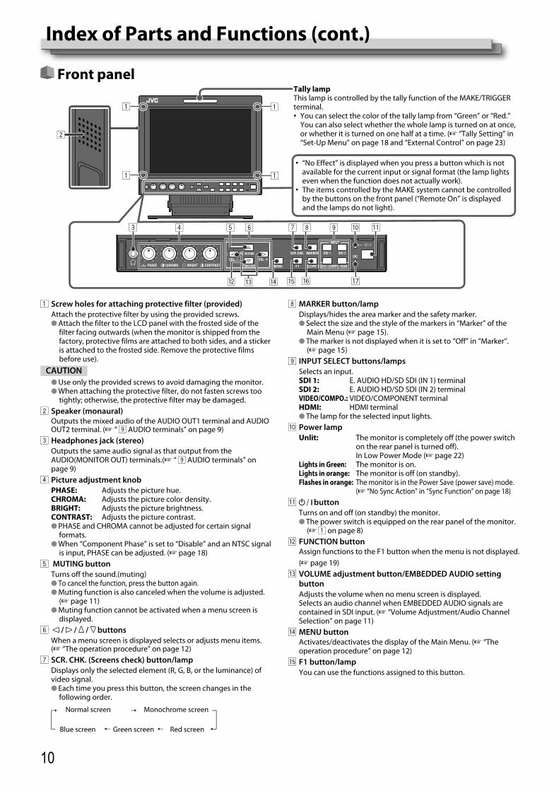
1 Screw holes for attaching protective filter (provided)Attach the protective filter by using the provided screws.● Attach the filter to the LCD panel with the frosted side of the
filter facing outwards (when the monitor is shipped from the factory, protective films are attached to both sides, and a sticker is attached to the frosted side. Remove the protective films before use).
CAUTION● Use only the provided screws to avoid damaging the monitor.● When attaching the protective filter, do not fasten screws too
tightly; otherwise, the protective filter may be damaged.2 Speaker (monaural)
Outputs the mixed audio of the AUDIO OUT1 terminal and AUDIO OUT2 terminal. (☞ “ 9 AUDIO terminals” on page 9)
3 Headphones jack (stereo)Outputs the same audio signal as that output from the AUDIO(MONITOR OUT) terminals.(☞ “ 9 AUDIO terminals” on page 9)
4 Picture adjustment knobPHASE: Adjusts the picture hue.CHROMA: Adjusts the picture color density.BRIGHT: Adjusts the picture brightness.CONTRAST: Adjusts the picture contrast.● PHASE and CHROMA cannot be adjusted for certain signal
formats.● When “Component Phase” is set to “Disable” and an NTSC signal
is input, PHASE can be adjusted. (☞ page 18)5 MUTING button
Turns off the sound.(muting)● To cancel the function, press the button again.● Muting function is also canceled when the volume is adjusted.
(☞ page 11)● Muting function cannot be activated when a menu screen is
displayed.6 / / / buttons
When a menu screen is displayed selects or adjusts menu items. (☞ “The operation procedure” on page 12)
7 SCR. CHK. (Screens check) button/lampDisplays only the selected element (R, G, B, or the luminance) of video signal.● Each time you press this button, the screen changes in the
following order.
Normal screen
Red screenGreen screenBlue screen
Monochrome screen
Index of Parts and Functions (cont.)
“No Effect” is displayed when you press a button which is not • available for the current input or signal format (the lamp lights even when the function does not actually work).The items controlled by the MAKE system cannot be controlled • by the buttons on the front panel (“Remote On” is displayed and the lamps do not light).
Tally lampThis lamp is controlled by the tally function of the MAKE/TRIGGER terminal.
You can select the color of the tally lamp from “Green” or “Red.” • You can also select whether the whole lamp is turned on at once, or whether it is turned on one half at a time. (☞ “Tally Setting” in “Set-Up Menu” on page 18 and “External Control” on page 23)
8 MARKER button/lampDisplays/hides the area marker and the safety marker.● Select the size and the style of the markers in “Marker” of the
Main Menu (☞ page 15).● The marker is not displayed when it is set to “Off” in “Marker”.
(☞ page 15)9 INPUT SELECT buttons/lamps
Selects an input.SDI 1: E. AUDIO HD/SD SDI (IN 1) terminalSDI 2: E. AUDIO HD/SD SDI (IN 2) terminalVIDEO/COMPO.: VIDEO/COMPONENT terminalHDMI: HDMI terminal● The lamp for the selected input lights.
p Power lampUnlit: The monitor is completely off (the power switch
on the rear panel is turned off). In Low Power Mode (☞ page 22)Lights in Green: The monitor is on.Lights in orange: The monitor is off (on standby).Flashes in orange: The monitor is in the Power Save (power save) mode.
(☞ “No Sync Action” in “Sync Function” on page 18)q button
Turns on and off (on standby) the monitor.● The power switch is equipped on the rear panel of the monitor.
(☞ 1 on page 8)w FUNCTION button
Assign functions to the F1 button when the menu is not displayed. (☞ page 19)
e VOLUME adjustment button/EMBEDDED AUDIO setting buttonAdjusts the volume when no menu screen is displayed.Selects an audio channel when EMBEDDED AUDIO signals are contained in SDI input. (☞ “Volume Adjustment/Audio Channel Selection” on page 11)
r MENU buttonActivates/deactivates the display of the Main Menu. (☞ “The operation procedure” on page 12)
t F1 button/lampYou can use the functions assigned to this button.
HDMISCOPE
INPUT
DT-V9L5_EN_1.indb 10DT-V9L5_EN_1.indb 10 10/10/2012 5:18:44 PM10/10/2012 5:18:44 PM
11
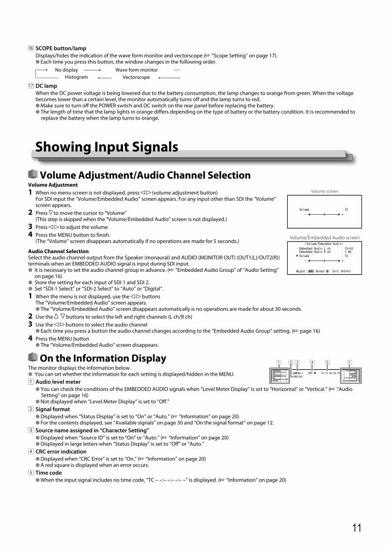
Volume Adjustment/Audio Channel SelectionVolume Adjustment1 When no menu screen is not displayed, press (volume adjustment button)
For SDI input the “Volume/Embedded Audio” screen appears. For any input other than SDI the “Volume” screen appears.
2 Press to move the cursor to “Volume”(This step is skipped when the ”Volume/Embedded Audio” screen is not displayed.)
3 Press to adjust the volume4 Press the MENU button to finish
(The “Volume” screen disappears automatically if no operations are made for 5 seconds.)
Audio Channel SelectionSelect the audio channel output from the Speaker (monaural) and AUDIO (MONITOR OUT) (OUT1(L)/OUT2(R)) terminals when an EMBEDDED AUDIO signal is input during SDI input.● It is necessary to set the audio channel group in advance. (☞ ”Embedded Audio Group” of “Audio Setting”
on page 16)● Store the setting for each input of SDI 1 and SDI 2.● Set “SDI-1 Select” or “SDI-2 Select” to “Auto” or “Digital”.1 When the menu is not displayed, use the buttons
The “Volume/Embedded Audio” screen appears.● The “Volume/Embedded Audio” screen disappears automatically is no operations are made for about 30 seconds.
2 Use the buttons to select the left and right channels (L ch/R ch)3 Use the buttons to select the audio channel
● Each time you press a button the audio channel changes according to the “Embedded Audio Group” setting. (☞ page 16)4 Press the MENU button
● The “Volume/Embedded Audio” screen disappears.
On the Information DisplayThe monitor displays the information below.● You can set whether the information for each setting is displayed/hidden in the MENU.1 Audio level meter
● You can check the conditions of the EMBEDDED AUDIO signals when “Level Meter Display” is set to “Horizontal” or “Vertical.” (☞ “Audio Setting” on page 16)
● Not displayed when “Level Meter Display” is set to “Off.”2 Signal format
● Displayed when “Status Display” is set to “On” or “Auto.” (☞ “Information” on page 20)● For the contents displayed, see “Available signals” on page 30 and “On the signal format” on page 12.
3 Source name assigned in “Character Setting”● Displayed when “Source ID” is set to “On” or “Auto.” (☞ “Information” on page 20)● Displayed in large letters when “Status Display” is set to “Off” or “Auto.”
4 CRC error indication● Displayed when “CRC Error” is set to “On.” (☞ “Information” on page 20)● A red square is displayed when an error occurs.
5 Time code● When the input signal includes no time code, “TC – –:– –:– –:– –” is displayed. (☞ “Information” on page 20)
y SCOPE button/lampDisplays/hides the indication of the wave form monitor and vectorscope (☞ “Scope Setting” on page 17).● Each time you press this button, the window changes in the following order.
Wave form monitorVectorscope
No display
u DC lampWhen the DC power voltage is being lowered due to the battery consumption, the lamp changes to orange from green. When the voltage becomes lower than a certain level, the monitor automatically turns off and the lamp turns to red.● Make sure to turn off the POWER switch and DC switch on the rear panel before replacing the battery.● The length of time that the lamp lights in orange differs depending on the type of battery or the battery condition. It is recommended to
replace the battery when the lamp turns to orange.
Volume screen
Volume/Embedded Audio screen
Showing Input Signals
Histogram
DT-V9L5_EN_1.indb 11DT-V9L5_EN_1.indb 11 10/10/2012 5:18:46 PM10/10/2012 5:18:46 PM
12
First Time InstallationWhen you turn on the power and the monitor, “First Time Installation” appears.Start setting referring to the menu configuration.
For the setting items, see the pages below.“Language” • ☞ “Language” on page 20“No Sync Action” • ☞ “Sync Function” on page 18“No Operation Action” • ☞ “No Operation Action” on page 18
Setting procedure1 Press to move the cursor to the setting item2 Press to select the setting values
● Each time you press one of these buttons, the setting value changes.3 Move the cursor to “Set”4 Press to finish setting
● When you change the settings, a confirmation message appears.Operate according to directions.
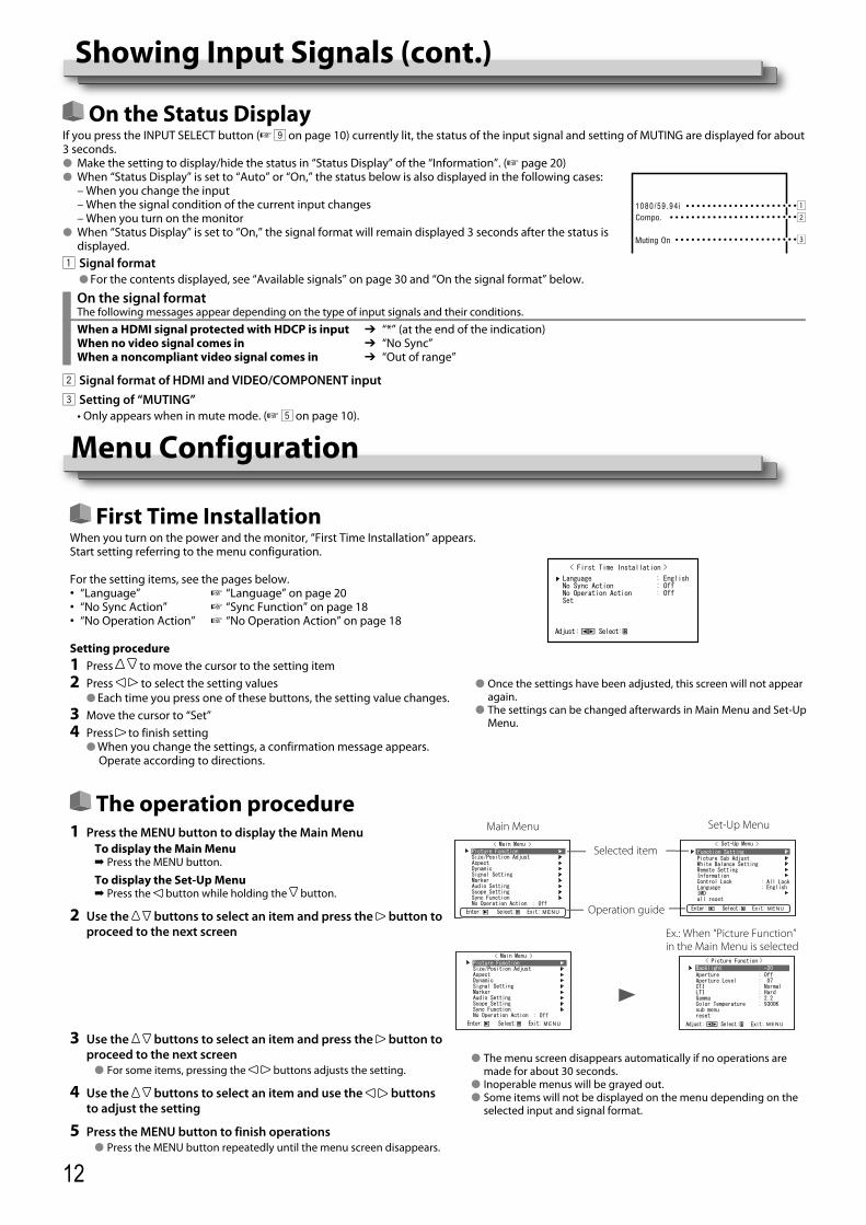
The operation procedure1 Press the MENU button to display the Main Menu
To display the Main Menu➡ Press the MENU button.
To display the Set-Up Menu➡ Press the button while holding the button.
2 Use the buttons to select an item and press the button to proceed to the next screen
3 Use the buttons to select an item and press the button to proceed to the next screen
● For some items, pressing the buttons adjusts the setting.
4 Use the buttons to select an item and use the buttons to adjust the setting
5 Press the MENU button to finish operations● Press the MENU button repeatedly until the menu screen disappears.
On the Status DisplayIf you press the INPUT SELECT button (☞ 9 on page 10) currently lit, the status of the input signal and setting of MUTING are displayed for about 3 seconds.● Make the setting to display/hide the status in “Status Display” of the “Information”. (☞ page 20)● When “Status Display” is set to “Auto” or “On,” the status below is also displayed in the following cases: – When you change the input – When the signal condition of the current input changes – When you turn on the monitor● When “Status Display” is set to “On,” the signal format will remain displayed 3 seconds after the status is
displayed.1 Signal format
● For the contents displayed, see “Available signals” on page 30 and “On the signal format” below.
On the signal formatThe following messages appear depending on the type of input signals and their conditions.
When a HDMI signal protected with HDCP is inputWhen no video signal comes inWhen a noncompliant video signal comes in
“*” (at the end of the indication) ➔“No Sync” ➔“Out of range” ➔
2 Signal format of HDMI and VIDEO/COMPONENT input3 Setting of “MUTING” • Only appears when in mute mode. (☞ 5 on page 10).
Showing Input Signals (cont.)
Main Menu
Selected item
Operation guide
Set-Up Menu
Ex.: When “Picture Function” in the Main Menu is selected
Menu Configuration
● The menu screen disappears automatically if no operations are made for about 30 seconds.
● Inoperable menus will be grayed out.● Some items will not be displayed on the menu depending on the
selected input and signal format.
● Once the settings have been adjusted, this screen will not appear again.
● The settings can be changed afterwards in Main Menu and Set-Up Menu.
DT-V9L5_EN_1.indb 12DT-V9L5_EN_1.indb 12 10/10/2012 5:18:47 PM10/10/2012 5:18:47 PM

13
Menu Transition DiagramMain Menu
Picture Function
Audio Setting
Sync Function
No Operation Action
Signal Setting
Marker
Aspect
BacklightApertureAperture LevelCTILTIGammaColor Temperaturesub menureset
Level Meter DisplayChannel ArrangePositionMeter TypeReference LevelOver LevelTransparentPeak Hold
H SizeH PositionV SizeV Postionsub menureset
Video/Component SelectI/P ModeColor Systemsub menureset
Area MarkerMarker AspectSafety MarkerSafety AreaFrameCenter MarkerLine BrightnessR-Area MarkerR-Marker AspectR-Safety MarkerR-Safety Area
Auto AspectManual AspectSD4:3 Size16:9 Size1:1
SDI-1 SelectSDI-2 SelectHDMI SelectVideo/Component SelectEmbedded Audio GroupLevel Meter Setting
No Sync ActionDelay TimeLow Latency
Size/Position Adjust
Dynamic
Scope Setting
GainSizePositionTransparentAuto OffHistogram DisplayWave DisplayWave FilterWave Over Level MarkingWave Over Level
Set-Up Menu
ContrastBrightChromaPhaseNTSC SetupComponent Levelsub menureset
Color Temperature*R DriveG DriveB DriveR Cut OffG Cut OffB Cut Offsub menureset
Function Setting
Picture Sub Adjust
White Balance Setting
Remote Setting
Information
Control Lock
Language
IMD
all reset
sub menu PositionTally SettingDimmerComponent PhaseRemote Active On StandbyLCD SaverFunction Key Setting
SettingExecuteCancelStatusStart After
Tally TypeTally Color
1st StartWork TimeContrastBacklightOSD ContrastSide Maskreset
Parallel TypePin1Pin2Pin3Pin4Pin5Pin6Pin7Pin8
Source IDCharacter SettingStatus DisplayTime CodeTime Code SelectCRC ErrorSub Hour MeterModelVersionHour Meter
IMD DisplayIMD ProtocolAddressIMD SizeText ColorTally 1 ColorTally 2 ColorBackground Colorreset
Function 1Function Display
* : "Color Temperature" is only displayed, and cannot be set/changed.
DT-V9L5_EN_1.indb 13DT-V9L5_EN_1.indb 13 10/10/2012 5:18:49 PM10/10/2012 5:18:49 PM
14
Menu Configuration (cont.)
Main Menu
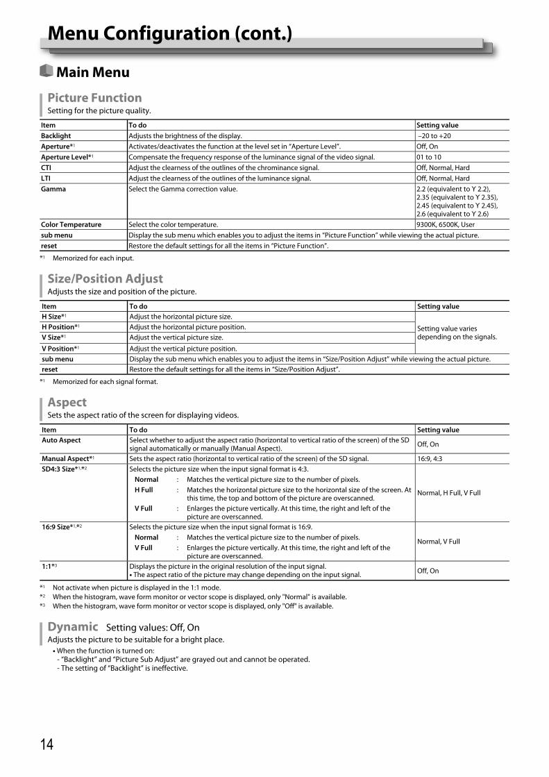
Picture FunctionSetting for the picture quality.
Item To do Setting valueBacklight Adjusts the brightness of the display. –20 to +20Aperture*1 Activates/deactivates the function at the level set in “Aperture Level”. Off, OnAperture Level*1 Compensate the frequency response of the luminance signal of the video signal. 01 to 10CTI Adjust the clearness of the outlines of the chrominance signal. Off, Normal, HardLTI Adjust the clearness of the outlines of the luminance signal. Off, Normal, HardGamma Select the Gamma correction value. 2.2 (equivalent to Υ 2.2),
2.35 (equivalent to Υ 2.35), 2.45 (equivalent to Υ 2.45), 2.6 (equivalent to Υ 2.6)
Color Temperature Select the color temperature. 9300K, 6500K, Usersub menu Display the sub menu which enables you to adjust the items in “Picture Function” while viewing the actual picture.reset Restore the default settings for all the items in “Picture Function”.
*1 Memorized for each input.
Size/Position AdjustAdjusts the size and position of the picture.
Item To do Setting valueH Size*1 Adjust the horizontal picture size.
Setting value varies depending on the signals.
H Position*1 Adjust the horizontal picture position.V Size*1 Adjust the vertical picture size.
V Position*1 Adjust the vertical picture position.sub menu Display the sub menu which enables you to adjust the items in “Size/Position Adjust” while viewing the actual picture.reset Restore the default settings for all the items in “Size/Position Adjust”.
*1 Memorized for each signal format.
AspectSets the aspect ratio of the screen for displaying videos.
Item To do Setting valueAuto Aspect Select whether to adjust the aspect ratio (horizontal to vertical ratio of the screen) of the SD
signal automatically or manually (Manual Aspect). Off, On
Manual Aspect*1 Sets the aspect ratio (horizontal to vertical ratio of the screen) of the SD signal. 16:9, 4:3 SD4:3 Size*1,*2 Selects the picture size when the input signal format is 4:3.
Normal, H Full, V Full
Normal : Matches the vertical picture size to the number of pixels.H Full : Matches the horizontal picture size to the horizontal size of the screen. At
this time, the top and bottom of the picture are overscanned.V Full : Enlarges the picture vertically. At this time, the right and left of the
picture are overscanned.16:9 Size*1,*2 Selects the picture size when the input signal format is 16:9.
Normal, V FullNormal : Matches the vertical picture size to the number of pixels.V Full : Enlarges the picture vertically. At this time, the right and left of the
picture are overscanned.1:1*3 Displays the picture in the original resolution of the input signal.
• The aspect ratio of the picture may change depending on the input signal. Off, On
*1 Not activate when picture is displayed in the 1:1 mode.*2 When the histogram, wave form monitor or vector scope is displayed, only "Normal" is available.*3 When the histogram, wave form monitor or vector scope is displayed, only "Off" is available.
Dynamic Setting values: Off, OnAdjusts the picture to be suitable for a bright place.
• When the function is turned on: - “Backlight” and “Picture Sub Adjust” are grayed out and cannot be operated. - The setting of “Backlight” is ineffective.
DT-V9L5_EN_1.indb 14DT-V9L5_EN_1.indb 14 10/10/2012 5:18:49 PM10/10/2012 5:18:49 PM

15
Signal SettingSettings for input signals.
Item To do Setting valueVideo/Component Select Selects the signal type you want to use for VIDEO/COMPONENT terminals. Video, ComponentI/P Mode Selects a proper mode corresponding to the input picture. Normal, CinemaColor System Select the color system. Auto, NTSC, PAL, SECAM,
NTSC 4.43, PAL-M, PAL-N, PAL60
• If the picture is unstable with “Auto,” select the color system according to the input signal.
sub menu Display the sub menu which enables you to adjust the items in “Signal Setting” while viewing the actual picture.reset Restore the default settings for all the items in “Signal Setting”.
Marker*1
Settings for marker functions.
Item To do Setting value1/2 Area Marker Activate/deactivate the area marker and select the style of it.
The setting values and features are as follows.Off, Line, Half, Half+Line
OffLineHalf
Half+Line
:::
:
Deactivate the marker.Displays the area with an outline.The area outside the specified aspect ratio of the screen is displayed at 50% transparency.The area of the specified aspect ratio of the screen is indicated by an outline, and the area outside of that is displayed at 50% transparency.
Marker Aspect Select the aspect ratio of the area marker. 4:3, 16:9, 14:9, 13:9, 2.35:1, 1.85:1, 1.75:1, 1.66:1
Safety Marker Activate/deactivate the safety marker and select the style of it.*2 Off, Line, Half, Half+LineSafety Area Adjust the area of the safety marker. 80% to 100%Frame*3 Displays/Hides the video area. Off, On
Center Marker*3 Displays/hides the marker indicating the center position of the picture. Off, OnLine Brightness Adjust the brightness of the marker. Low, High
2/2 R-Area Marker Activate/deactivate the area marker and select the style of it.*2 Off, Line, Half, Half+LineR-Marker Aspect Select the aspect ratio of the area marker. 4:3, 16:9, 14:9, 13:9, 2.35:1,
1.85:1, 1.75:1, 1.66:1R-Safety Marker Activate/deactivate the safety marker and select the style of it.*2 Off, Line, Half, Half+LineR-Safety Area Adjust the area of the safety marker. 80% to 100%
● The area marker or the safety marker is displayed by using MARKER button or external control.● “R” means “REMOTE (External control)”. Select either non-“R-” items or “R-” items to activate by using external control. (☞ “External Control” on
page 23)● When a picture is displayed in 4:3 aspect ratio, the safety marker for the 4:3 area is displayed.● To display the safety marker for the area of a picture displayed in 16:9 aspect ratio, set Area Marker to "Off".*1 Memorized for each signal format.*2 The setting values are the same as that of “Area Marker”.*3 In 1:1 mode, this display is grayed out and cannot be operated.
DT-V9L5_EN_1.indb 15DT-V9L5_EN_1.indb 15 10/10/2012 5:18:50 PM10/10/2012 5:18:50 PM

16
Menu Configuration (cont.)
Audio SettingSettings for EMBEDDED AUDIO signals and audio level meter signal.
Item To do Setting valueSDI-1 SelectSDI-2 Select
Select the input through which audio is output. Off, Auto, Digital, Analog
OffAutoDigitalAnalog
::::
Does not output audio.Output digital audio prior to analog audio.Output audio from the SDI terminal.Output audio from the AUDIO IN terminal.
HDMI Select Select the input through which audio is output. Off, Digital, AnalogOffDigitalAnalog
:::
Does not output audio.Output audio from the HDMI terminal.Output audio from the AUDIO IN terminal.
Video/Component Select Select the input through which audio is output. Off, AnalogOffAnalog
::
Does not output audio.Output audio from the AUDIO IN terminal.
Embedded Audio Group*1 Select the audio channel group of the EMBEDDED AUDIO signals.The setting values and selectable audio channels of EMBEDDED AUDIO signals are as follows. (G means GROUP)
1G, 2G, 1-2G ,3G, 4G, 1-4G, 3-4G
1G2G1-2G
3G4G1-4G
3-4G
:::
:::
:
channel(s) 1/2/3/4/1+2/3+4/1 – 4 (1G)channel(s) 5/6/7/8/5+6/7+8/5 – 8 (2G)channel(s) 1/2/3/4/5/6/7/8/1+2/3+4/5+6/7+8/1 – 4 (1G)/5 – 8 (2G)/1 – 8 (1G+2G)channel(s) 9/10/11/12/9+10/11+12/9 – 12 (3G)channel(s) 13/14/15/16/13+14/15+16/13 - 16(4G)channel(s) 1/2/3/4/5/6/7/8/9/10/11/12/13/14/15/16/1+2/3+4/5+6/7+8/9+10/11+12/13+14/15+16/1–4(1G)/5–8(2G)/9–12(3G)/13-16(4G)/1–8(1G+2G)/1-16(1-4G)channel(s) 9/10/11/12/13/14/15/16/9+10/11+12/13+14/15+16/9 –12 (3G)/13-16(4G)/9-16(3-4G)
Level Meter Setting*1 Specify the audio level meter display for EMBEDDED AUDIO signal.Example of audio level meter display - Connection between the level meter position and channelEx: When “Horizontal” is selected for “Level Meter Display”: Ex: When “Vertical” is selected for “Level Meter Display”:
-10dB -20dB-20dB -10dB
-20dB
-10dB
-20dB
-10dB
• The number of audio channels displayed on the level meter varies depending on the setting value of “Embedded Audio Group”.
• The audio level meter can be displayed at the top or bottom of the screen.• When “On” is selected for “Peak Hold”, the maximum value is retained a certain period when the signal level becomes
maximum.Level Meter Display Select the status of the level meter (display vertically, horizontally, or not displayed). Off, Vertical, HorizontalChannel Arrange Select how the audio channels are displayed on the level meter. Line, DividePosition Adjust the vertical level meter position. Upper, LowerMeter Type Specify the design of the level meter. Bar, BlockReference Level Select the standard input level indicated on the level meter. –20dB, –18dBOver Level Select the input level’s lower limit indicated in red. –10dB, –8dB, –6dB, –4dB,
–2dBTransparent Adjust the transparency of the level meter display against the image. Off, Background, AllPeak Hold Activates/deactivates the peak hold function of the level meter. Off, On
*1 Memorized for each input.
Green
REFERENCE LEVEL
OVER LEVEL
RedYellow
OVER LEVEL
REFERENCE LEVEL
DT-V9L5_EN_1.indb 16DT-V9L5_EN_1.indb 16 10/10/2012 5:18:51 PM10/10/2012 5:18:51 PM
17
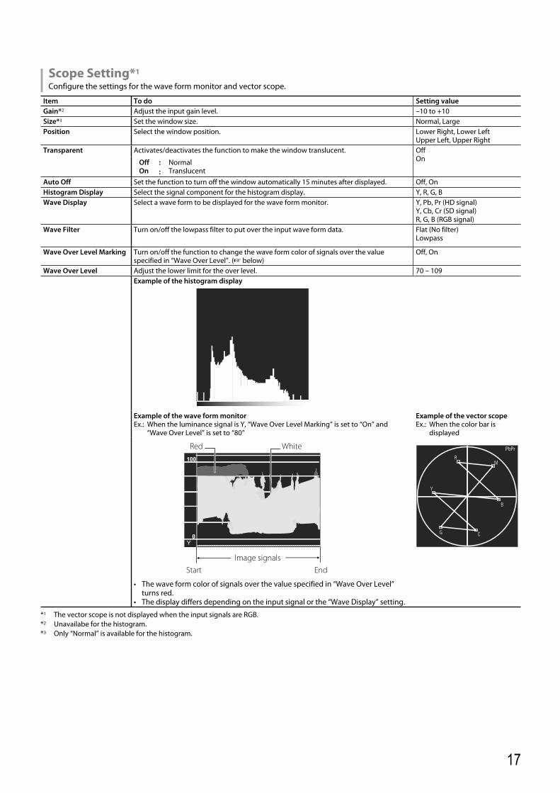
Scope Setting*1
Configure the settings for the wave form monitor and vector scope.
Item To do Setting valueGain*2 Adjust the input gain level. –10 to +10Size*3 Set the window size. Normal, LargePosition Select the window position. Lower Right, Lower Left
Upper Left, Upper RightTransparent Activates/deactivates the function to make the window translucent. Off
OnOffOn
::
NormalTranslucent
Auto Off Set the function to turn off the window automatically 15 minutes after displayed. Off, OnHistogram Display Select the signal component for the histogram display. Y, R, G, BWave Display Select a wave form to be displayed for the wave form monitor. Y, Pb, Pr (HD signal)
Y, Cb, Cr (SD signal)R, G, B (RGB signal)
Wave Filter Turn on/off the lowpass filter to put over the input wave form data. Flat (No filter)Lowpass
Wave Over Level Marking Turn on/off the function to change the wave form color of signals over the value specified in “Wave Over Level”. (☞ below)
Off, On
Wave Over Level Adjust the lower limit for the over level. 70 – 109Example of the histogram display
Example of the wave form monitorEx.: When the luminance signal is Y, “Wave Over Level Marking” is set to “On” and
“Wave Over Level” is set to “80”
Example of the vector scopeEx.: When the color bar is
displayed
• The wave form color of signals over the value specified in “Wave Over Level” turns red.
• The display differs depending on the input signal or the “Wave Display” setting.
*1 The vector scope is not displayed when the input signals are RGB.*2 Unavailabe for the histogram.*3 Only “Normal” is available for the histogram.
Start End
Red White
Y
Image signals
DT-V9L5_EN_1.indb 17DT-V9L5_EN_1.indb 17 10/10/2012 5:18:51 PM10/10/2012 5:18:51 PM

18
Menu Configuration (cont.)
Sync FunctionSettings for the synchronization with signals.
Item To do Setting valueNo Sync Action Select the screen status when no signal is coming in. Off, Standby, Power Save
(power save mode), Gray Back (gray screen)
Delay Time Select the period until the screen status changes as selected in “No Sync Action” after signals stop coming in.
30s, 5min, 15min
Low Latency Activates/deactivates the function to shorten the time taken to display the picture (low latency function).
Off, On
• If the picture is not displayed steadily while “On” is selected, select “Off.”• While “On” is selected, the displayed picture may become unstable when an operation
using buttons on the front panel or the menu is performed, or when the signal format changes.
● When setting “No Sync Action” to “Gray Back,” the screen color changes to gray and the power consumption of the backlight is saved by half. Selecting “Power Save” (power save mode) saves more power consumption by turning off the backlight.
No Operation Action Setting values: Off, OnSetting of the function for turning the unit off (standby) automatically when no operations are made for more than 4 hours.Off: Does not turn off automaticallyOn: Turns off automatically● When the function is turned On, a warning message will be displayed about 3 minutes before turning off automatically.
When you turn on the unit with the function turned On, a message notifying that the setting is turned on will be displayed for about 30 seconds.
Set-Up MenuFunction Setting Settings for the sub menu display, color of the tally lamp, and the intensity of the button lamps.
Item To do Setting valuesub menu Position Select the contents and displaying position of “sub menu.”
The setting values and features are as follows.Lower1, Upper1, Lower2, Upper2
Lower1 : Displays the current setting and adjustment bar at the lower part of the screen.Upper1 : Displays the current setting and adjustment bar at the upper part of the screen.Lower2 : Displays the current setting at the lower part of the screen.Upper2 : Displays the current setting at the upper part of the screen.
• The adjustment bar is not displayed for some items.Tally Setting Set the color and mode of the tally lamp using external control.
Tally Type NormalHalf
::
Light up the entire tally.Light up the left and right halves of the tally individually. Normal, Half
Tally Color Set the tally color when “Tally Type” is set to “Normal”. Green, RedDimmer Select the intensity of the button lamps. Normal, DarkComponent Phase Deactivates the function of PHASE adjustment (Picture adjustment knob and “Picture Sub
Adjust” in Set-Up Menu) except when an NTSC signal comes in (☞ on page 19).Enable, Disable
Remote Active On Standby
Set the conditions for the power switch by external control (serial). Off, OnOffOn
::
Cannot power on by external control after powered OFF.Can power on by external control after powered OFF.
LCD Saver Configure the setting for reducing damage to the LCD panel for long-time use. (☞ on page 22)Setting 1st Start Set the standby time. (unit: hours) 00h-24h
Work Time
Set the time for performing the function. (unit: hours) 01h-06h
Contrast Set the contrast reduction. Normal, SaveBacklight Reduce the backlight brightness. Normal, SaveOSD Contrast
Set the contrast reduction of the OSD display. Normal, Save
Side Mask Select whether to use the side panel.* The Side Mask function works no matter whether the LCD Saver is active or stopped. Off, On
reset Restore the default settings for all the items in “LCD Saver”.Execute Execute the LCD Saver function.Cancel Stop the LCD Saver function. (“Cancel” will be grayed out during the function stop.)Status Display the LCD Saver status. Off, ReadyStart After Stop the LCD Saver function. (unit: hours and minutes) **h **min
DT-V9L5_EN_1.indb 18DT-V9L5_EN_1.indb 18 10/10/2012 5:18:52 PM10/10/2012 5:18:52 PM
19
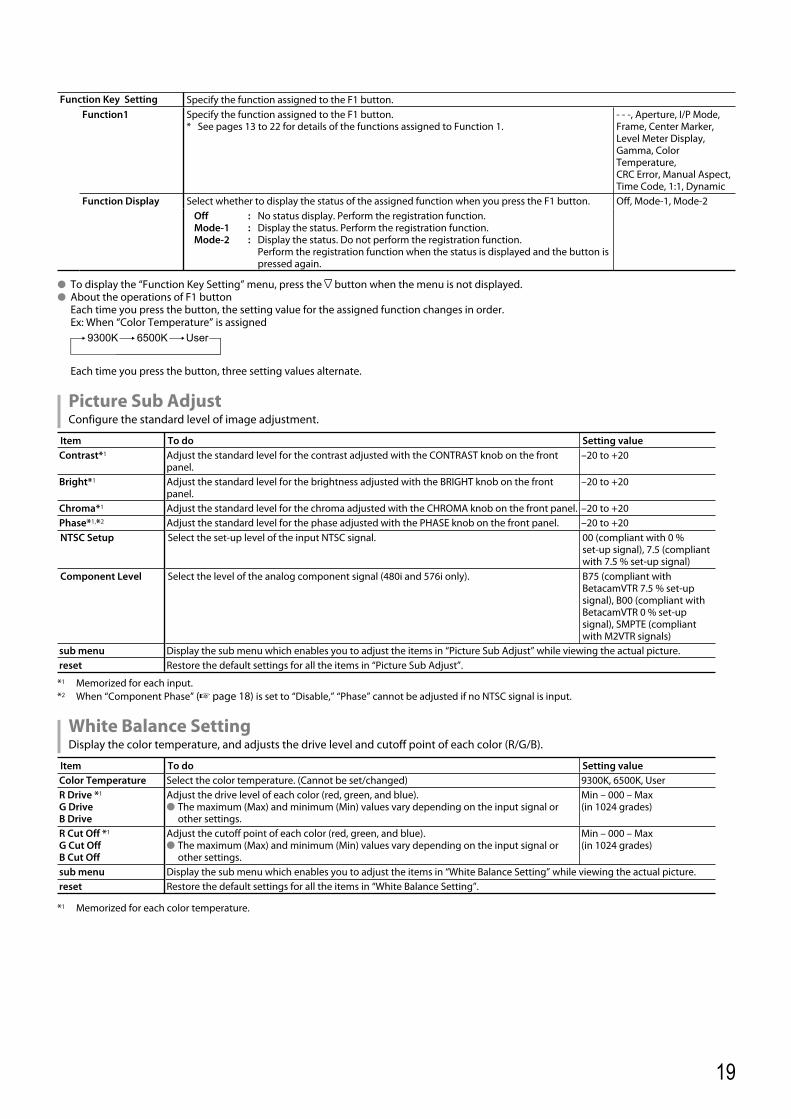
Function Key Setting Specify the function assigned to the F1 button.Function1 Specify the function assigned to the F1 button.
* See pages 13 to 22 for details of the functions assigned to Function 1.- - -, Aperture, I/P Mode, Frame, Center Marker, Level Meter Display, Gamma, Color Temperature, CRC Error, Manual Aspect,Time Code, 1:1, Dynamic
Function Display Select whether to display the status of the assigned function when you press the F1 button. Off, Mode-1, Mode-2OffMode-1Mode-2
:::
No status display. Perform the registration function.Display the status. Perform the registration function.Display the status. Do not perform the registration function.Perform the registration function when the status is displayed and the button is pressed again.
● To display the “Function Key Setting” menu, press the button when the menu is not displayed.● About the operations of F1 button Each time you press the button, the setting value for the assigned function changes in order. Ex: When “Color Temperature” is assigned
Each time you press the button, three setting values alternate.
Picture Sub AdjustConfigure the standard level of image adjustment.
Item To do Setting valueContrast*1 Adjust the standard level for the contrast adjusted with the CONTRAST knob on the front
panel.–20 to +20
Bright*1 Adjust the standard level for the brightness adjusted with the BRIGHT knob on the front panel.
–20 to +20
Chroma*1 Adjust the standard level for the chroma adjusted with the CHROMA knob on the front panel. –20 to +20Phase*1,*2 Adjust the standard level for the phase adjusted with the PHASE knob on the front panel. –20 to +20NTSC Setup Select the set-up level of the input NTSC signal. 00 (compliant with 0 %
set-up signal), 7.5 (compliant with 7.5 % set-up signal)
Component Level Select the level of the analog component signal (480i and 576i only). B75 (compliant with BetacamVTR 7.5 % set-up signal), B00 (compliant with BetacamVTR 0 % set-up signal), SMPTE (compliant with M2VTR signals)
sub menu Display the sub menu which enables you to adjust the items in “Picture Sub Adjust” while viewing the actual picture.reset Restore the default settings for all the items in “Picture Sub Adjust”.
*1 Memorized for each input.*2 When “Component Phase” (☞ page 18) is set to “Disable,” “Phase” cannot be adjusted if no NTSC signal is input.
White Balance SettingDisplay the color temperature, and adjusts the drive level and cutoff point of each color (R/G/B).
Item To do Setting valueColor Temperature Select the color temperature. (Cannot be set/changed) 9300K, 6500K, UserR Drive *1
G DriveB Drive
Adjust the drive level of each color (red, green, and blue). ● The maximum (Max) and minimum (Min) values vary depending on the input signal or
other settings.
Min – 000 – Max (in 1024 grades)
R Cut Off *1
G Cut OffB Cut Off
Adjust the cutoff point of each color (red, green, and blue). ● The maximum (Max) and minimum (Min) values vary depending on the input signal or
other settings.
Min – 000 – Max(in 1024 grades)
sub menu Display the sub menu which enables you to adjust the items in “White Balance Setting” while viewing the actual picture.reset Restore the default settings for all the items in “White Balance Setting”.
*1 Memorized for each color temperature.
DT-V9L5_EN_1.indb 19DT-V9L5_EN_1.indb 19 10/10/2012 5:18:53 PM10/10/2012 5:18:53 PM

20
Remote SettingSettings for the external control.
Item To do Setting valueParallel Type Select a control method of the MAKE/TRIGGER terminal. Make, Trigger, SetPin1
Assign the control functions to the pins of the MAKE/TRIGGER terminal.• Assign a function to each pin terminal by selecting “Set” in “Parallel Type” mentioned
above.
☞ "Display" in "Functions controlled by the MAKE/TRIGGER system" on page 24
Pin2Pin3Pin4Pin5Pin6 The functions are assigned for “Pin6” – “Pin8” and you cannot change the assignment of
these functions.Tally
Pin7 EnablePin8 GND
InformationSettings for the information display of the monitor.
Item To do Setting valueSource ID Select whether the name assigned in “Character Setting” (☞ below) is displayed on the
screen (☞ “On the Information Display” on page 11).• When “Auto” is selected, the display color synchronizes with the color of the tally lamp
while the tally lamp is lit.
Off, On, Auto
Character Setting Assign a name to each video source as you like (10 characters at maximum). You can also enter a name using the RS-232C system. (☞ Page 22)
Status Display Display/Hide the status of the current input and the setting of MUTING. (☞ "On the Status Display" on page 12)
Auto, Off, On
Time Code Display/Hide the Time Code. Off, OnTime Code Select Select the type of the TIME CODE display. VITC*1, LTC*1, D-VITCCRC Error Display/Hide the CRC error when the HD SDI signal is input. (☞ "On the Information Display"
on page 11)Off, On
Sub Hour Meter Display the hours of use (unit: hour). The usage time can be reset to 0.Model Display the model name of the monitor.Version Display the version of the monitor.Hour Meter*2 Display the total hours of use (unit: hour). This item is used for maintenance of the monitor. You cannot reset this item.
*1 Ancillary time code*2 ”Hour Meter” and settings specified using the Picture adjustment knob (☞ 4 on page 10) are not reset.
Control Lock*3 Setting values: Off, Volume Lock, All LockSettings for disabling the buttons on the front panel.
*3 • The following operations are not available when “Volume Lock” is selected. - Picture adjustment knob
• The “All Lock” function disables to control the buttons on the front panel. But following operations are available. - Turning on/off (on standby) the monitor - Displaying the Set-Up Menu by pressing button while holding button and turning “Control Lock” to “Off” - Operating the monitor by an external controlIf you try other operations, “Control lock on!” appears on the screen.
Language Setting values: English, Deutsch, Français, Español, Italiano, PуccкийSelect the displayed language for the menu, etc.
Menu Configuration (cont.)
DT-V9L5_EN_1.indb 20DT-V9L5_EN_1.indb 20 10/10/2012 5:18:53 PM10/10/2012 5:18:53 PM
21
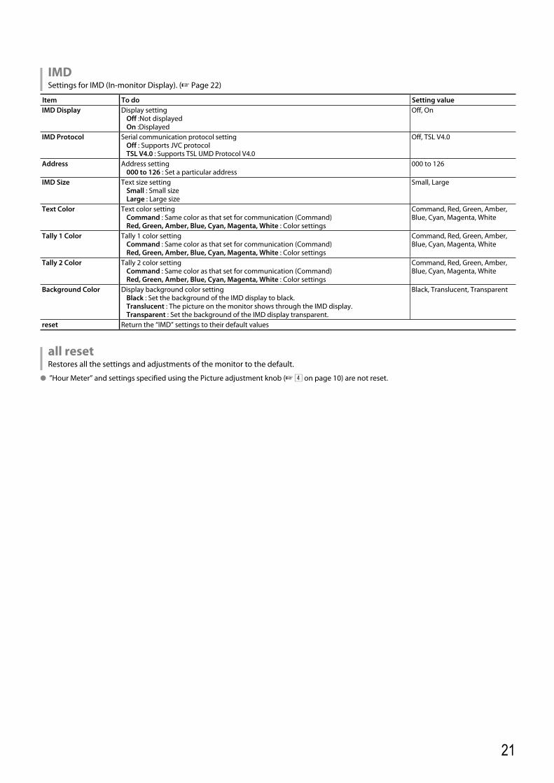
IMDSettings for IMD (In-monitor Display). (☞ Page 22)
Item To do Setting valueIMD Display Display setting
Off :Not displayed On :Displayed
Off, On
IMD Protocol Serial communication protocol settingOff : Supports JVC protocolTSL V4.0 : Supports TSL UMD Protocol V4.0
Off, TSL V4.0
Address Address setting000 to 126 : Set a particular address
000 to 126
IMD Size Text size settingSmall : Small sizeLarge : Large size
Small, Large
Text Color Text color settingCommand : Same color as that set for communication (Command)Red, Green, Amber, Blue, Cyan, Magenta, White : Color settings
Command, Red, Green, Amber, Blue, Cyan, Magenta, White
Tally 1 Color Tally 1 color settingCommand : Same color as that set for communication (Command)Red, Green, Amber, Blue, Cyan, Magenta, White : Color settings
Command, Red, Green, Amber, Blue, Cyan, Magenta, White
Tally 2 Color Tally 2 color settingCommand : Same color as that set for communication (Command)Red, Green, Amber, Blue, Cyan, Magenta, White : Color settings
Command, Red, Green, Amber, Blue, Cyan, Magenta, White
Background Color Display background color settingBlack : Set the background of the IMD display to black.Translucent : The picture on the monitor shows through the IMD display.Transparent : Set the background of the IMD display transparent.
Black, Translucent, Transparent
reset Return the “IMD” settings to their default values
all resetRestores all the settings and adjustments of the monitor to the default.
● ”Hour Meter” and settings specified using the Picture adjustment knob (☞ 4 on page 10) are not reset.
DT-V9L5_EN_1.indb 21DT-V9L5_EN_1.indb 21 10/10/2012 5:18:54 PM10/10/2012 5:18:54 PM
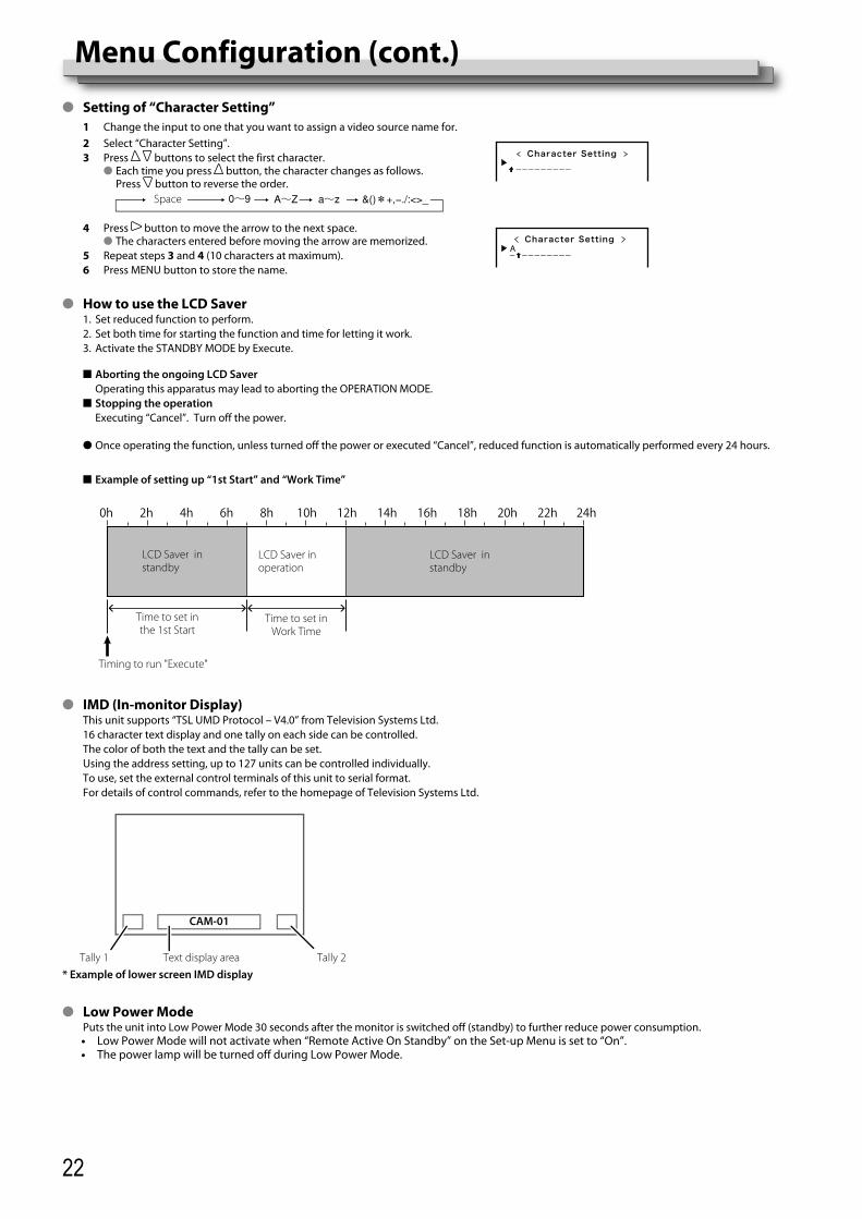
22
● Setting of “Character Setting”1 Change the input to one that you want to assign a video source name for.2 Select “Character Setting”.3 Press buttons to select the first character.
● Each time you press button, the character changes as follows. Press button to reverse the order.
Space
Character Setting
4 Press button to move the arrow to the next space.● The characters entered before moving the arrow are memorized.
5 Repeat steps 3 and 4 (10 characters at maximum).6 Press MENU button to store the name.
Character Setting
● How to use the LCD Saver 1. Set reduced function to perform. 2. Set both time for starting the function and time for letting it work. 3. Activate the STANDBY MODE by Execute.
■ Aborting the ongoing LCD Saver Operating this apparatus may lead to aborting the OPERATION MODE. ■ Stopping the operation Executing “Cancel”. Turn off the power.
● Once operating the function, unless turned off the power or executed “Cancel”, reduced function is automatically performed every 24 hours.
■ Example of setting up “1st Start” and “Work Time”
● IMD (In-monitor Display) This unit supports “TSL UMD Protocol – V4.0” from Television Systems Ltd. 16 character text display and one tally on each side can be controlled. The color of both the text and the tally can be set. Using the address setting, up to 127 units can be controlled individually. To use, set the external control terminals of this unit to serial format. For details of control commands, refer to the homepage of Television Systems Ltd.
● Low Power Mode Puts the unit into Low Power Mode 30 seconds after the monitor is switched off (standby) to further reduce power consumption.
• Low Power Mode will not activate when “Remote Active On Standby” on the Set-up Menu is set to “On”.• The power lamp will be turned off during Low Power Mode.
Time to set in the 1st Start
0h 2h 4h 6h 8h 10h 12h 14h 16h 18h 20h 22h 24h
Timing to run "Execute"
LCD Saver in standby
LCD Saver in operation
Time to set in Work Time
CAM-01
Text display area* Example of lower screen IMD display
Tally 2Tally 1
LCD Saver in standby
Menu Configuration (cont.)
DT-V9L5_EN_1.indb 22DT-V9L5_EN_1.indb 22 10/10/2012 5:18:54 PM10/10/2012 5:18:54 PM
23
About the external controlThis monitor has three external control terminals.● MAKE/TRIGGER terminal (RJ-45): The following external control
systems are available.(1) MAKE (make contact) system: Controls the monitor by short-circuiting the corresponding pin
terminal to the GND pin terminal, or disconnecting (opening) it.(2) TRIGGER (trigger) system: Controls the monitor by sending the pulse signal instantaneously
to the corresponding pin terminal.
☞ “Using the MAKE/TRIGGER system”on the right● RS-232C terminal (D-sub 9-pin): Controls the monitor with the
RS-232C system. (☞ “Using the serial communication” on page 24)Set the following items of “Remote Setting” in Set-Up Menu according to the external control terminal and control system. (☞ “Parallel Type” on page 20)
Control terminal Control system
The settings of this unit“Parallel Type” setting
MAKE/TRIGGER terminal
Parallel Type MAKE MakeTRIGGER Trigger
RS-232C terminal
Serial communication
RS-232C —
*1 For a monitor connected to a personal computer etc, select the terminal the equipment is actually connected to.
“MAKE” takes precedence over other controls.● You can use external control even when “Control Lock” is set to
“Volume Lock” or “All Lock”. (☞ page 20)● When the monitor is off (on standby), external control is not
available. But certain external controls (starting/terminating communication, turning on the monitor) are available through the serial communication. (☞ page 25)
<MAKE/TRIGGER system>You can control the monitor by a personal computer or dedicated controller*2.● “Using the MAKE/TRIGGER system” on the right.*2 The controller is not commercially available. Consult your dealer if
you need it.
<Serial communication>
● For the details, see page 24.
PC, etc.
External Control
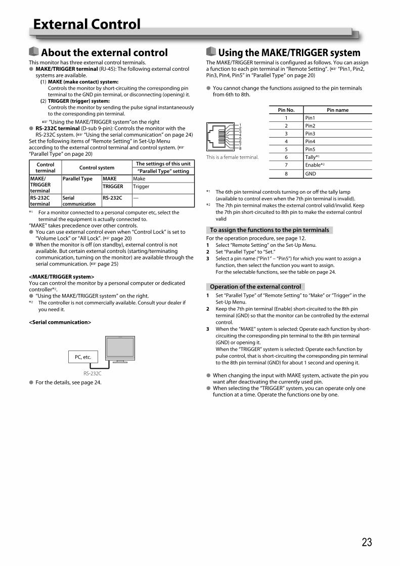
Using the MAKE/TRIGGER systemThe MAKE/TRIGGER terminal is configured as follows. You can assign a function to each pin terminal in “Remote Setting”. (☞ “Pin1, Pin2, Pin3, Pin4, Pin5” in “Parallel Type” on page 20)
● You cannot change the functions assigned to the pin terminals from 6th to 8th.
Pin No. Pin name1 Pin12 Pin23 Pin34 Pin45 Pin5
This is a female terminal. 6 Tally*1
7 Enable*2
8 GND
*1 The 6th pin terminal controls turning on or off the tally lamp (available to control even when the 7th pin terminal is invalid).
*2 The 7th pin terminal makes the external control valid/invalid. Keep the 7th pin short-circuited to 8th pin to make the external control valid
To assign the functions to the pin terminalsFor the operation procedure, see page 12.1 Select “Remote Setting” on the Set-Up Menu.2 Set “Parallel Type” to “Set.”3 Select a pin name (“Pin1” – “Pin5”) for which you want to assign a
function, then select the function you want to assign. For the selectable functions, see the table on page 24.
Operation of the external control1 Set “Parallel Type” of “Remote Setting” to “Make” or “Trigger” in the
Set-Up Menu.2 Keep the 7th pin terminal (Enable) short-circuited to the 8th pin
terminal (GND) so that the monitor can be controlled by the external control.
3 When the “MAKE” system is selected: Operate each function by short-circuiting the corresponding pin terminal to the 8th pin terminal (GND) or opening it.
When the “TRIGGER” system is selected: Operate each function by pulse control, that is short-circuiting the corresponding pin terminal to the 8th pin terminal (GND) for about 1 second and opening it.
● When changing the input with MAKE system, activate the pin you want after deactivating the currently used pin.
● When selecting the “TRIGGER” system, you can operate only one function at a time. Operate the functions one by one.
RS-232C
DT-V9L5_EN_1.indb 23DT-V9L5_EN_1.indb 23 10/10/2012 5:18:55 PM10/10/2012 5:18:55 PM
24
<Functions controlled by the MAKE/TRIGGER system>Display Functions to be controlled Opening Short-circuiting
– – – No function — —Tally Color Tally lamp color selection*1 Green RedTally Type Tally lamp lighting method selection Whole One half at a timeTally-L(R) Light the left half of the tally lamp in red*2 On OffTally-R(G) Light the right half of the tally lamp in green*2 On OffSDI-1 Changes the input to “SDI 1” Invalid ValidSDI-2 Changes the input to “SDI 2” Invalid ValidHDMI Changes the input to “HDMI” Invalid ValidVideo/Component Changes the input to “VIDEO/COMPO.” Invalid ValidMarker The marker indication Off OnCenter Marker The center marker indication Off OnFrame Indication of the area of the specified aspect ratio Off OnMarker Select Selects the items of “Marker”*3 Non-“R-” items “R-” itemsManual Aspect Changes the aspect ratio 4:3 16:91:1 Displays in 1:1 mode Off OnStatus Status display*4 ☞ “On the Status Display” on page 12Level Meter Audio level meter display *5
Time Code Time code display Off OnSource ID ☞ “Source ID” in “Information” on page 20 *6
Color Off Color off Color MonochromeScreens Check Screens check *7
I/P Mode Change a mode according to a input picture *8
Muting Muting on/off Off OnDimmer Change the intensity of the button lamps Normal DarkWave Form Wave form display Off OnVector Scope Vector scope display Off OnHistogram Histogram display Off OnDynamic Adjusts the picture to be suitable for a bright place Invalid Valid
*1 Can be controlled when “Tally Type” (“Set-Up Menu” → “Function Setting” → “Tally Setting”) is set to “Normal”.*2 Can be controlled when “Tally Type” (“Set-Up Menu” → “Function Setting” → “Tally Setting”) is set to “Half”.*3 Selects which functions in “Marker” are activated, non-“R-” items or “R-” items. (☞ “Marker” on page 15)*4 Displays the information shown when INPUT SELECT button of the current input is pressed. (☞ “On the Status Display” on page 12) While controlling
with the MAKE system, the information is displayed only at the moment of short-circuiting.*5 While controlling with the MAKE system, the level meter is switched between displayed (short-circuiting) and hidden (opening). When “Level Meter
Display” is set to “Off,” the level meter is not displayed (“No Effect” appears). While controlling with the TRIGGER system, the pattern of the audio channel display is switched.*6 While controlling with the MAKE system, the available set-up options will be the setting value currently selected in “Source ID” (“On” or “Auto” [short-
circuiting]) and “Off” (opening). While controlling with the TRIGGER system, uses the same set-up option as those in the Set-Up Menu. (☞ “Source ID” in “Information” on page 20)
*7 While controlling with the MAKE system, the screen is switched between normal screen (opening) and blue screen (short-circuiting). While controlling with the TRIGGER system, the screen changes in the same way as when pressing SCR. CHK. button (☞ 7 on page 10).
*8 Must be controlled with the TRIGGER system. The mode is switched between “Normal” and “Cinema” (This function cannot be controlled with the MAKE system).
● You cannot assign the same function to different pin terminals.● The TRIGGER system switches each function by short-circuiting the pin terminal for about 1 second and opening it.
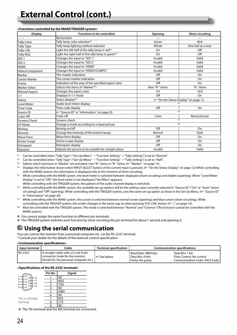
Using the serial communicationYou can control the monitor from a personal computer etc. via the RS-232C terminal.* Consult your dealer for the details of the external control specification.
<Communication specifications>Input terminal Cable Terminal specification Communication specifications
RS-232C A straight cable with a D-sub 9-pin connector (male for the monitor, female for the personal computer etc.)
☞ See belowBaud Rate: 4800 bps Stop Bits: 1 bitData Bits: 8 bits Flow Control: No controlParity: No parity Communication Code: ASCII Code
Pin No. Signal1 NC2 RXD3 TXD4 NC5 GND
This is a female terminal.
6 NC7 RTS8 CTS9 NC
● The 7th terminal and the 8th terminal are connected.
External Control (cont.)
<Specifications of the RS-232C terminal>
DT-V9L5_EN_1.indb 24DT-V9L5_EN_1.indb 24 10/10/2012 5:18:56 PM10/10/2012 5:18:56 PM
25
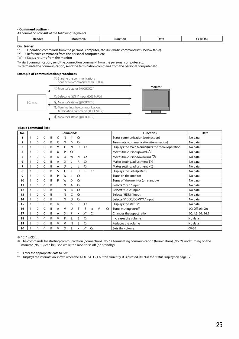
<Command outline>All commands consist of the following segments.
Header Monitor ID Function Data Cr (0Dh)
On Header“!” : Operation commands from the personal computer, etc. (☞ <Basic command list> below table).“?” : Reference commands from the personal computer, etc.“@” : Status returns from the monitorTo start communication, send the connection command from the personal computer etc.To terminate the communication, send the termination command from the personal computer etc.
Example of communication procedures
<Basic command list>No. Commands Functions Data
1 ! 0 0 B C N 1 Cr Starts communication (connection) No data2 ! 0 0 B C N 0 Cr Terminates communication (termination) No data3 ! 0 0 B M E N U Cr Displays the Main Menu/Quits the menu operation No data
4 ! 0 0 B U P Cr Moves the cursor upward ( ) No data
5 ! 0 0 B D O W N Cr Moves the cursor downward ( ) No data
6 ! 0 0 B A D J R Cr Makes setting/adjustment ( ) No data7 ! 0 0 B A D J L Cr Makes setting/adjustment ( ) No data8 ! 0 0 B S E T U P Cr Displays the Set-Up Menu No data9 ! 0 0 B P W 1 Cr Turns on the monitor No data
10 ! 0 0 B P W 0 Cr Turns off the monitor (on standby) No data11 ! 0 0 B I N A Cr Selects “SDI 1” input No data12 ! 0 0 B I N B Cr Selects “SDI 2” input No data13 ! 0 0 B I N C Cr Selects “HDMI” input No data14 ! 0 0 B I N D Cr Selects “VIDEO/COMPO.” input No data15 ! 0 0 B D I S P Cr Displays the status*2 No data16 ! 0 0 B A M U T E x x*1 Cr Turns muting on/off 00: Off, 01: On17 ! 0 0 B A S P x x*1 Cr Changes the aspect ratio 00: 4:3, 01: 16:9
18 ! 0 0 B V P L S Cr Increases the volume No data
19 ! 0 0 B V M N S Cr Reduces the volume No data
20 ! 0 0 B V O L x x*1 Cr Sets the volume 00-30
● “Cr” is 0Dh.● The commands for starting communication (connection) (No. 1), terminating communication (termination) (No. 2), and turning on the
monitor (No. 13) can be used while the monitor is off (on standby).
*1 Enter the appropriate data to “xx.”*2 Displays the information shown when the INPUT SELECT button currently lit is pressed. (☞ “On the Status Display” on page 12)
1 Starting the communication:connection command (!00BCN1Cr)
3 Selecting “SDI 1” input (!00BINACr)
5 Terminating the communication: termination command (!00BCN0Cr)
6 Monitor’s status (@00BOKCr)
4 Monitor’s status (@00BOKCr)
2 Monitor’s status (@00BOKCr)
PC, etc.
Monitor
DT-V9L5_EN_1.indb 25DT-V9L5_EN_1.indb 25 10/10/2012 5:18:56 PM10/10/2012 5:18:56 PM
26
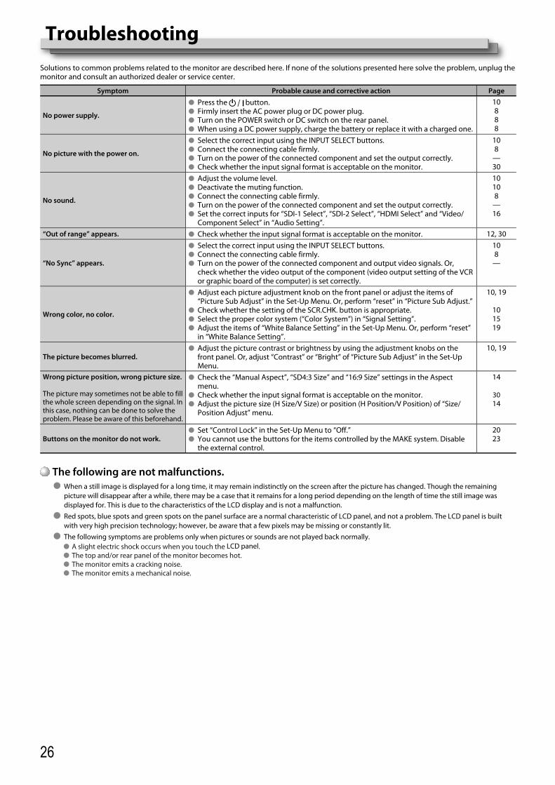
TroubleshootingSolutions to common problems related to the monitor are described here. If none of the solutions presented here solve the problem, unplug the monitor and consult an authorized dealer or service center.
Symptom Probable cause and corrective action Page
No power supply.
● Press the button.● Firmly insert the AC power plug or DC power plug.● Turn on the POWER switch or DC switch on the rear panel.● When using a DC power supply, charge the battery or replace it with a charged one.
10888
No picture with the power on.
● Select the correct input using the INPUT SELECT buttons. ● Connect the connecting cable firmly.● Turn on the power of the connected component and set the output correctly.● Check whether the input signal format is acceptable on the monitor.
108
—30
No sound.
● Adjust the volume level.● Deactivate the muting function.● Connect the connecting cable firmly. ● Turn on the power of the connected component and set the output correctly.● Set the correct inputs for “SDI-1 Select”, “SDI-2 Select”, “HDMI Select” and “Video/
Component Select” in “Audio Setting”.
10108
—16
“Out of range” appears. ● Check whether the input signal format is acceptable on the monitor. 12, 30
“No Sync” appears.
● Select the correct input using the INPUT SELECT buttons.● Connect the connecting cable firmly. ● Turn on the power of the connected component and output video signals. Or,
check whether the video output of the component (video output setting of the VCR or graphic board of the computer) is set correctly.
108
—
Wrong color, no color.
● Adjust each picture adjustment knob on the front panel or adjust the items of “Picture Sub Adjust” in the Set-Up Menu. Or, perform “reset” in “Picture Sub Adjust.”
● Check whether the setting of the SCR.CHK. button is appropriate.● Select the proper color system (“Color System”) in “Signal Setting”.● Adjust the items of “White Balance Setting” in the Set-Up Menu. Or, perform “reset”
in “White Balance Setting”.
10, 19
101519
The picture becomes blurred.● Adjust the picture contrast or brightness by using the adjustment knobs on the
front panel. Or, adjust “Contrast” or “Bright” of “Picture Sub Adjust” in the Set-Up Menu.
10, 19
Wrong picture position, wrong picture size.
The picture may sometimes not be able to fill the whole screen depending on the signal. In this case, nothing can be done to solve the problem. Please be aware of this beforehand.
● Check the “Manual Aspect”, “SD4:3 Size” and “16:9 Size” settings in the Aspect menu.
● Check whether the input signal format is acceptable on the monitor.● Adjust the picture size (H Size/V Size) or position (H Position/V Position) of “Size/
Position Adjust” menu.
14
3014
Buttons on the monitor do not work.● Set “Control Lock” in the Set-Up Menu to “Off.”● You cannot use the buttons for the items controlled by the MAKE system. Disable
the external control.
2023
The following are not malfunctions.● When a still image is displayed for a long time, it may remain indistinctly on the screen after the picture has changed. Though the remaining
picture will disappear after a while, there may be a case that it remains for a long period depending on the length of time the still image was displayed for. This is due to the characteristics of the LCD display and is not a malfunction.
● Red spots, blue spots and green spots on the panel surface are a normal characteristic of LCD panel, and not a problem. The LCD panel is built with very high precision technology; however, be aware that a few pixels may be missing or constantly lit.
● The following symptoms are problems only when pictures or sounds are not played back normally.● A slight electric shock occurs when you touch the LCD panel.● The top and/or rear panel of the monitor becomes hot.● The monitor emits a cracking noise.● The monitor emits a mechanical noise.
DT-V9L5_EN_1.indb 26DT-V9L5_EN_1.indb 26 10/10/2012 5:18:57 PM10/10/2012 5:18:57 PM

27
Self-check programThis monitor has a self-check function, which allows it to detect malfunctions and alert you. This makes troubleshooting easier. Whenever a problem occurs, one or some of the INPUT SELECT lamps will flash. If this happens, follow the steps below and contact your dealer to resolve the problem.
HDMISCOPE
INPUT
When the screen goes blank, and one or some of the INPUT SELECT lamps (SDI 1/SDI 2) on the front control panel start flashing...
1 Check which lamps are flashing.
2 Press button to turn off (on standby) the monitor.
3 Turn off the power switch and DC switch on the rear panel.
4 When the AC power supply is used: Disconnect the AC power cord from the AC outlet.When a DC power supply is used: Detach the battery or disconnect the plug from the DC IN terminal.
5 Contact your dealer with the information about which lamps were flashing.
● If you turn on the monitor soon after turning it off (or after a short-term power failure), the INPUT SELECT lamps may flash and no image may be displayed.
When this happens, turn off power and wait at least 10 seconds before turning on the monitor again. If the INPUT SELECT lamps do not flash, you can use the monitor as normal.● The self-check function does not work when the setup menu “Remote Active On Standby” is set to “Off” and you turn off the monitor (put the
monitor in standby).
DT-V9L5_EN_1.indb 27DT-V9L5_EN_1.indb 27 10/10/2012 5:18:58 PM10/10/2012 5:18:58 PM
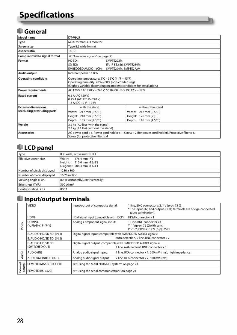
28
Specifications
GeneralModel name DT-V9L5Type Multi format LCD monitorScreen size Type 8.2 wide format Aspect ratio 16:10
Compliant video signal format ☞ “Available signals” on page 30Format HD SDI: SMPTE292M
SD SDI: ITU-R BT.656, SMPTE259MEMBEDDED AUDIO 16CH: SMPTE299M, SMPTE272M
Audio output Internal speaker: 1.0 W
Operating conditions Operating temperature: 5°C – 35°C (41°F – 95°F)Operating humidity: 20% – 80% (non-condensing)(Slightly variable depending on ambient conditions for installation.)
Power requirements AC 120 V / AC 220 V – 240 V, 50 Hz/60 Hz or DC 12 V – 17 V
Rated current 0.5 A (AC 120 V)0.25 A (AC 220 V– 240 V)1.3 A (DC 12 V - 17 V)
External dimensions(excluding protruding parts)
with the stand without the standWidth: 217 mm (8 5/8˝) Width: 217 mm (8 5/8˝)Height: 218 mm (8 5/8˝) Height: 176 mm (7˝)Depth: 185 mm (7 3/8˝) Depth: 116 mm (4 5/8˝)
Weight 3.2 kg (7.0 lbs) (with the stand)2.3 kg (5.1 lbs) (without the stand)
Accessories AC power cord x 1, Power cord holder x 1, Screw x 2 (for power cord holder), Protective filter x 1, Screw (for protective filter) x 4
LCD panelType 8.2˝ wide, active matrix TFTEffective screen size Width: 176.4 mm (7˝)
Height: 110.4 mm (4 3/8˝)Diagonal: 208.3 mm (8 1/4˝)
Number of pixels displayed 1280 x 800Number of colors displayed 16.70 millionViewing angle (TYP.) 80° (Horizontally), 80° (Vertically)Brightness (TYP.) 360 cd/m2
Contrast ratio (TYP.) 800:1
Input/output terminals
Vide
o
VIDEO Input/output of composite signal: 1 line, BNC connector x 2, 1 V (p-p), 75 Ω* The input (IN) and output (OUT) terminals are bridge-connected
(auto termination).HDMI HDMI signal input (compatible with HDCP): HDMI connector x 1COMPO. (Y, Pb/B-Y, Pr/R-Y)
Analog Component signal input: 1 Line, BNC connector x3Y: 1 V(p-p), 75 Ω(with sync)PB/B-Y, PR/R-Y: 0.7 V (p-p), 75 Ω
E. AUDIO HD/SD SDI (IN 1) Digital signal input (compatible with EMBEDDED AUDIO signals): auto detection, 2 line, BNC connector x 2E. AUDIO HD/SD SDI (IN 2)
E. AUDIO HD/SD SDI(SWITCHED OUT)
Digital signal output (compatible with EMBEDDED AUDIO signals): 1 line switched out, BNC connector x 1
Aud
io AUDIO (IN) Analog audio signal input: 1 line, RCA connector x 1, 500 mV (rms), high impedance
AUDIO (MONITOR OUT) Analog audio signal output: 2 line, RCA connector x 2, 500 mV (rms)
Exte
rnal
co
ntro
l REMOTE (MAKE/TRIGGER) ☞ “Using the MAKE/TRIGGER system” on page 23
REMOTE (RS-232C) ☞ “Using the serial communication” on page 24
DT-V9L5_EN_1.indb 28DT-V9L5_EN_1.indb 28 10/10/2012 5:18:58 PM10/10/2012 5:18:58 PM

29
Dimensions Unit: mm (inch)
DT-V9L5<Front view> <Side view>
100
7537
.5(1
1/2
)
55 (2
1/4
)10
0
202 (8)
217 (8 5/8)
176
(7)
218
(8 5
/8)*
/ 181
(7 1
/4)*
*
186 (7 3/8)
75
13 (5/8)
26.5 (1 1/8)
1.3 (1/16)
185 (7 3/8)
116 (4 5/8)
Notice on transportationThis monitor is precision equipment and needs dedicated packing material for transportation.Never use any packing material supplied from sources other than JVC or JVC-authorized dealers.
● For easy understanding, pictures and illustrations are shown by being emphasized, omitted or composed, and may be slightly different from actual products.
● Design and specifications are subject to change without notice.● All company names and product names mentioned herein are used for identification purposes only, and may be the trademarks or
registered trademarks of their respective companies.
<Rear view>
*at the higher position**at the lower position
VESA mounting holes(8-M4, depth:10mm)
DT-V9L5_EN_1.indb 29DT-V9L5_EN_1.indb 29 10/10/2012 5:18:59 PM10/10/2012 5:18:59 PM
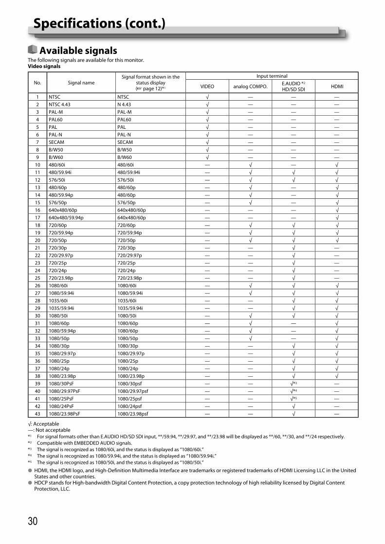
30
Specifications (cont.)
Available signalsThe following signals are available for this monitor.Video signals
No. Signal nameSignal format shown in the
status display(☞ page 12)*1
Input terminal
VIDEO analog COMPO. E.AUDIO *2
HD/SD SDI HDMI
1 NTSC NTSC √ — — —2 NTSC 4.43 N 4.43 √ — — —3 PAL-M PAL-M √ — — —4 PAL60 PAL60 √ — — —5 PAL PAL √ — — —6 PAL-N PAL-N √ — — —7 SECAM SECAM √ — — —8 B/W50 B/W50 √ — — —9 B/W60 B/W60 √ — — —
10 480/60i 480/60i — √ — √11 480/59.94i 480/59.94i — √ √ √12 576/50i 576/50i — √ √ √13 480/60p 480/60p — √ — √14 480/59.94p 480/60p — √ — √15 576/50p 576/50p — √ — √16 640x480/60p 640x480/60p — — — √17 640x480/59.94p 640x480/60p — — — √18 720/60p 720/60p — √ √ √19 720/59.94p 720/59.94p — √ √ √20 720/50p 720/50p — √ √ √21 720/30p 720/30p — — √ —22 720/29.97p 720/29.97p — — √ —23 720/25p 720/25p — — √ —24 720/24p 720/24p — — √ —25 720/23.98p 720/23.98p — — √ —26 1080/60i 1080/60i — √ √ √27 1080/59.94i 1080/59.94i — √ √ √28 1035/60i 1035/60i — — √ √29 1035/59.94i 1035/59.94i — — √ √30 1080/50i 1080/50i — √ √ √31 1080/60p 1080/60p — √ — √32 1080/59.94p 1080/60p — √ — √33 1080/50p 1080/50p — √ — √34 1080/30p 1080/30p — — √ √35 1080/29.97p 1080/29.97p — — √ √36 1080/25p 1080/25p — — √ √37 1080/24p 1080/24p — — √ √38 1080/23.98p 1080/23.98p — — √ √39 1080/30PsF 1080/30psf — — √*3 —40 1080/29.97PsF 1080/29.97psf — — √*4 —41 1080/25PsF 1080/25psf — — √*5 —42 1080/24PsF 1080/24psf — — √ —43 1080/23.98PsF 1080/23.98psf — — √ —
√: Acceptable—: Not acceptable*1 For signal formats other than E.AUDIO HD/SD SDI input, **/59.94, **/29.97, and **/23.98 will be displayed as **/60, **/30, and **/24 respectively.*2 Compatible with EMBEDDED AUDIO signals.*3 The signal is recognized as 1080/60i, and the status is displayed as “1080/60i.”*4 The signal is recognized as 1080/59.94i, and the status is displayed as “1080/59.94i.”*5 The signal is recognized as 1080/50i, and the status is displayed as “1080/50i.”
● HDMI, the HDMI logo, and High-Definition Multimedia Interface are trademarks or registered trademarks of HDMI Licensing LLC in the United States and other countries.
● HDCP stands for High-bandwidth Digital Content Protection, a copy protection technology of high reliability licensed by Digital Content Protection, LLC.
DT-V9L5_EN_1.indb 30DT-V9L5_EN_1.indb 30 10/10/2012 5:19:00 PM10/10/2012 5:19:00 PM

31
MEMO
DT-V9L5_EN_1.indb 31DT-V9L5_EN_1.indb 31 10/10/2012 5:19:01 PM10/10/2012 5:19:01 PM

© 2012 JVC KENWOOD Corporation LCT2704-001A
MU
LTI FOR
MAT LC
D M
ON
ITOR
D
T-V9L5
DT-V9L5_EN_1.indb 32DT-V9L5_EN_1.indb 32 10/10/2012 5:19:01 PM10/10/2012 5:19:01 PM