multi-functional power meter
TRANSCRIPT
www.deltaww.com
Multi-Functional Power Meter DPM-C520 / DPM-C520W / DPM-C320Operation Manual
Industrial Automation HeadquartersDelta Electronics, Inc. Taoyuan Technology CenterNo.18, Xinglong Rd., Taoyuan District, Taoyuan City 33068, TaiwanTEL: 886-3-362-6301 / FAX: 886-3-371-6301
AsiaDelta Electronics (Shanghai) Co., Ltd.No.182 Minyu Rd., Pudong Shanghai, P.R.C.Post code : 201209 TEL: 86-21-6872-3988 / FAX: 86-21-6872-3996Customer Service: 400-820-9595
Delta Electronics (Japan), Inc.Tokyo Office Industrial Automation Sales Department 2-1-14 Shibadaimon, Minato-kuTokyo, Japan 105-0012TEL: 81-3-5733-1155 / FAX: 81-3-5733-1255
Delta Electronics (Korea), Inc.Seoul Office1511, 219, Gasan Digital 1-Ro., Geumcheon-gu, Seoul, 08501 South KoreaTEL: 82-2-515-5305 / FAX: 82-2-515-5302
Delta Energy Systems (Singapore) Pte Ltd.4 Kaki Bukit Avenue 1, #05-04, Singapore 417939TEL: 65-6747-5155 / FAX: 65-6744-9228
Delta Electronics (India) Pvt. Ltd.Plot No.43, Sector 35, HSIIDC Gurgaon, PIN 122001, Haryana, IndiaTEL: 91-124-4874900 / FAX : 91-124-4874945
Delta Electronics (Thailand) PCL. 909 Soi 9, Moo 4, Bangpoo Industrial Estate (E.P.Z), Pattana 1 Rd., T.Phraksa, A.Muang, Samutprakarn 10280, ThailandTEL: 66-2709-2800 / FAX : 662-709-2827
Delta Electronics (Australia) Pty Ltd.Unit 20-21/45 Normanby Rd., Notting Hill Vic 3168, AustraliaTEL: 61-3-9543-3720
AmericasDelta Electronics (Americas) Ltd.Raleigh OfficeP.O. Box 12173, 5101 Davis Drive, Research Triangle Park, NC 27709, U.S.A.TEL: 1-919-767-3813 / FAX: 1-919-767-3969
Delta Greentech (Brasil) S/ASão Paulo OfficeRua Itapeva, 26 – 3˚ Andar - Bela VistaCEP: 01332-000 – São Paulo – SP - BrasilTEL: 55-11-3530-8643 / 55-11-3530-8640
Delta Electronics International Mexico S.A. de C.V.Mexico OfficeGustavo Baz No. 309 Edificio E PB 103Colonia La Loma, CP 54060Tlalnepantla, Estado de MéxicoTEL: 52-55-3603-9200
*We reserve the right to change the information in this catalogue without prior notice.
EMEAHeadquarters: Delta Electronics (Netherlands) B.V. Sales: [email protected] Marketing: [email protected] Technical Support: [email protected] Customer Support: [email protected] Service: [email protected]: +31(0)40 800 3900
BENELUX: Delta Electronics (Netherlands) B.V.De Witbogt 20, 5652 AG Eindhoven, The Netherlands Mail: [email protected]: +31(0)40 800 3900
DACH: Delta Electronics (Netherlands) B.V.Coesterweg 45, D-59494 Soest, GermanyMail: [email protected]: +49(0)2921 987 0
France: Delta Electronics (France) S.A.ZI du bois Challand 2, 15 rue des Pyrénées, Lisses, 91090 Evry Cedex, France Mail: [email protected]: +33(0)1 69 77 82 60
Iberia: Delta Electronics Solutions (Spain) S.L.UCtra. De Villaverde a Vallecas, 265 1º Dcha Ed. Hormigueras – P.I. de Vallecas 28031 Madrid TEL: +34(0)91 223 74 20
Carrer Llacuna 166, 08018 Barcelona, SpainMail: [email protected]
Italy: Delta Electronics (Italy) S.r.l.Via Meda 2–22060 Novedrate(CO) Piazza Grazioli 18 00186 Roma ItalyMail: [email protected]: +39 039 8900365
Russia: Delta Energy System LLC Vereyskaya Plaza II, office 112 Vereyskaya str. 17 121357 Moscow Russia Mail: [email protected]: +7 495 644 3240
Turkey: Delta Greentech Elektronik San. Ltd. Sti. (Turkey) Şerifali Mah. Hendem Cad. Kule Sok. No:16-A 34775 Ümraniye – İstanbulMail: [email protected]: + 90 216 499 9910
GCC: Delta Energy Systems AG (Dubai BR)P.O. Box 185668, Gate 7, 3rd Floor, Hamarain Centre Dubai, United Arab Emirates Mail: [email protected]: +971(0)4 2690148
Egypt + North Africa: Delta ElectronicsUnit 318, 3rd Floor, Trivium Business Complex, North 90 street, New Cairo, Cairo, Egypt Mail: [email protected]
DPM-093AH20-02 2020/05/06
DPM-C520/C520W/C320 Operation Manual
Revision History Version Revis ion Date
1 s t The f i r s t ve rs ion was pub l ished. 2019/05/15
2 n d Renew t i t l e as DPM-C520/C520W/C320 Opera t ion Manua l . Add new contents concern ing DPM-C320. 2020/05/06

i
DPM-C520/C520W/C320 Operation Manual
Table of Contents
Chapter 1 Product Introduction
1.1 Preface .............................................................................................. 1-2
1.2 Overview ........................................................................................... 1-3
1.3 Safety Precautions ............................................................................. 1-4
Chapter 2 Product Specifications
2.1 Electrical Characteristics ................................................................... 2-2
2.2 Communications Specifications ......................................................... 2-4
2.3 Operating the Display ........................................................................ 2-5 2.3.1 Menu Tree .................................................................................... 2-6
2.4 Dimensions ........................................................................................ 2-8
Chapter 3 Installation
3.1 Installation ........................................................................................ 3-2 3.1.1 Installation Environment ................................................................ 3-2 3.1.2 Installation Notes .......................................................................... 3-2
3.2 Basic Checks ...................................................................................... 3-5
3.3 Wiring ................................................................................................ 3-5 3.3.1 Wiring Diagrams ........................................................................... 3-5 3.3.2 Communication Characteristics........................................................ 3-8
Chapter 4 Operation
4.1 General Operation ............................................................................. 4-3 4.1.1 Setting Menu ................................................................................ 4-3
4.2 DPM-C520 / DPM-C520W Setups ....................................................... 4-4 4.2.1 Unlock the Setting ......................................................................... 4-4 4.2.2 Time Setup (TIM) .......................................................................... 4-4 4.2.3 Date Setup (DAT) .......................................................................... 4-5 4.2.4 Communication Setup (COM) .......................................................... 4-5 4.2.5 System Setup (SYS) ...................................................................... 4-6 4.2.6 Current Transformer Setup (CT) ...................................................... 4-6
i i
4.2.7 Potential Transformer Setup (PT) .................................................... 4-7 4.2.8 Reset Setup (RST) ........................................................................ 4-8 4.2.9 Meter Information (INF) ................................................................ 4-8 4.2.10 Wi-Fi Setup (485 ON/OFF) only available for DPM-C520W ................... 4-8 4.2.11 Alarm Setup ................................................................................. 4-9 4.2.12 Parameter Grouping Setup ............................................................. 4-9
4.3 DPM-C320 Setups ............................................................................ 4-11 4.3.1 Communication Setup (COM) ........................................................ 4-11 4.3.2 System Setup (SYS) .................................................................... 4-11 4.3.3 Current Transformer Setup (CT) .................................................... 4-11 4.3.4 Potential Transformer Setup (PT) .................................................. 4-12 4.3.5 Reset Setup (RST) ...................................................................... 4-12 4.3.6 Meter Information (INF) .............................................................. 4-13 4.3.7 Parameter Grouping Setup ........................................................... 4-13 4.3.8 Language .................................................................................. 4-14
4.4 Wi-Fi Setup (only available for DPM-C520W) .................................. 4-15 4.4.1 Wi-Fi Specification ...................................................................... 4-15 4.4.2 Wireless Access Point (AP) Setup .................................................. 4-15 4.4.3 Advanced Wi-Fi Setup ................................................................. 4-20
4.5 Power Analysis Values ..................................................................... 4-27 4.5.1 Total Harmonic Distortion Measurement ......................................... 4-27
Chapter 5 Parameters and Funcitons
5.1 Overview of Parameters .................................................................... 5-2
Chapter 6 Error Codes
6.1 Error Codes........................................................................................ 6-2
6.2 Alarm Types ...................................................................................... 6-2
Appendix A Accessories
A.1 DCT1000 Series ................................................................................. A-2
A.2 DCT2000 Series ................................................................................. A-4

1-1
1 Chapter 1 Product Introduction
Table of Contents
1.1 Preface ................................................................................................ 1-2
1.2 Overview ............................................................................................. 1-3
1.3 Safety Precautions .............................................................................. 1-4
DPM-C520/C520W/C320 Operat ion Manual
1-2
_1 1.1 Preface
Thank you for choosing this product. This manual provides installation instructions for the DPM-C520/C520W/C320 power meter (DPM-C520W is WiFi edition power meter). The multifunction power meter DPM-C520/C520W/C320 is an obvious choice for any application in terms of power monitoring and control for sectors such as power system, industrial mining supply company, and public facility. Before using the meter, read this manual carefully to ensure proper use of this meter. After reading the manual, keep it in a convenient location for quick reference.
Before you finish reading this manual, observe the following notes.
The installation environment must be free of water vapor, corrosive and flammable gas.
Follow the instructions on the diagram in this manual for wiring the device.
Grounding must be performed correctly and properly according to provisions for related electric work regulations currently effective in the country.
Do not disassemble the meter or alter its wiring when the power is on.
When the power is on, do not touch the terminal area to avoid electric shock.
If you still experience issues when using the device, please contact your distributor or our customer service center. As the product is updated and improved, changes to the specifications will be included in the newest version of the manual which you can get by contacting your distributor or downloading it from the Delta Electronics website (http://www.delta.com.tw/ia/).
Chapter 1 Product Introduct ion
1-3
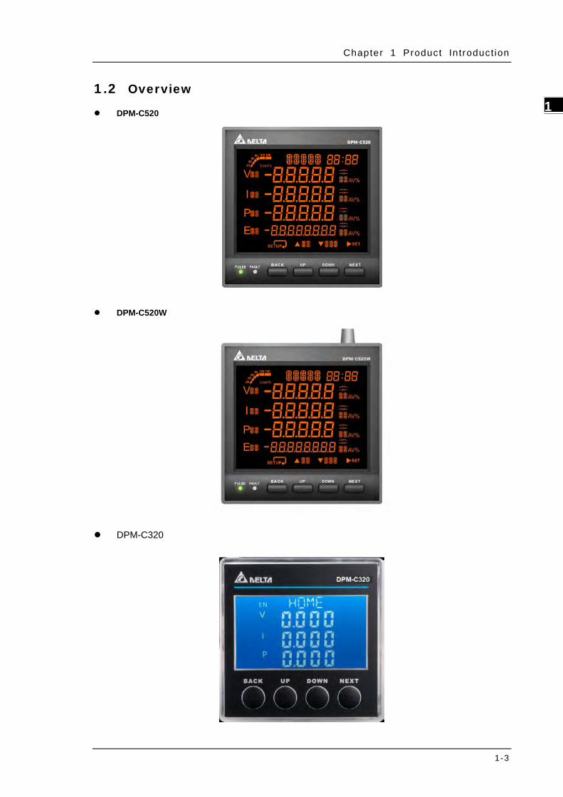
1_ 1.2 Overview
DPM-C520
DPM-C520W
DPM-C320

DPM-C520/C520W/C320 Operat ion Manual
1-4
_1 1.3 Safety Precautions
Installation Notes
Install the power meter according to instructions on the manual. Use appropriate personal protective equipment (PPE) and follow safe electrical work practices.
Only qualified electrical workers should install this equipment. Such work should be performed only after reading the entire set of installation instructions.
Operate the power meter according to instructions on the manual. Neglecting fundamental installation requirements may lead to personal injury as well as damage to electrical equipment or other property.
This equipment should be installed in a suitable insulated and fireproof enclosure.
Operation Notes
DO NOT work alone.
Before performing visual inspections, tests, or maintenance on this equipment, disconnect all electric power sources.
Always use a properly rated voltage sensing device to confirm that power is off.
Replace all devices, doors and covers before turning on power to this equipment.
Carefully inspect the work area for tools and objects that may have been left inside the equipment.
Operation Notes
Never short the secondary of a Power Transformer (PT).
Never open circuit a Current Transformer (CT)
Ensure that the CT secondary winding is fixed securely on the equipment. It may damage the equipment if the secondary winding becomes loose during operation.
When used with CTs, make sure the CTs are UL2808 listed in America and Canada and meet or exceed the accuracy specifications for IEC61869-2 class or accepted by authority having jurisdiction (AHJ) in other areas.
Wiring Notes
When the measured current is higher than the rated specification for the device, consider using an external current transformer (CT).
When the measured voltage is higher than the rated specification for the device, consider using an external potential transformer (PT) (line voltage: 35 to 690V AC L-L or phase voltage: 20 to 400V AC L-N, 3P4W-690Y400 Vac / 3P3W-600 Vac).
Connect only one cord to one plug on the quick connector.
For the device is accidently unplugged, check the connecting cord and restart.

Chapter 1 Product Introduct ion
1-5
1_ Maintenance and Inspection Notes
While cleaning the equipment, be sure to unplug all external power sources first. Use
a dry cloth to clean the equipment’s exterior. DO NOT open the equipment or touch
the wiring inside to prevent personal injury as well as damage to electrical equipment
or other property. DO NOT use aerosol sprays, solvents, or abrasives.

DPM-C520/C520W/C320 Operat ion Manual
1-6
_1 MEMO
2-1
2 Chapter 2 Specifications
Table of Contents2.1 Electrical characteristics ..................................................................... 2-2
2.2 Communications Specifications ........................................................... 2-4
2.3 Operating the Display .......................................................................... 2-5
2.3.1 Menu Tree .................................................................................... 2-6 2.4 Dimensions ......................................................................................... 2-8
DPM-C520/C520W/C320 Operat ion Manual
2-2
_2
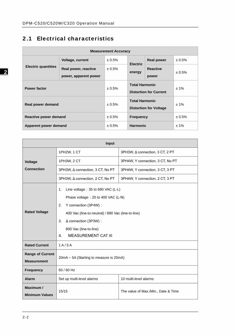
2.1 Electrical characteristics
Input
Voltage
Connection
1PH2W, 1 CT 3PH3W, Δ connection, 3 CT, 2 PT
1PH3W, 2 CT 3PH4W, Y connection, 3 CT, No PT
3PH3W, Δ connection, 3 CT, No PT 3PH4W, Y connection, 3 CT, 3 PT
3PH3W, Δ connection, 2 CT, No PT 3PH4W, Y connection, 2 CT, 3 PT
Rated Voltage
1. Line voltage:35 to 690 VAC (L-L)
Phase voltage:20 to 400 VAC (L-N)
2. Y connection (3P4W):
400 Vac (line-to-neutral) / 690 Vac (line-to-line)
3. Δ connection (3P3W):
600 Vac (line-to-line)
4. MEASUREMENT CAT III
Rated Current 1 A / 5 A
Range of Current
Measurement 20mA ~ 5A (Starting to measure is 20mA)
Frequency 50 / 60 Hz
Alarm Set up multi-level alarms 10 multi-level alarms
Maximum /
Minimum Values 15/15 The value of Max./Min., Date & Time
Measurement Accuracy
Electric quantities
Voltage, current ± 0.5% Electric
energy
Real power ± 0.5%
Real power, reactive
power, apparent power
± 0.5% Reactive
power ± 0.5%
Power factor ± 0.5% Total Harmonic
Distortion for Current ± 1%
Real power demand ± 0.5% Total Harmonic
Distortion for Voltage ± 1%
Reactive power demand ± 0.5% Frequency ± 0.5%
Apparent power demand ± 0.5% Harmonic ± 1%
Chapter 2 Speci f icat ions
2-3
2_
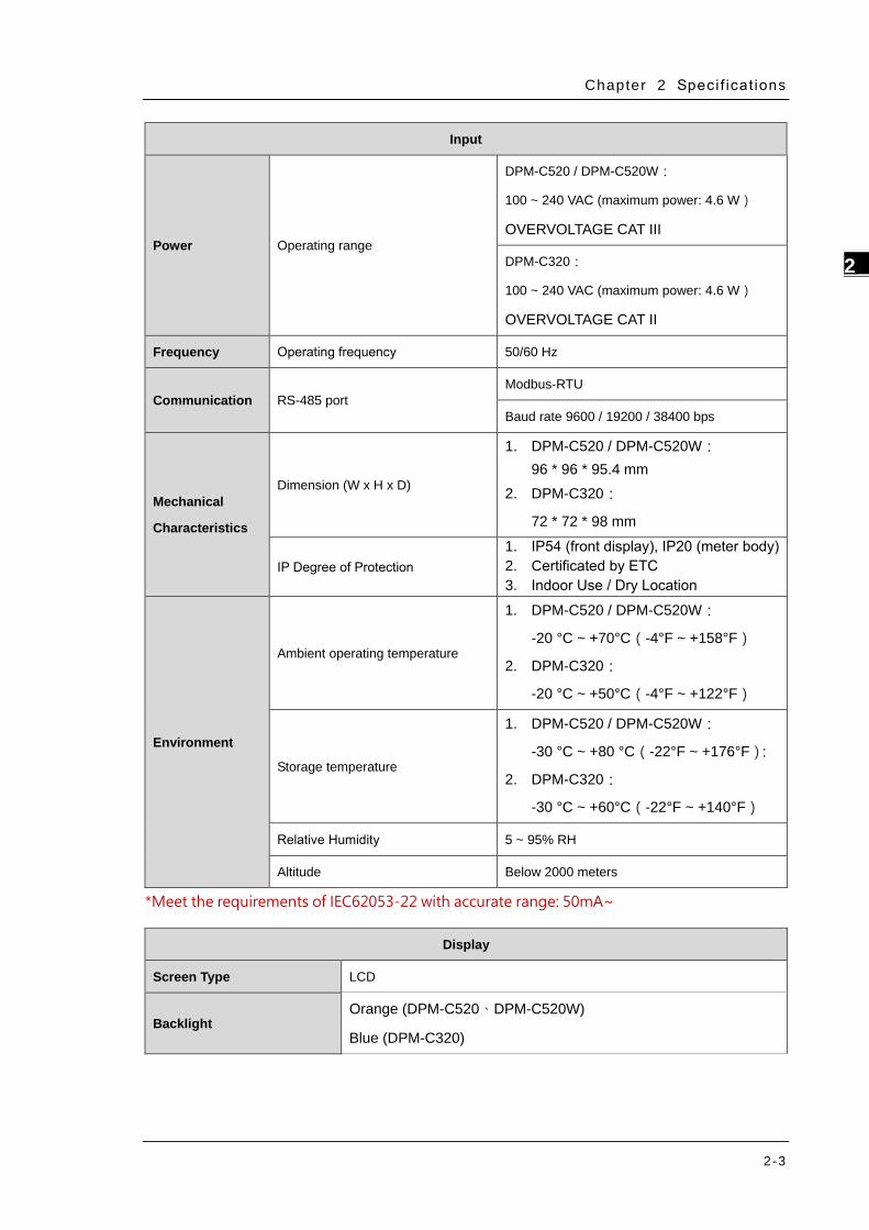
Input
Power Operating range
DPM-C520 / DPM-C520W:
100 ~ 240 VAC (maximum power: 4.6 W)
OVERVOLTAGE CAT III
DPM-C320:
100 ~ 240 VAC (maximum power: 4.6 W)
OVERVOLTAGE CAT II
Frequency Operating frequency 50/60 Hz
Communication RS-485 port Modbus-RTU
Baud rate 9600 / 19200 / 38400 bps
Mechanical
Characteristics
Dimension (W x H x D)
1. DPM-C520 / DPM-C520W: 96 * 96 * 95.4 mm
2. DPM-C320:
72 * 72 * 98 mm
IP Degree of Protection 1. IP54 (front display), IP20 (meter body) 2. Certificated by ETC 3. Indoor Use / Dry Location
Environment
Ambient operating temperature
1. DPM-C520 / DPM-C520W:
-20 °C ~ +70°C(-4°F ~ +158°F)
2. DPM-C320:
-20 °C ~ +50°C(-4°F ~ +122°F)
Storage temperature
1. DPM-C520 / DPM-C520W:
-30 °C ~ +80 °C(-22°F ~ +176°F):
2. DPM-C320:
-30 °C ~ +60°C(-22°F ~ +140°F)
Relative Humidity 5 ~ 95% RH
Altitude Below 2000 meters
*Meet the requirements of IEC62053-22 with accurate range: 50mA~
Display
Screen Type LCD
Backlight Orange (DPM-C520、DPM-C520W)
Blue (DPM-C320)
DPM-C520/C520W/C320 Operat ion Manual
2-4
_2
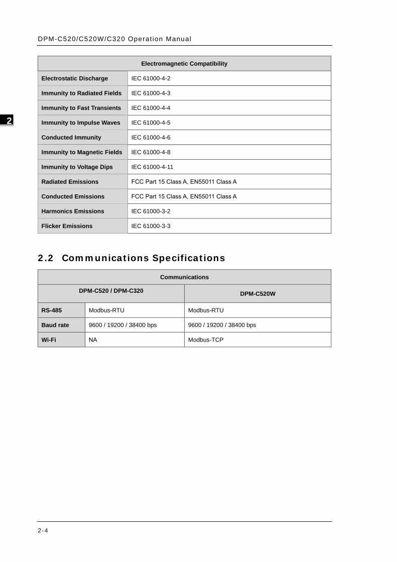
Electromagnetic Compatibility
Electrostatic Discharge IEC 61000-4-2
Immunity to Radiated Fields IEC 61000-4-3
Immunity to Fast Transients IEC 61000-4-4
Immunity to Impulse Waves IEC 61000-4-5
Conducted Immunity IEC 61000-4-6
Immunity to Magnetic Fields IEC 61000-4-8
Immunity to Voltage Dips IEC 61000-4-11
Radiated Emissions FCC Part 15 Class A, EN55011 Class A
Conducted Emissions FCC Part 15 Class A, EN55011 Class A
Harmonics Emissions IEC 61000-3-2
Flicker Emissions IEC 61000-3-3
2.2 Communications Specifications
Communications
DPM-C520 / DPM-C320 DPM-C520W
RS-485 Modbus-RTU Modbus-RTU
Baud rate 9600 / 19200 / 38400 bps 9600 / 19200 / 38400 bps
Wi-Fi NA Modbus-TCP
Chapter 2 Speci f icat ions
2-5
2_
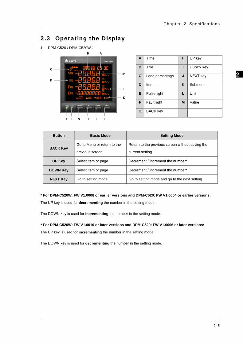
2.3 Operating the Display 1. DPM-C520 / DPM-C520W:
D
A
E F G H I J
B
L
MC
K
* For DPM-C520W: FW V1.0008 or earlier versions and DPM-C520: FW V1.0004 or earlier versions:
The UP key is used for decrementing the number in the setting mode.
The DOWN key is used for incrementing the number in the setting mode.
* For DPM-C520W: FW V1.0010 or later versions and DPM-C520: FW V1.0006 or later versions:
The UP key is used for incrementing the number in the setting mode.
The DOWN key is used for decrementing the number in the setting mode.
A Time H UP key
B Title I DOWN key
C Load percentage J NEXT key
D Item K Submenu
E Pulse light L Unit
F Fault light M Value
G BACK key
Button Basic Mode Setting Mode
BACK Key Go to Menu or return to the
previous screen
Return to the previous screen without saving the
current setting
UP Key Select item or page Decrement / Increment the number*
DOWN Key Select item or page Decrement / Increment the number*
NEXT Key Go to setting mode Go to setting mode and go to the next setting
DPM-C520/C520W/C320 Operat ion Manual
2-6
_2
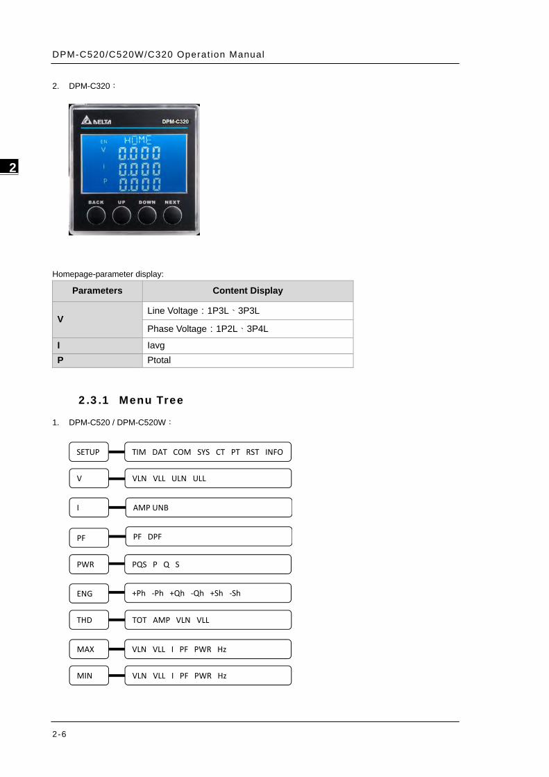
2. DPM-C320:
Homepage-parameter display:
Parameters Content Display
V Line Voltage:1P3L、3P3L
Phase Voltage:1P2L、3P4L
I Iavg P Ptotal
2.3.1 Menu Tree
1. DPM-C520 / DPM-C520W:
SETUP
V
I
PF
PWR
ENG
THD
MAX
MIN
TIM DAT COM SYS CT PT RST INFO
VLN VLL I PF PWR Hz
TOT AMP VLN VLL
+Ph ‐Ph +Qh ‐Qh +Sh ‐Sh
PQS P Q S
PF DPF
AMP UNB
VLN VLL ULN ULL
VLN VLL I PF PWR Hz
Chapter 2 Speci f icat ions
2-7
2_
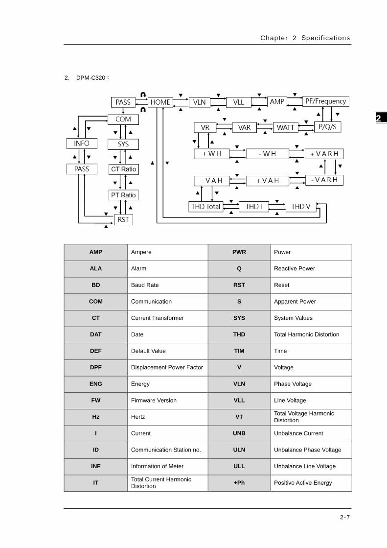
2. DPM-C320:
AMP Ampere PWR Power
ALA Alarm Q Reactive Power
BD Baud Rate RST Reset
COM Communication S Apparent Power
CT Current Transformer SYS System Values
DAT Date THD Total Harmonic Distortion
DEF Default Value TIM Time
DPF Displacement Power Factor V Voltage
ENG Energy VLN Phase Voltage
FW Firmware Version VLL Line Voltage
Hz Hertz VT Total Voltage Harmonic Distortion
I Current UNB Unbalance Current
ID Communication Station no. ULN Unbalance Phase Voltage
INF Information of Meter ULL Unbalance Line Voltage
IT Total Current Harmonic Distortion +Ph Positive Active Energy
DPM-C520/C520W/C320 Operat ion Manual
2-8
_2
MAX Maximum -Ph Negative Active Energy
MD Meter Model +Qh Positive Reactive Energy
MIN Minimum -Qh Negative Reactive Energy
P Active power +Sh Positive Apparent Power
PF Power Factor -Sh Negative Apparent Power
PQS Active Power, Reactive Power, Apparent Power 485 ON Disable Wi-Fi Function
PR Parity 485 OFF Enable Wi-Fi Function
PT Potential Transformer
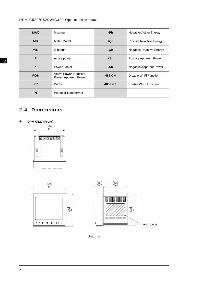
2.4 Dimensions
DPM-C520 (Front)
Unit: mm
Chapter 2 Speci f icat ions
2-9
2_
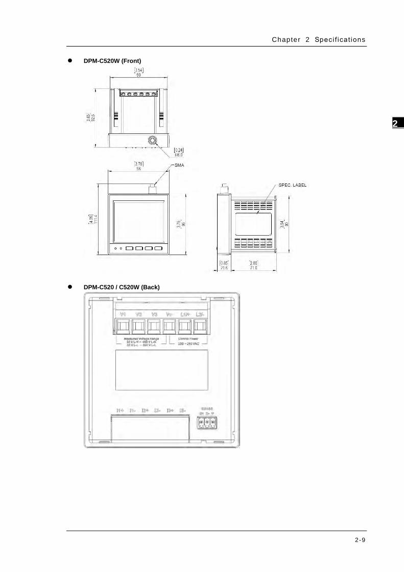
DPM-C520W (Front)
DPM-C520 / C520W (Back)
DPM-C520/C520W/C320 Operat ion Manual
2-10
_2
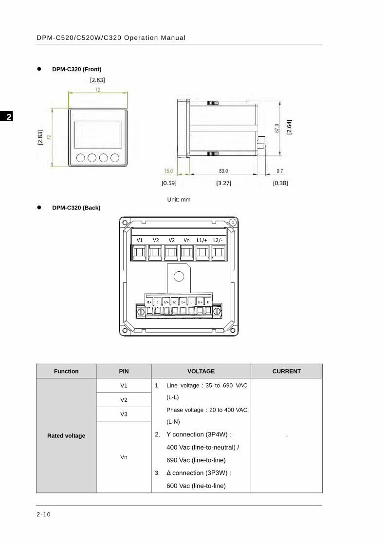
DPM-C320 (Front)
Unit: mm DPM-C320 (Back)
Function PIN VOLTAGE CURRENT
Rated voltage
V1 1. Line voltage:35 to 690 VAC
(L-L)
Phase voltage:20 to 400 VAC
(L-N)
2. Y connection (3P4W):
400 Vac (line-to-neutral) /
690 Vac (line-to-line)
3. Δ connection (3P3W):
600 Vac (line-to-line)
-
V2
V3
Vn
Chapter 2 Speci f icat ions
2-11
2_
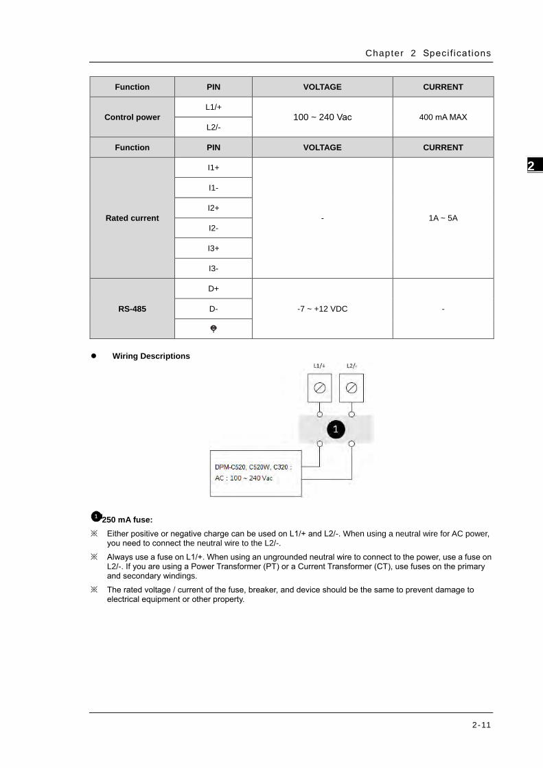
Function PIN VOLTAGE CURRENT
Control power L1/+
100 ~ 240 Vac 400 mA MAX L2/-
Function PIN VOLTAGE CURRENT
Rated current
I1+
- 1A ~ 5A
I1-
I2+
I2-
I3+
I3-
RS-485
D+
-7 ~ +12 VDC - D-
Wiring Descriptions
250 mA fuse: ※ Either positive or negative charge can be used on L1/+ and L2/-. When using a neutral wire for AC power,
you need to connect the neutral wire to the L2/-. ※ Always use a fuse on L1/+. When using an ungrounded neutral wire to connect to the power, use a fuse on
L2/-. If you are using a Power Transformer (PT) or a Current Transformer (CT), use fuses on the primary and secondary windings.
※ The rated voltage / current of the fuse, breaker, and device should be the same to prevent damage to electrical equipment or other property.

DPM-C520/C520W/C320 Operat ion Manual
2-12
_2
MEMO
3-1
3 3 Chapter 3 Installation
Table of Contents 3.1 Installation ......................................................................................... 3-2
3.1.1 Installation Environment .................................................................. 3-2
3.1.2 Installation Notes ............................................................................ 3-2
3.2 Basic Checks ....................................................................................... 3-5
3.3 Wiring ................................................................................................. 3-5
3.3.1 Wiring Diagrams ............................................................................. 3-5
3.3.2 Communication Characteristics ......................................................... 3-8
DPM-C520/C520W/C320 Operat ion Manual
3-2
_3 _3
3.1 Installation
3.1.1 Installation Environment
Keep the product in the shipping carton before installation. Store the product properly when it is not to be used
for an extended period of time to retain the warranty coverage. Some storage suggestions are listed below.
Store the power meter in a clean, dry, and controlled environment.
DPM-C520 / DPM-C520W store in an ambient temperature range of -30–80°C (-22–176°F).
DPM-C320 store in an ambient temperature range of -30–60°C (-22–140°F).
Store in a relative humidity range of 5–95%, non-condensing.
Do not store the product in a place subjected to corrosive gases or liquids.
Place the product on a solid and durable surface.
Do not mount the product near heat-radiating elements; or in a location subjected to corrosive gases,
liquids, airborne dust or metallic particles; or where it can be subjected to high levels of electromagnetic
radiation.
3.1.2 Installation Notes
Follow the instruction when installing the product to prevent equipment breakdown.
To increase the cooling efficiency, install the product with sufficient space between adjacent objects and
baffles and walls to prevent poor heat dissipation.
The maximum panel thickness should be 4.0 mm.

Chapter 3 Ins ta l lat ion
3-3
3_
Installation Steps
Step 1: Before installing the power meter, open the square hole on the metal plate.
Step 2: Push the meter into the hole and then slide the securing bracket in to the metal plate.
Step 3: Allow 50 mm (2 inches) of clearance at the back of the meter for heat dissipation.
DPM-C520/C520W/C320 Operat ion Manual
3-4
_3 _3
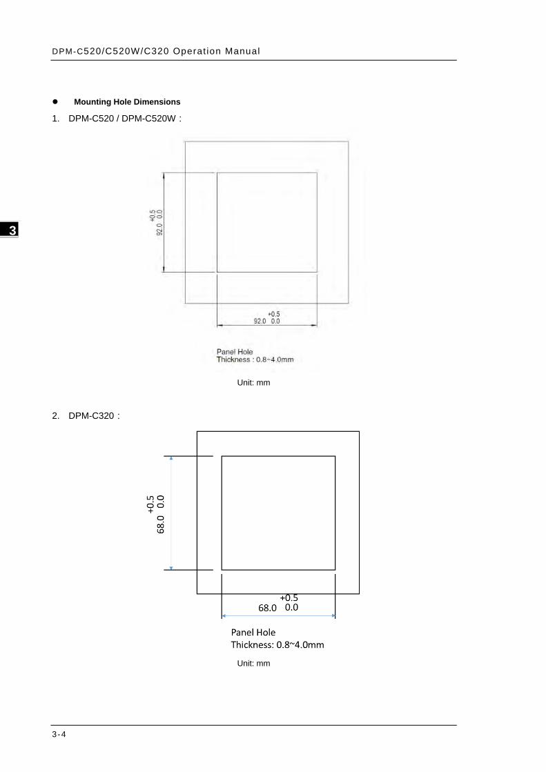
Mounting Hole Dimensions
1. DPM-C520 / DPM-C520W:
Unit: mm
2. DPM-C320:
Unit: mm

Chapter 3 Ins ta l lat ion
3-5
3_
3.2 Basic Checks
Items Contents
General Check
Regularly check for mounting looseness where the power meter and device are connected.
Prevent foreign objects, such as oil, water, or metal powder entering the device through the ventilation holes. Prevent drill shavings or other debris entering the power meter.
If the power meter is installed at a location with harmful gas or dust, prevent those materials from entering the power meter.
Pre-operation Check
(not supplied with power)
Insulate the connections at the wiring terminals. Communications wiring should be done properly to prevent abnormal operations. Check for the presence of conducive and flammable objects, such as screws or metal
pieces in the power meter. If electronic devices near to the power meter experience electromagnetic interference,
take steps to reduce the electromagnetic interference. Check for the correct voltage level for the power supplied to the power meter.
Pre-running Check
(supplied with power)
Check if the power indicator light is lit. Check if communication between every device is normal. If there is any abnormal response from the power meter, contact your distributor or our
customer service center.
3.3 Wiring
3.3.1 Wiring Diagrams
To avoid electric shock, do not change the wiring when the power is on.
Install a breaker switch on the power cord for the meter because there is no power switch on the power
meter.
When the measured voltage is higher than the rated specification for the device, it is necessary to use an
external potential transformer (PT).
When the measured current is higher than the rated specification for the device, it is necessary to use an
external current transformer (CT).
That could be installed in panel boards or switchgears shall comply with the following:
a) Always open or disconnect circuit from power-distribution system (or service) of building before
installing or servicing current transformers.
b) Restrict installation of current transformer in an area where it would block ventilation openings.
c) Restrict installation of current transformer in an area of breaker arc venting.
d) Not suitable for Class 2 wiring methods “and” Not intended for connection to Class 2 equipment.
e) Secure current transformer and route conductors so that they do not directly contact live terminals
or bus.
DPM-C520/C520W/C320 Operat ion Manual
3-6
_3 _3
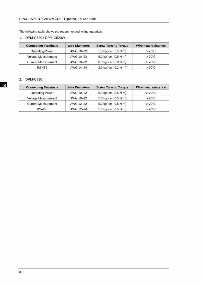
The following table shows the recommended wiring materials.
1. DPM-C520 / DPM-C520W:
2. DPM-C320:
Connecting Terminals Wire Diameters Screw Turning Torque Wire heat resistance
Operating Power AWG 10–22 5.0 kgf-cm (0.5 N·m) > 70°C
Voltage Measurement AWG 10–22 5.0 kgf-cm (0.5 N·m) > 70°C
Current Measurement AWG 10–22 8.0 kgf-cm (0.8 N·m) > 70°C
RS-485 AWG 14–24 2.0 kgf-cm (0.2 N·m) > 70°C
Connecting Terminals Wire Diameters Screw Turning Torque Wire heat resistance
Operating Power AWG 10–22 5.0 kgf-cm (0.5 N·m) > 70°C
Voltage Measurement AWG 10–22 5.0 kgf-cm (0.5 N·m) > 70°C
Current Measurement AWG 12–22 5.0 kgf-cm (0.5 N·m) > 70°C
RS-485 AWG 12–24 5.0 kgf-cm (0.5 N·m) > 70°C
Chapter 3 Ins ta l lat ion
3-7
3_
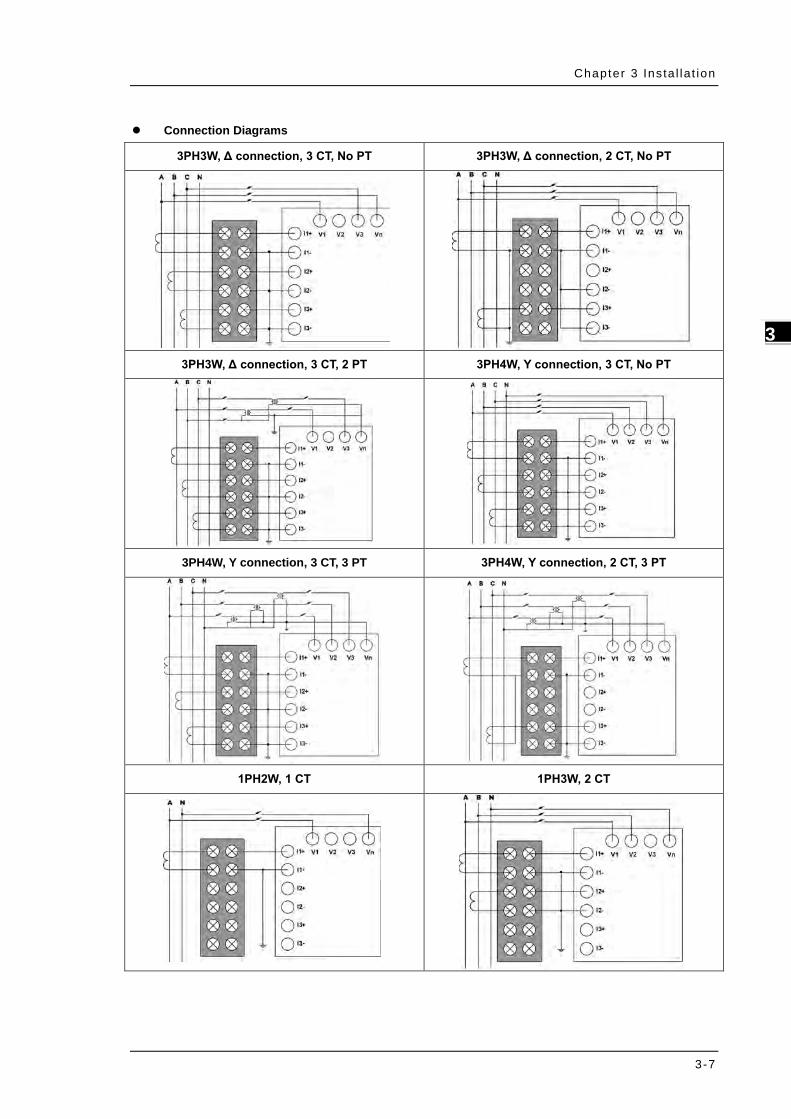
Connection Diagrams
3PH3W, Δ connection, 3 CT, No PT 3PH3W, Δ connection, 2 CT, No PT
3PH3W, Δ connection, 3 CT, 2 PT 3PH4W, Y connection, 3 CT, No PT
3PH4W, Y connection, 3 CT, 3 PT 3PH4W, Y connection, 2 CT, 3 PT
1PH2W, 1 CT 1PH3W, 2 CT

DPM-C520/C520W/C320 Operat ion Manual
3-8
_3 _3
The following table lists the symbols used in the diagram.
Symbol
Description Grounding Current transformer Terminal block Voltage transformer Fuse
Rated value:
1. Y (3p4w):400/690 Vac
2. ∆ (3p3w):600 Vac
3. Single Phase:240/480 Vac
3.3.2 Communication Characteristics
Communications Specifications:
Max. Communication
Distance 1200 m Baud Rate 9600, 19200, 38400 bps
Max. Connection
Number 32 Data Length 8-bits
Communication
Protocols Modbus RTU Parity None, Odd, Even
Function Code 03, 06, 10 Stop Bits 1
Chapter 3 Ins ta l lat ion
3-9
3_
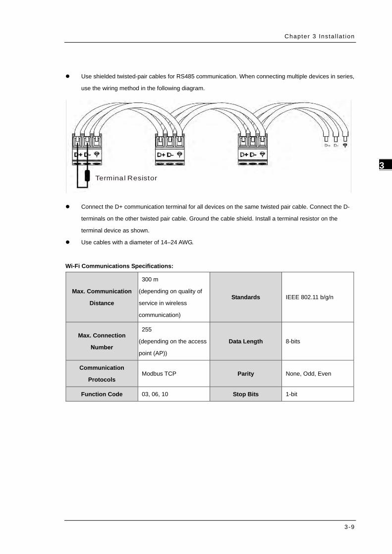
Use shielded twisted-pair cables for RS485 communication. When connecting multiple devices in series,
use the wiring method in the following diagram.
Terminal Resistor
Connect the D+ communication terminal for all devices on the same twisted pair cable. Connect the D-
terminals on the other twisted pair cable. Ground the cable shield. Install a terminal resistor on the
terminal device as shown.
Use cables with a diameter of 14–24 AWG.
Wi-Fi Communications Specifications:
Max. Communication
Distance
300 m
(depending on quality of
service in wireless
communication)
Standards IEEE 802.11 b/g/n
Max. Connection
Number
255
(depending on the access
point (AP))
Data Length 8-bits
Communication
Protocols Modbus TCP Parity None, Odd, Even
Function Code 03, 06, 10 Stop Bits 1-bit

DPM-C520/C520W/C320 Operat ion Manual
3-10
_3 _3
MEMO

4-1
4 Chapter 4 Operation Table of Contents
4.1 General Operation ............................................................................... 4-3
4.1.1 Setting Menu.................................................................................. 4-3
4.2 DPM-C520 / DPM-C520W Setups ......................................................... 4-4
4.2.1 Unlock the Setting .......................................................................... 4-4
4.2.2 Time Setup (TIM) ........................................................................... 4-4
4.2.3 Date Setup (DAT) ........................................................................... 4-5
4.2.4 Communication Setup (COM) ............................................................ 4-5
4.2.5 System Setup (SYS) ........................................................................ 4-6
4.2.6 Current Transformer Setup (CT) ........................................................ 4-6
4.2.7 Potential Transformer Setup (PT)....................................................... 4-7
4.2.8 Reset Setup (RST) .......................................................................... 4-8
4.2.9 Meter Information (INF) ................................................................... 4-8
4.2.10 Wi-Fi Setup (485 ON/OFF) only available for DPM-C520W ................... 4-8
4.2.11 Alarm Setup ................................................................................. 4-9
4.2.12 Parameter Grouping Setup ............................................................. 4-9
4.3 DPM-C320 Setups .............................................................................. 4-11
4.3.1 Communication Setup (COM) .......................................................... 4-11
4.3.2 System Setup (SYS) ...................................................................... 4-11
4.3.3 Current Transformer Setup (CT) ...................................................... 4-11
4.3.4 Potential Transformer Setup (PT)..................................................... 4-12
4.3.5 Reset Setup (RST) ........................................................................ 4-12
4.3.6 Meter Information (INF) ................................................................. 4-13
4.3.7 Parameter Grouping Setup ............................................................. 4-13
4.3.8 Language .................................................................................... 4-14
4.4 Wi-Fi Setup (only available for DPM-C520W) .................................... 4-15
4.4.1 Wi-Fi Specification ........................................................................ 4-15
4.4.2 Wireless Access Point (AP) Setup .................................................... 4-15
4.4.3 Advanced Wi-Fi Setup ................................................................... 4-20
4
DPM-C520/C520W/C320 Operat ion Manual
4-2
_4
4.5 Power Analysis Values ...................................................................... 4-27
4.5.1 Total Harmonic Distortion Measurement ........................................... 4-27
Chapter 4 Operat ion
4-3
4_
4.1 General Operation
1. Use UP and DOWN keys to switch among setting pages.
2. You can go back to HOME page by using BACK or INDEX (DPM-C520 / DPM-C520W) keys.
Note 1: use BACK key in HOME page to enter the setting page.
4.1.1 Setting Menu
HOME page (HOME):
Voltage values measured by the power meter, including total voltage (VT), total current (IT), total power
(PT), total positive active energy (ET). (DPM-C520 / DPM-C520W)
Voltage values measured by the power meter, including total voltage (V), total current (I), total power (P).
(DPM-C320)
Phase voltage (VLN): phase voltage values measured by the power meter, including phase A voltage
(AN), phase B voltage (BN), phase C voltage (CN ) and average phase voltage (T).
Line voltage (VLL): line voltage values measured by the power meter, including A-B line voltage (AB),
B-C line voltage (BC), C-A line voltage (CA), and average line voltage (T).
Electric current page (AMP): electric current measured by the power meter, including phase A current
(A), phase B current (B), phase C current (C) and average current (T).
Power factor page (PF): power factors measured by the power meter, including power factors of phase A
(A), phase B (B), phase C(C), total power factor (T) and frequency (Hz).
Active power, reactive power, and apparent power page (PQS): values measured by the power meter,
including total active power (PT), total reactive power (QT), and total apparent power (ST).
Active power page (WATT): active power value measured by the power meter, including active power of
phase A (A), phase B (B), phase C (C) and total active power (T).
Reactive power page (VAR): reactive power value measured by the power meter, including reactive
power of phase A (A), phase B (B), phase C (C) and total reactive power (T).
Apparent power page (VA): apparent power value measured by the power meter, including apparent
power of phase A (A), phase B (B), phase C (C) and total apparent power (T).
Positive active energy page (+WH): positive active energy measured by the power meter, including
positive active energy (PH).
Reversed active energy page (-WH): reversed active energy measured by the power meter, including
reversed active energy (PH).
Positive reactive energy page (+VARH): positive reactive energy measured by the power meter, including
positive reactive energy (QH).
Reversed reactive energy page (-VARH): reversed reactive energy measured by the power meter,
including reserved reactive energy (QH).
Positive apparent energy page (+VAH): positive apparent energy measured by the power meter,
including positive apparent energy (SH).
DPM-C520/C520W/C320 Operat ion Manual
4-4
_4
Reversed apparent energy page (-VAH): reversed apparent energy measured by the power meter,
including reserved apparent energy (SH).
Total harmonic distortion of current page (THD I): current harmonic distortion measured by the power
meter, including harmonic distortion for phase A current (A), harmonic distortion for phase B current (B),
harmonic distortion for phase C current (C) and total harmonic distortion for current (T).
Total harmonic distortion of voltage page (THD V): voltage harmonic distortion measured by the power
meter, including harmonic distortion for phase A voltage (A), harmonic distortion for phase B voltage (B),
harmonic distortion for phase C voltage (C) and total harmonic distortion for voltage (T).
4.2 DPM-C520 / DPM-C520W Setups
4.2.1 Unlock the Setting
Steps:
1. Press BACK key to enter the setting page.
2. Press UP and DOWN keys at the same time for 5 seconds to unlock the setting.
3. When you see the setting option TIM & DAT, it means you have unlocked the setting page.
Note 1: press BACK key to leave the setting page and go to HOME page.
4.2.2 Time Setup (TIM)
Time: Present power meter time; the time format includes the hour and minute.
Steps:
1. Press BACK key to enter the setting page.
2. Press UP and DOWN keys at the same time for 5 seconds to unlock the setting.
3. Press NEXT key to see the setting option TIM & DAT.
4. Press UP key to enter the time (TIM) setting page.
5. When the option (HH) starts blinking, you can use UP and DOWN keys to select the number of the
hour.
6. Press NEXT key to confirm the setting.
7. When the option (MM) starts blinking, you can use UP and DOWN keys to select the number of the
minute.
8. Press NEXT key to confirm the setting.
Note: You can go back to the previous setting item by pressing BACK key anytime, whether you have
completed or canceled the setting.

Chapter 4 Operat ion
4-5
4_
4.2.3 Date Setup (DAT)
Date: Present power meter date; the date format includes the last two digits of the year, month, date and
day.
Steps:
1. Press BACK key to enter the setting page.
2. Press UP and DOWN keys at the same time for 5 seconds to unlock the setting.
3. Press NEXT key to see the setting option TIM & DAT.
4. Press DOWN key to enter the date (DAT) setting page.
5. When the option (YY) starts blinking, you can use UP and DOWN keys to select the number of the
year.
6. Press NEXT key to confirm the setting.
7. When the option (MM) starts blinking, you can use UP and DOWN keys to select the number of the
month.
8. Press NEXT key to confirm the setting.
9. When the option (DD) starts blinking, you can use UP and DOWN keys to select the number of the
date.
10. Press NEXT key to confirm the setting.
Note: You can go back to the previous setting item by pressing BACK key anytime, whether you have
completed or canceled the setting.
4.2.4 Communication Setup (COM)
Address (ID): device ID; its address setting range is 1-254 (default: 1).
Baud Rate (BR): transmission speed; the setting options are 9600 kbps (default), 19200 and 38400 bps.
Parity setting (PA): odd and even checking bit for communication; the setting options are None (8n1),
Even (8E1), and Odd (8o1); default: None (8n1).
Steps:
1. Press BACK key to enter the setting page.
2. Press UP and DOWN keys at the same time for 5 seconds to unlock the setting.
3. Press NEXT key to see the setting option COM & SYS.
4. Press UP key to enter the communication (COM) setting page.
5. Use UP and DOWN keys to select the device ID. (one digit at a time; hundreds digit tens digit
units digit )
6. Press NEXT key to confirm the setting and start to set the next device ID.
7. Repeat steps 5-6 till you complete the settings of the 3 digit device ID. Press NEXT key to set up the
baud rate.
8. When the option starts blinking, you can use UP and DOWN keys to select the baud rate you need.

DPM-C520/C520W/C320 Operat ion Manual
4-6
_4
9. Press NEXT key to confirm the setting and start to set the next setting, parity.
10. When the option starts blinking, you can use UP and DOWN keys to select the parity you need.
11. Press NEXT key to confirm the setting.
Note: You can go back to the previous setting item by pressing BACK key anytime, whether you have
completed or canceled the setting.
4.2.5 System Setup (SYS)
Wiring methods (WR): options are one-phase two-wire (1PH2W), one-phase three-wire (1PH3W),
three-phase three-wire (3PH3W), and three-phase four-wire (3PH4W); default: three-phase four-wire.
Number of current transformers (CT): options are 1, 2 and 3; default: 3.
Number of potential transformers (PT): options are 0, 2 and 3; default: 3.
Steps:
1. Press BACK key to enter the setting page.
2. Press UP and DOWN keys at the same time for 5 seconds to unlock the setting.
3. Press NEXT key to see the setting option COM & SYS.
4. Press DOWN key to enter the system (SYS) setting page.
5. Use UP and DOWN keys to select the wiring method.
6. Press NEXT key to confirm the setting and start to set the next setting, the number of current
transformers (CT).
7. When the option starts blinking, you can use UP and DOWN keys to select the number of current
transformers you need.
8. Press NEXT key to confirm the setting and start to set the next setting, the number of potential
transformers (PT).
9. When the option starts blinking, you can use UP and DOWN keys to select the number of potential
transformers you need.
10. Press NEXT key to confirm the setting.
Note: You can go back to the previous setting item by pressing BACK key anytime, whether you have
completed or canceled the setting.
4.2.6 Current Transformer Setup (CT)
Ampere for the primary-side current transformer: ranging from 1 to 9999 A; default: 5 A.
Ampere for the secondary-side current transformer: options are 1 and 5 A; default 5 A.
Steps:
1. Press BACK key to enter the setting page.
2. Press UP and DOWN keys at the same time for 5 seconds to unlock the setting.
3. Press NEXT key to see the setting option CT & PT.
Chapter 4 Operat ion
4-7
4_
4. Press UP key to enter the current transformer (CT) setting page.
5. Use UP and DOWN keys to select the number for the primary-side current transformer.
6. Press NEXT key to confirm the setting and start to set the next number for the primary-side current
transformer.
7. Repeat steps 5-6 till you complete the settings of the 4 digit number for the primary-side current
transformer. Press NEXT key to set up the secondary-side current transformer.
8. When the option starts blinking, you can use UP and DOWN keys to select the number of the
secondary-side current transformer.
9. Press NEXT key to confirm the setting.
Note: You can go back to the previous setting item by pressing BACK key anytime, whether you have
completed or canceled the setting.
4.2.7 Potential Transformer Setup (PT)
Voltage for the primary-side potential transformer: ranging from 1 to 9999 V; default: 1 V.
Voltage for the secondary-side potential transformer: ranging from 1 to 9999 V; default: 1 V.
Steps:
1. Press BACK key to enter the setting page.
2. Press UP and DOWN keys at the same time for 5 seconds to unlock the setting.
3. Press NEXT key to see the setting option CT & PT.
4. Press DOWN key to enter the potential transformer (PT) setting page.
5. Use UP and DOWN keys to select the number for the primary-side potential transformer.
6. Press NEXT key to confirm the setting and start to set the next number for the primary-side
potential transformer.
7. Repeat steps 5-6 till you complete the settings of the 5 digit number for the primary-side potential
transformer. Press NEXT key to set up the secondary-side potential transformer.
8. When the option starts blinking, you can use UP and DOWN keys to select the number of the
secondary-side potential transformer.
9. Press NEXT key to confirm the setting and start to set the next number for the primary-side
potential transformer.
10. Repeat steps 5-6 till you complete the settings of the 4 digit number for the primary-side potential
transformer.
11. Press NEXT key to confirm the setting.
Note: You can go back to the previous setting item by pressing BACK key anytime, whether you have
completed or canceled the setting.
DPM-C520/C520W/C320 Operat ion Manual
4-8
_4
4.2.8 Reset Setup (RST)
Default (DEF): Restore all the settings back to the defaults (including wireless settings).
Energy (ENG): Reset all the accumulated energy values and automatic energy values.
MaxMin (MM): Clear all maximum values and minimum value logs.
Alarm (ALA): Clear all the detected alarm logs.
Steps:
1. Press BACK key to enter the setting page.
2. Press UP and DOWN keys at the same time for 5 seconds to unlock the setting.
3. Press NEXT key to see the setting option RST & INF.
4. Press UP key to enter the reset (RST) setting page.
5. Use UP and DOWN keys to select the reset options (DEF, ENG, MM and ALA).
6. Press NEXT key to confirm the setting.
Note: You can go back to the previous setting item by pressing BACK key anytime, whether you have
completed or canceled the setting.
4.2.9 Meter Information (INF)
Model Name (MD): C520 or C520W
Firmware Version (FW): 1.XXXX
Date (DT): Firmware release date YYYY.MM.DD
Steps:
1. Press BACK key to enter the setting page.
2. Press UP and DOWN keys at the same time for 5 seconds to unlock the setting.
3. Press NEXT key to see the setting option RST & INF.
4. Press DOWN key to enter see the information (INF) page.
Note: You can go back to the previous setting item by pressing BACK key anytime, whether you have
completed or canceled the setting.
4.2.10 Wi-Fi Setup (485 ON/OFF) only available for DPM-C520W
Wi-Fi: When 485 is ON, Wi-Fi function is disabled. When 485 is OFF, Wi-Fi function is enabled.
Steps:
1. Press BACK key to enter the setting page.
2. See 485 ON or 485 OFF on the screen.
3. Press NEXT key for 3 seconds to switch from 485 ON to 485 OFF.
Chapter 4 Operat ion
4-9
4_
4.2.11 Alarm Setup
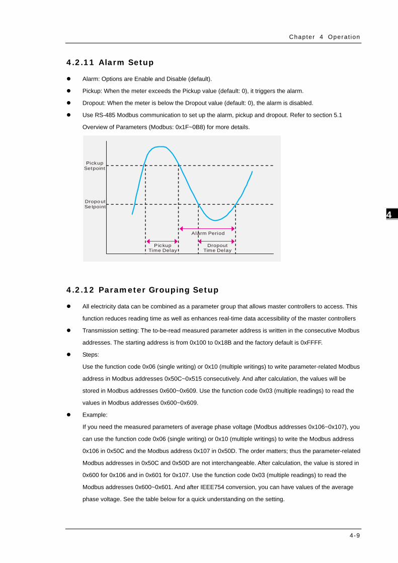
Alarm: Options are Enable and Disable (default).
Pickup: When the meter exceeds the Pickup value (default: 0), it triggers the alarm.
Dropout: When the meter is below the Dropout value (default: 0), the alarm is disabled.
Use RS-485 Modbus communication to set up the alarm, pickup and dropout. Refer to section 5.1
Overview of Parameters (Modbus: 0x1F~0B8) for more details.
PickupSetpoint
DropoutSe tpoint
Pickup Time Delay
Alarm Period
Dropout Time Delay
4.2.12 Parameter Grouping Setup
All electricity data can be combined as a parameter group that allows master controllers to access. This
function reduces reading time as well as enhances real-time data accessibility of the master controllers
Transmission setting: The to-be-read measured parameter address is written in the consecutive Modbus
addresses. The starting address is from 0x100 to 0x18B and the factory default is 0xFFFF.
Steps:
Use the function code 0x06 (single writing) or 0x10 (multiple writings) to write parameter-related Modbus
address in Modbus addresses 0x50C~0x515 consecutively. And after calculation, the values will be
stored in Modbus addresses 0x600~0x609. Use the function code 0x03 (multiple readings) to read the
values in Modbus addresses 0x600~0x609.
Example:
If you need the measured parameters of average phase voltage (Modbus addresses 0x106~0x107), you
can use the function code 0x06 (single writing) or 0x10 (multiple writings) to write the Modbus address
0x106 in 0x50C and the Modbus address 0x107 in 0x50D. The order matters; thus the parameter-related
Modbus addresses in 0x50C and 0x50D are not interchangeable. After calculation, the value is stored in
0x600 for 0x106 and in 0x601 for 0x107. Use the function code 0x03 (multiple readings) to read the
Modbus addresses 0x600~0x601. And after IEEE754 conversion, you can have values of the average
phase voltage. See the table below for a quick understanding on the setting.
DPM-C520/C520W/C320 Operat ion Manual
4-10
_4
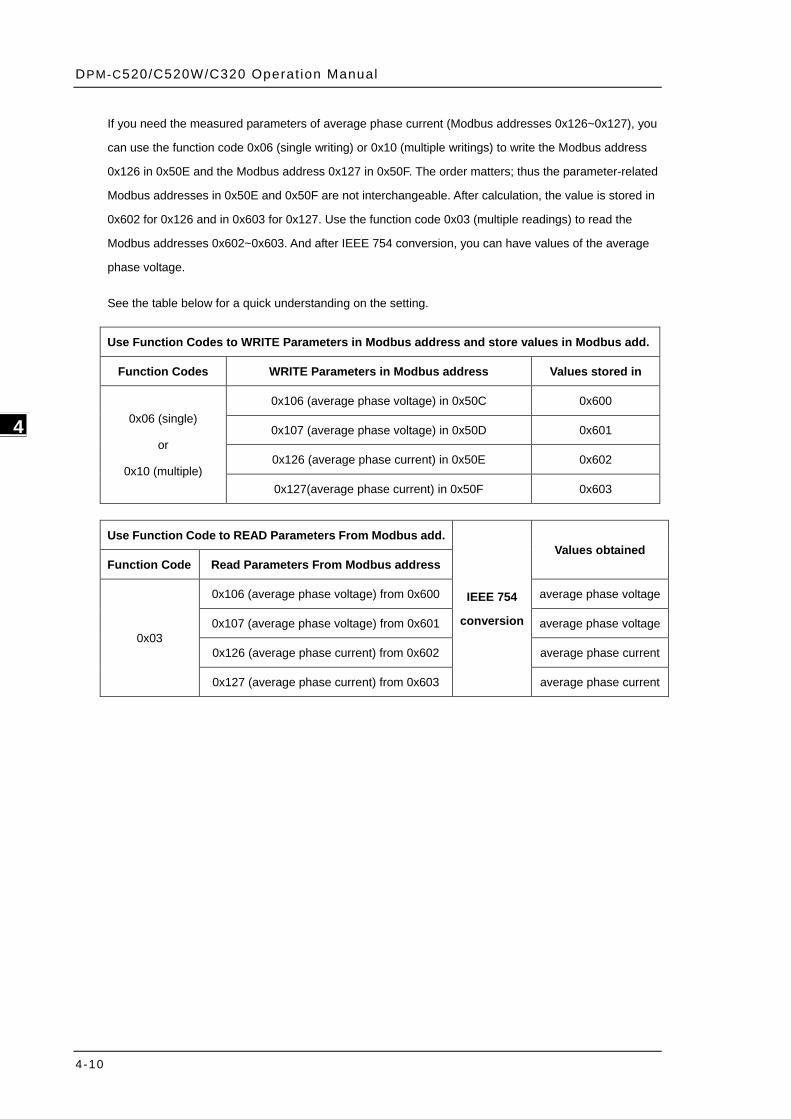
If you need the measured parameters of average phase current (Modbus addresses 0x126~0x127), you
can use the function code 0x06 (single writing) or 0x10 (multiple writings) to write the Modbus address
0x126 in 0x50E and the Modbus address 0x127 in 0x50F. The order matters; thus the parameter-related
Modbus addresses in 0x50E and 0x50F are not interchangeable. After calculation, the value is stored in
0x602 for 0x126 and in 0x603 for 0x127. Use the function code 0x03 (multiple readings) to read the
Modbus addresses 0x602~0x603. And after IEEE 754 conversion, you can have values of the average
phase voltage.
See the table below for a quick understanding on the setting.
Use Function Codes to WRITE Parameters in Modbus address and store values in Modbus add.
Function Codes WRITE Parameters in Modbus address Values stored in
0x06 (single)
or
0x10 (multiple)
0x106 (average phase voltage) in 0x50C 0x600
0x107 (average phase voltage) in 0x50D 0x601
0x126 (average phase current) in 0x50E 0x602
0x127(average phase current) in 0x50F 0x603
Use Function Code to READ Parameters From Modbus add.
IEEE 754
conversion
Values obtained Function Code Read Parameters From Modbus address
0x03
0x106 (average phase voltage) from 0x600 average phase voltage
0x107 (average phase voltage) from 0x601 average phase voltage
0x126 (average phase current) from 0x602 average phase current
0x127 (average phase current) from 0x603 average phase current
Chapter 4 Operat ion
4-11
4_
4.3 DPM-C320 Setups
4.3.1 Communication Setup (COM)
Address (ID): device ID; its address setting range is 1-254 (default: 1).
Baud Rate (BR): transmission speed; the setting options are 9600 kbps (default), 19200 and 38400 bps.
Parity setting (PA): odd and even checking bit for communication; the setting options are None (8n1),
Even (8E1), and Odd (8o1); default: None (8n1).
Steps:
1. Press BACK key then input password to see the setting option COM.
2. Use UP and DOWN keys to select the device ID. (one digit at a time; hundreds digit tens digit
units digit )
3. Press NEXT key to confirm the setting and start to set the next device ID.
4. Repeat steps 5-6 till you complete the settings of the 3 digit device ID. Press NEXT key to set up the
baud rate.
5. When the option starts blinking, you can use UP and DOWN keys to select the baud rate you need.
6. Press NEXT key to confirm the setting and start to set the next setting.
7. Press NEXT key to confirm the setting.
Note: You can go back to the previous setting item by pressing BACK key anytime, whether you have
completed or canceled the setting.
4.3.2 System Setup (SYS)
Wiring methods (WR): options are one-phase two-wire (1PH2W), one-phase three-wire (1PH3W),
three-phase three-wire (3PH3W), and three-phase four-wire (3PH4W); default: three-phase four-wire.
Number of current transformers (CT): options are 1, 2 and 3; default: 3.
Number of potential transformers (PT): options are 0, 2 and 3; default: 3.
Steps:
1. Press BACK key then input password to see the setting option COM.
2. Use UP and DOWN keys to enter the system (SYS) setting page.
3. Use UP and DOWN keys to select the wiring method.
4. Press NEXT key to confirm the setting.
Note: You can go back to the previous setting item by pressing BACK key anytime, whether you have
completed or canceled the setting.
4.3.3 Current Transformer Setup (CT)
Ampere for the primary-side current transformer: ranging from 1 to 9999 A; default: 5 A.
Ampere for the secondary-side current transformer: options are 1 and 5 A; default 5 A.
DPM-C520/C520W/C320 Operat ion Manual
4-12
_4
Steps:
1. Press BACK key then input password to see the setting page.
2. Use UP and DOWN keys to enter the system (CT) setting page.
3. Use UP and DOWN keys to select the number for the primary-side current transformer.
4. When the option starts blinking, you can use UP and DOWN keys to select the number of the
secondary-side current transformer.
5. Press NEXT key to confirm the setting.
Note: You can go back to the previous setting item by pressing BACK key anytime, whether you have
completed or canceled the setting.
4.3.4 Potential Transformer Setup (PT)
Voltage for the primary-side potential transformer: ranging from 1 to 9999 V; default: 1 V.
Voltage for the secondary-side potential transformer: ranging from 1 to 9999 V; default: 1 V.
Steps:
1. Press BACK key then input password to see the setting page.
2. Press UP and DOWN keys to enter the potential transformer (PT) setting page.
3. Use UP and DOWN keys to select the number for the primary-side potential transformer.
4. Press NEXT key to confirm the setting and start to set the next number for the primary-side
potential transformer.
5. When the option starts blinking, you can use UP and DOWN keys to select the number of the
secondary-side potential transformer.
6. Press NEXT key to confirm the setting.
Note: You can go back to the previous setting item by pressing BACK key anytime, whether you have
completed or canceled the setting.
4.3.5 Reset Setup (RST)
Default (dEF): Restore all the settings back to the defaults (including wireless settings).
Energy (PH): Reset all the accumulated energy values and automatic energy values.
Alarm (ALA): Clear all the detected alarm logs.
Steps:
1. Press BACK key then input password to see the setting page.
2. Press UP and DOWN keys to see the setting option RST.
3. Use UP and DOWN keys to select the reset options (dEF, PH and ALA).
4. Press NEXT key to confirm the setting.
Note: You can go back to the previous setting item by pressing BACK key anytime, whether you have
completed or canceled the setting.
Chapter 4 Operat ion
4-13
4_
4.3.6 Meter Information (INF)
Model Name (MD): C320
Firmware Version (FW): 1.XXXX
Date (DT): Firmware release date MM.DD
Steps:
1. Press BACK key then input password to see the setting page.
2. Press UP and DOWN keys to see the setting option INF.
Note: You can go back to the previous setting item by pressing BACK key anytime, whether you have
completed or canceled the setting.
4.3.7 Parameter Grouping Setup
All electricity data can be combined as a parameter group that allows master controllers to access. This
function reduces reading time as well as enhances real-time data accessibility of the master controllers
Transmission setting: The to-be-read measured parameter address is written in the consecutive Modbus
addresses. The starting address is from 0x100 to 0x18B and the factory default is 0xFFFF.
Steps:
Use the function code 0x06 (single writing) or 0x10 (multiple writings) to write parameter-related Modbus
address in Modbus addresses 0x50C~0x515 consecutively. And after calculation, the values will be
stored in Modbus addresses 0x600~0x609. Use the function code 0x03 (multiple readings) to read the
values in Modbus addresses 0x600~0x609.
Example:
If you need the measured parameters of average phase voltage (Modbus addresses 0x106~0x107), you
can use the function code 0x06 (single writing) or 0x10 (multiple writings) to write the Modbus address
0x106 in 0x50C and the Modbus address 0x107 in 0x50D. The order matters; thus the parameter-related
Modbus addresses in 0x50C and 0x50D are not interchangeable. After calculation, the value is stored in
0x600 for 0x106 and in 0x601 for 0x107. Use the function code 0x03 (multiple readings) to read the
Modbus addresses 0x600~0x601. And after IEEE754 conversion, you can have values of the average
phase voltage. See the table below for a quick understanding on the setting.
If you need the measured parameters of average phase current (Modbus addresses 0x126~0x127), you
can use the function code 0x06 (single writing) or 0x10 (multiple writings) to write the Modbus address
0x126 in 0x50E and the Modbus address 0x127 in 0x50F. The order matters; thus the parameter-related
Modbus addresses in 0x50E and 0x50F are not interchangeable. After calculation, the value is stored in
0x602 for 0x126 and in 0x603 for 0x127. Use the function code 0x03 (multiple readings) to read the
Modbus addresses 0x602~0x603. And after IEEE 754 conversion, you can have values of the average
phase voltage.
DPM-C520/C520W/C320 Operat ion Manual
4-14
_4
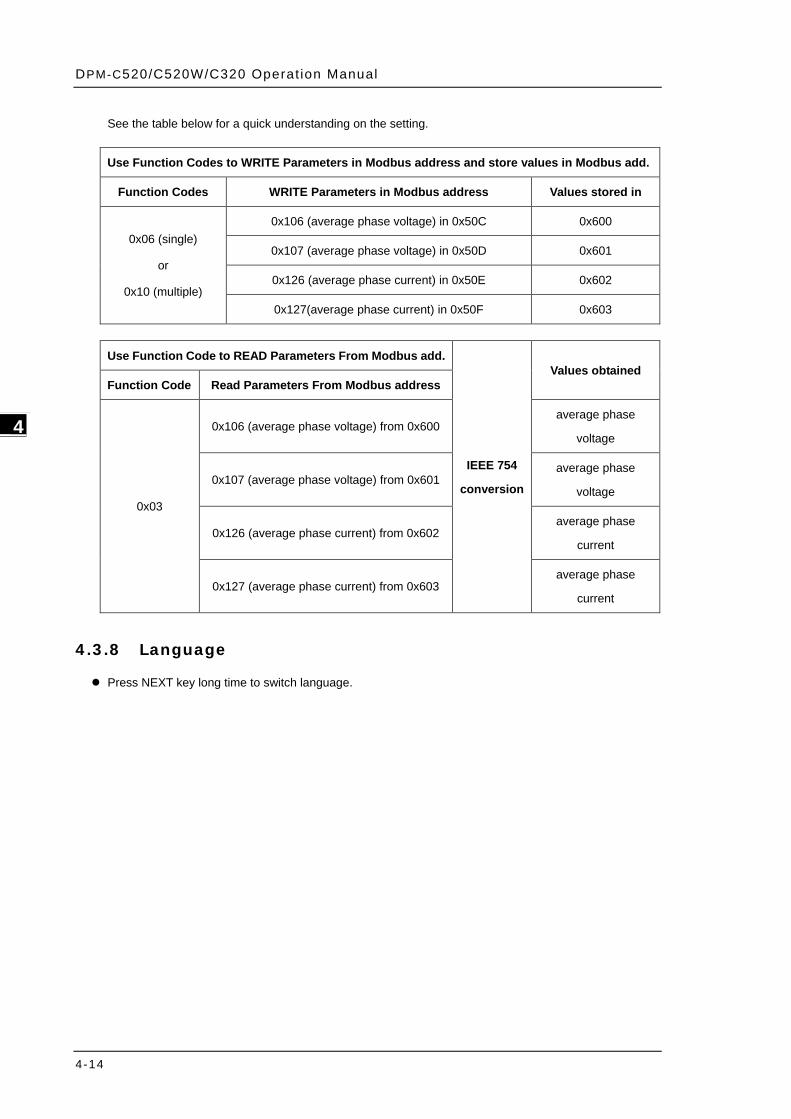
See the table below for a quick understanding on the setting.
Use Function Codes to WRITE Parameters in Modbus address and store values in Modbus add.
Function Codes WRITE Parameters in Modbus address Values stored in
0x06 (single)
or
0x10 (multiple)
0x106 (average phase voltage) in 0x50C 0x600
0x107 (average phase voltage) in 0x50D 0x601
0x126 (average phase current) in 0x50E 0x602
0x127(average phase current) in 0x50F 0x603
Use Function Code to READ Parameters From Modbus add.
IEEE 754
conversion
Values obtained Function Code Read Parameters From Modbus address
0x03
0x106 (average phase voltage) from 0x600 average phase
voltage
0x107 (average phase voltage) from 0x601 average phase
voltage
0x126 (average phase current) from 0x602 average phase
current
0x127 (average phase current) from 0x603 average phase
current
4.3.8 Language
Press NEXT key long time to switch language.
Chapter 4 Operat ion
4-15
4_
4.4 Wi-Fi Setup (only available for DPM-C520W)
4.4.1 Wi-Fi Specification
Max. Communication
Distance 300 m Standards IEEE 802.11 b/g/n
Function code 03, 06, 10 Data Length 8-bits
Communication
Protocols Modbus TCP
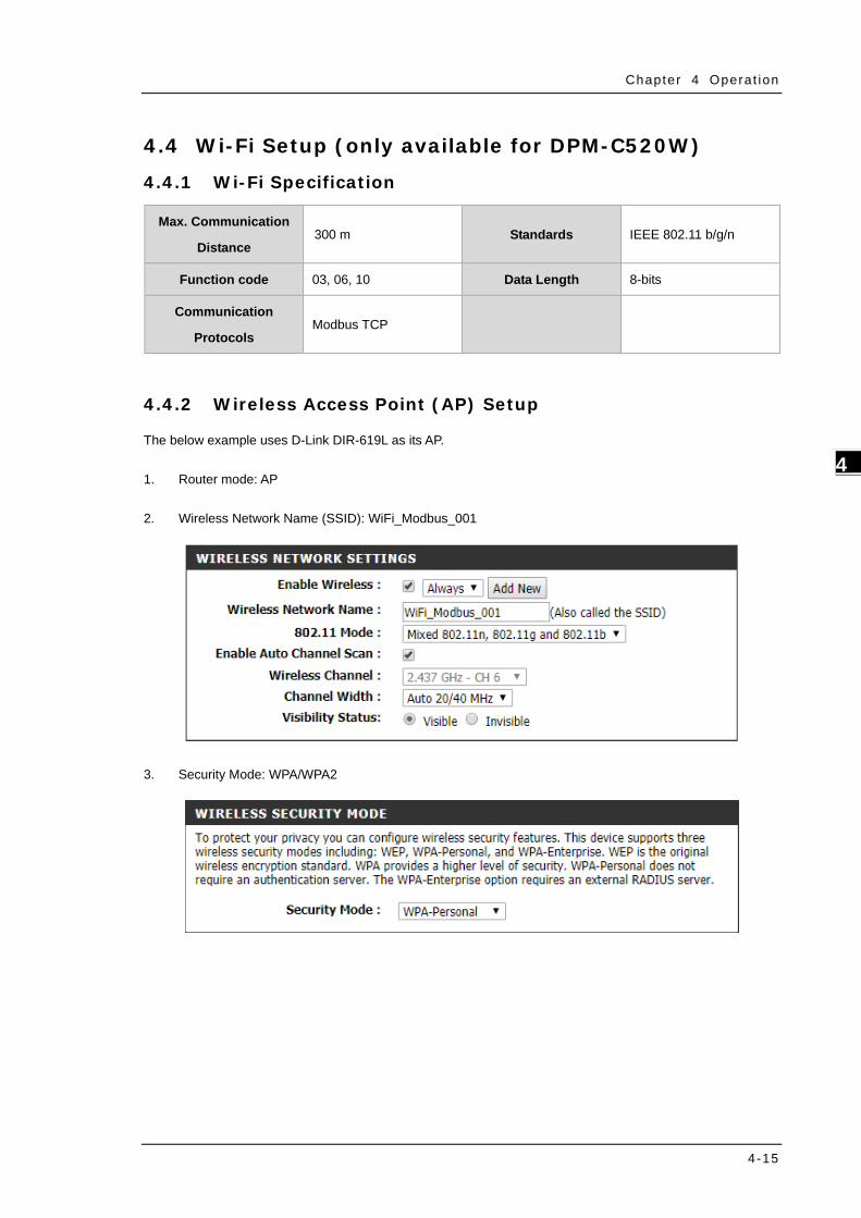
4.4.2 Wireless Access Point (AP) Setup
The below example uses D-Link DIR-619L as its AP.
1. Router mode: AP
2. Wireless Network Name (SSID): WiFi_Modbus_001
3. Security Mode: WPA/WPA2

DPM-C520/C520W/C320 Operat ion Manual
4-16
_4
4. Password of AP password (for WPA2) = "1234567890"
5. IP address of AP: 192.168.1.XXX
(Be sure the IP address stays in the same network, 192.168.1.XXX; after reset, some AP changes its IP
address section to 192.168.0.XXX.) In this example, we use 192.168.1.11 as the IP address of the router.
Chapter 4 Operat ion
4-17
4_
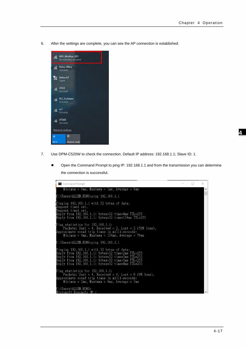
6. After the settings are complete, you can see the AP connection is established.
7. Use DPM-C520W to check the connection. Default IP address: 192.168.1.1; Slave ID: 1.
Open the Command Prompt to ping IP: 192.168.1.1 and from the transmission you can determine
the connection is successful.
DPM-C520/C520W/C320 Operat ion Manual
4-18
_4
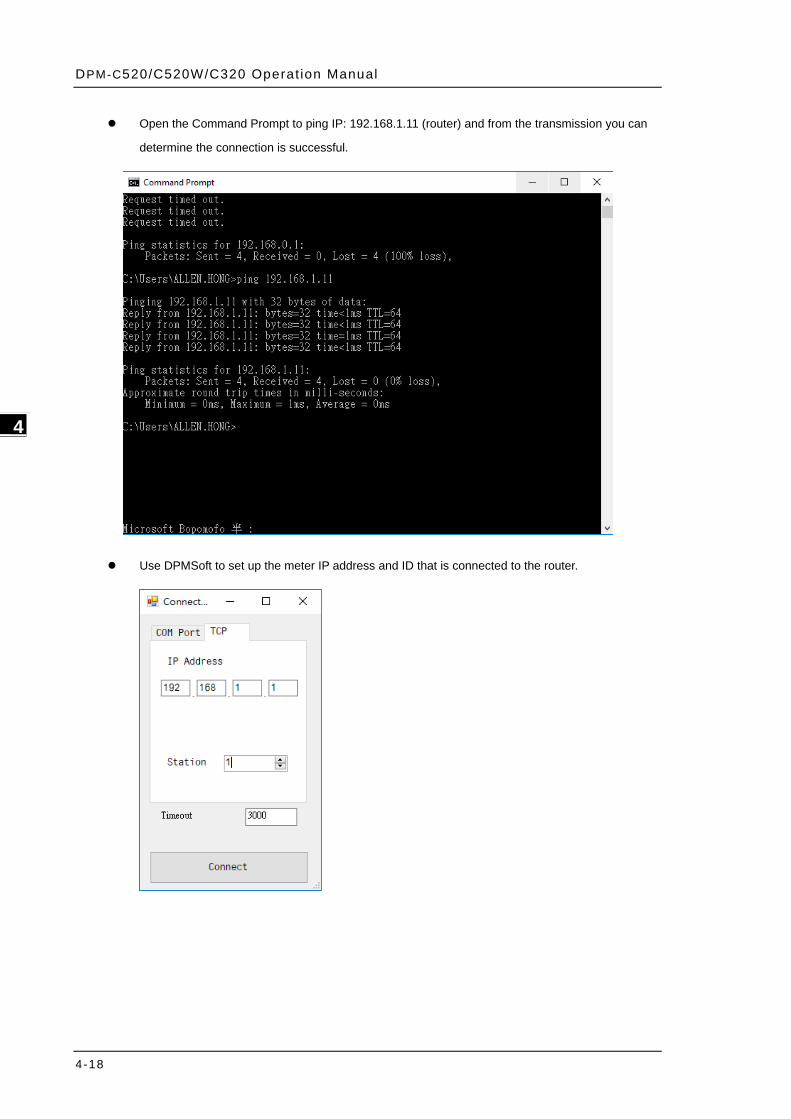
Open the Command Prompt to ping IP: 192.168.1.11 (router) and from the transmission you can
determine the connection is successful.
Use DPMSoft to set up the meter IP address and ID that is connected to the router.
Chapter 4 Operat ion
4-19
4_
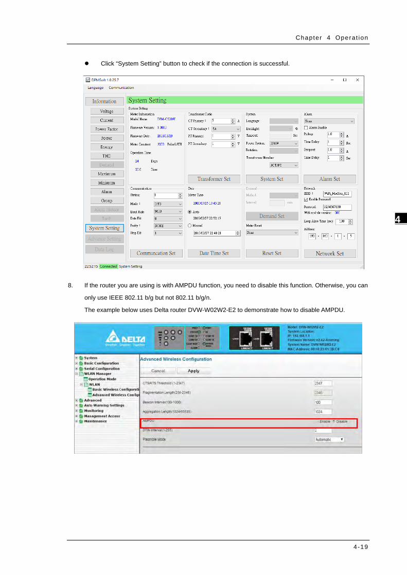
Click “System Setting” button to check if the connection is successful.
8. If the router you are using is with AMPDU function, you need to disable this function. Otherwise, you can
only use IEEE 802.11 b/g but not 802.11 b/g/n.
The example below uses Delta router DVW-W02W2-E2 to demonstrate how to disable AMPDU.
DPM-C520/C520W/C320 Operat ion Manual
4-20
_4
4.4.3 Advanced Wi-Fi Setup
Use DPMSoft to set up the router that DPM-C520W is going to connect, for example router’s SSID and
password. And after that you can use the specific information to search for the router that DPM-C520W can
connect to.
Setting points:
1. Use Ethernet cable to connect to your PC and router to avoid unreliable connection and packet lost during
transmission.
2. In DPMSoft, the settings for data transmission are shown below.
Transmission Time: 2 seconds per data
Timeout: 3 seconds
Failure: after 3 attempts
If data transmission fails, you need to search and try connecting to DPM-C502W again.
If you are using other meter-monitoring software, it is suggested to set the same settings for data
transmission.
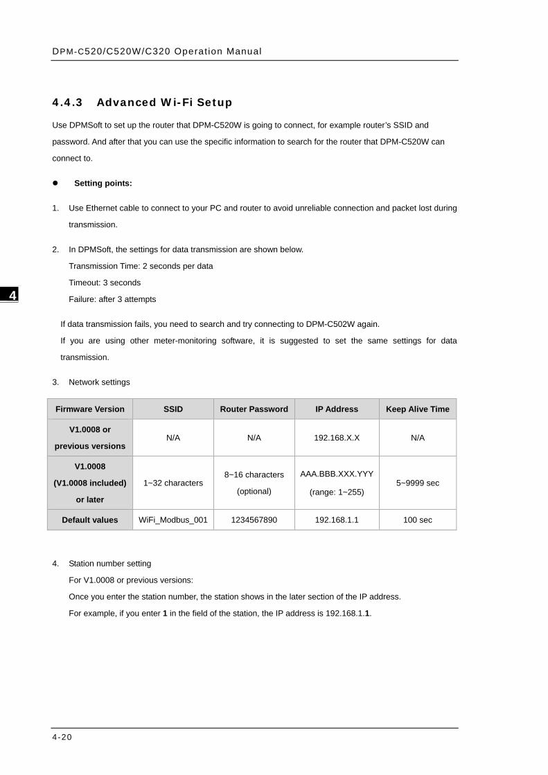
3. Network settings
Firmware Version SSID Router Password IP Address Keep Alive Time
V1.0008 or
previous versions N/A N/A 192.168.X.X N/A
V1.0008
(V1.0008 included)
or later
1~32 characters 8~16 characters
(optional)
AAA.BBB.XXX.YYY
(range: 1~255) 5~9999 sec
Default values WiFi_Modbus_001 1234567890 192.168.1.1 100 sec
4. Station number setting
For V1.0008 or previous versions:
Once you enter the station number, the station shows in the later section of the IP address.
For example, if you enter 1 in the field of the station, the IP address is 192.168.1.1.

Chapter 4 Operat ion
4-21
4_
For V1.0008 (V1.0008 included) or later:
Once you enter the station number, the station does NOT reflect on the IP address.
For example, if you enter 1 in the field of the station, the IP address is 192.158.1.5.
DPM-C520/C520W/C320 Operat ion Manual
4-22
_4
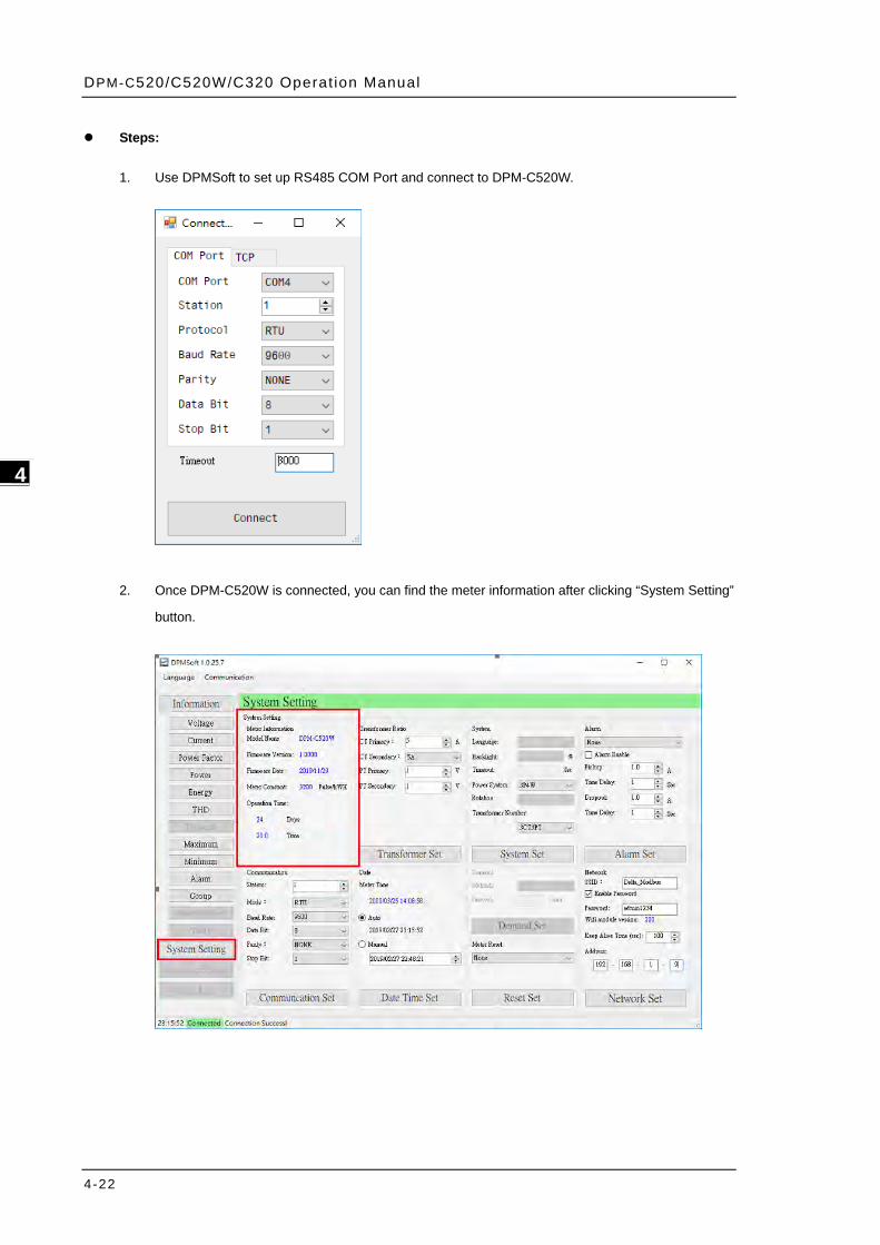
Steps:
1. Use DPMSoft to set up RS485 COM Port and connect to DPM-C520W.
2. Once DPM-C520W is connected, you can find the meter information after clicking “System Setting”
button.
Chapter 4 Operat ion
4-23
4_
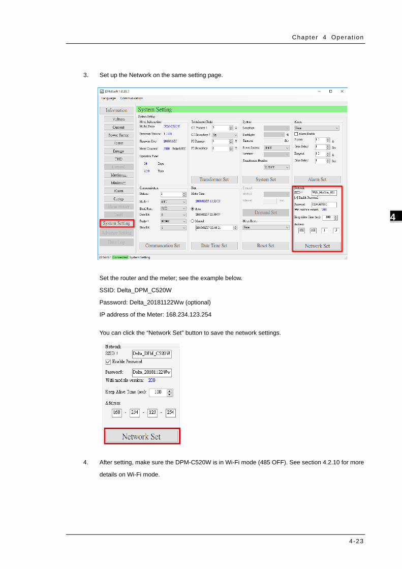
3. Set up the Network on the same setting page.
Set the router and the meter; see the example below.
SSID: Delta_DPM_C520W
Password: Delta_20181122Ww (optional)
IP address of the Meter: 168.234.123.254
You can click the “Network Set” button to save the network settings.
4. After setting, make sure the DPM-C520W is in Wi-Fi mode (485 OFF). See section 4.2.10 for more
details on Wi-Fi mode.
DPM-C520/C520W/C320 Operat ion Manual
4-24
_4
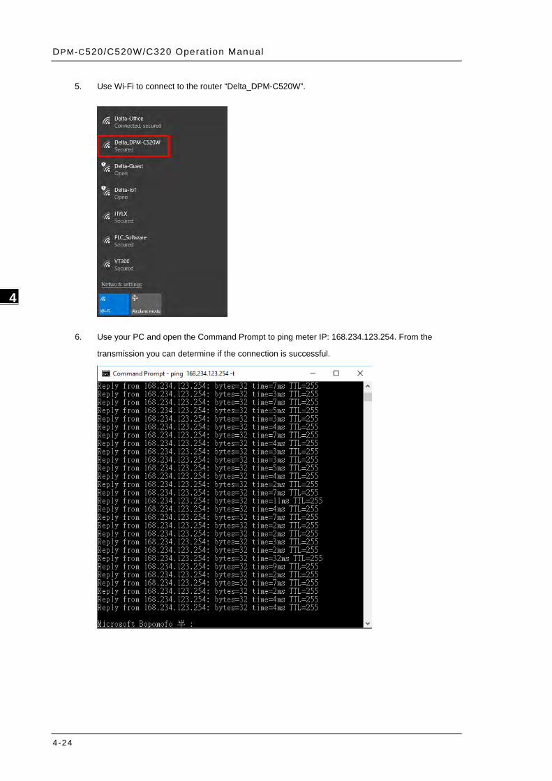
5. Use Wi-Fi to connect to the router “Delta_DPM-C520W”.
6. Use your PC and open the Command Prompt to ping meter IP: 168.234.123.254. From the
transmission you can determine if the connection is successful.
Chapter 4 Operat ion
4-25
4_
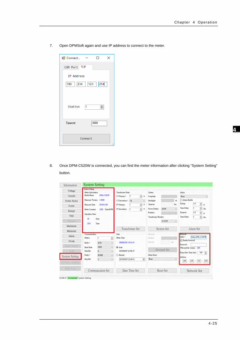
7. Open DPMSoft again and use IP address to connect to the meter.
8. Once DPM-C520W is connected, you can find the meter information after clicking “System Setting”
button.
DPM-C520/C520W/C320 Operat ion Manual
4-26
_4
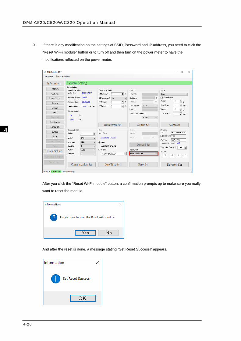
9. If there is any modification on the settings of SSID, Password and IP address, you need to click the
“Reset Wi-Fi module” button or to turn off and then turn on the power meter to have the
modifications reflected on the power meter.
After you click the “Reset Wi-Fi module” button, a confirmation prompts up to make sure you really
want to reset the module.
And after the reset is done, a message stating “Set Reset Success!” appears.
Chapter 4 Operat ion
4-27
4_
4.5 Power Analysis Values
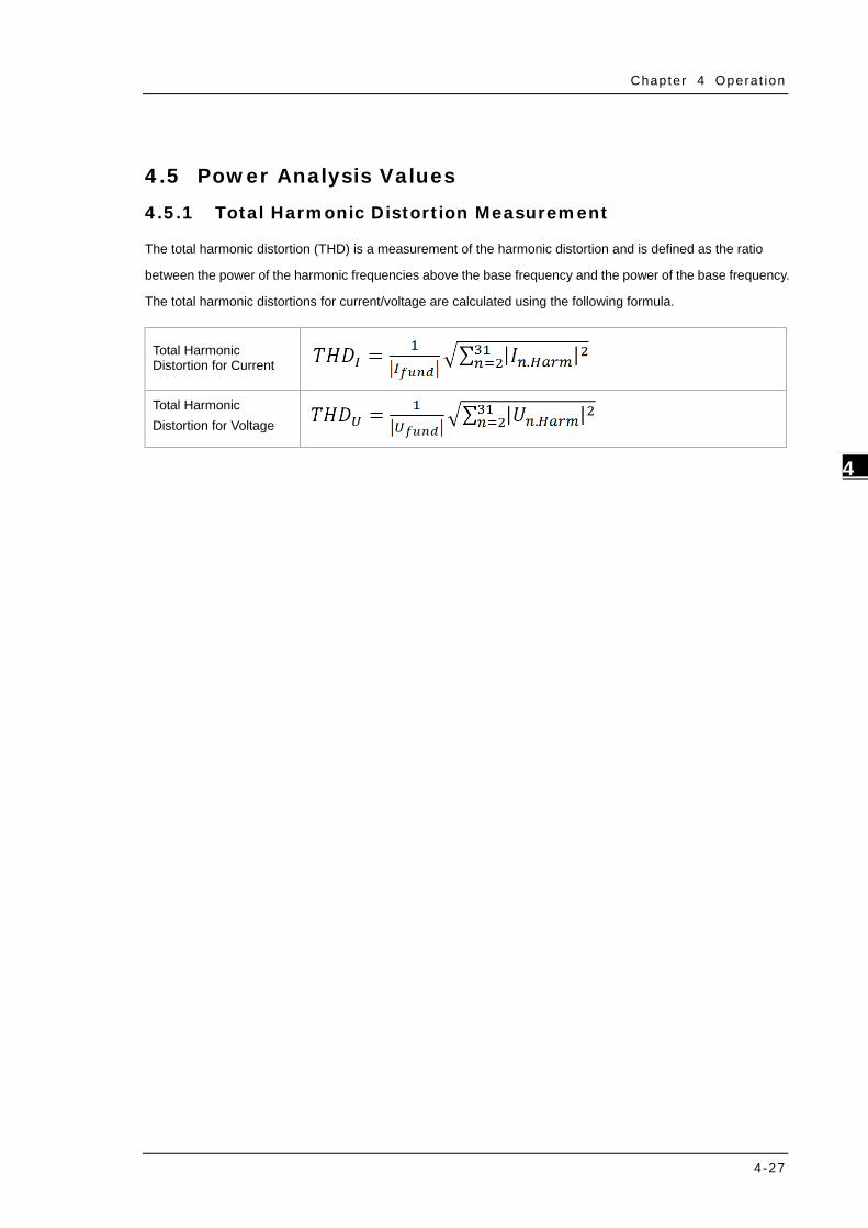
4.5.1 Total Harmonic Distortion Measurement
The total harmonic distortion (THD) is a measurement of the harmonic distortion and is defined as the ratio
between the power of the harmonic frequencies above the base frequency and the power of the base frequency.
The total harmonic distortions for current/voltage are calculated using the following formula.
Total Harmonic Distortion for Current
Total Harmonic Distortion for Voltage

DPM-C520/C520W/C320 Operat ion Manual
4-28
_4
MEMO
5-1
5 Chapter 5 Parameters and
Functions
Table of Contents 5.1 Overview of Parameters ..................................................................... 5-2
DPM-C520/C520W/C320 Operat ion Manual
5-2
_5
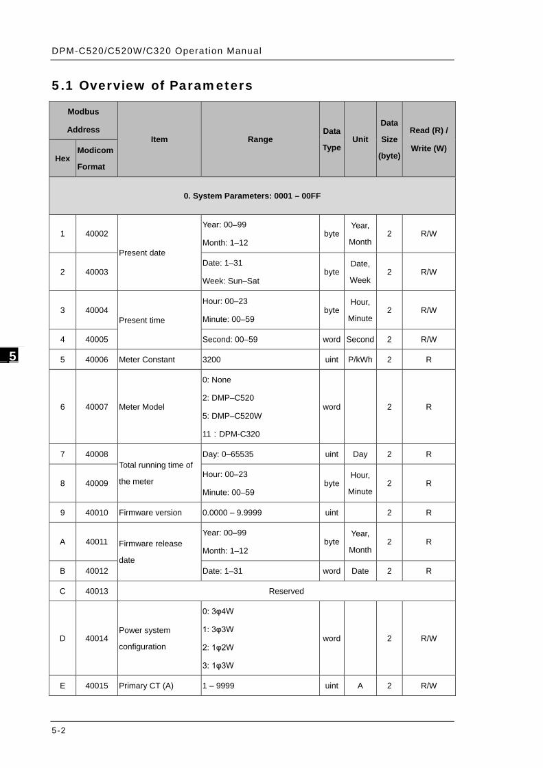
5.1 Overview of Parameters
Modbus
Address Item Range
Data
Type Unit
Data
Size
(byte)
Read (R) /
Write (W) Hex
Modicom
Format
0. System Parameters: 0001 – 00FF
1 40002
Present date
Year: 00–99
Month: 1–12 byte
Year,
Month 2 R/W
2 40003 Date: 1–31
Week: Sun–Sat byte
Date,
Week 2 R/W
3 40004 Present time
Hour: 00–23
Minute: 00–59 byte
Hour,
Minute 2 R/W
4 40005 Second: 00–59 word Second 2 R/W
5 40006 Meter Constant 3200 uint P/kWh 2 R
6 40007 Meter Model
0: None
2: DMP–C520
5: DMP–C520W
11:DPM-C320
word
2 R
7 40008 Total running time of
the meter
Day: 0–65535 uint Day 2 R
8 40009 Hour: 00–23
Minute: 00–59 byte
Hour,
Minute 2 R
9 40010 Firmware version 0.0000 – 9.9999 uint
2 R
A 40011 Firmware release
date
Year: 00–99
Month: 1–12 byte
Year,
Month 2 R
B 40012 Date: 1–31 word Date 2 R
C 40013 Reserved
D 40014 Power system
configuration
0: 3φ4W
1: 3φ3W
2: 1φ2W
3: 1φ3W
word
2 R/W
E 40015 Primary CT (A) 1 – 9999 uint A 2 R/W

Chapter 5 Parameters and Funct ions
5-3
_5
F 40016 Secondary CT (A) 0: 1A
1: 5A word A 2 R/W
10 40017 Primary PT 1 – 9999 uint V 2 R/W
11 40018 Secondary PT 1 – 9999 uint V 2 R/W
12 40019 Transformer
quantities
0: 3CT3PT
1: 3CT2PT
2: 3CT0PT
3: 2CT3PT
4: 2CT2PT
5: 2CT0PT
6: 1CT3PT
7: 1CT2PT
8: 1CT0PT
word
2 R/W
13 40020 Reserved
14 40021 Timeout 1 – 99 word Second 2 R/W
15 40022 Reserved
16 40023 Baud Rate
0: 9600
1: 19200
2: 38400
word bps 2 R/W
17 40024 Communication mode
0: WiFi Mode
(available for DPM-C520W)
1: 485 Mode
word
2 R/W
18 40025 Data bit 0: 8 word bit 2 R/W
19 40026 Stop bit
0: None
1: Even
2: Odd
word
2 R/W
1A 40027 Stop bit 0: 1 word bit 2 R/W
1B 40028 Modbus address 0 – 254 word
2 R/W
1C 40029 Reset
0: None
word
2 W 1: Reset to factory default
2: Reset energy value
3: Reset alarm
DPM-C520/C520W/C320 Operat ion Manual
5-4
_5
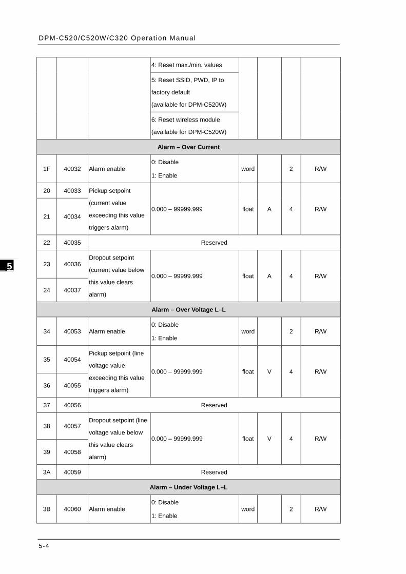
4: Reset max./min. values
5: Reset SSID, PWD, IP to
factory default
(available for DPM-C520W)
6: Reset wireless module
(available for DPM-C520W)
Alarm – Over Current
1F 40032 Alarm enable 0: Disable
1: Enable word
2 R/W
20 40033 Pickup setpoint
(current value
exceeding this value
triggers alarm)
0.000 – 99999.999 float A 4 R/W 21 40034
22 40035 Reserved
23 40036 Dropout setpoint
(current value below
this value clears
alarm)
0.000 – 99999.999 float A 4 R/W
24 40037
Alarm – Over Voltage L–L
34 40053 Alarm enable 0: Disable
1: Enable word
2 R/W
35 40054 Pickup setpoint (line
voltage value
exceeding this value
triggers alarm)
0.000 – 99999.999 float V 4 R/W
36 40055
37 40056 Reserved
38 40057 Dropout setpoint (line
voltage value below
this value clears
alarm)
0.000 – 99999.999 float V 4 R/W
39 40058
3A 40059 Reserved
Alarm – Under Voltage L–L
3B 40060 Alarm enable 0: Disable
1: Enable word
2 R/W
Chapter 5 Parameters and Funct ions
5-5
_5
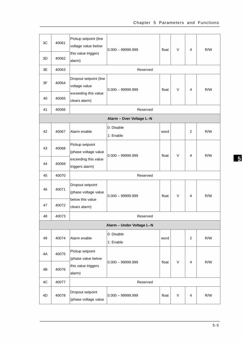
3C 40061 Pickup setpoint (line
voltage value below
this value triggers
alarm)
0.000 – 99999.999 float V 4 R/W
3D 40062
3E 40063 Reserved
3F 40064 Dropout setpoint (line
voltage value
exceeding this value
clears alarm)
0.000 – 99999.999 float V 4 R/W
40 40065
41 40066 Reserved
Alarm – Over Voltage L–N
42 40067 Alarm enable 0: Disable
1: Enable word
2 R/W
43 40068 Pickup setpoint
(phase voltage value
exceeding this value
triggers alarm)
0.000 – 99999.999 float V 4 R/W
44 40069
45 40070 Reserved
46 40071 Dropout setpoint
(phase voltage value
below this value
clears alarm)
0.000 – 99999.999 float V 4 R/W
47 40072
48 40073 Reserved
Alarm – Under Voltage L–N
49 40074 Alarm enable 0: Disable
1: Enable word
2 R/W
4A 40075 Pickup setpoint
(phase value below
this value triggers
alarm)
0.000 – 99999.999 float V 4 R/W
4B 40076
4C 40077 Reserved
4D 40078 Dropout setpoint
(phase voltage value 0.000 – 99999.999 float V 4 R/W
DPM-C520/C520W/C320 Operat ion Manual
5-6
_5
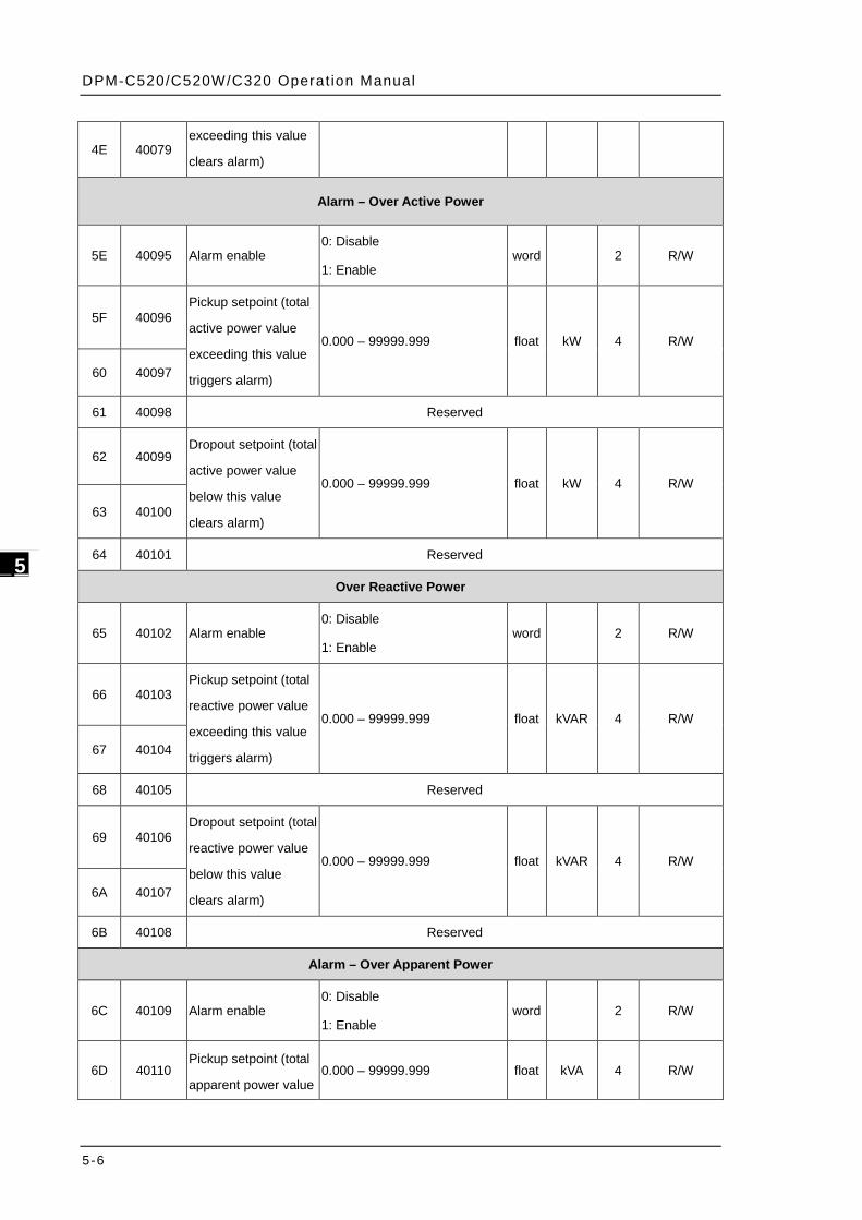
4E 40079 exceeding this value
clears alarm)
Alarm – Over Active Power
5E 40095 Alarm enable 0: Disable
1: Enable word
2 R/W
5F 40096 Pickup setpoint (total
active power value
exceeding this value
triggers alarm)
0.000 – 99999.999 float kW 4 R/W
60 40097
61 40098 Reserved
62 40099 Dropout setpoint (total
active power value
below this value
clears alarm)
0.000 – 99999.999 float kW 4 R/W
63 40100
64 40101 Reserved
Over Reactive Power
65 40102 Alarm enable 0: Disable
1: Enable word
2 R/W
66 40103 Pickup setpoint (total
reactive power value
exceeding this value
triggers alarm)
0.000 – 99999.999 float kVAR 4 R/W
67 40104
68 40105 Reserved
69 40106 Dropout setpoint (total
reactive power value
below this value
clears alarm)
0.000 – 99999.999 float kVAR 4 R/W
6A 40107
6B 40108 Reserved
Alarm – Over Apparent Power
6C 40109 Alarm enable 0: Disable
1: Enable word
2 R/W
6D 40110 Pickup setpoint (total
apparent power value 0.000 – 99999.999 float kVA 4 R/W
Chapter 5 Parameters and Funct ions
5-7
_5
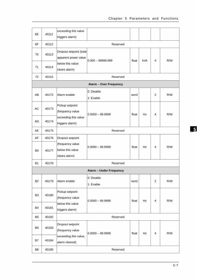
6E 40111 exceeding this value
triggers alarm)
6F 40112 Reserved
70 40113 Dropout setpoint (total
apparent power value
below this value
clears alarm)
0.000 – 99999.999 float kVA 4 R/W
71 40114
72 40115 Reserved
Alarm – Over Frequency
AB 40172 Alarm enable 0: Disable
1: Enable word
2 R/W
AC 40173 Pickup setpoint
(frequency value
exceeding this value
triggers alarm)
0.0000 – 99.9999 float Hz 4 R/W
AD 40174
AE 40175 Reserved
AF 40176 Dropout setpoint
(frequency value
below this value
clears alarm)
0.0000 – 99.9999 float Hz 4
R/W
B0 40177
B1 40178 Reserved
Alarm – Under Frequency
B2 40179 Alarm enable 0: Disable
1: Enable word
2 R/W
B3 40180 Pickup setpoint
(frequency value
below this value
triggers alarm)
0.0000 – 99.9999 float Hz 4 R/W
B4 40181
B5 40182 Reserved
B6 40183 Dropout setpoint
(frequency value
exceeding this value,
alarm cleared)
0.0000 – 99.9999 float Hz 4 R/W
B7 40184
B8 40185 Reserved
DPM-C520/C520W/C320 Operat ion Manual
5-8
_5
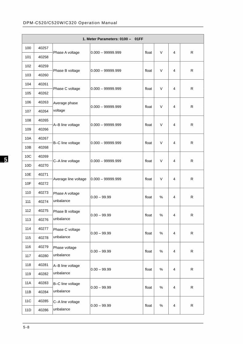
1. Meter Parameters: 0100 – 01FF
100 40257 Phase A voltage 0.000 – 99999.999 float V 4 R
101 40258
102 40259 Phase B voltage 0.000 – 99999.999 float V 4 R
103 40260
104 40261 Phase C voltage 0.000 – 99999.999 float V 4 R
105 40262
106 40263 Average phase
voltage 0.000 – 99999.999 float V 4 R
107 40264
108 40265 A–B line voltage 0.000 – 99999.999 float V 4 R
109 40266
10A 40267 B–C line voltage 0.000 – 99999.999 float V 4 R
10B 40268
10C 40269 C–A line voltage 0.000 – 99999.999 float V 4 R
10D 40270
10E 40271 Average line voltage 0.000 – 99999.999 float V 4 R
10F 40272
110 40273 Phase A voltage
unbalance 0.00 – 99.99 float % 4 R
111 40274
112 40275 Phase B voltage
unbalance 0.00 – 99.99 float % 4 R
113 40276
114 40277 Phase C voltage
unbalance 0.00 – 99.99 float % 4 R
115 40278
116 40279 Phase voltage
unbalance 0.00 – 99.99 float % 4 R
117 40280
118 40281 A–B line voltage
unbalance 0.00 – 99.99 float % 4 R
119 40282
11A 40283 B–C line voltage
unbalance 0.00 – 99.99 float % 4 R
11B 40284
11C 40285 C–A line voltage
unbalance 0.00 – 99.99 float % 4 R
11D 40286
Chapter 5 Parameters and Funct ions
5-9
_5
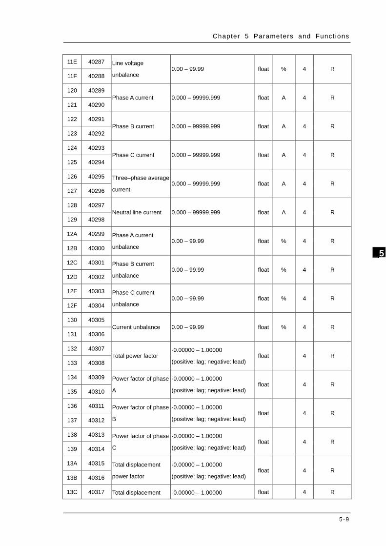
11E 40287 Line voltage
unbalance 0.00 – 99.99 float % 4 R
11F 40288
120 40289 Phase A current 0.000 – 99999.999 float A 4 R
121 40290
122 40291 Phase B current 0.000 – 99999.999 float A 4 R
123 40292
124 40293 Phase C current 0.000 – 99999.999 float A 4 R
125 40294
126 40295 Three–phase average
current 0.000 – 99999.999 float A 4 R
127 40296
128 40297 Neutral line current 0.000 – 99999.999 float A 4 R
129 40298
12A 40299 Phase A current
unbalance 0.00 – 99.99 float % 4 R
12B 40300
12C 40301 Phase B current
unbalance 0.00 – 99.99 float % 4 R
12D 40302
12E 40303 Phase C current
unbalance 0.00 – 99.99 float % 4 R
12F 40304
130 40305 Current unbalance 0.00 – 99.99 float % 4 R
131 40306
132 40307 Total power factor
-0.00000 – 1.00000
(positive: lag; negative: lead) float
4 R
133 40308
134 40309 Power factor of phase
A
-0.00000 – 1.00000
(positive: lag; negative: lead) float
4 R
135 40310
136 40311 Power factor of phase
B
-0.00000 – 1.00000
(positive: lag; negative: lead) float
4 R
137 40312
138 40313 Power factor of phase
C
-0.00000 – 1.00000
(positive: lag; negative: lead) float
4 R
139 40314
13A 40315 Total displacement
power factor
-0.00000 – 1.00000
(positive: lag; negative: lead) float
4 R
13B 40316
13C 40317 Total displacement -0.00000 – 1.00000 float
4 R

DPM-C520/C520W/C320 Operat ion Manual
5-10
_5
13D 40318 power factor of phase
A
(positive: lag; negative: lead)
13E 40319 Total displacement
power factor of phase
B
-0.00000 – 1.00000
(positive: lag; negative: lead) float
4 R
13F 40320
140 40321 Total displacement
power factor of phase
C
-0.00000 – 1.00000
(positive: lag; negative: lead) float
4 R
141 40322
142 40323 Frequency 0.0000 – 99.9999 float Hz 4 R
143 40324
144 40325 Total instantaneous
active power 0.000 – 99999.999 float kW 4 R
145 40326
146 40327 Instantaneous active
power of phase A 0.000 – 99999.999 float kW 4 R
147 40328
148 40329 Instantaneous active
power of phase B 0.000 – 99999.999 float kW 4 R
149 40330
14A 40331 Instantaneous active
power of phase C 0.000 – 99999.999 float kW 4 R
14B 40332
14C 40333 Total instantaneous
reactive power 0.000 – 99999.999 float kVAR 4 R
14D 40334
14E 40335 Instantaneous
reactive power of
phase A
0.000 – 99999.999 float kVAR 4 R 14F 40336
150 40337 Instantaneous
reactive power of
phase B
0.000 – 99999.999 float kVAR 4 R 151 40338
152 40339 Instantaneous
reactive power of
phase C
0.000 – 99999.999 float kVAR 4 R 153 40340
154 40341 Instantaneous
apparent power 0.000 – 99999.999 float kVA 4 R
155 40342
156 40343 Instantaneous 0.000 – 99999.999 float kVA 4 R
Chapter 5 Parameters and Funct ions
5-11
_5
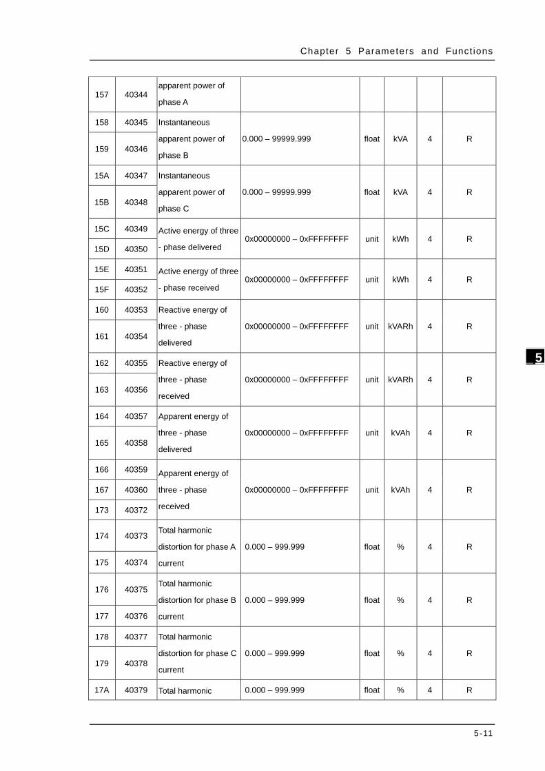
157 40344 apparent power of
phase A
158 40345 Instantaneous
apparent power of
phase B
0.000 – 99999.999 float kVA 4 R 159 40346
15A 40347 Instantaneous
apparent power of
phase C
0.000 – 99999.999 float kVA 4 R 15B 40348
15C 40349 Active energy of three
- phase delivered 0x00000000 – 0xFFFFFFFF unit kWh 4 R
15D 40350
15E 40351 Active energy of three
- phase received 0x00000000 – 0xFFFFFFFF unit kWh 4 R
15F 40352
160 40353 Reactive energy of
three - phase
delivered
0x00000000 – 0xFFFFFFFF unit kVARh 4 R 161 40354
162 40355 Reactive energy of
three - phase
received
0x00000000 – 0xFFFFFFFF unit kVARh 4 R 163 40356
164 40357 Apparent energy of
three - phase
delivered
0x00000000 – 0xFFFFFFFF unit kVAh 4 R 165 40358
166 40359 Apparent energy of
three - phase
received
0x00000000 – 0xFFFFFFFF unit kVAh 4 R 167 40360
173 40372
174 40373 Total harmonic
distortion for phase A
current
0.000 – 999.999 float % 4 R
175 40374
176 40375 Total harmonic
distortion for phase B
current
0.000 – 999.999 float % 4 R
177 40376
178 40377 Total harmonic
distortion for phase C
current
0.000 – 999.999 float % 4 R 179 40378
17A 40379 Total harmonic 0.000 – 999.999 float % 4 R
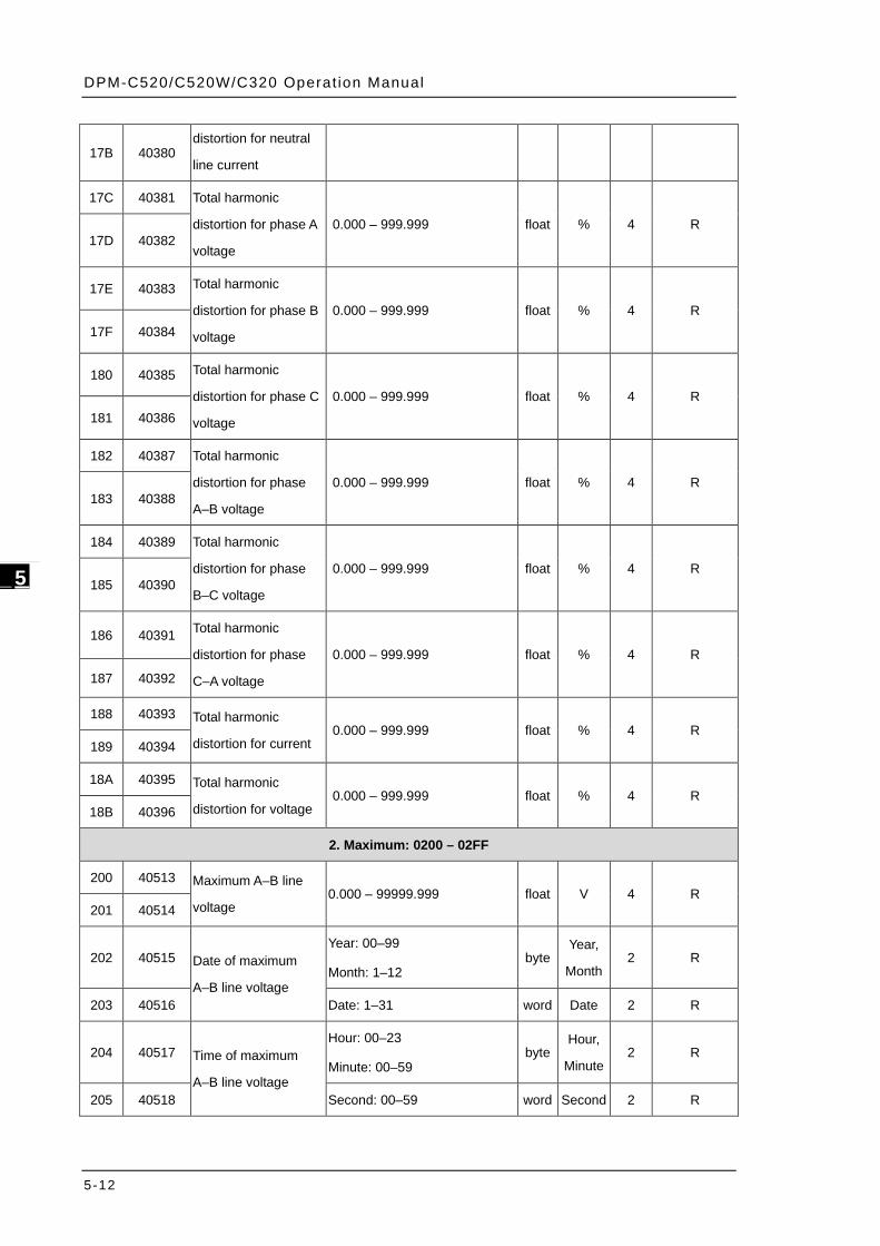
DPM-C520/C520W/C320 Operat ion Manual
5-12
_5
17B 40380 distortion for neutral
line current
17C 40381 Total harmonic
distortion for phase A
voltage
0.000 – 999.999 float % 4 R 17D 40382
17E 40383 Total harmonic
distortion for phase B
voltage
0.000 – 999.999 float % 4 R 17F 40384
180 40385 Total harmonic
distortion for phase C
voltage
0.000 – 999.999 float % 4 R 181 40386
182 40387 Total harmonic
distortion for phase
A–B voltage
0.000 – 999.999 float % 4 R 183 40388
184 40389 Total harmonic
distortion for phase
B–C voltage
0.000 – 999.999 float % 4 R 185 40390
186 40391 Total harmonic
distortion for phase
C–A voltage
0.000 – 999.999 float % 4 R
187 40392
188 40393 Total harmonic
distortion for current 0.000 – 999.999 float % 4 R
189 40394
18A 40395 Total harmonic
distortion for voltage 0.000 – 999.999 float % 4 R
18B 40396
2. Maximum: 0200 – 02FF
200 40513 Maximum A–B line
voltage 0.000 – 99999.999 float V 4 R
201 40514
202 40515 Date of maximum
A–B line voltage
Year: 00–99
Month: 1–12 byte
Year,
Month 2 R
203 40516 Date: 1–31 word Date 2 R
204 40517 Time of maximum
A–B line voltage
Hour: 00–23
Minute: 00–59 byte
Hour,
Minute 2 R
205 40518 Second: 00–59 word Second 2 R
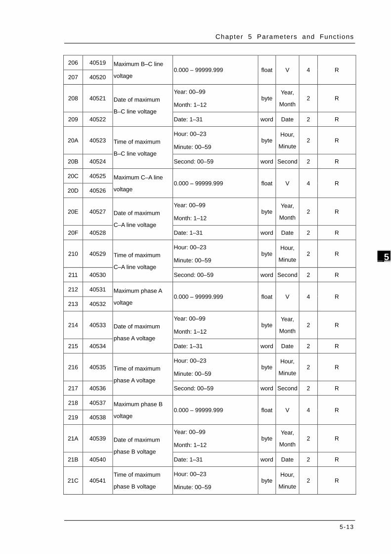
Chapter 5 Parameters and Funct ions
5-13
_5
206 40519 Maximum B–C line
voltage 0.000 – 99999.999 float V 4 R
207 40520
208 40521 Date of maximum
B–C line voltage
Year: 00–99
Month: 1–12 byte
Year,
Month 2 R
209 40522 Date: 1–31 word Date 2 R
20A 40523 Time of maximum
B–C line voltage
Hour: 00–23
Minute: 00–59 byte
Hour,
Minute 2 R
20B 40524 Second: 00–59 word Second 2 R
20C 40525 Maximum C–A line
voltage 0.000 – 99999.999 float V 4 R
20D 40526
20E 40527 Date of maximum
C–A line voltage
Year: 00–99
Month: 1–12 byte
Year,
Month 2 R
20F 40528 Date: 1–31 word Date 2 R
210 40529 Time of maximum
C–A line voltage
Hour: 00–23
Minute: 00–59 byte
Hour,
Minute 2 R
211 40530 Second: 00–59 word Second 2 R
212 40531 Maximum phase A
voltage 0.000 – 99999.999 float V 4 R
213 40532
214 40533 Date of maximum
phase A voltage
Year: 00–99
Month: 1–12 byte
Year,
Month 2 R
215 40534 Date: 1–31 word Date 2 R
216 40535 Time of maximum
phase A voltage
Hour: 00–23
Minute: 00–59 byte
Hour,
Minute 2 R
217 40536 Second: 00–59 word Second 2 R
218 40537 Maximum phase B
voltage 0.000 – 99999.999 float V 4 R
219 40538
21A 40539 Date of maximum
phase B voltage
Year: 00–99
Month: 1–12 byte
Year,
Month 2 R
21B 40540 Date: 1–31 word Date 2 R
21C 40541 Time of maximum
phase B voltage
Hour: 00–23
Minute: 00–59 byte
Hour,
Minute 2 R
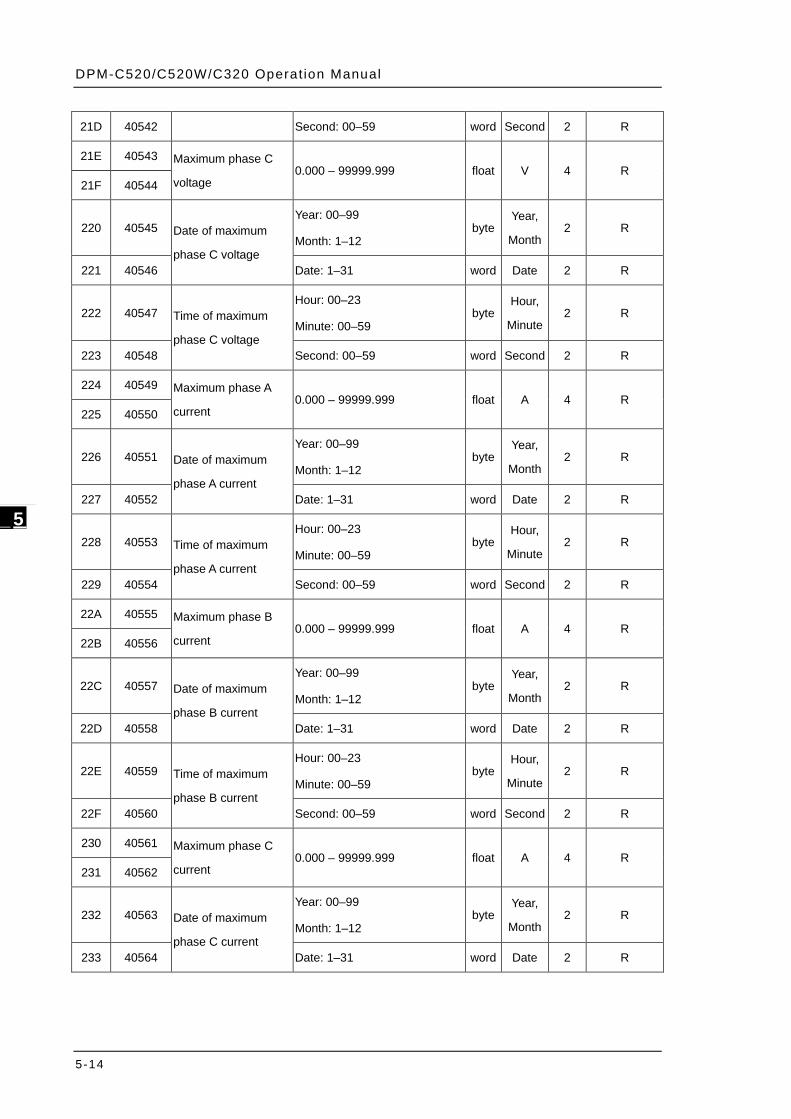
DPM-C520/C520W/C320 Operat ion Manual
5-14
_5
21D 40542 Second: 00–59 word Second 2 R
21E 40543 Maximum phase C
voltage 0.000 – 99999.999 float V 4 R
21F 40544
220 40545 Date of maximum
phase C voltage
Year: 00–99
Month: 1–12 byte
Year,
Month 2 R
221 40546 Date: 1–31 word Date 2 R
222 40547 Time of maximum
phase C voltage
Hour: 00–23
Minute: 00–59 byte
Hour,
Minute 2 R
223 40548 Second: 00–59 word Second 2 R
224 40549 Maximum phase A
current 0.000 – 99999.999 float A 4 R
225 40550
226 40551 Date of maximum
phase A current
Year: 00–99
Month: 1–12 byte
Year,
Month 2 R
227 40552 Date: 1–31 word Date 2 R
228 40553 Time of maximum
phase A current
Hour: 00–23
Minute: 00–59 byte
Hour,
Minute 2 R
229 40554 Second: 00–59 word Second 2 R
22A 40555 Maximum phase B
current 0.000 – 99999.999 float A 4 R
22B 40556
22C 40557 Date of maximum
phase B current
Year: 00–99
Month: 1–12 byte
Year,
Month 2 R
22D 40558 Date: 1–31 word Date 2 R
22E 40559 Time of maximum
phase B current
Hour: 00–23
Minute: 00–59 byte
Hour,
Minute 2 R
22F 40560 Second: 00–59 word Second 2 R
230 40561 Maximum phase C
current 0.000 – 99999.999 float A 4 R
231 40562
232 40563 Date of maximum
phase C current
Year: 00–99
Month: 1–12 byte
Year,
Month 2 R
233 40564 Date: 1–31 word Date 2 R
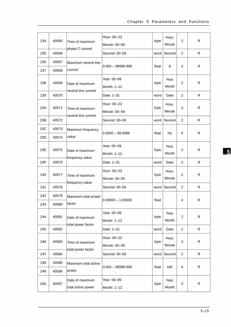
Chapter 5 Parameters and Funct ions
5-15
_5
234 40565 Time of maximum
phase C current
Hour: 00–23
Minute: 00–59 byte
Hour,
Minute 2 R
235 40566 Second: 00–59 word Second 2 R
236 40567 Maximum neutral line
current 0.000 – 99999.999 float A 4 R
237 40568
238 40569 Date of maximum
neutral line current
Year: 00–99
Month: 1–12 byte
Year,
Month 2 R
239 40570 Date: 1–31 word Date 2 R
23A 40571 Time of maximum
neutral line current
Hour: 00–23
Minute: 00–59 byte
Hour,
Minute 2 R
23B 40572 Second: 00–59 word Second 2 R
23C 40573 Maximum frequency
value 0.0000 – 99.9999 float Hz 4 R
23D 40574
23E 40575 Date of maximum
frequency value
Year: 00–99
Month: 1–12 byte
Year,
Month 2 R
23F 40576 Date: 1–31 word Date 2 R
240 40577 Time of maximum
frequency value
Hour: 00–23
Minute: 00–59 byte
Hour,
Minute 2 R
241 40578 Second: 00–59 word Second 2 R
242 40579 Maximum total power
factor 0.00000 – 1.00000 float
4 R
243 40580
244 40581 Date of maximum
total power factor
Year: 00–99
Month: 1–12 byte
Year,
Month 2 R
245 40582 Date: 1–31 word Date 2 R
246 40583 Time of maximum
total power factor
Hour: 00–23
Minute: 00–59 byte
Hour,
Minute 2 R
247 40584 Second: 00–59 word Second 2 R
248 40585 Maximum total active
power 0.000 – 99999.999 float kW 4 R
249 40586
24A 40587 Date of maximum
total active power
Year: 00–99
Month: 1–12 byte
Year,
Month 2 R
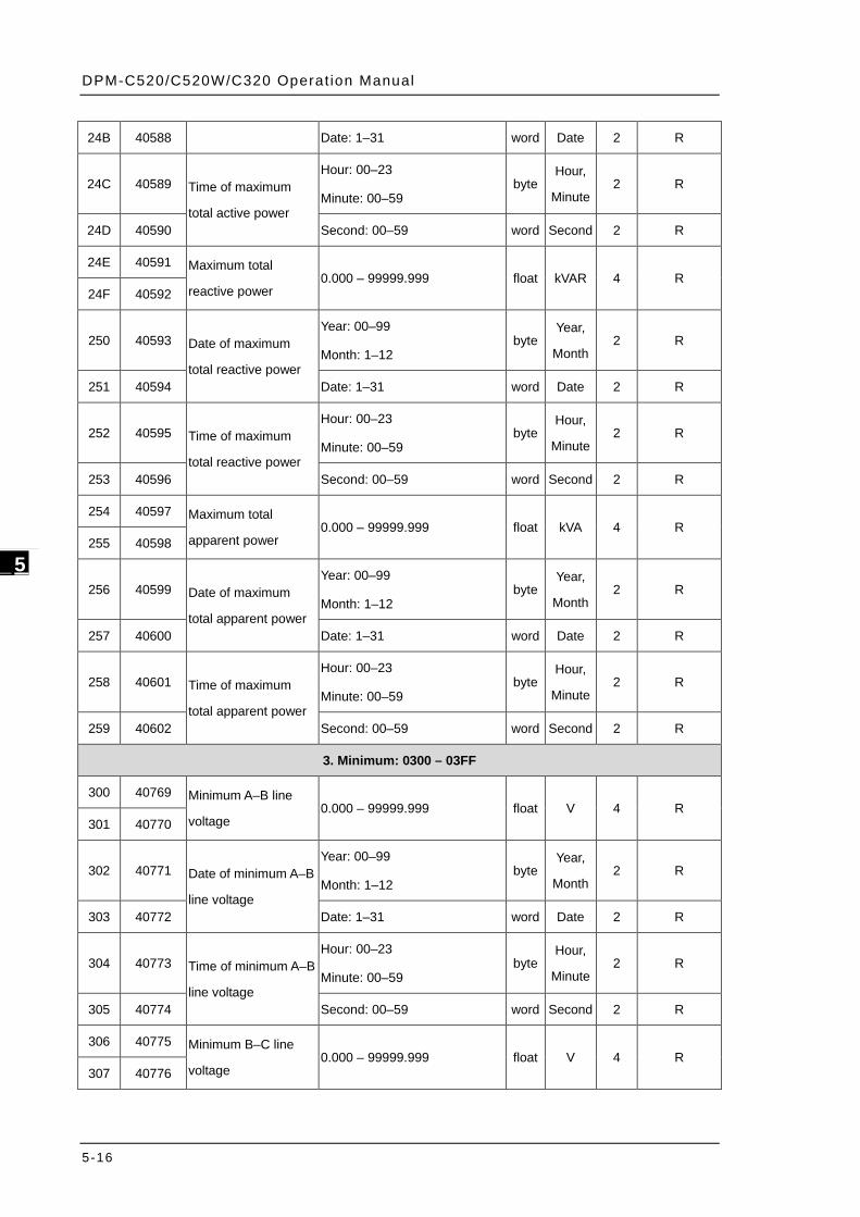
DPM-C520/C520W/C320 Operat ion Manual
5-16
_5
24B 40588 Date: 1–31 word Date 2 R
24C 40589 Time of maximum
total active power
Hour: 00–23
Minute: 00–59 byte
Hour,
Minute 2 R
24D 40590 Second: 00–59 word Second 2 R
24E 40591 Maximum total
reactive power 0.000 – 99999.999 float kVAR 4 R
24F 40592
250 40593 Date of maximum
total reactive power
Year: 00–99
Month: 1–12 byte
Year,
Month 2 R
251 40594 Date: 1–31 word Date 2 R
252 40595 Time of maximum
total reactive power
Hour: 00–23
Minute: 00–59 byte
Hour,
Minute 2 R
253 40596 Second: 00–59 word Second 2 R
254 40597 Maximum total
apparent power 0.000 – 99999.999 float kVA 4 R
255 40598
256 40599 Date of maximum
total apparent power
Year: 00–99
Month: 1–12 byte
Year,
Month 2 R
257 40600 Date: 1–31 word Date 2 R
258 40601 Time of maximum
total apparent power
Hour: 00–23
Minute: 00–59 byte
Hour,
Minute 2 R
259 40602 Second: 00–59 word Second 2 R
3. Minimum: 0300 – 03FF
300 40769 Minimum A–B line
voltage 0.000 – 99999.999 float V 4 R
301 40770
302 40771 Date of minimum A–B
line voltage
Year: 00–99
Month: 1–12 byte
Year,
Month 2 R
303 40772 Date: 1–31 word Date 2 R
304 40773 Time of minimum A–B
line voltage
Hour: 00–23
Minute: 00–59 byte
Hour,
Minute 2 R
305 40774 Second: 00–59 word Second 2 R
306 40775 Minimum B–C line
voltage 0.000 – 99999.999 float V 4 R
307 40776
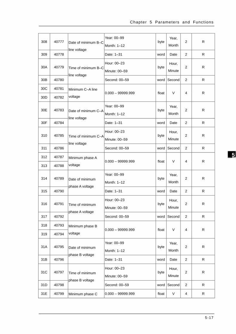
Chapter 5 Parameters and Funct ions
5-17
_5
308 40777 Date of minimum B–C
line voltage
Year: 00–99
Month: 1–12 byte
Year,
Month 2 R
309 40778 Date: 1–31 word Date 2 R
30A 40779 Time of minimum B–C
line voltage
Hour: 00–23
Minute: 00–59 byte
Hour,
Minute 2 R
30B 40780 Second: 00–59 word Second 2 R
30C 40781 Minimum C–A line
voltage 0.000 – 99999.999 float V 4 R
30D 40782
30E 40783 Date of minimum C–A
line voltage
Year: 00–99
Month: 1–12 byte
Year,
Month 2 R
30F 40784 Date: 1–31 word Date 2 R
310 40785 Time of minimum C–A
line voltage
Hour: 00–23
Minute: 00–59 byte
Hour,
Minute 2 R
311 40786 Second: 00–59 word Second 2 R
312 40787 Minimum phase A
voltage 0.000 – 99999.999 float V 4 R
313 40788
314 40789 Date of minimum
phase A voltage
Year: 00–99
Month: 1–12 byte
Year,
Month 2 R
315 40790 Date: 1–31 word Date 2 R
316 40791 Time of minimum
phase A voltage
Hour: 00–23
Minute: 00–59 byte
Hour,
Minute 2 R
317 40792 Second: 00–59 word Second 2 R
318 40793 Minimum phase B
voltage 0.000 – 99999.999 float V 4 R
319 40794
31A 40795 Date of minimum
phase B voltage
Year: 00–99
Month: 1–12 byte
Year,
Month 2 R
31B 40796 Date: 1–31 word Date 2 R
31C 40797 Time of minimum
phase B voltage
Hour: 00–23
Minute: 00–59 byte
Hour,
Minute 2 R
31D 40798 Second: 00–59 word Second 2 R
31E 40799 Minimum phase C 0.000 – 99999.999 float V 4 R

DPM-C520/C520W/C320 Operat ion Manual
5-18
_5
31F 40800 voltage
320 40801 Date of minimum
phase C voltage
Year: 00–99
Month: 1–12 byte
Year,
Month 2 R
321 40802 Date: 1–31 word Date 2 R
322 40803 Time of minimum
phase C voltage
Hour: 00–23
Minute: 00–59 byte
Hour,
Minute 2 R
323 40804 Second: 00–59 word Second 2 R
324 40805 Minimum phase A
current 0.000 – 99999.999 float A 4 R
325 40806
326 40807 Date of minimum
phase A current
Year: 00–99
Month: 1–12 byte
Year,
Month 2 R
327 40808 Date: 1–31 word Date 2 R
328 40809 Time of minimum
phase A current
Hour: 00–23
Minute: 00–59 byte
Hour,
Minute 2 R
329 40810 Second: 00–59 word Second 2 R
32A 40811 Minimum phase B
current 0.000 – 99999.999 float A 4 R
32B 40812
32C 40813 Date of minimum
phase B current
Year: 00–99
Month: 1–12 byte
Year,
Month 2 R
32D 40814 Date: 1–31 word Date 2 R
32E 40815 Time of minimum
phase B current
Hour: 00–23
Minute: 00–59 byte
Hour,
Minute 2 R
32F 40816 Second: 00–59 word Second 2 R
330 40817 Minimum phase C
current 0.000 – 99999.999 float A 4 R
331 40818
332 40819 Date of minimum
phase C current
Year: 00–99
Month: 1–12 byte
Year,
Month 2 R
333 40820 Date: 1–31 word Date 2 R
334 40821 Time of minimum
phase C current
Hour: 00–23
Minute: 00–59 byte
Hour,
Minute 2 R
335 40822 Second: 00–59 word Second 2 R
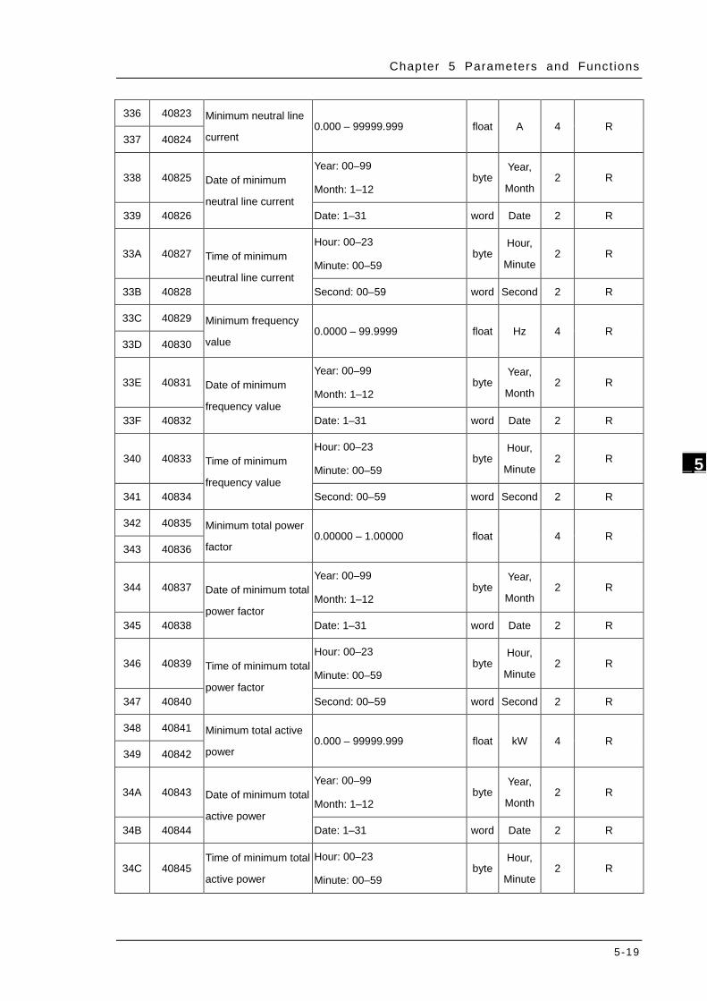
Chapter 5 Parameters and Funct ions
5-19
_5
336 40823 Minimum neutral line
current 0.000 – 99999.999 float A 4 R
337 40824
338 40825 Date of minimum
neutral line current
Year: 00–99
Month: 1–12 byte
Year,
Month 2 R
339 40826 Date: 1–31 word Date 2 R
33A 40827 Time of minimum
neutral line current
Hour: 00–23
Minute: 00–59 byte
Hour,
Minute 2 R
33B 40828 Second: 00–59 word Second 2 R
33C 40829 Minimum frequency
value 0.0000 – 99.9999 float Hz 4 R
33D 40830
33E 40831 Date of minimum
frequency value
Year: 00–99
Month: 1–12 byte
Year,
Month 2 R
33F 40832 Date: 1–31 word Date 2 R
340 40833 Time of minimum
frequency value
Hour: 00–23
Minute: 00–59 byte
Hour,
Minute 2 R
341 40834 Second: 00–59 word Second 2 R
342 40835 Minimum total power
factor 0.00000 – 1.00000 float
4 R
343 40836
344 40837 Date of minimum total
power factor
Year: 00–99
Month: 1–12 byte
Year,
Month 2 R
345 40838 Date: 1–31 word Date 2 R
346 40839 Time of minimum total
power factor
Hour: 00–23
Minute: 00–59 byte
Hour,
Minute 2 R
347 40840 Second: 00–59 word Second 2 R
348 40841 Minimum total active
power 0.000 – 99999.999 float kW 4 R
349 40842
34A 40843 Date of minimum total
active power
Year: 00–99
Month: 1–12 byte
Year,
Month 2 R
34B 40844 Date: 1–31 word Date 2 R
34C 40845 Time of minimum total
active power
Hour: 00–23
Minute: 00–59 byte
Hour,
Minute 2 R
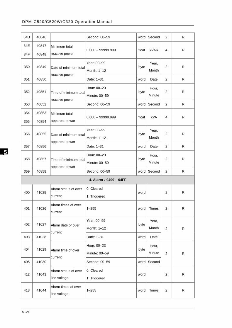
DPM-C520/C520W/C320 Operat ion Manual
5-20
_5
34D 40846 Second: 00–59 word Second 2 R
34E 40847 Minimum total
reactive power 0.000 – 99999.999 float kVAR 4 R
34F 40848
350 40849 Date of minimum total
reactive power
Year: 00–99
Month: 1–12 byte
Year,
Month 2 R
351 40850 Date: 1–31 word Date 2 R
352 40851 Time of minimum total
reactive power
Hour: 00–23
Minute: 00–59 byte
Hour,
Minute 2 R
353 40852 Second: 00–59 word Second 2 R
354 40853 Minimum total
apparent power 0.000 – 99999.999 float kVA 4 R
355 40854
356 40855 Date of minimum total
apparent power
Year: 00–99
Month: 1–12 byte
Year,
Month 2 R
357 40856 Date: 1–31 word Date 2 R
358 40857 Time of minimum total
apparent power
Hour: 00–23
Minute: 00–59 byte
Hour,
Minute 2 R
359 40858 Second: 00–59 word Second 2 R
4. Alarm:0400 – 04FF
400 41025 Alarm status of over
current
0: Cleared
1: Triggered word
2 R
401 41026 Alarm times of over
current 1–255 word Times 2 R
402 41027 Alarm date of over
current
Year: 00–99
Month: 1–12 byte
Year,
Month 2 R
403 41028 Date: 1–31 word Date
404 41029 Alarm time of over
current
Hour: 00–23
Minute: 00–59 byte
Hour,
Minute 2 R
405 41030 Second: 00–59 word Second
412 41043 Alarm status of over
line voltage
0: Cleared
1: Triggered word
2 R
413 41044 Alarm times of over
line voltage 1–255 word Times 2 R
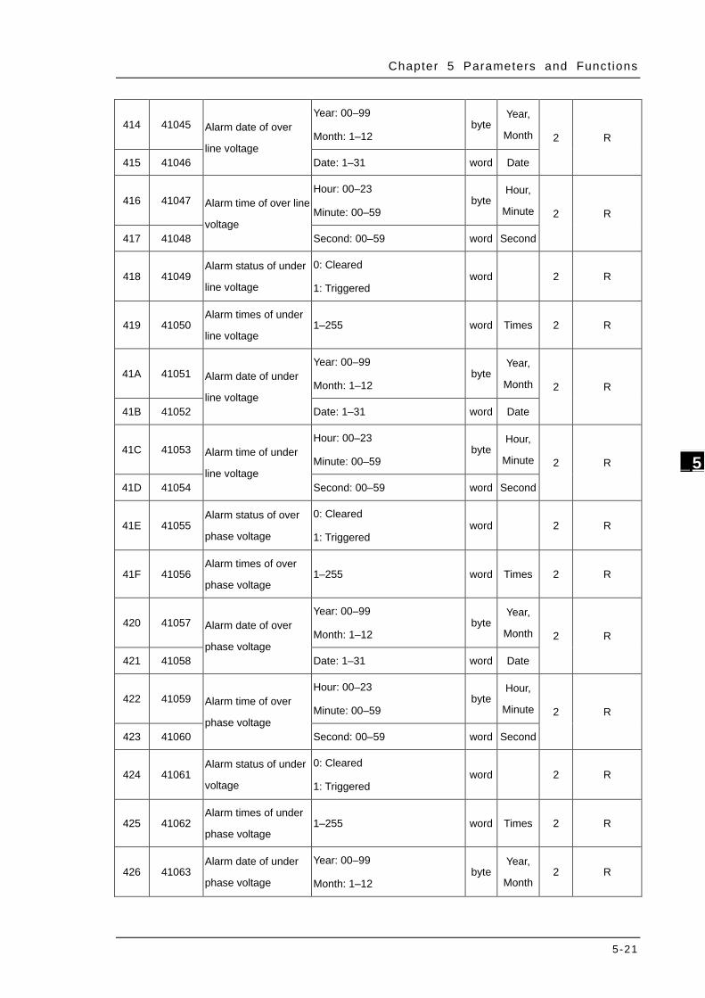
Chapter 5 Parameters and Funct ions
5-21
_5
414 41045 Alarm date of over
line voltage
Year: 00–99
Month: 1–12 byte
Year,
Month 2 R
415 41046 Date: 1–31 word Date
416 41047 Alarm time of over line
voltage
Hour: 00–23
Minute: 00–59 byte
Hour,
Minute 2 R
417 41048 Second: 00–59 word Second
418 41049 Alarm status of under
line voltage
0: Cleared
1: Triggered word
2 R
419 41050 Alarm times of under
line voltage 1–255 word Times 2 R
41A 41051 Alarm date of under
line voltage
Year: 00–99
Month: 1–12 byte
Year,
Month 2 R
41B 41052 Date: 1–31 word Date
41C 41053 Alarm time of under
line voltage
Hour: 00–23
Minute: 00–59 byte
Hour,
Minute 2 R
41D 41054 Second: 00–59 word Second
41E 41055 Alarm status of over
phase voltage
0: Cleared
1: Triggered word
2 R
41F 41056 Alarm times of over
phase voltage 1–255 word Times 2 R
420 41057 Alarm date of over
phase voltage
Year: 00–99
Month: 1–12 byte
Year,
Month 2 R
421 41058 Date: 1–31 word Date
422 41059 Alarm time of over
phase voltage
Hour: 00–23
Minute: 00–59 byte
Hour,
Minute 2 R
423 41060 Second: 00–59 word Second
424 41061 Alarm status of under
voltage
0: Cleared
1: Triggered word
2 R
425 41062 Alarm times of under
phase voltage 1–255 word Times 2 R
426 41063 Alarm date of under
phase voltage
Year: 00–99
Month: 1–12 byte
Year,
Month 2 R
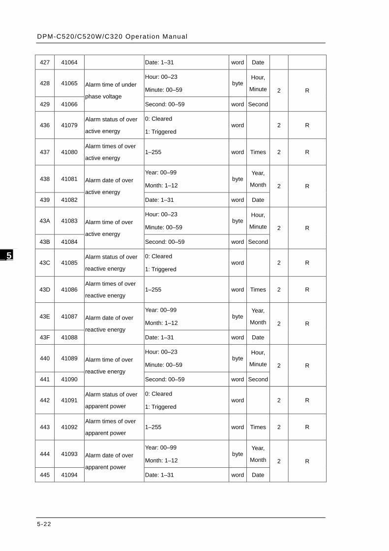
DPM-C520/C520W/C320 Operat ion Manual
5-22
_5
427 41064 Date: 1–31 word Date
428 41065 Alarm time of under
phase voltage
Hour: 00–23
Minute: 00–59 byte
Hour,
Minute 2 R
429 41066 Second: 00–59 word Second
436 41079 Alarm status of over
active energy
0: Cleared
1: Triggered word
2 R
437 41080 Alarm times of over
active energy 1–255 word Times 2 R
438 41081 Alarm date of over
active energy
Year: 00–99
Month: 1–12 byte
Year,
Month 2 R
439 41082 Date: 1–31 word Date
43A 41083 Alarm time of over
active energy
Hour: 00–23
Minute: 00–59 byte
Hour,
Minute 2 R
43B 41084 Second: 00–59 word Second
43C 41085 Alarm status of over
reactive energy
0: Cleared
1: Triggered word
2 R
43D 41086 Alarm times of over
reactive energy 1–255 word Times 2 R
43E 41087 Alarm date of over
reactive energy
Year: 00–99
Month: 1–12 byte
Year,
Month 2 R
43F 41088 Date: 1–31 word Date
440 41089 Alarm time of over
reactive energy
Hour: 00–23
Minute: 00–59 byte
Hour,
Minute 2 R
441 41090 Second: 00–59 word Second
442 41091 Alarm status of over
apparent power
0: Cleared
1: Triggered word
2 R
443 41092 Alarm times of over
apparent power 1–255 word Times 2 R
444 41093 Alarm date of over
apparent power
Year: 00–99
Month: 1–12 byte
Year,
Month 2 R
445 41094 Date: 1–31 word Date
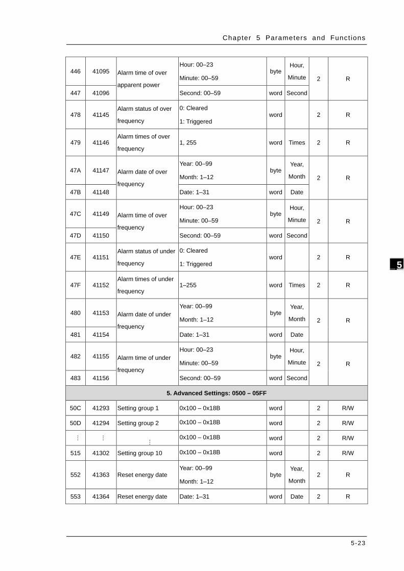
Chapter 5 Parameters and Funct ions
5-23
_5
446 41095 Alarm time of over
apparent power
Hour: 00–23
Minute: 00–59 byte
Hour,
Minute 2 R
447 41096 Second: 00–59 word Second
478 41145 Alarm status of over
frequency
0: Cleared
1: Triggered word
2 R
479 41146 Alarm times of over
frequency 1, 255 word Times 2 R
47A 41147 Alarm date of over
frequency
Year: 00–99
Month: 1–12 byte
Year,
Month 2 R
47B 41148 Date: 1–31 word Date
47C 41149 Alarm time of over
frequency
Hour: 00–23
Minute: 00–59 byte
Hour,
Minute 2 R
47D 41150 Second: 00–59 word Second
47E 41151 Alarm status of under
frequency
0: Cleared
1: Triggered word
2 R
47F 41152 Alarm times of under
frequency 1–255 word Times 2 R
480 41153 Alarm date of under
frequency
Year: 00–99
Month: 1–12 byte
Year,
Month 2 R
481 41154 Date: 1–31 word Date
482 41155 Alarm time of under
frequency
Hour: 00–23
Minute: 00–59 byte
Hour,
Minute 2 R
483 41156 Second: 00–59 word Second
5. Advanced Settings: 0500 – 05FF
50C 41293 Setting group 1 0x100 – 0x18B word 2 R/W
50D 41294 Setting group 2 0x100 – 0x18B word
2 R/W
…
…
… 0x100 – 0x18B word
2 R/W
515 41302 Setting group 10 0x100 – 0x18B word
2 R/W
552 41363 Reset energy date Year: 00–99
Month: 1–12 byte
Year,
Month 2 R
553 41364 Reset energy date Date: 1–31 word Date 2 R
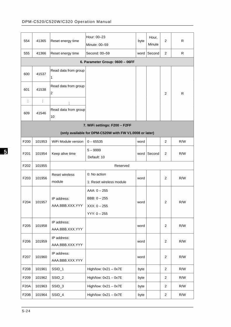
DPM-C520/C520W/C320 Operat ion Manual
5-24
_5
554 41365 Reset energy time Hour: 00–23
Minute: 00–59 byte
Hour,
Minute 2 R
555 41366 Reset energy time Second: 00–59 word Second 2 R
6. Parameter Group: 0600 – 06FF
600 41537 Read data from group
1
2 R 601 41538
Read data from group
2
…
…
…
609 41546 Read data from group
10
7. WiFi settings: F200 – F2FF
(only available for DPM-C520W with FW V1.0008 or later)
F200 101953 WiFi Module version 0 – 65535 word 2 R/W
F201 101954 Keep alive time 5 – 9999
Default: 10 word Second 2 R/W
F202 101955 Reserved
F203 101956 Reset wireless
module
0: No action
1: Reset wireless module word 2 R/W
F204 101957 IP address:
AAA.BBB.XXX.YYY
AAA: 0 – 255
BBB: 0 – 255
XXX: 0 – 255
YYY: 0 – 255
word 2 R/W
F205 101958 IP address:
AAA.BBB.XXX.YYY word 2 R/W
F206 101959 IP address:
AAA.BBB.XXX.YYY word 2 R/W
F207 101960 IP address:
AAA.BBB.XXX.YYY word 2 R/W
F208 101961 SSID_1 High/low: 0x21 – 0x7E byte 2 R/W
F209 101962 SSID_2 High/low: 0x21 – 0x7E byte 2 R/W
F20A 101963 SSID_3 High/low: 0x21 – 0x7E byte 2 R/W
F20B 101964 SSID_4 High/low: 0x21 – 0x7E byte 2 R/W
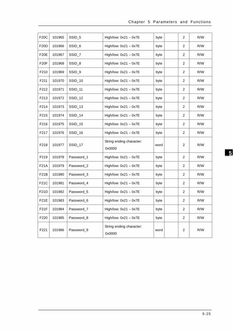
Chapter 5 Parameters and Funct ions
5-25
_5
F20C 101965 SSID_5 High/low: 0x21 – 0x7E byte 2 R/W
F20D 101966 SSID_6 High/low: 0x21 – 0x7E byte 2 R/W
F20E 101967 SSID_7 High/low: 0x21 – 0x7E byte 2 R/W
F20F 101968 SSID_8 High/low: 0x21 – 0x7E byte 2 R/W
F210 101969 SSID_9 High/low: 0x21 – 0x7E byte 2 R/W
F211 101970 SSID_10 High/low: 0x21 – 0x7E byte 2 R/W
F212 101971 SSID_11 High/low: 0x21 – 0x7E byte 2 R/W
F213 101972 SSID_12 High/low: 0x21 – 0x7E byte 2 R/W
F214 101973 SSID_13 High/low: 0x21 – 0x7E byte 2 R/W
F215 101974 SSID_14 High/low: 0x21 – 0x7E byte 2 R/W
F216 101975 SSID_15 High/low: 0x21 – 0x7E byte 2 R/W
F217 101976 SSID_16 High/low: 0x21 – 0x7E byte 2 R/W
F218 101977 SSID_17 String ending character:
0x0000 word 2 R/W
F219 101978 Password_1 High/low: 0x21 – 0x7E byte 2 R/W
F21A 101979 Password_2 High/low: 0x21 – 0x7E byte 2 R/W
F21B 101980 Password_3 High/low: 0x21 – 0x7E byte 2 R/W
F21C 101981 Password_4 High/low: 0x21 – 0x7E byte 2 R/W
F21D 101982 Password_5 High/low: 0x21 – 0x7E byte 2 R/W
F21E 101983 Password_6 High/low: 0x21 – 0x7E byte 2 R/W
F21F 101984 Password_7 High/low: 0x21 – 0x7E byte 2 R/W
F220 101985 Password_8 High/low: 0x21 – 0x7E byte 2 R/W
F221 101986 Password_9 String ending character:
0x0000 word 2 R/W
DPM-C520/C520W/C320 Operat ion Manual
5-26
_5
MEMO
6-1
Chapter 6 Error Codes
Table of Contents
6.1 Error Codes ......................................................................................... 6-2
6.2 Alarm Types ........................................................................................ 6-2
6
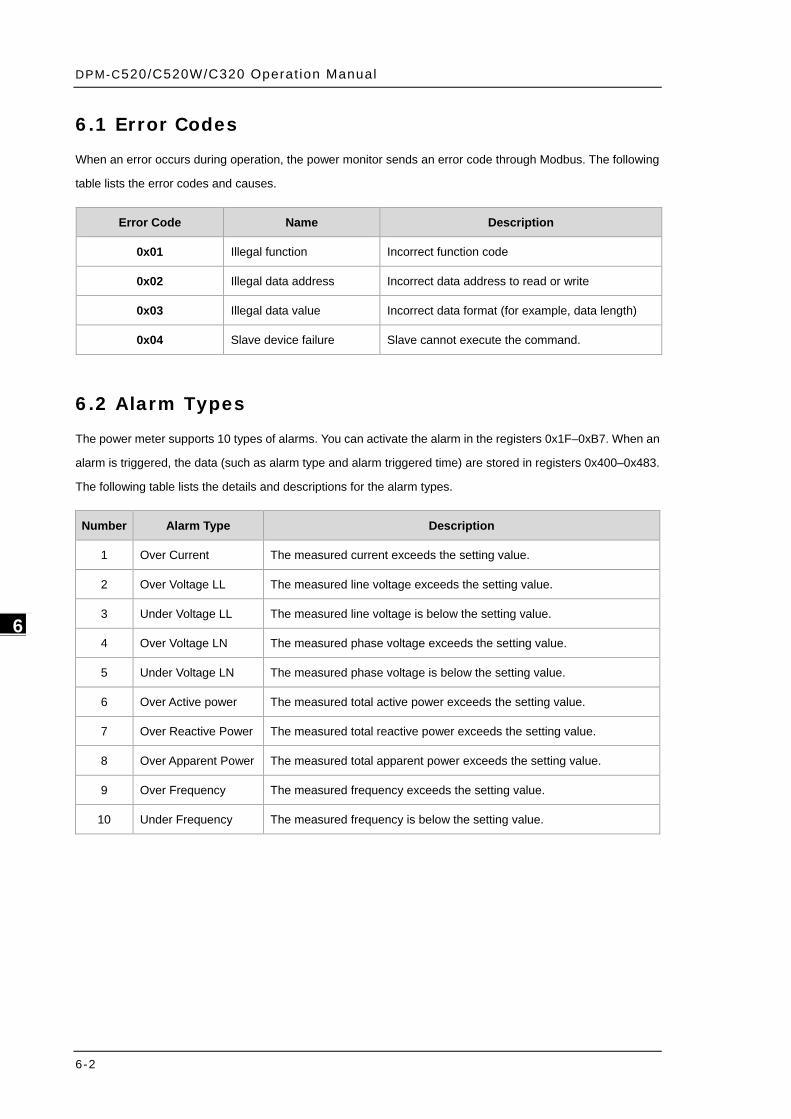
DPM-C520/C520W/C320 Operat ion Manual
6-2
_6
6.1 Error Codes
When an error occurs during operation, the power monitor sends an error code through Modbus. The following
table lists the error codes and causes.
Error Code Name Description
0x01 Illegal function Incorrect function code
0x02 Illegal data address Incorrect data address to read or write
0x03 Illegal data value Incorrect data format (for example, data length)
0x04 Slave device failure Slave cannot execute the command.
6.2 Alarm Types
The power meter supports 10 types of alarms. You can activate the alarm in the registers 0x1F–0xB7. When an
alarm is triggered, the data (such as alarm type and alarm triggered time) are stored in registers 0x400–0x483.
The following table lists the details and descriptions for the alarm types.
Number Alarm Type Description
1 Over Current The measured current exceeds the setting value.
2 Over Voltage LL The measured line voltage exceeds the setting value.
3 Under Voltage LL The measured line voltage is below the setting value.
4 Over Voltage LN The measured phase voltage exceeds the setting value.
5 Under Voltage LN The measured phase voltage is below the setting value.
6 Over Active power The measured total active power exceeds the setting value.
7 Over Reactive Power The measured total reactive power exceeds the setting value.
8 Over Apparent Power The measured total apparent power exceeds the setting value.
9 Over Frequency The measured frequency exceeds the setting value.
10 Under Frequency The measured frequency is below the setting value.
Α−1
Appendix A Accessories
Table of Contents
A.1 DCT1000 Series ................................................................................... A-2
A.2 DCT2000 Series ................................................................................... A-4
12 A
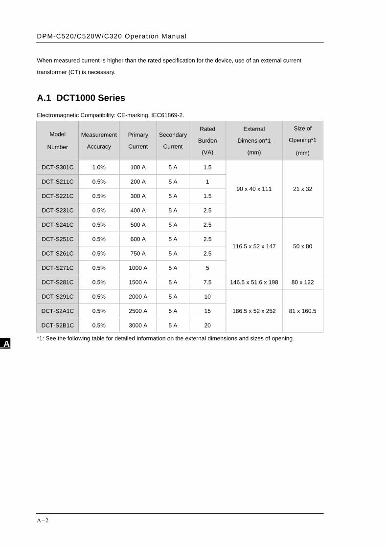
DPM-C520/C520W/C320 Operat ion Manual
Α−2
_A
When measured current is higher than the rated specification for the device, use of an external current
transformer (CT) is necessary.
A.1 DCT1000 Series Electromagnetic Compatibility: CE-marking, IEC61869-2.
Model
Number
Measurement
Accuracy
Primary
Current
Secondary
Current
Rated
Burden
(VA)
External
Dimension*1
(mm)
Size of
Opening*1
(mm)
DCT-S301C 1.0% 100 A 5 A 1.5
90 x 40 x 111 21 x 32 DCT-S211C 0.5% 200 A 5 A 1
DCT-S221C 0.5% 300 A 5 A 1.5
DCT-S231C 0.5% 400 A 5 A 2.5
DCT-S241C 0.5% 500 A 5 A 2.5
116.5 x 52 x 147 50 x 80 DCT-S251C 0.5% 600 A 5 A 2.5
DCT-S261C 0.5% 750 A 5 A 2.5
DCT-S271C 0.5% 1000 A 5 A 5
DCT-S281C 0.5% 1500 A 5 A 7.5 146.5 x 51.6 x 198 80 x 122
DCT-S291C 0.5% 2000 A 5 A 10
186.5 x 52 x 252 81 x 160.5 DCT-S2A1C 0.5% 2500 A 5 A 15
DCT-S2B1C 0.5% 3000 A 5 A 20
*1: See the following table for detailed information on the external dimensions and sizes of opening.

Appendix A Accessor ies
Α−3
A_
Model
Number Dimension (mm)
DCT-S301C External Dimension:
90 x 40 x 111
Size of Opening: 21 x 32
DCT-S211C
DCT-S221C
DCT-S231C
DCT-S241C External Dimension: 116.5
x 52 x 147
Size of Opening: 50 x 80
DCT-S251C
DCT-S261C
DCT-S271C
DCT-S281C
External Dimension: 146.5
x 51.6 x 198
Size of Opening: 80 x 122
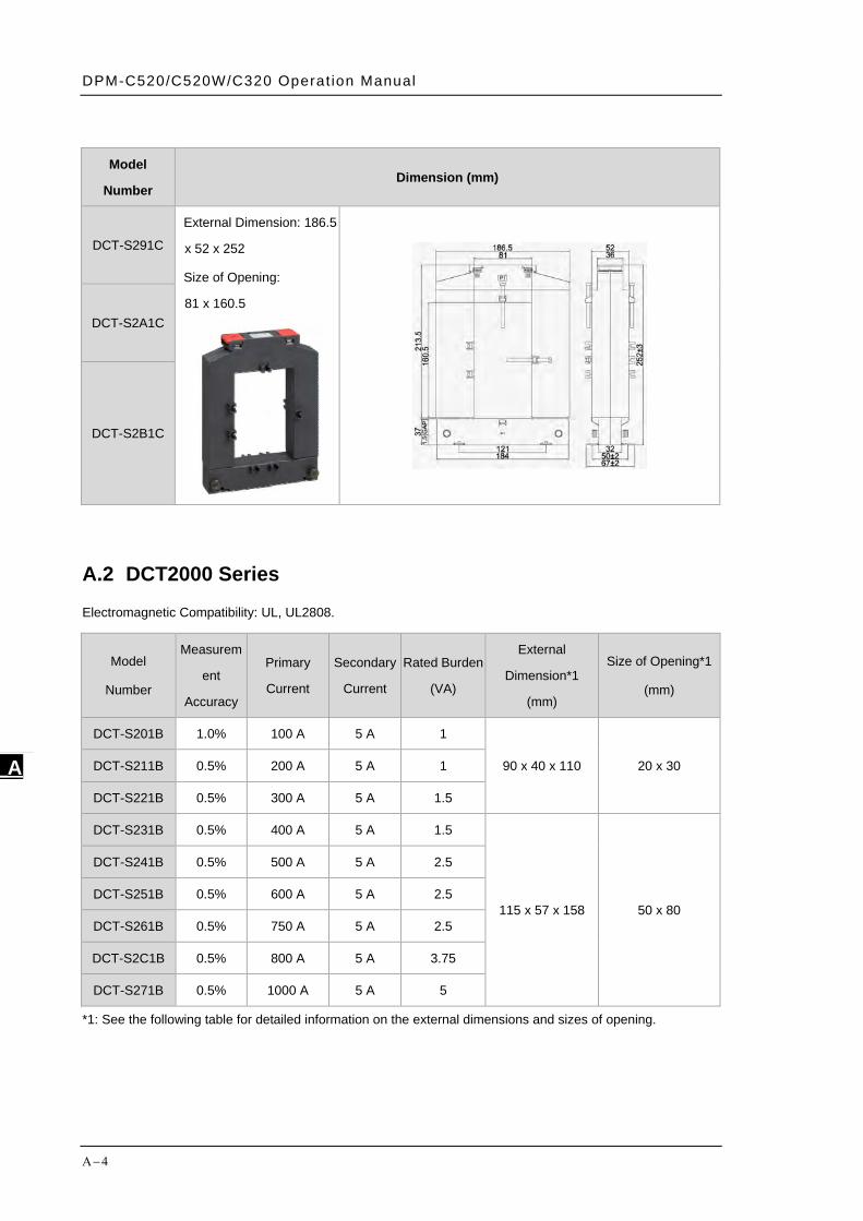
DPM-C520/C520W/C320 Operat ion Manual
Α−4
_A
Model
Number Dimension (mm)
DCT-S291C
External Dimension: 186.5
x 52 x 252
Size of Opening:
81 x 160.5
DCT-S2A1C
DCT-S2B1C
A.2 DCT2000 Series Electromagnetic Compatibility: UL, UL2808.
Model
Number
Measurem
ent
Accuracy
Primary
Current
Secondary
Current
Rated Burden
(VA)
External
Dimension*1
(mm)
Size of Opening*1
(mm)
DCT-S201B 1.0% 100 A 5 A 1
90 x 40 x 110 20 x 30 DCT-S211B 0.5% 200 A 5 A 1
DCT-S221B 0.5% 300 A 5 A 1.5
DCT-S231B 0.5% 400 A 5 A 1.5
115 x 57 x 158 50 x 80
DCT-S241B 0.5% 500 A 5 A 2.5
DCT-S251B 0.5% 600 A 5 A 2.5
DCT-S261B 0.5% 750 A 5 A 2.5
DCT-S2C1B 0.5% 800 A 5 A 3.75
DCT-S271B 0.5% 1000 A 5 A 5
*1: See the following table for detailed information on the external dimensions and sizes of opening.
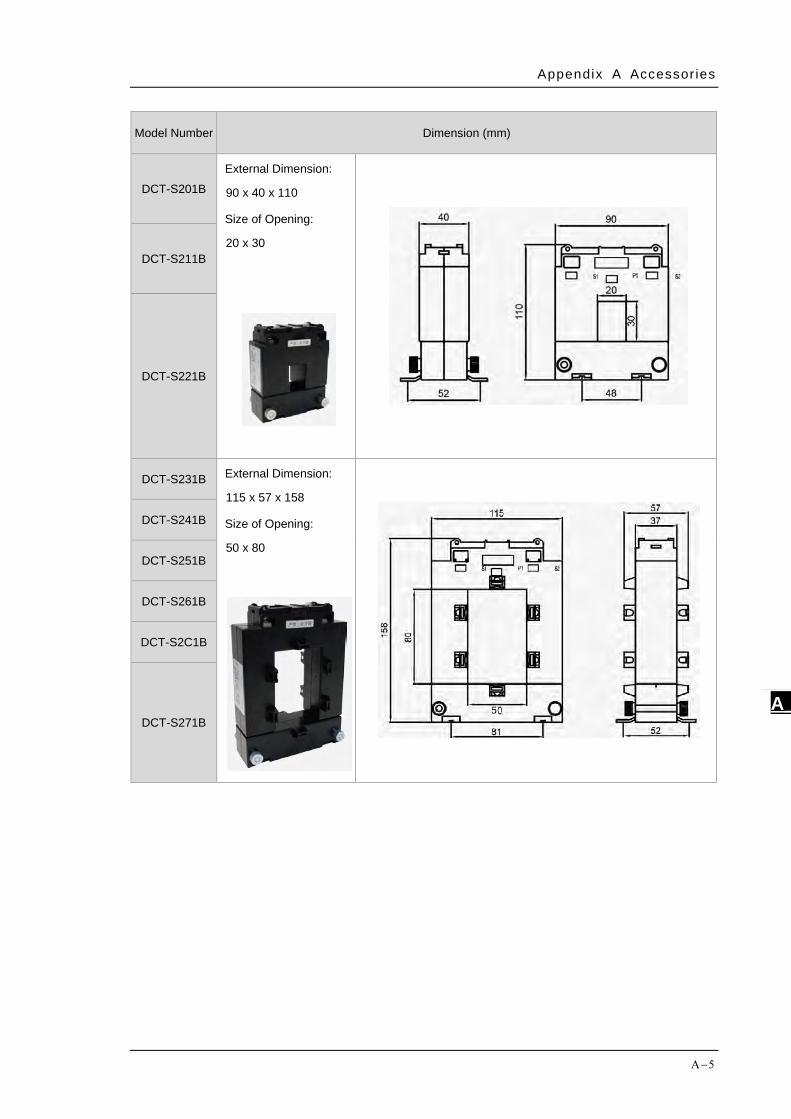
Appendix A Accessor ies
Α−5
A_
Model Number Dimension (mm)
DCT-S201B External Dimension:
90 x 40 x 110
Size of Opening:
20 x 30
DCT-S211B
DCT-S221B
DCT-S231B External Dimension:
115 x 57 x 158
Size of Opening:
50 x 80
DCT-S241B
DCT-S251B
DCT-S261B
DCT-S2C1B
DCT-S271B

DPM-C520/C520W/C320 Operat ion Manual
Α−6
_A
MEMO