multi-layer precoding: a potential solution for full...
TRANSCRIPT

Ahmed Alkhateeb, Geert Leus*, and Robert W. Heath Jr
Wireless Networking and Communications Group Department of Electrical and Computer Engineering
The University of Texas at Austin
*Delft University of Technology Faculty of EE., Mathematics and Computer Science
Multi-Layer Precoding: A Potential Solution for Full-Dimensional Massive MIMO Systems

OutlineIntroductionSystem and Channel ModelsMulti-Layer Precoding DesignPerformance Results
2

mmWave systems Large arrays are needed at transmitter & receiver
Leverage large available bandwidth at high frequency
Enable very high data rates
Massive MIMO gainsLarge numbers of users are simultaneously served
High sum-rates
Simplified multi-user processing
Small transmit power
MIMO is Big!
3
Why not we keep scaling MIMO up?
Ba

Interference Management is Challenging
Need high channel state information (CSI)Large channel dimensions
Large amount of pilots
Basestation cooperation overhead
4
How to manage the interference with limited channel knowledge?
Bas Bas
Bas
MU interference
Inter-cell interference
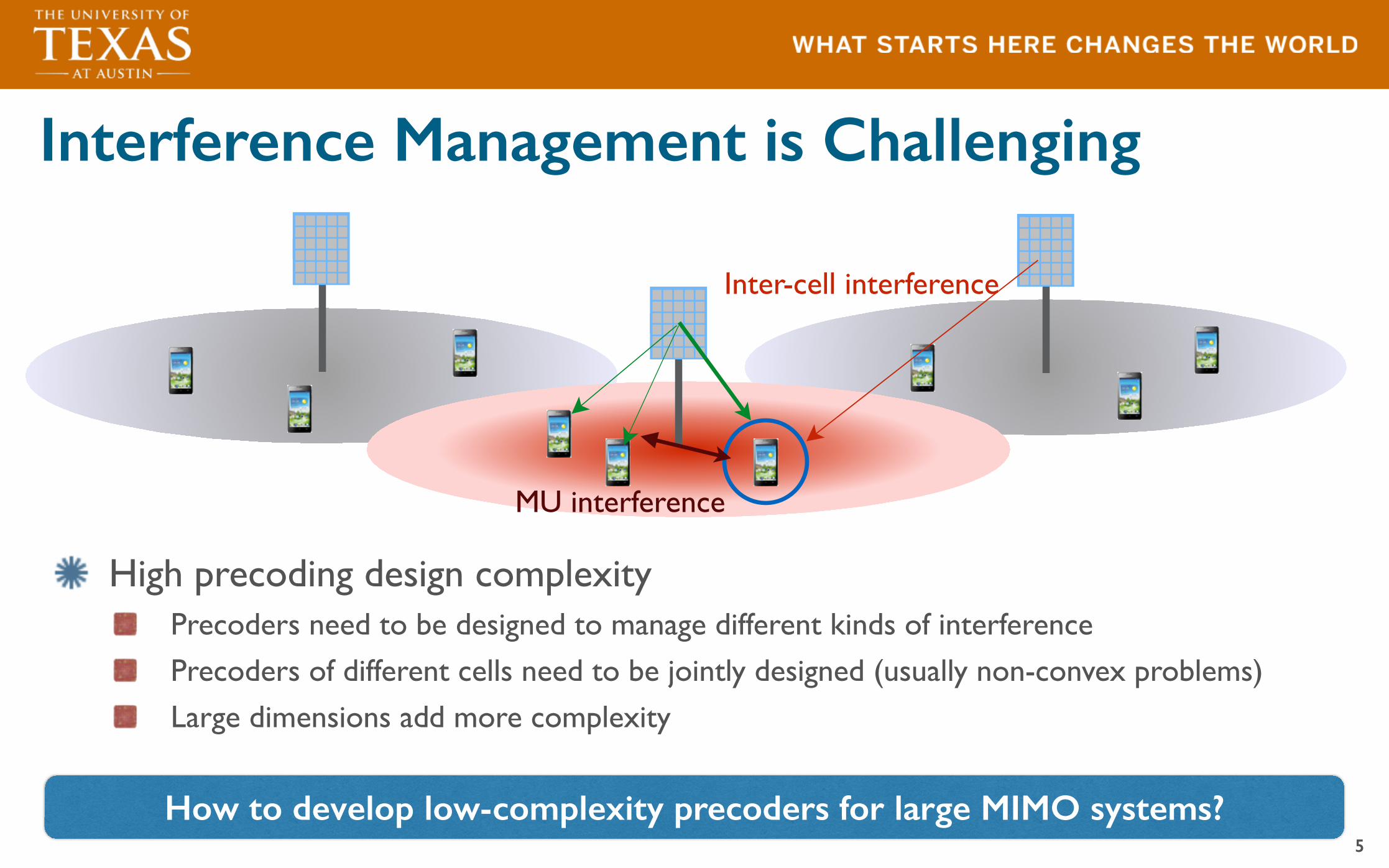
Interference Management is Challenging
High precoding design complexityPrecoders need to be designed to manage different kinds of interference
Precoders of different cells need to be jointly designed (usually non-convex problems)
Large dimensions add more complexity
5
How to develop low-complexity precoders for large MIMO systems?
Bas Bas
Bas
MU interference
Inter-cell interference

Multi-Layer Precoding: A Potential Solution
Decoupling of Precoding Objectives Each precoding layer (matrix) is responsible of one objective
Dependence on large channel statisticsEach precoding layer depends on channel statistics larger (slower) than next layers
6
Ba
Ba
MU interference
Inter-cell interference
Multi-Layer Precoding for Full-DimensionalMassive MIMO Systems
Ahmed Alkhateeb†, Geert Leus‡, and Robert W. Heath Jr.†† The University of Texas at Austin, TX, USA, Email: {aalkhateeb, rheath}@utexas.edu
‡ Delft University of Technology, The Netherlands, Email: [email protected]
Abstract—Full-dimensional massive multiple-input multiple-output (MIMO) systems boost spectral efficiency by offeringorders of magnitude increase in multiplexing gains. Increasingthe number of antennas, however, face two main challenges:(i) Challenges associated with the large-dimensional channels,which lead to a large feedback overhead in frequency divisionduplexing systems and the pilot contamination effect in timedivision douplexing systems, and (ii) challenges related to theimplementation of large antenna arrays. In this paper, we proposethe multi-layer precoding, a potential solution to address thesechallenges in massive MIMO systems. Multi-layer precoding(i) enables leveraging the directional characteristics of large-scale MIMO channels to manage inter-cell interference with lowchannel requirements, and (ii) allows for an efficient implemen-tation using low-complexity hybrid analog/digital architectures.We present and evaluate a specific multi-layer precoding designfor full-dimensional massive MIMO systems. Simulation resultsshow the potential gains of multi-layer precoding compared withtraditional pilot-contaminated massive MIMO setups despite thelow channel knowledge requirements and the low-complexityimplementation.
I. INTRODUCTION
Full-dimensional massive MIMO promises significant gainsfor cellular systems. Scaling up the number of antennas,however, faces a number of challenges that prevent the corre-sponding scaling of the gains. The large-dimensional channelshave high feedback overheads in frequency division duplexing(FDD) systems. To overcome that, channel reciprocity intime division douplexing (TDD) systems was leveraged. Theperformance of TDD massive MIMO systems, however, islimited at large number of antennas by the pilot contaminationimpact, which is a sort of inter-cell interference. Handlinginter-cell interference using traditional network MIMO tech-niques is associated with high coordination overheads. Anotherchallenge with the large number of antennas lies in the hard-ware implementation. Traditional MIMO precoding techniquesgenerally assumes that the processing is done in the baseband.This, however, assumes the dedication of a separate RF chainper antenna, which is difficult to achieve with large numbersof antennas. Therefore, developing precoding schemes that canovercome these challenges is of great interest.
Motivated by the hardware limitations on the RF chainsin millimeter wave (mmWave) large antenna systems, [?], [?]proposed to divide the precoding processing between analogand digital domain, known as hybrid analog/digital precoding.In [?] and [?], low-complexity hybrid analog/digital precodingalgorithms were developed for single-user and multi-user sys-
tems, exploiting the sparse-nature of mmWave channels. Thesealgorithms, however, did not account for out-of-cell interfer-ence. In another research direction, [?] proposed the joint-spatial division multiplexing (JSDM) scheme, with the aimof reducing the channel feedback overhead in FDD massiveMIMO systems. In JSDM scheme, the basestation (BS) dividesthe mobile stations (MS’s) into groups of approximately sim-ilar covariance eigenspaces, and designs a pre-beamformingmatrix based on the large channel statistics. The interferencebetween the group users is then managed using anotherprecoding matrix given the effective reduced-dimension chan-nels. The work in [?], however, did not consider out-of-cellinterference. In [?], the directional characteristics of large-dimensional channels were leveraged to improve the uplinkchannel training in TDD systems, with the knowledge ofthe interference covariance matrix. [?] though did not targetcertain precoding designs, and therefore did not account forthe hardware constraints.
In this paper, we introduce the general concept of multi-layer precoding, a potential solution for massive MIMOsystems that (i) enables inter-cell interference managementusing large-scale channel statistics, and (ii) allows for efficientimplementation using hybrid analog/digital architecture witha relatively small number of RF chains. For FD massiveMIMO systems, we propose and evaluate a specific multi-layerprecoding design that leverages the low-rank property of theelevation covariance matrix and the directional characteristicof large-dimensional channels to realize a low-complexity so-lution. The proposed scheme is also evaluated by simulationsin a cellular setup where a noticeable coverage gain was showncompared with pilot-contaminated traditional massive MIMOsolutions.
II. SYSTEM MODEL
F = F(1)F(2)F(3) (1)
Consider a cellular system model consisting of L cells withone BS and K MS’s in each cell, as shown in Fig. ??. EachBS is equipped with a two-dimensional (2D) antenna array ofNV (vertical antennas) ⇥NH (horizontal antennas), and eachMS has a single antenna. We assume that all BS’s and MS’sare synchronized and operate a TDD protocol with universalfrequency reuse. In the downlink, each BS `, ` = 1, 2, ..., L,applies a NVNH ⇥ K precoder F` = [f`1, f`2, ..., f`K ] to
Inter-cell interference management
Desired signal optimization
Multi-userinterference management
Low-complexity design
Requires limited CSI

Connection to Prior WorkMulti-user hybrid analog/digital precoding [1]
Motivated mainly by hardware constraints
Leverages the sparse nature of mmWave channels
Did not consider out-of-cell interference
Joint spatial-division multiplexing [2]Motivated by large channel feedback overhead in FDD
Groups the users based on their channel covariance
Did not consider out-of-cell interference
Pilot decontamination for massive MIMO [3]Leverages the low-dimensional interference subspace to get better desired channel estimate
Considered 1-D antenna arrays
Requires the knowledge of the interference covariance matrices
7
[1] A. Alkhateeb, G. Leus, and R. W. Heath Jr, “Limited feedback hybrid precoding for multi-user millimeter wave systems,” submitted to IEEE Trans. on Wireless Commu, arXiv:1409.5162, 2014.[2] A. Adhikary, J. Nam, J.-Y. Ahn, and G. Caire, “Joint spatial division and multiplexing: The large-scale array regime,” IEEE Trans. of IT., vol. 59, no. 10, pp. 6441–6463, October 2013.[3] Y. Haifan, D. Gesbert, M. Filippou, Y. Liu, "A Coordinated Approach to Channel Estimation in Large-Scale Multiple-Antenna Systems," IEEE JSAC, vol.31, no.2, pp.264,273, February 2013
Ba

System Model
BS has a 2D antenna array of NV vertical elements x NH horizontal elements
K single-antenna users are simultaneously served in each cell All BS’s are assumed to be synchronized - TDD - Universal frequency reuseIn the downlink, precoder is used by BS cReceived signal by user k in cell c
8
Base Base
L cells
MS’s per cell
MS k
antennas at the BS

Channel ModelKronecker product correlation [1]
Using Karhunen-Loeve representation [2]
Assuming rank-1 elevation correlation [3]
9
Bas
Higher scattering in the street level[1] Ying D, Nam J, Vook FW, Thomas TA, Love DJ, Ghosh A: Kronecker product correlation model and limited feedback codebook design in a 3d channel model. In Proc. IEEE International Conference on Communications. Sydney; 10–14 June 2014.[2] A. Adhikary, J. Nam, J.-Y. Ahn, and G. Caire, “Joint spatial division and multiplexing: The large-scale array regime,” IEEE Transactions on Information Theory, vol. 59, no. 10, pp. 6441–6463, October 2013.[3] Z. Zhong, X. Yin, X. Li, and X. Li, “Extension of ITU IMTadvanced channel models for elevation domains and line-of-sight scenarios,” in Proceedings of the 78th IEEE Vehicular Technology Conference (VTC ’13), pp. 1–5, Las Vegas, Nev, USA, September 2013.
Elevation correlationAzimuth correlation

Insights from Large Channel CharacteristicsChannel covariance matrices have directional structure [1], [2]
10
In the elevation direction, signal and interference may occupy different subspaces
Signal and interference are contained in low-dimensional subspaces
Ba BaInterference subspace
Cell c
[1] Y. Haifan, D. Gesbert, M. Filippou, Y. Liu, "A Coordinated Approach to Channel Estimation in Large-Scale Multiple-Antenna Systems," IEEE JSAC , vol.31, no.2, pp.264,273, February 2013[2] Z. Zhong, X. Yin, X. Li, and X. Li, “Extension of ITU IMTadvanced channel models for elevation domains and line-of-sight scenarios,” in Proceedings of the 78th IEEE Vehicular Technology Conference (VTC ’13), pp. 1–5, Las Vegas, Nev, USA, September 2013.

Multi-Layer Precoding Design (1/3)The SINR of user k in cell c is
In the designLeverage the Kronecker structure of the channel
Focus on multi-layer precoding in the elevation direction
11
Desired signal power
Inter-cell interferenceMulti-user interference
Minimize inter-cell interferenceRequires large-scale channel statistics
Maximize effective signal powerRequires large-scale channel statistics
Minimize multi-user interferenceRequires instantaneous channel

Multi-Layer Precoding Design (2/3)First layer:
To avoid inter-cell interference, is designed such that
After the first layer
12
Inter-cell interference
Expectation over different scheduled users
Interference null-space
B BInterference subspace
Intuition
Cell c
Time
Due to the expectation

Multi-Layer Precoding Design (3/3)Second layer
Training: Acquires effective channel elevation covariance eigenvectors (reduced rank)
Remark: No uplink inter-cell interference during training phase due to first layer
After the second layer
Third layerTraining: Instantaneous effective channels (reduced-rank channel)
After the third layer
13
Conjugate beamforming of the effective channel covariance
Effective channel is of K x K dimensions
Penalty of interference management

Achievable RatesAssume The achievable rate of user k in cell c
with
Asymptotic optimality
Performance approaches single-user rate
14
Assumption 1: The eigenvectors of the signal and inter-ference elevation channel covariance matrices of each cell csatisfy
• ucck 2 R�UNI
c
�, 8k
• uc`k 2 R�UNI
c
�?, 8k, 8` 6= c
Note that this decoupling assumption is a good assumptionat large numbers of vertical antennas NV.
Proposition 2: Consider the system model in Section II,and Assumption 1, the achievable rate of user k in cell cwhen the multi-layer precoding scheme in Section IV is usedto construct the BS downlink precoders is lower bounded by
Rck � log2
✓1 +
PkhAcckk2�cck
�2G�Uc
�◆, (15)
where G�Uc
�= 4
✓�2
max
(
Uc)
�2
min
(
Uc)+
�2
min
(
Uc)
�2
max
(
Uc)+ 2
◆�1
, with
�max
�Uc
�and �min
�Uc
�the maximum and minimum sin-
gular values of Uc.Proof: Consider the system model in Section II, and
the multi-layer precoding scheme in Section IV, then thereceived signal at user k of cell c is given by (14). Further,under Assumption 1, the approximation sign in (12) becomesequality and we get
yck = khAcckk [⌥c]k,k [sc]k + nck, (16)
by which the achievable rate of user k in cell c will be
Rck = log2
✓1 +
PkhAcckk2
�2[⌥c]
2k,k
◆. (17)
The value of [⌥c]k,k is adjusted to satisfy the precodingpower constraint k [Fc]:,k k2 = 1. Using a similar analysis to
that in Appendix A of [2], we get [⌥c]k,k =
r�cck
(
U⇤cUc)
�1
k,k
,
where the matrix U⇤cUc can be further proved to be a positive
semi-definite matrix with probability 1 using a similar proofto Lemma 2 in [2]. Hence, according to Lemma 3 in [2]⇣U
⇤cUc
⌘�1
k,k 1
4
�2max
�Uc
�
�2min
�Uc
�+
�2min
�Uc
�
�2max
�Uc
�+ 2
!(18)
In addition to characterizing a lower bound on the achiev-able rates by the proposed precoding scheme, the bound in (15)separates the dependence on the channel gain �cck, and thechannel eigenspace, which is used by the following corollaryto claim the asymptotic optimality of the proposed scheme.
Corollary 3: Let ˚Rck = log2
⇣1 +
PkhA
cckk2�cck
�2
⌘denote
the single-user rate of user k in cell c. With the multi-layerprecoding scheme in Section IV, and given Assumption 1, theachievable rate by any user k in cell c satisfies
lim
NV
!1r/N
V
=const.
Rck =
˚Rckwith probability one. (19)
The proof is similar to that in Appendix B of [2]. Corollary 3indicates that as the number of vertical antennas increases, the
achievable rate of the proposed multi-layer precoding schemeunder Assumption 1 approaches the single-user rate, i.e., theinter-cell and multi-user interference vanish. Further, with alarge number of antennas, the decoupling assumption (As-sumption 1) becomes valid with high probability thanks to thedirectional structure of large-scale MIMO channels, as will beshown by simulations in Section VII. This illustrates how theproposed multi-layer precoding enables inter-cell interferencemanagement with low channel knowledge requirements.
VI. HYBRID ANALOG/DIGITAL IMPLEMENTATION
Thanks to the multiplicative structure and the specific designof the multi-layer precoding in Section IV, we note that eachprecoding layer has less dimensions compared with the priorlayers. This allows the multi-layer precoding matrix to beimplemented using a small number of RF chains with a hybridanalog/digital precoding architecture [2]. In this section, webriefly highlight the main idea of the hybrid analog/digitalimplementation.
Considering the elevation multi-layer precoding matrixFE
c = FEc(1)
FEc(2)
FEc(3), we note that the dimensions of FE
c(3)
are K⇥K. Hence, if FEc(1) and FE
c(2) are implemented using
analog hardware, and FEc(3) is implemented in the baseband,
we will need only K RF chains. To do that, we propose toleverage the downtilt directional antenna patterns included inthe ITU channel models [6]. We assume that each antenna is anantenna port with a directional pattern and electrically adjusteddowntilt angle [6], [9]. The 3GPP antenna port elevation gainGE
(✓) is defined as [6]
GE(✓) = GE
max �min
(12
✓✓ � ✓tilt✓3dB
◆2
, SL
), (20)
where ✓tilt is the downtilt angle, and SL is the sidelobe level.Therefore, one way to approximate FE
c(1) is to adjust the
downtilt angle ✓tilt to force the transmission to be in theinterference null-space UNI
c .Once FE
c(1) is implemented, the second and third layers,
FEc(2)
,FEc(3), can be approximated exactly as proposed in [2],
i.e., each one of the K columns of FEc(2) can be approximated
by a beamsteering vector taken from a codebook that capturesthe analog hardware constraints, and the K⇥K matrix FE
c(3)
is implemented in the baseband to manage the multi-userinterference based on the effective channel that includes theeffect of the first and second precoding layers.
VII. SIMULATION RESULTS
In this section, we evaluate the performance of the proposedmulti-layer precoding scheme. First, we consider the single-cell setup of a BS with a 2D antenna array serving K = 4 usersin Fig. 2. The channels are assumed to have the Kroneckermodel in (4), with IID Rayleigh azimuth channel vectors,rank-one elevation channels, and SNR=0 dB. Fig. 2 showsthe achievable rate of the proposed multi-layer precodingscheme with different numbers of BS antennas. It illustratesthat the achievable rate approaches the single-user rate with
and

Simulation Results
Considerable gains compared with interference-limited massive MIMO systemsGains are mainly due to inter-cell interference managementGains increase with the number of antennas Very close performance to the case with exact interference covariance matrixCell edge users may be blocked if the number of antennas is not large enough
15
Setup: Poisson layout of BS’s and MS’sMS poisson density is 30 times higher than BS densitiesInter-site distance=200 m, antenna height=50 mMS’s are associated to the nearest BSBS randomly selects K=4 MS’s to be servedPerformance is averaged over100 realizations Interference covariance is averaged over 20 realizationsPathloss exponent=3.5
Ba
Ba
Ba
Ba
Multi-layer precoding gain
Small difference between exact and
approx. int. covariance knowledge

Conclusion and Future WorkMulti-layer precoding
Manages inter-cell and multi-user interference
Requires limited channel knowledge
Enables low-complexity designs (precoding objectives decoupling)
Approaches the single-user rates in some special cases
Future extensions Performance analysis for more general channel settings, e.h., including angle spread
Investigating solutions to improve cell-edge users in the non-asymptotic regime
Evaluating the impact of channel estimation errors
Approximation using hybrid analog/digital architecture
16
Ahmed Alkhateeb, Geert Leus, and Robert W. Heath Jr, "Multi-Layer Precoding for Full-Dimensional Massive MIMO Systems," in Proc. of Asilomar Conference on Signals, Systems and Computers , Pacific Grove, CA, November 2014.

Questions?
17
Ahmed Alkhateeb The University of Texas at Austin
Thank You