multi-physics design optimization of an axial …© 2011 ansys, inc. december 11, 2012 1 johannes...
TRANSCRIPT
© 2011 ANSYS, Inc. December 11, 2012
1
Johannes Einzinger, ANSYS
Multi-Physics Design Optimization of an Axial Compressor
Application and Best-Practice Guide-Lines
© 2011 ANSYS, Inc. December 11, 2012
2
Overview

© 2011 ANSYS, Inc. December 11, 2012
4
Application Overview

© 2011 ANSYS, Inc. December 11, 2012
5
Geometry, Aero Dynamic
• Camber/Thickness for
• IGV, R1, S1; 2-3 Layers
• 5 βi per Layer, 3xThk
• Hub, 8 radii (const. Shroud)
• 47 CAD Input Parameter

© 2011 ANSYS, Inc. December 11, 2012
6
CFD Simulation
• CFD Solver: CFX
• Nodal based FVM
• Coupled Solution + AMG
• Mass & Momentum, Energy…
• Turbulence Model:
• Shear Stress Transport
Two sector by passage, MFR:
• Profile/Time Transformation
• Periodic Interface
V A A V
V A AdV d d S dVt
© 2011 ANSYS, Inc. December 11, 2012
7
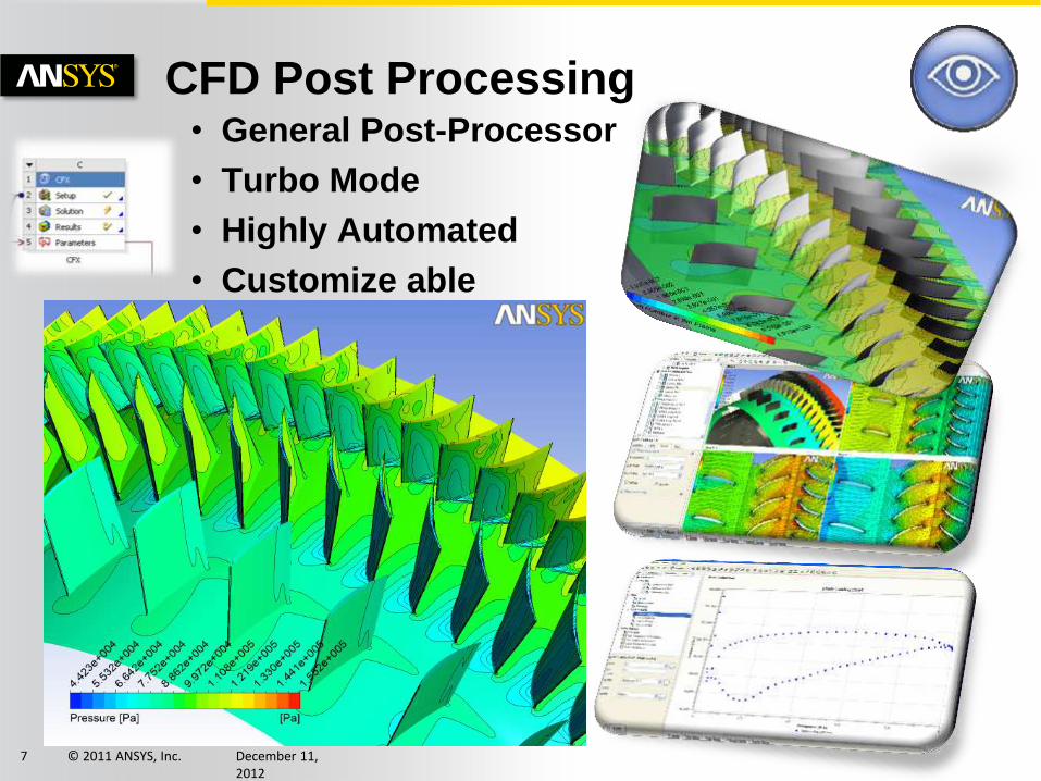
CFD Post Processing • General Post-Processor
• Turbo Mode
• Highly Automated
• Customize able
© 2011 ANSYS, Inc. December 11, 2012
8
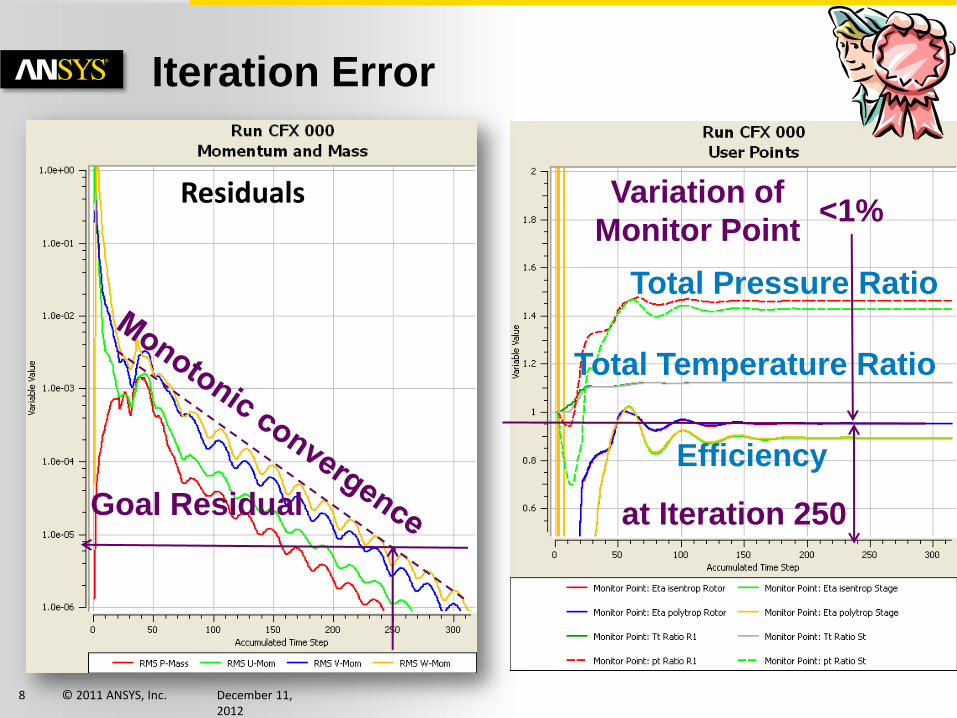
Iteration Error
<1% Variation of
Monitor Point
at Iteration 250 Goal Residual
Residuals
Total Pressure Ratio
Efficiency
Total Temperature Ratio
© 2011 ANSYS, Inc. December 11, 2012
9
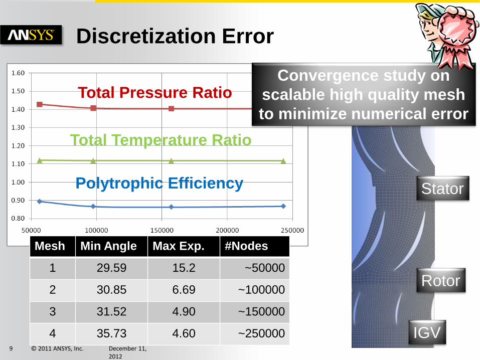
Discretization Error
Mesh Min Angle Max Exp. #Nodes
1 29.59 15.2 ~50000
2 30.85 6.69 ~100000
3 31.52 4.90 ~150000
4 35.73 4.60 ~250000
Convergence study on
scalable high quality mesh
to minimize numerical error
Rotor
Stator
IGV
Total Pressure Ratio
Total Temperature Ratio
Polytrophic Efficiency

© 2011 ANSYS, Inc. December 11, 2012
10
Model Error
• Steady vs. Transient
simulation
• Cold vs. hot geometry
• Turbulence Model: RANS
vs. Scale Resolved

© 2011 ANSYS, Inc. December 11, 2012
11
Static Structural (Pre-Stress)
• Static Solution:
• Displacement
• Strain & Stress
• Numerical Error
• Pre-Stress for
further Analysis
© 2011 ANSYS, Inc. December 11, 2012
12
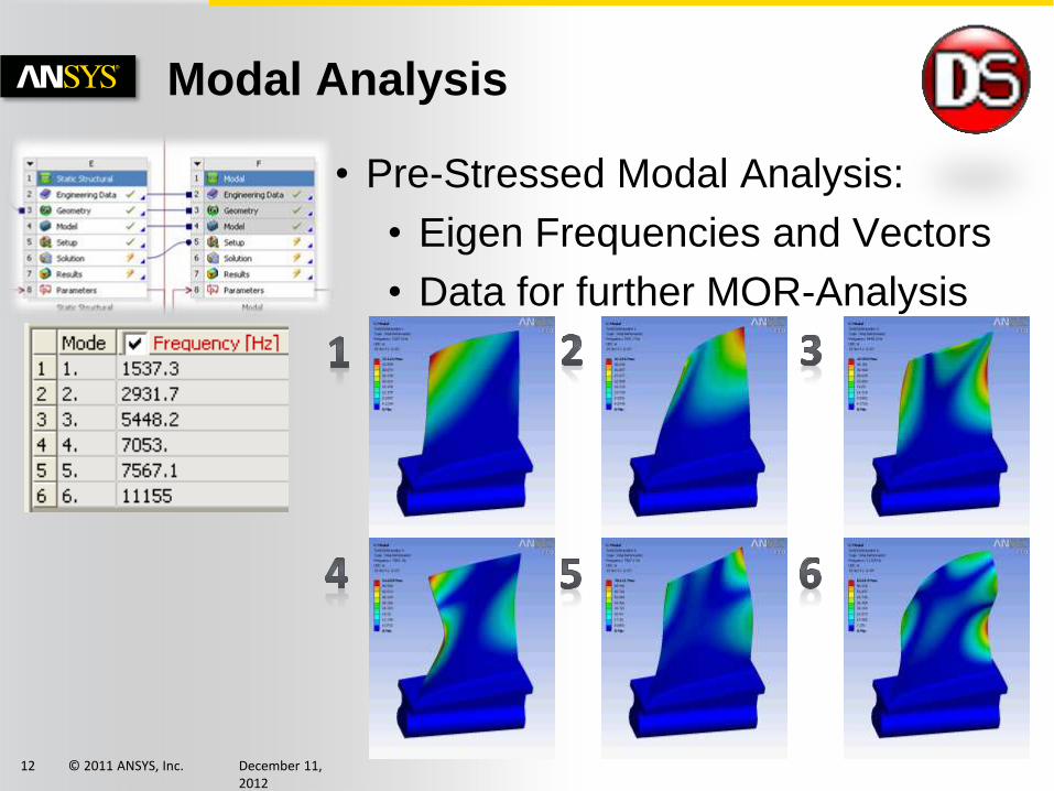
Modal Analysis
• Pre-Stressed Modal Analysis:
• Eigen Frequencies and Vectors
• Data for further MOR-Analysis
© 2011 ANSYS, Inc. December 11, 2012
13
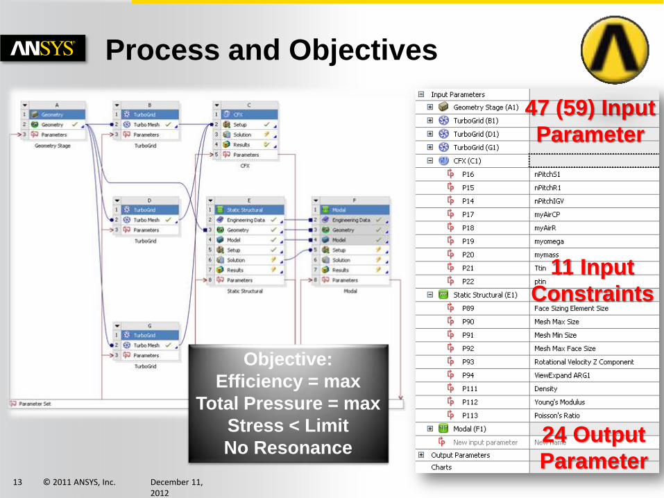
47 (59) Input
Parameter
24 Output
Parameter
Objective:
Efficiency = max
Total Pressure = max
Stress < Limit
No Resonance
Process and Objectives
11 Input
Constraints

© 2011 ANSYS, Inc. December 11, 2012
14
The Workbench Effect – easier to use
Easy parametric
set up of complex
simulations
Fully parametric
optiSLang inside Workbench
easy use of best praxis automated
flows inside Workbench
© 2011 ANSYS, Inc. December 11, 2012
15
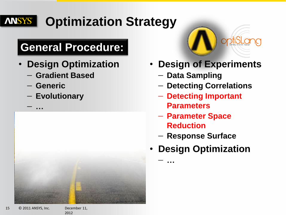
Optimization Strategy
• Design Optimization Gradient Based
Generic
Evolutionary
…
• Design of Experiments Data Sampling
Detecting Correlations
Detecting Important
Parameters
Parameter Space
Reduction
Response Surface
• Design Optimization …
General Procedure:

© 2011 ANSYS, Inc. December 11, 2012
16
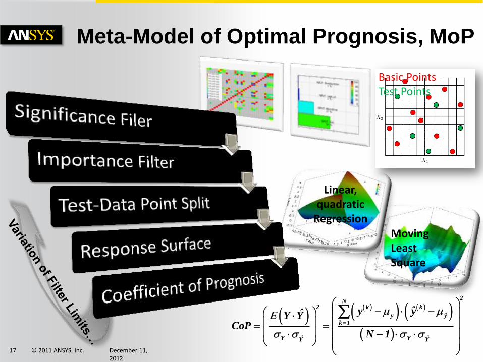
• Correlation Filter
• Importance Filter (CoI)
• Remaining parameters are used
for non/linear approximation
• Basic Points for Approximation
• Test Points for Quality
Assurance
2N
k k2
ˆy y
k 1
ˆ ˆY YY Y
ˆy yˆY YCoP
N 1
Data-Split
Meta-Model of Optimal Prognosis, MoP
© 2011 ANSYS, Inc. December 11, 2012
17
Linear, quadratic
Regression Moving Least Square
Basic Points Test Points
Meta-Model of Optimal Prognosis, MoP
2N
k k2
ˆy y
k 1
ˆ ˆY YY Y
ˆy yˆY YCoP
N 1

© 2011 ANSYS, Inc. December 11, 2012
18
optiSLang Strategy
0%
100%
Co
eff
icie
nt
of
Pro
gn
osis
Quality of Response
Surface Approximation

© 2011 ANSYS, Inc. December 11, 2012
19
Maximal Stress
Blade Angle: Hub,
Mid Leading Edge
β
• CoP=86%
Statistic is reliable
Detect important Variables
Parameter Reduction
• MoP is plausible

© 2011 ANSYS, Inc. December 11, 2012
20
Aero Dynamic
• CoP=64% and 65%
small value
Numerical error?
Model error?
• Important Variables
Parameter Reduction
• MoP is plausible
© 2011 ANSYS, Inc. December 11, 2012
21
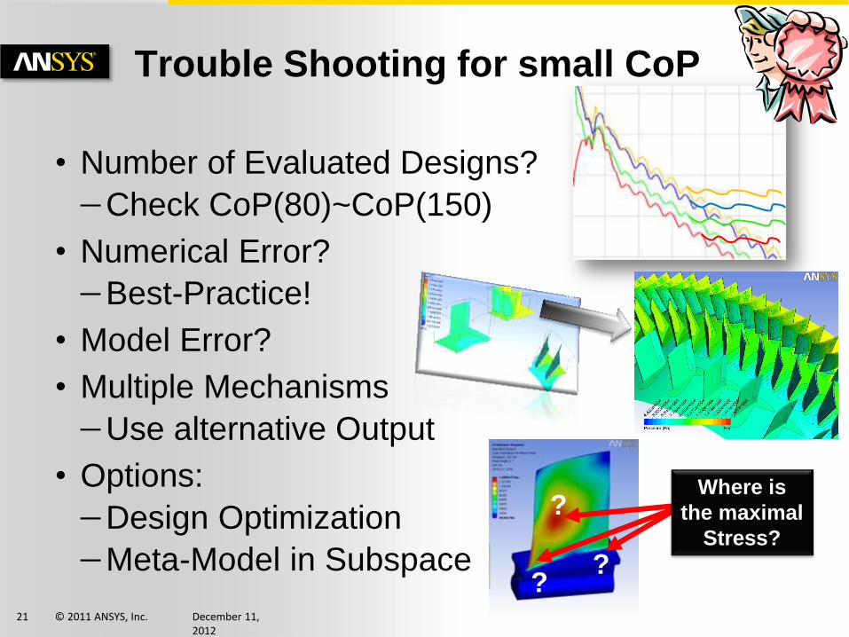
• Number of Evaluated Designs?
Check CoP(80)~CoP(150)
• Numerical Error?
Best-Practice!
• Model Error?
• Multiple Mechanisms
Use alternative Output
• Options:
Design Optimization
Meta-Model in Subspace
Trouble Shooting for small CoP
Where is
the maximal
Stress?
?
? ?
© 2011 ANSYS, Inc. December 11, 2012
22
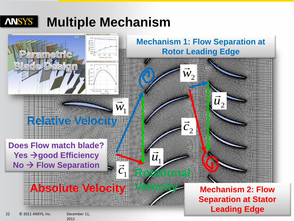
Multiple Mechanism
1u
1c
1w
Absolute Velocity
Relative Velocity
Rotational
Velocity
2u
2c
2w
Mechanism 1: Flow Separation at
Rotor Leading Edge
Mechanism 2: Flow
Separation at Stator
Leading Edge
Does Flow match blade?
Yes good Efficiency
No Flow Separation
© 2011 ANSYS, Inc. December 11, 2012
23
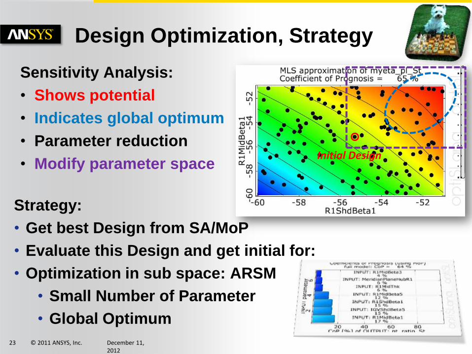
Design Optimization, Strategy
Sensitivity Analysis:
• Shows potential
• Indicates global optimum
• Parameter reduction
• Modify parameter space
Strategy:
• Get best Design from SA/MoP
• Evaluate this Design and get initial for:
• Optimization in sub space: ARSM
• Small Number of Parameter
• Global Optimum
Initial Design

© 2011 ANSYS, Inc. December 11, 2012
24
Design Optimization, Summary
Initial Design
Best Design SA
Best Design Solved (MoP)
Best Design ARSM
Efficiency [%] 87.0 88.0 88.9 (91.0) 88.9
ptot Ratio [-] 1.41 1.41 1.41 (1.44) 1.41
Max. Stress [MPa] 219 235 232 (230) 239
#Designs 1 150 1 (0) 100