multi-pose interactive linkage design€¦ · g. nishida & a. bousseau & d. g. aliaga /...
TRANSCRIPT

EUROGRAPHICS 2019 / P. Alliez and F. Pellacini(Guest Editors)
Volume 38 (2019), Number 2
Multi-Pose Interactive Linkage Design
Gen Nishida1 , Adrien Bousseau2 , Daniel G. Aliaga1
1Purdue University, USA2Inria, France
Teaser
a) b)
c) d)
e) f)
Fixed bodies Moving bodies
Figure 1: Interactive design of a multi-pose and multi-body linkage. Our system relies on a simple 2D drawing interface to let the userdesign a multi-body object including (a) fixed bodies, (b) moving bodies (green and purple shapes), (c) multiple poses for each moving bodyto specify the desired motion, and (d) a desired region for the linkage mechanism. Then, our system automatically generates a 2.5D linkagemechanism that makes the moving bodies traverse all input poses in a desired order without any collision (e). The system also automaticallygenerates linkage parts ready for 3D printing and assembly (f). Please refer to the accompanying video for a demonstration of the sketchinginterface and animations of the resulting mechanisms.
AbstractWe introduce an interactive tool for novice users to design mechanical objects made of 2.5D linkages. Users simply draw theshape of the object and a few key poses of its multiple moving parts. Our approach automatically generates a one-degree-of-freedom linkage that connects the fixed and moving parts, such that the moving parts traverse all input poses in order withoutany collision with the fixed and other moving parts. In addition, our approach avoids common linkage defects and favorscompact linkages and smooth motion trajectories. Finally, our system automatically generates the 3D geometry of the objectand its links, allowing the rapid creation of a physical mockup of the designed object.
CCS Concepts• Computing methodologies → Shape modeling;
1. Introduction
With the proliferation of rapid-prototyping technology, anyone cannow engage in the creation of personalized mechanical objects, farbeyond what is achievable with popular construction kits like LegoTechnic. Yet, designing a mechanical object that performs a desiredmotion raises multiple challenges for novices. First, small changesin the mechanism geometry can result in large changes in the result-ing motion, making design exploration a tedious, counter-intuitivetask. Second, many linkage setups for multi-pose and multi-bodyobjects encounter some forms of defects or collisions during theiranimation. We propose an interactive system that hides such chal-
lenges from the user, who can then focus on designing both theshape and the motion of an object composed of multiple movingbodies connected by automatically-computed linkages.
We created our system to provide several important features forinteractive design:
Shape and motion control. We need a user interface that allowsthe rapid specification of 3D shapes and their motion, even fornovices with limited knowledge in 3D modeling and animation. Weachieve this goal thanks to a simple sketch-based interface, whereusers draw the 2D profile of each moving part, as well as its position
c© 2019 The Author(s)Computer Graphics Forum c© 2019 The Eurographics Association and JohnWiley & Sons Ltd. Published by John Wiley & Sons Ltd.

G. Nishida & A. Bousseau & D. G. Aliaga / Multi-Pose Interactive Linkage Design
and orientation in a few key poses (Figure 1a-d). These 2D shapesare then extruded in depth to obtain a 2.5D multi-body object. Oursystem supports a varying number of poses, so that users can iter-atively refine complex trajectories by inserting new poses. In addi-tion, we also offer a global parameter to control the smoothness ofthe trajectories and balance it against the accuracy with which themoving bodies traverse the specified poses.
Mechanism size and location control. Given the sketched input,our approach automatically connects the moving and fixed bodieswith a generated linkage that makes the moving bodies traversetheir poses in the specified order without colliding with the fixedand other moving bodies (Figure 1e). We provide two user controlson this linkage synthesis. First, we allow users to indicate a regionwhere the linkage should be placed to satisfy aesthetic or usabilitygoals. Second, we offer a global parameter to control the size ofthe mechanism, which again competes with the smoothness andaccuracy of the resulting trajectories.
Rapid prototyping. Finally, we seek to allow rapid testing of thegenerated linkage in the physical world. We achieve this goal by de-signing parametric linkage geometry that is ready for 3D printingand assembly without additional fixtures. In addition, our systemalso avoids various common linkage defects to guarantee that ourresult is functional. Our current implementation supports multi-barlinkages (e.g., 4-bar, 6-bar, 8-bar linkages, etc.) as well as the pop-ular slider crank.
To satisfy the above requirements, we have created a novel multi-bar linkage method that includes an optimization with multiple con-current goals. Soft terms measure the accuracy of the moving bodytrajectory with respect to the specified poses, the smoothness ofthis trajectory, the compactness of the mechanism, and the locationof the mechanism within the user-specified region. Hard constraintsensure that the linkage is free of common defects, such as wrong or-dering of the traversed poses, alignment of consecutive links duringmotion, disconnected pose space, as well as any collision betweenthe moving and fixed bodies or between the links. Unfortunately,several of these hard constraints require running a kinematic simu-lation of the linkage with actual 3D geometry, and as such cannot beintegrated in standard gradient-based solvers. Instead, we adopt astochastic exploration of the solution space, where we first generatea large number of linkages that approximately satisfy the specifiedposes, then reject the ones that violate the hard constraints, and fi-nally select the valid linkage that best satisfies all soft terms. We ac-celerate this exploration using a coarse-to-fine refinement method-ology based on particle filter optimization [LCS16], thus providingusers with valid designs after only a few seconds of computation.
In summary, our contributions include:
• Interactive Design. An end-to-end approach to create physical2.5D objects made of multiple moving bodies connected by link-ages. Our system targets novice users and lets them design dy-namic objects simply by sketching both the shape and the poseof the moving parts. We offer fine control on the trajectory of themoving bodies by supporting multiple poses, and global con-trol on the trade-offs between compactness of the mechanism,smoothness of the trajectories, and accuracy with respect to theinput poses.
• Practical and Defect-Free Solution. A stochastic optimizationthat efficiently finds a well-behaved linkage that satisfies the usergoal while avoiding defects and collisions. While not real-time,this optimization is fast enough to let users iterate on a designwithin seconds.
• Automatic Synthesis. An automatic linkage synthesis procedurethat outputs geometry of the mechanism ready for fabricationand assembly.
2. Background and Related Work
The goal of our interactive approach is to help casual users createfabrication-ready 2.5D multi-body mechanical objects composedof planar linkages. We first provide a brief introduction to pla-nar linkages, and then discuss related work on linkage synthesisfrom the engineering literature and on interactive mechanical de-sign from the computer graphics literature.
Planar linkages. In our context, a linkage is a mechanism com-posed of rigid links, also called bars, connected by joints. Further-more, we focus on two types of one-degree-of-freedom joints – therotary hinge, also called revolute joint, and the linear slider, alsocalled prismatic joint. Linkage mechanisms are commonly classi-fied according to the number of links they are composed of and thetypes of their joints, which are denoted with the letter R for revoluteand P for prismatic. Our system supports multi-bar linkages with Kmoving bodies that are connected by revolute joints (Figure 3). Forexample, for K = 1 this mechanism is reduced to the 4R four-barlinkage, and for K = 2 it becomes the Watt-I type six-bar linkage,which appear in many everyday objects [HD64, SE84, MS11]. Oursystem also supports the RRRP linkage or slider crank, which is arotating link connected to a translating slider using three revolutejoints and one prismatic joint. We refer the interested reader to thebook by McCarthy and Soh [MS11] for additional details on differ-ent types of linkages. In what follows, we refer to the moving partsof an object as the moving bodies, which are connected to a fixedbody by the linkage.
Linkage synthesis. The seminal Burmester theory [Bur86] isa graphical method to solve for the parameters of a planar 4Rfour-bar linkage for up to five input poses of the moving body.Later work expressed the geometric constraints induced by thelengths of the links as a system of equations [SR67, San59]. How-ever, such methods disregard other desired properties of a link-age, such as respecting the order of visited poses (order defect)or avoiding singular configurations that occur when two adjacentbars are collinear (branch defect) or when different poses cannotbe reached without disassembly (circuit defect), as reviewed byBalli and Chand [BC02]. Multiple extensions to Burmester’s the-ory have been proposed to address some of these defects [Fil72,Wal76, CF91, CM93, MC95, PM14, PMW14]. Unfortunately, mostsolutions are specific to a particular type of defect and a partic-ular type of linkage. More importantly, these geometric methodsassume that the designer provides exact input poses, and producesolutions that respect these poses with high precision [CKE13]. Incontrast, we target a casual design scenario where the input posesare approximately specified by rapid sketching. Our system thusseeks to balance the precision of the pose traversal with other ob-
c© 2019 The Author(s)Computer Graphics Forum c© 2019 The Eurographics Association and John Wiley & Sons Ltd.

G. Nishida & A. Bousseau & D. G. Aliaga / Multi-Pose Interactive Linkage Design
jectives such as the smoothness of the trajectory and compactnessof the linkage.
Our need to satisfy multiple concurrent objectives makes ourwork most similar to optimization-based linkage synthesis meth-ods. Various optimization strategies have been considered, suchas evolutionary algorithms [BD09], simulated annealing [MA08],non-convex optimization [GLC∗16], and differential evolution[GM12,KN17]. However, many of these approaches target the pathgeneration problem, where the goal is to generate a linkage whoseend-effector follows a given trajectory. We target the different prob-lem of motion generation or body guidance [MS11], where the goalis to make a moving body traverse a given set of poses, each de-fined by a position and an orientation. In addition, most methodsignore the linkage defects mentioned above, as well as collisions.One exception is the work by Zheng et al. [ZSC16], who proposea collision detection algorithm for a fold-able scissor linkage sys-tem. However, their approximate solution is specific to collisionsbetween the thin bars of scissor linkages, while we need to de-tect collisions between a more general class of objects includingarbitrary rigid bodies and a wider family of linkages. We addressthese challenges with an interactive design system that uses a cus-tom stochastic optimization having soft energy terms to measurethe quality of a linkage and hard constraints to prevent any defector collision.
Interactive mechanical design. The computer graphics com-munity has proposed multiple interactive mechanical design sys-tems. Motivated by applications in character animation, manymethods take an articulated model as input and focus on reproduc-ing a pre-defined animation [ZXS∗12, TCG∗14, CLM∗13]. In con-trast, our body guidance approach lets users sketch disconnectedfixed and moving bodies and generates a linkage that connects themsuch that the moving bodies traverse a set of desired poses.
Our method is most related to the system by Megaro etal. [MTG∗14], which allows users to create linkages by specify-ing the two extreme poses of a set of moving bodies. While wetake inspiration from their design workflow, our goal to supportmultiple poses of 2.5D bodies requires a different solution address-ing new challenges. First, the method needs to consider a muchlarger set of candidate linkages to produce the complex trajecto-ries dictated by multiple poses, which can include abrupt changesof orientation or direction of the moving bodies. Second, Megaroet al. focus on planar objects, which allows them to resolve colli-sions by offsetting mechanical components in depth. In contrast, wetarget 2.5D objects with co-planar moving bodies, which requiresus to run kinematic simulations during optimization for collisionavoidance. Third, while the algorithm by Megaro et al. automat-ically generates a single solution, our approach incorporates softobjectives, such as the smoothness of the trajectory and the com-pactness of the mechanism, which provides users a larger designspace. In addition, these soft objectives act as regularization termsagainst the specified poses, which users only need to specify ap-proximately. Finally, while Megaro et al. describe how to preventalignment of consecutive links on part of their mechanisms, theiralgorithm to generate connectors between the moving bodies cansuffer from defects that our method avoids, as detailed in our eval-
Check branch and circuit defects and
collision3D geometryGeneration
generCheck branch and circuit defects and
collisionCandidate sampling
Checkinghard‐constraints
1) 2) 4)Check branch and circuit defects and
collision
Check branch and circuit defects and
collisionPFO based onsoft‐constraints
3)
Figure 2: System pipeline. Our approach starts with 1) a randomsampling of mechanisms based on Erigid(x). 2) For each candidate,the hard-constraints, Cde f ect(x) and Ccoll(x) , are checked. Candi-dates that do not satisfy the hard-constraints are discarded. 3) Aparticle filter optimization is performed based on soft-constraints,Eacc(x), Esmooth(x), Eloc(x), and Esize(x). 4) Finally, the best can-didate is selected, and its fabrication-ready 3D geometry is gener-ated.
uation. Our method also needs to account for order defect, whichdoes not occur with only two poses.
Our work also relates to the system by Coros et al. [CTN∗13],where users sketch the motion curves of various actuation points onan articulated character provided as input. Their work is an instanceof the path generation problem. While the position and orientationof a moving body could in theory be specified by two point trajec-tories, path generation methods do not generalize to the problem ofbody guidance because these two trajectories should be perfectlysynchronized to maintain the rigidity and orientation of the movingbody – this is almost impossible to do manually.
While our goal is to generate a linkage from scratch, severalmethods have been proposed to modify existing linkages. In partic-ular, Bächer et al. [BCT15] allows users to edit a working linkagewhile preserving its functionality, while Megaro et al. [MZB∗17]convert rigid linkages into compliant mechanisms made of softflexures.
Finally, most of the above methods focus on the design of artic-ulated characters, while we target the design of everyday objectscomposed of multiple moving parts. We thus share the goal of Kooet al. [KLY∗14], who propose a modeling system to help designerscreate functional prototypes of mechanical objects. However, oursystem supports more complex motions thanks to multi-bar link-ages. In addition, the system by Koo et al. can generate mechanismsthat have more than one degree of freedom, which requires the userto move multiple links synchronously to achieve a target motion.In contrast, our approach produces mechanisms that have only onedegree of freedom, so it is easy for users to animate the fabricatedobject while maintaining the desired orientation.
3. Overview
The input to our method is a set of vector drawings representingfixed and moving parts of a rigid object, in several desired poses.Please refer to our accompanying video for several example designsessions using our sketching interface. Given this input, our goal isto generate rigid, one-degree-of-freedom mechanisms that enablethe moving bodies to traverse all poses in a desired order. Out ofthe many solutions that can perform this task, we favor the onesthat are compact and that yield a smooth trajectory. We expressthese design goals with four soft constraints represented as energy
c© 2019 The Author(s)Computer Graphics Forum c© 2019 The Eurographics Association and John Wiley & Sons Ltd.

G. Nishida & A. Bousseau & D. G. Aliaga / Multi-Pose Interactive Linkage Design
Fixed body
Figure 3: Multi-bar linkage. Our mechanisms consist of a fixedbody and K moving bodies connected by a linkage assembly thathas a single degree of freedom. Gray triangles represent rigidternary links, each of which has three revolute joints. The mech-anism consists of K four-bar loops, qk−1, rk−1, qk, and pk, wherethe index k varies from 1 to K for pk, from 0 to K for qk, and from 0to K−1 for rk. For K = 1, the mechanism reduces to a 4R four-barlinkage, and for K = 2, the mechanism becomes a Watt-I six-barlinkage [MS11].
terms: i) the accuracy of the trajectory with regard to the input posesEacc, ii) the smoothness of the trajectory Esmooth, iii) the distance ofthe mechanisms from a user-specified region at the first pose Eloc,and iv) the size of the mechanism Esize. In addition, we define twohard constraints: i) Ccoll – a valid mechanism should not produceany collision between the rigid bodies, nor between the links andjoints, and linkage should also not collide with any safety regionthat users optionally indicate, and ii) Cde f ect – the linkage shouldnot have any defect. Combining these terms gives the followingconstrained optimization
argminx
waccEacc(x)+wsmoothEsmooth(x)
+wlocEloc(x)+wsizeEsize(x)
subject to
{Ccoll(x)Cde f ect(x)
,
(1)
where x denotes the set of parameters of the linkage mechanism(see Section 4.2 for more details).
However, the soft and hard constraints of Equation 1 are highlynonlinear and also include terms that require a kinematic simula-tion to be evaluated (i.e., for Esmooth(x) and Ccoll(x)). We tacklethis challenge by decomposing the problem into multiple steps, asillustrated in Figure 2. First, we generate many candidate solutionsby mildly perturbing the poses of the sketched bodies and for eachcomputing a multi-bar linkage that passes through the perturbedposes (Section 4.1). This allows the system to consider solutionsthat might increase Eacc but decrease the other soft constraints. In asecond step, the candidates are checked against the hard constraints(Section 5). Our approach considers order, branch, and circuit de-fects as well as collisions. In a third step, a particle filter optimiza-tion is used to refine candidates, and the overall best solution interms of the soft constraints is selected (Section 6). Finally, wegenerate 3D models of the linkage as well as the fixed and mov-ing bodies that are ready to fabricate (Section 7).
4. Candidate Sampling
The first step of our method is to generate a large number of candi-date rigid mechanisms that approximately satisfy the input poses.Figure 3 illustrates our general multi-bar mechanism, where eachmoving body is attached to a fixed-length link, and is connectedto adjacent bodies by links and revolute joints that form four-barloops. For example, the left most four bars, q0, p1, q1, and r0,form a four-bar loop where the first moving body is attached tothe link p1 r1. Similarly, the k-th moving body is attached to thek-th four-bar loop, qk−1, rk−1, qk, and pk, and so forth. For K mov-ing bodies, our linkage mechanism has 3K + 1 joints that consistof pk(k = 1, · · · ,K), qk(k = 0, · · · ,K), and rk(k = 0, · · · ,K − 1).Since the linkage mechanism can be uniquely defined by the initialxy coordinates of the joints, there are 6K+2 variables to determine.
Megaro et al. [MTG∗14] proposed to generate linkages by sam-pling random joints along the boundary of the rigid bodies and byselecting pairs of links between adjacent bodies such that the linkshave minimal length variation between poses (two in their case).However, we found that this strategy often results in linkages thatperform poorly with regards to our soft and hard constraints (seeSection 8.6 for a comparison to Megaro et al. [MTG∗14]). We nextdescribe a more general sampling strategy that accounts for mul-tiple, approximate poses, and that considers joints away from theboundary of the rigid bodies.
4.1. Sampling
Our sampling approach is to augment the solution space by perturb-ing the input poses, such that candidate solutions admit deviationfrom the input poses, which can be balanced later against the othersoft and hard constraints. Since the first and last poses are typicallymore important than the intermediate poses, we only perturb the in-termediate poses by adding a Gaussian noise with an empirically-determined standard deviation σ = 0.5d, where d is the shortestlength of the bounding box of each moving body. We analyze theimpact of different values of σ in Section 8.4, but use σ = 0.5dfor all results in this paper. We also make sure that the perturbedmoving bodies do not collide with other moving and fixed bodies.Figure 4 illustrates our sampling process for K = 1 moving bodies(i.e., a four-bar linkage).
4.2. Multi-bar linkage
For each perturbation, our method seeks to generate a rigid multi-bar linkage system that best traverses the N perturbed poses of theK moving bodies T i′
k (i = 1, · · · ,N,k = 1, · · · ,K), which are repre-sented by their transformation matrices relative to the fixed body:
T i′k =
cosθi′k −sinθ
i′k ui′
ksinθ
i′k cosθ
i′k vi′
k0 0 1
. (2)
We initialize the solution by randomly sampling all the jointsat the first pose, p1
1···K ,q10···K ,r
10···K−1. The coordinates of the
joints at other poses are calculated as pik = T i′
k (T 1′k )−1 p1
k , qik =
T i′k (T 1′
k )−1q1k , and ri
k = T i′k (T 1′
k )−1r1k , respectively. Since the ma-
trices T i′k express transformations relative to the fixed body, the
c© 2019 The Author(s)Computer Graphics Forum c© 2019 The Eurographics Association and John Wiley & Sons Ltd.

G. Nishida & A. Bousseau & D. G. Aliaga / Multi-Pose Interactive Linkage Design
𝑞
1) 2) 3)
Fixed body Fixed body Fixed body
𝑅 𝑅 𝑅𝑇 ′
𝑝
𝑇 ′
𝑇
𝑞 𝑞𝑇 ′
4)
Fixed body
𝑅
Sampling for four‐bar linkage
����
����
��
��𝑞
𝑝
𝑝
𝑝𝑝
𝑞
Figure 4: Illustration of our sampling mechanism with K = 1moving bodies. 1) The intermediate N−2 poses (dotted rectangles)are perturbed to T i′
1 , and the position of the moving joint at the firstpose, p1
1, and its corresponding fixed point q0 are sampled within auser-specified desired region R (blue region). 2) The positions of themoving point at other poses are calculated as pi
1 = T i′1 (T 1′
1 )−1 p11.
3) The moving point p11 and the fixed point q0 are optimized to p1
1and q0 by minimizing the deviation of the link length between themoving point and the fixed point. The resulting link q0 p1
1 constitutesa driving link of the four-bar linkage at the first pose. 4) Anothermoving point at the first pose q1
1 and its corresponding fixed pointr0 are sampled in a similar manner for a follower. These two linksform a four-bar linkage.
transformation matrix for the fixed body T i′0 is the identity matrix.
However, the length of the links obtained with this random sam-pling is not necessarily constant across different poses. Therefore,we optimize the initial joints p1
k , q1k , and r1
k by minimizing
Erigid(p11···K ,q
10···K ,r
10···K−1) =
N
∑i=2
[∆l(pi
1,qi0)+∆l(qi
1,ri0)
+K
∑k=2
(∆l(pi
k,rik−2)+∆l(pi
k,qik−1)+∆l(qi
k,rik−1)
)], (3)
where ∆l(mi,ni) denote the deviation of length of link mn at the ith
pose
∆l(mi,ni) =(‖mi−ni‖2−‖m1−n1‖2)2
. (4)
The number of terms in Equation 3 is 2(N − 1) + 3(N − 1)(K−1), whereas there are 6K + 2 variables. For K = 1 (i.e., four-barlinkage), there are exact solutions that yield zero error for up to fiveposes, but for more than five poses in general position, there is nosolution that yields zero error [SR83, MS11]. For K > 1, there isno exact solution for more than 3 poses. Hence, our overarchingapproach is to minimize Equation 3 to get the best solutions, andrely on the soft energy term Eacc to penalize linkages that yield ahigh residual (Section 6). Since Equation 3 is twice differentiable,we can use any Newton or quasi-Newton method such as BFGSto minimize it. Note that while we sample the initial joints p1
k , q1k ,
and r1k inside the user-provided linkage region, the resultant joints
p1k , q1
k , and r1k can end up outside this region after optimization.
Nonetheless, the soft energy term Eloc (Section 6) will penalizesuch a solution proportionately. Note also that when a joint liesoutside its rigid body, we add a connector between them duringfabrication (Section 7.1).
The optimized joints p1k , q1
k , and r1k give us a multi-bar linkage
mechanism, and we can proceed with the detection of order, branch,and circuit defects as well as collisions.
Four‐bar linkage & slider crank
a) b)
𝜙
𝜙𝑝
𝑞
𝑟
𝑟 𝑝
𝑞
Moving body 𝑘
𝑟
𝜙
𝜙
𝜙
𝜙Fixed body
𝐿
𝜙𝑞
𝑝
𝑞
𝑟
Figure 5: Linkage mechanism. a) Four-bar loop in a multi-barlinkage. b) Slider crank.Defects
a) Order defect
Pose 1 Pose 2 Pose 3 Pose 4
b) Circuit defect c) Branch defect
Figure 6: Mechanism defects. a) The linkage goes from the secondpose to the last pose skipping the third pose. b) The linkage cannotgo from the left to the right without disassembly. c) The linkagecould go from the configuration in the middle to either the left orthe right when rotating the driving link (red arrow).
4.3. RRRP slider crank
For K = 1, we also support the RRRP slider crank, which is an-other popular mechanism encountered in many every day objects.The RRRP linkage consists of a driving link and a slider. We pa-rameterize the unit vector for the direction of the slider guide as~r(Figure 5b), and the rigidity objective function becomes
Erigid(p11,q
10,q
11,~r0) =
N
∑i=2
∆l(pi1,q
i0)+
((qi
1−q11)×~r0
)2. (5)
The last step is to locate the two end points of the slider guide. Wefind these points by running a kinematic simulation of the linkage,which gives us the two extreme positions of the prismatic joint.
5. Hard Constraints
We check the candidate mechanisms against a set of hard con-straints in order to reject candidates with linkage defects, poortransmission angles, or collisions. Please refer to Figure 5 for nota-tions.
5.1. Order defect
When the mechanism traverses the poses in a different order thanthe input, the mechanism is said to have order defect (Figure 6a)[BC02]. Chase and Fang [CF91] address this problem for four-barloops by analyzing the angle of the driving link in all poses (φ1 in
c© 2019 The Author(s)Computer Graphics Forum c© 2019 The Eurographics Association and John Wiley & Sons Ltd.

G. Nishida & A. Bousseau & D. G. Aliaga / Multi-Pose Interactive Linkage Design
Figure 5). We avoid this defect by ensuring all angles increase ordecrease monotonically from the first pose to the last pose.
5.2. Circuit defect
A circuit defect arises when the mechanism cannot be moved be-tween all input poses without disassembly (Figure 6b). For both4R four-bar and slider-crank linkages, circuit defects can only oc-cur for mechanisms where the shortest link can rotate fully withrespect to a neighboring link – the so-called Grashof condition. Insuch cases, the circuit defect is avoided if each of the two angles ofthe link opposite to the shortest doesn’t change sign across all inputposes. We extend this criteria to the multi-bar linkage by evaluatingthe condition for each four-bar loop, qk−1rk−1qk pk. In the exam-ple of Figure 5a, the shortest link is qk−1rk−1, so the signs of φ3and φ4 have to remain fixed. For linkages that satisfy the Grashofcondition, these two angles have always the same sign, so we onlyneed to check either one for detecting the circuit defect. Similarly,the sign of φ3 has to remain fixed for the slider-crank in Figure 5b.
For each four-bar loop, the Grashof condition occurs when thefollowing condition is satisfied:
|ls|+ |ll | ≤ |la|+ |lb|, (6)
where |l| denotes the length of link l, and ls, ll , la, and lb denotethe shortest, longest, and other two links, respectively [MS11]. Thecorresponding condition for the slider crank is
|ls|+L≤ |ll |, (7)
where L is the distance between the fixed joint and the slider guide(Figure 5b).
5.3. Branch defect
A branch defect occurs when the mechanism goes through aso-called stationary configuration, where two adjacent links arealigned (Figure 6c). In such cases, the links can follow any oftwo directions as the driving link rotates, which causes driveabil-ity problems [BC02].
This defect can only occur when the link qk−1rk−1 cannot rotatefully. In such cases, the branch defect can be detected by checkingthe sign of the transmission angle, which is angle φ3 in Figure 5.If the sign of this angle changes across the input poses, the mecha-nism has a branch defect.
To rotate fully, each four-bar loop has to satisfy the Grashof con-dition as well as the following condition [MS11]:
‖rk−1−qk−1‖+‖pk−qk−1‖< ‖qk− pk‖+‖qk− rk−1‖. (8)
For the slider crank, the corresponding condition is
‖p1−q0‖< ‖q1− p1‖−L. (9)
5.4. Poor transmission angle
When the transmission angle (φ3 in Figure 5) is close to zero, thedriving force and the torque that is transmitted to the followinglinks vanishes, which hinders the rotation of the following links. Toavoid this defect, we run a kinematic simulation and check whether
the transmission angle is too close to zero during the motion. Weused 10 degrees as the minimum threshold for the transmission an-gle. Note that when the transmission angle is zero, the branch defectoccurs as well.
Thomaszewski et al. [TCG∗14] avoid poor transmission angleusing a soft energy term that measures the area of the triangleformed by the two adjacent links rk−1qk and qk pk in Figure 5. Sincethey take an animated articulated model as input, they can evaluatethis energy term for all configurations of a motion cycle. In con-trast, while we considered adding a similar penalty to Equation 3during the linkage sampling step, we found that measuring this areaonly at the input poses is not sufficient to avoid poor transmissionangle during the entire animation.
5.5. Collision
Finally, we run a kinematic simulation from the first pose to thelast one and perform discrete collision detection between the rigidbodies. We also check for collisions between the linkage and theoptional user-specified safety regions. However, we do not need tocheck for collisions between the linkage and rigid bodies becausewe position the links at a different depth than the bodies (Figure 7).We also ensure that the links and joints do not collide when wegenerate their respective geometries, as detailed in Section 7.
Since detecting collisions requires running a kinematic simula-tion, which is significantly more expensive than detecting the afore-mentioned defects, we only test collision for the candidates that aredefect free.
6. Soft Constraints
Next, we locally perturb the remaining candidates so as to refine thesolution, checking for each perturbation that it does not violate thehard constraints. We define a cost function to evaluate a given link-age x with four soft constraints, and use this cost to guide a particlefilter formulation of a stochastic global optimization [LCS16].
The soft constraints are accuracy of the traversed poses, Eacc(x),smoothness of the trajectory, Esmooth(x), distance of joints from thedesired linkage region, Eloc(x), and size of the linkage, Esize(x).The first soft constraint, accuracy of the traversed poses, is definedby
Eacc(x) =1
N|JM |
N
∑i=1
∑j∈JM
∥∥∥ ji− ji∥∥∥2
, (10)
where JM denotes the set of all moving joints, |JM | denotes thenumber of moving joints, ji denotes the input coordinates of themoving joint j at pose i, and ji denotes the actual coordinates ofthe joint j at pose i. The accuracy, Eacc(x), will be 0 if the linkagetraverses all the input poses exactly.
The second soft constraint, smoothness of the trajectory, is ap-proximated by the tortuosity of the trajectory between poses as fol-lows:
Esmooth(x) =1
(N−1)|JM |
N−1
∑i=1
∑j∈JM
∫ pose i+1pose i s j(t)dt∥∥ ji+1− ji
∥∥ , (11)
c© 2019 The Author(s)Computer Graphics Forum c© 2019 The Eurographics Association and John Wiley & Sons Ltd.

G. Nishida & A. Bousseau & D. G. Aliaga / Multi-Pose Interactive Linkage Design
where s j(t) denotes the speed of joint j at time t during the simula-tion. The summands are the ratio between the length of the motioncurve between two consecutive input poses and the distance be-tween its endpoints. This term helps the generated linkage avoid azigzag trajectory.
The third soft constraint, location of the linkage, is evaluatedas the average distance of joints at the first pose from the user-specified linkage region R,
Eloc(x) =1|J | ∑
j∈Jdist( j1,R) , (12)
where J denotes the set of all joints, |J | denotes the number ofjoints, and dist( j1,R) denotes the distance of joint j at the firstpose from region R.
Finally, the fourth soft constraint, size of the linkage, is measuredby
Esize(x) =1|L| ∑
l∈L|l| , (13)
where L denotes the set of all links, |L| denotes the number oflinks, and |l| denotes the length of link l.
Altogether, the user specifies weights to balance these four termsinto a single cost function:
Cost(x) = waccEacc(x)+wsmoothEsmooth(x)+wlocEloc(x)+wsizeEsize(x) . (14)
We use wacc = 1, wsmooth = 1, wloc = 10, and wsize = 1 for all theresults except Figure 11 in the paper.
Using the cost function, our approach performs the particle filteroptimization. It starts with the linkages that satisfied the hard con-straints, X0 = {x0}. At each iteration, the optimization perturbs thejoints of each linkage x to get a new linkage x′. The method uses aGaussian distribution with a standard deviation of 0.5d, where d isthe shortest length of the bounding box of the moving body as theproposal distribution. Then, it re-checks the hard constraints in Sec-tion 5 on the perturbed linkages x′. If a new perturbed linkage nolonger satisfies all the hard-constraints, its weight is set to 0 whichwill cause it to be subsequently ignored. Otherwise, its weight iscalculated by
weight(x) = exp[− λ ·Cost(x)
maxx0∈X0 Cost(x0)
], (15)
where λ is the exponential decay constant. A low value of λ tendsto increase the randomness of its resampling, whereas a high valueof λ facilitates convergence. However, too high value of λ resultsin underflow of Equation 15, so we divide it by the maximum costof the initial linkages. We use λ = 20 for all our results. Amongthe linkages of the previous iteration and newly added linkages, weresample 100 linkages using their weights as probabilities. Thus,even if all the new perturbed linkages have a weight of 0 due to nolonger satisfying the hard-constraints, a new set of linkages can stillbe resampled from the previous set. After convergence, we selectthe lowest cost linkage as the final solution.
Fixed body
Moving bo
dy Side view
Attachment pointFixed joint
Joint connector
Moving joint
Body
Link
Link
Figure 7: Connecting the linkage to the rigid bodies. The jointsof the generated linkage are automatically attached to the closestpoints on the rigid bodies using joint connectors.
7. Fabrication-Ready Geometry
Given a linkage that satisfies all our previous constraints, we gener-ate a fabrication-ready 2.5D object and assembly of links where thelinks are distributed at discrete depths around the fixed and movingbodies. This process involves three main steps. First, we connecteach joint to its associated fixed or moving body. Second, we iden-tify potential collisions within the linkage, from which we deduceconstraints on the relative depth of the links and connectors. Wesolve for a depth ordering that satisfies these constraints to obtain alinkage free of collision during motion. Finally, we describe a para-metric model that produces the linkage geometry given the depth ofeach link.
7.1. Connecting links to bodies
Our sampling procedure generates joints on and around the inputrigid bodies (Section 4.1). We attach each such floating joint to theclosest point of its body using a joint connector, which we positionat an ε-distance from the boundary of the rigid body to increaserobustness (Figure 7). In contrast to links, joint connectors are fixedto the rigid bodies. We fixed the dimensions of the joint connectorsand links to offer a good trade-off between size and strength. Notethat the joint connectors lie on the sides of the bodies to preventcollision between the links and the bodies (Figure 7, side view).
7.2. Depth-ordering
Once we have the links and joint connectors in place, we run a 2Dkinematic simulation to find if they collide during the motion of themechanism. We distinguish two collision scenarios: 1. when a linkcollides with the attachment point of a joint connector (Figure 8a),and 2. when a link collides with a joint (Figure 8b). These twoscenarios also apply to joint connectors.
To avoid the first type of collision, the joint connector and itsattachment point need to be closer to the body than the movinglink. Denoting z(c) the depth of the joint connector with respectto the body, and z(l) the depth of the moving link, we obtain theordering inequality
z(c)< z(l). (16)
To avoid the second type of collision, the moving link needs to bein front or behind all the links and joint connectors connected to the
c© 2019 The Author(s)Computer Graphics Forum c© 2019 The Eurographics Association and John Wiley & Sons Ltd.

G. Nishida & A. Bousseau & D. G. Aliaga / Multi-Pose Interactive Linkage Design
Body
a) b)
Body
Link Collision
Figure 8: Two cases of collision between links. During the kine-matic simulation, two types of collisions in 2D projected space arerecorded: a) link la collides with pb, the attachment point of jointconnector lb. b) link la collides with joint jb.
colliding joint. Denoting L j this set of links and joint connectors,we obtain the disjunctive ordering inequality
z(l)< minl j∈L j
z(l j)∨
z(l)> maxl j∈L j
z(l j). (17)
In addition to these two constraints, we also need to prevent ad-jacent links or joint connectors to be at the same depth due to ourlinkage geometry design (Figure 9). Denoting la and lb two links orconnectors sharing a joint, we express this constraint as
z(la) 6= z(lb), (18)
which can be seen as a disjunctive inequality
z(la)< z(lb)∨
z(la)> z(lb). (19)
The same constraint also applies when two links la and lb inter-sect in the first pose.
Finally, we solve for a depth ordering of the links and joint con-nectors that satisfies all the constraints listed above. Since sev-eral solutions may exist, we favor the one that occupies the leastspace, i.e. with the smallest depth complexity maxl∈L z(l). Coroset al. [CTN∗13] tackle a similar ordering problem, which they solvewith an off-the-shelf Constraint Satisfaction Problem (CSP) solver.We follow their approach using Gecode [Gec18], which finds a so-lution in a few milliseconds for our problem. However, some can-didate mechanisms may not admit any solution, in which case wereject those candidates.
7.3. 3D geometry
Given a valid depth ordering of links and joint connectors, our sys-tem automatically generates the geometry of the mechanism basedon a parametric linkage model. Figure 9a illustrates the parame-ters of this model on one side of an object, the opposite side beingobtained by symmetry. We define the distance between two com-ponents of depth order z(la) and z(lb) as
height(z(la)− z(lb)
)=(z(la)− z(lb)
)(LD+ JD+2GP
)−LD ,
(20)where LD is the height of a link, JD is the height of a joint cap, andGP is the gap size between components of adjacent depth orders.The distance between a joint connector and the body is calculated in
1
Fixed body ( 0)
Link
b) Top view of binary link
d) Top view of slider guide
a) Side view of 3D geometry
Moving joint
Fixed body ( 0)
Joint connector ( 1)
Joint connector ( 4)
Link ( 3)
42
1
Moving body ( 0)
Moving body ( 0)
Fixed joint
e) More complex linkage
c) Top view of ternary link
Figure 9: Parameterized linkage geometry. a) The height of thejoints is computed from the depth of the link, z. b) Top view of abinary link. c) Top view of a ternary link. d) Top view of a sliderguide. e) In the case where three links are connected via a joint,the joint should be attached to the link that is located in the middle,and other links have a hole at the corresponding position.
a similar manner. We adjusted the values of LD, JD and GP basedon the scale and precision of our 3D printer.
In the case where three links are connected via a joint, the jointis attached to the link that is located in the middle, and other linkshave a hole at the corresponding position (Figure 9). The height ofthe joint can be determined by Equation 20.
8. Results
We implemented our approach on an i7-based PC workstation with12 GB of memory and NVidia GTX980 graphics card. Our toolwas implemented in C++ using OpenGL/GLSL. For minimizingEquations 3 and 5, we use the BFGS algorithm implemented indlib C++ library [Kin09]. For the kinematic simulation, we imple-mented our custom simulator following the symbolic reconstruc-tion approach [BBJP12]. We found that symbolic reconstruction isfaster than solving the so-called position loop equations, which in-volve a lot of trigonometric calculations [MS11].
8.1. Generated mechanical objects
Figure 10 shows multiple mechanical objects created using oursketching tool. Most of the examples require a complex motion.
c© 2019 The Author(s)Computer Graphics Forum c© 2019 The Eurographics Association and John Wiley & Sons Ltd.
G. Nishida & A. Bousseau & D. G. Aliaga / Multi-Pose Interactive Linkage Design
For instance, the car roof, sofa bed, and folding table need a par-ticular trajectory to avoid collisions. Figure 1 shows a retractablecar roof, for which the user specified three key poses of the tworoof parts. Also, the power shovel, bulldozer, and garbage truckexamples in Figure 10 use three poses to control the orientation ofthe moving body during the motion. For instance, the garbage truckkeeps its waste container upright until right before it reaches the topof the truck. Please refer to the accompanying video for animationsof these mechanisms.
Our approach allows the user to interactively obtain different so-lutions by changing the weights for the soft-terms, the accuracy,smoothness, and size of the linkage (Figure 11). Since the inputposes might not be accurate, the user can balance the accuracy andother soft-terms to obtain more desired linkage.
8.2. 3D printing
The output of our approach is a 3D geometry that consists of themain rigid bodies that the user sketched and links that are generatedby our system. Figure 12 shows the printed parts of the wall bed,wall chair, sofa bed, garbage truck, and folding table. The physicalobjects can be assembled without any additional bolts and screws.It took less than a minute to assemble the fabricated parts for eachresult in the paper. Please refer to the accompanying video for theactual assembly of some of the printed objects.
8.3. Performance
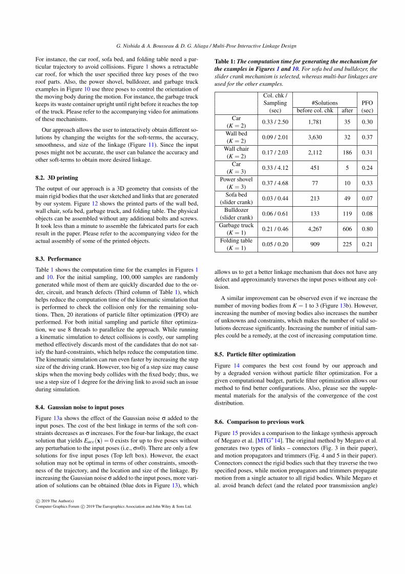
Table 1 shows the computation time for the examples in Figures 1and 10. For the initial sampling, 100,000 samples are randomlygenerated while most of them are quickly discarded due to the or-der, circuit, and branch defects (Third column of Table 1), whichhelps reduce the computation time of the kinematic simulation thatis performed to check the collision only for the remaining solu-tions. Then, 20 iterations of particle filter optimization (PFO) areperformed. For both initial sampling and particle filter optimiza-tion, we use 8 threads to parallelize the approach. While runninga kinematic simulation to detect collisions is costly, our samplingmethod effectively discards most of the candidates that do not sat-isfy the hard-constraints, which helps reduce the computation time.The kinematic simulation can run even faster by increasing the stepsize of the driving crank. However, too big of a step size may causeskips when the moving body collides with the fixed body; thus, weuse a step size of 1 degree for the driving link to avoid such an issueduring simulation.
8.4. Gaussian noise to input poses
Figure 13a shows the effect of the Gaussian noise σ added to theinput poses. The cost of the best linkage in terms of the soft con-straints decreases as σ increases. For the four-bar linkage, the exactsolution that yields Eacc(x) = 0 exists for up to five poses withoutany perturbation to the input poses (i.e., σ=0). There are only a fewsolutions for five input poses (Top left box). However, the exactsolution may not be optimal in terms of other constraints, smooth-ness of the trajectory, and the location and size of the linkage. Byincreasing the Gaussian noise σ added to the input poses, more vari-ation of solutions can be obtained (blue dots in Figure 13), which
Table 1: The computation time for generating the mechanism forthe examples in Figures 1 and 10. For sofa bed and bulldozer, theslider crank mechanism is selected, whereas multi-bar linkages areused for the other examples.
Col. chk /Sampling #Solutions PFO
(sec) before col. chk after (sec)Car
(K = 2)0.33 / 2.50 1,781 35 0.30
Wall bed(K = 2)
0.09 / 2.01 3,630 32 0.37
Wall chair(K = 2)
0.17 / 2.03 2,112 186 0.31
Car(K = 3)
0.33 / 4.12 451 5 0.24
Power shovel(K = 3)
0.37 / 4.68 77 10 0.33
Sofa bed(slider crank)
0.03 / 0.44 213 49 0.07
Bulldozer(slider crank)
0.06 / 0.61 133 119 0.08
Garbage truck(K = 1)
0.21 / 0.46 4,267 606 0.80
Folding table(K = 1)
0.05 / 0.20 909 225 0.21
allows us to get a better linkage mechanism that does not have anydefect and approximately traverses the input poses without any col-lision.
A similar improvement can be observed even if we increase thenumber of moving bodies from K = 1 to 3 (Figure 13b). However,increasing the number of moving bodies also increases the numberof unknowns and constraints, which makes the number of valid so-lutions decrease significantly. Increasing the number of initial sam-ples could be a remedy, at the cost of increasing computation time.
8.5. Particle filter optimization
Figure 14 compares the best cost found by our approach andby a degraded version without particle filter optimization. For agiven computational budget, particle filter optimization allows ourmethod to find better configurations. Also, please see the supple-mental materials for the analysis of the convergence of the costdistribution.
8.6. Comparison to previous work
Figure 15 provides a comparison to the linkage synthesis approachof Megaro et al. [MTG∗14]. The original method by Megaro et al.generates two types of links – connectors (Fig. 3 in their paper),and motion propagators and trimmers (Fig. 4 and 5 in their paper).Connectors connect the rigid bodies such that they traverse the twospecified poses, while motion propagators and trimmers propagatemotion from a single actuator to all rigid bodies. While Megaro etal. avoid branch defect (and the related poor transmission angle)
c© 2019 The Author(s)Computer Graphics Forum c© 2019 The Eurographics Association and John Wiley & Sons Ltd.

G. Nishida & A. Bousseau & D. G. Aliaga / Multi-Pose Interactive Linkage Design
Results
Sofa bed Bulldozer Folding tableBed Power shovelCar roofChair Garbage truck
Figure 10: Generated dynamic objects. Each column shows a dynamic object created with our system. The top row shows the input sketchesincluding the poses and desired region for the initial location of the linkage. The middle and bottom rows show the generated 3D geometrythat consists of the designed bodies and generated linkage. The first two examples have two moving bodies, whereas the third and forth havethree moving bodies. The fifth and sixth columns use the slider crank mechanism, and the last two columns use a 4R four-bar linkage. Pleaserefer to the accompanying video for their actual motion.
b) c) a)
Figure Y. Alternative solutions. The user can interactively obtain different solutions by
changing the weights for the soft-terms. a) When only accuracy is taken into account, the
moving bodies traverse the input poses very accurately, but the linkage might become
unnecessarily large. b) More smooth trajectory can be achieved by sacrificing the accuracy
and size, while c) a smaller size of linkage can be achieved by sacrificing the accuracy and
smoothness.
Figure 11: Alternative solutions. The user can interactively obtaindifferent solutions by changing the weights for the soft-terms. a)When only accuracy is taken into account, the moving bodies tra-verse the input poses very accurately, but the linkage might becomeunnecessarily large. b) More smooth trajectory can be achieved bysacrificing the accuracy and size, while c) a smaller size of linkagecan be achieved by sacrificing the accuracy and smoothness.
for motion propagators and trimmers (Sec. 5 of their paper), theydo not prevent such defects when sampling their connectors (Sec.4.1 of their paper). Our comparison focuses on these connectorssince they are the ones defining the trajectory of the moving body,and may cause collisions (Figure 15a-b), undesired trajectory (Fig-ure 15c), and some defects (Figure 15d).
Figure 16a shows a complex object for which two extreme posesare not enough to achieve the desired trajectory. Unlike the methodby Megaro et al., our approach allows users to refine the trajectoryby adding intermediate poses (Figure 16b).
8.7. User study
We conducted a user study to evaluate the benefits of our auto-matic approach over manual linkage design. We recruited eight vol-
Table 2: Summary of the manual design task The average of Eaccis shown in terms of d, where d is the shortest length of the bound-ing box of the moving body.
Avg. designtime (min)
Give up (%) Avg. Eacc Our Eacc
Task 1 3.9 0 0.23d 0.0000075dTask 2 14.6 37.5 0.98d 0.00045d
untary graduate-school-age participants without any experience inlinkage design. After letting the users have time to play with oursystem, we asked each participant to perform two specific designtasks (Figure 17). In the first task, two poses of a moving body areprovided, and the subject is required to manually design a four-bar linkage that moves the moving body from the first pose to thesecond pose. In the second task, three poses are provided, and theshape of the fixed body adds more chance of collision for the mov-ing body, which makes the task more difficult. The participants canclaim that the task is completed if the moving body approximatelytraverses the input poses. Also, they can give up the task if they findit too difficult.
Table 2 summarizes the results of this user study, and Figure 17shows some of the designed linkages. Please refer to the supple-mental materials for all the designed linkages by the participants.While participants managed to design a reasonable linkage in a fewminutes for the simple task, three did not complete the second task,which took 15 minutes on average for the five remaining partici-pants. In addition, the resulting linkages do not traverse the inputposes precisely (Eacc in Table 2). In contrast, our system producescompact mechanisms that accurately capture the target motion forboth tasks.
c© 2019 The Author(s)Computer Graphics Forum c© 2019 The Eurographics Association and John Wiley & Sons Ltd.

G. Nishida & A. Bousseau & D. G. Aliaga / Multi-Pose Interactive Linkage Design
e)
c)
b)
a)
d)
Figure 12: 3D printed examples. The output 3D geometry of a)wall bed, b) wall chair, c) sofa bed, d) garbage truck, and e) foldingtable were printed with a desktop 3D printer. The printed parts canbe assembled readily without additional bolts and nuts.
9. Conclusions and Future Work
We proposed an interactive system to quickly design a mechanicalobject that produces a desired motion. Users only interact with thesystem by sketching disconnected fixed and moving bodies, whileall the burden of linkage design is handled by our automatic ap-proach. Guided by the long history of four-bar, six-bar and multi-bar linkage studies, we efficiently generate planar linkages thatavoid common defects. Collision is also taken into account by run-ning a kinematic simulation and by automatically ordering links indepth. As such, our system greatly accelerates prototyping of phys-ical, dynamic objects.
While our generalization of four-bar, six-bar, and eight-bar link-ages to multi-bar linkages can generate many everyday objects,there are still some complex designs that cannot be effectively rep-resented by our mechanism as illustrated in Figure 18. The expres-siveness of our system could be expanded by supporting other typesof linkages with various types of joints, such as gear, cam, andscrew. However, several ingredients of our approach are linkage-dependent. First, the rigidity energies Erigid (Equation 3 and 5) usedto generate candidate linkages are specific to our custom multi-barlinkages. Similarly, our parametric linkage model would need tobe extended to fabricate other types of joints. Additional hard con-
𝜎
Best cost
Pose 12
3
45
𝜎 0 𝜎 0.2𝑑 𝜎 0.5𝑑
1 moving body (𝜎 0) 2 moving bodies (𝜎 0) 3 moving bodies (𝜎 0)
3
Pose 1
2
Norm
alized
best cost
𝜎
a)
b)
#sol=10𝐾 #sol=1𝐾 #sol=0.1𝐾
Figure 13: Solution distribution analysis. a) By increasing theGaussian noise σ for the input poses, more variation of solutionscan be obtained, which increases the chance to find better solutionsin terms of our soft constraints. The top row shows the best linkageobtained for the perturbation noise σ = 0, 0.2d, and 0.5d, whered is the shortest length of the moving body, and the solution dis-tribution for the fixed joints (blue dots). Notice that there are onlya few solutions for five poses without any perturbation (i.e., σ=0).While the linkages for σ = 0.2d and 0.5d do not traverse the inputposes exactly, the size of the obtained linkage becomes smaller toachieve a lower cost. Please refer to the supplemental materials forthe solution distribution for 3 poses and 4 poses. b) Increasing thenumber of moving bodies adds more constraints, which reduces thevalid solutions. The number in each box shows the number of validsolutions. Adding the Gaussian noise still improves the obtainedlinkage in terms of the cost.
straints may also be needed to cover the defects of other linkages.Finally, more complex linkages have additional components, whichincreases the risk of collision between components, and the com-putation time for finding their valid depth ordering.
The thickness of the links and the size of the joints in our resultsare based on the precision of our desktop 3D printer, which resultsin big mechanisms for the small prototypes we fabricated. The rel-ative size of the mechanism with respect to the overall object wouldreduce if we used our approach to design bigger objects, or if weused more sturdy materials. However, our approach does not con-sider the driving force when finding the best mechanism. It would
c© 2019 The Author(s)Computer Graphics Forum c© 2019 The Eurographics Association and John Wiley & Sons Ltd.

G. Nishida & A. Bousseau & D. G. Aliaga / Multi-Pose Interactive Linkage Design
a) Sofa bed b) Folding table
Best cost
Best cost
Time [sec] Time [sec]
Figure 14: Effect of particle filter optimization. The blue pointsrepresent the best cost by our approach, whereas the red pointsrepresent the best cost obtained without particle filter optimization.For both, the points represent the mean values of 100 trials whilethe vertical bars show the 95% confidence interval.
c)
Stationary configuration
d)
Collision
a) b)
Collision
Non‐smooth motion
ChaCra [Megaro et al. 2014]
Figure 15: The results by [MTG∗14]. The linkage synthesis ap-proach of Megaro et al. [MTG∗14] does not consider any defect,collision, and the smoothness of the trajectory. As a result, the gen-erated connectors may cause a-b) collisions, c) undesired trajec-tory, and d) some defects.
be desired to minimize the driving force, especially when the sizeof the mechanism is scaled up. Supporting linkages for 3D motionis also an exciting direction of future work, although it raises nu-merous challenges for collision detection and linkage fabrication.
b)a)
Figure X. Motion controllability. Two poses may not be enough to control the motion. a) Only two poses result in an undesired intermediate pose for the dipper to dig. b) By adding an intermediate pose, the user can obtain more desired motion.
Figure 16: Motion controllability. Two poses may not be enoughto achieve a desired motion. a) Using only two poses, the dippershovel does not dig into the ground. b) Adding an intermediate poseallows the user to produce the proper motion.
User Study Xiaowei Andres Seunghoon
1)
2)
Pose 1Pose 2
Pose 1
Pose 2Pose 3
Example resultsTask Ours
Figure 17: User study. The subjects were asked to do two tasks, 1)easy and 2) difficult ones. While most of the subjects could success-fully find a valid solution that does not cause any collision from thefirst pose to the last pose, there is a significant error in the trajec-tory. Please see the accompanying video for the actual motion ofthe designed mechanism.Limitations
Pose 1
Pose 2
Pose 3
Figure 18: Limitations. Our approach cannot support all possibleposes, such as this example; as future work we could incorporatemore complex linkage types.
Acknowledgements
We would like to thank our user study participants for their timeand feedbacks, and the anonymous reviewers for their constructivesuggestions. This research was partially funded by the ERC start-ing grant D3 (ERC-2016-STG 714221), NSF CBET 1250232, IIS1302172, CHS 1816514, and by research and software donationsfrom Adobe.
References
[BBJP12] BÄCHER M., BICKEL B., JAMES D. L., PFISTER H.: Fabri-cating articulated characters from skinned meshes. ACM Trans. Graph.31, 4 (2012), 47:1–47:9. 8
[BC02] BALLI S., CHAND S.: Defects in link mechanisms and solutionrectification. Mechanism and Machine Theory 37, 9 (2002), 851 – 876.2, 5, 6
[BCT15] BÄCHER M., COROS S., THOMASZEWSKI B.: Linkedit: Inter-active linkage editing using symbolic kinematics. ACM Trans. Graph.34, 4 (2015), 99:1–99:8. 3
[BD09] BULATOVIC R. R., DORDEVIC S. R.: On the optimum synthesisof a four-bar linkage using differential evolution and method of variablecontrolled deviations. Mechanism and Machine Theory 44, 1 (2009), 235– 246. 3
[Bur86] BURMESTER L.: Lehrbuch der Kinematik. Verlag Von ArthurFelix, 1886. 2
c© 2019 The Author(s)Computer Graphics Forum c© 2019 The Eurographics Association and John Wiley & Sons Ltd.

G. Nishida & A. Bousseau & D. G. Aliaga / Multi-Pose Interactive Linkage Design
[CF91] CHASE T. R., FANG W. E.: Order rectification for complex num-ber based burmester curves. Journal of Mechanical Design - Transac-tions of the ASME 113, 3 (1991), 239–247. 2, 5
[CKE13] CHASE T. R., KINZEL G. L., ERDMAN A. G.: Computeraided mechanism synthesis: A historical perspective. Advances in Mech-anisms, Robotics and Design Education and Research (2013), 17–33. 2
[CLM∗13] CEYLAN D., LI W., MITRA N. J., AGRAWALA M., PAULYM.: Designing and fabricating mechanical automata from mocap se-quences. ACM Trans. Graph. 32, 6 (2013), 186:1–186:11. 3
[CM93] CHASE T. R., MIRTH J. A.: Circuits and branches of single-degree-of-freedom planar linkages. Journal of Mechanical Design -Transactions of the ASME 115, 2 (1993), 223–230. 2
[CTN∗13] COROS S., THOMASZEWSKI B., NORIS G., SUEDA S.,FORBERG M., SUMNER R. W., MATUSIK W., BICKEL B.: Computa-tional design of mechanical characters. ACM Trans. Graph. 32, 4 (2013),83:1–83:12. 3, 8
[Fil72] FILEMON E.: Useful ranges of centerpoint curves for design ofcrank-and-rocker linkages. Mechanism and Machine Theory 7, 1 (1972),47 – 53. 2
[Gec18] GECODE: Gecode: Generic constraint development environ-ment, 2018. Available from http://www.gecode.org. 8
[GLC∗16] GOULET V., LI W., CHEONG H., IORIO F., QUIMPER C.:Four-Bar Linkage Synthesis Using Non-convex Optimization. SpringerInternational Publishing, 2016, pp. 618–635. 3
[GM12] GOGATE G. R., MATEKAR S. B.: Optimum synthesis of motiongenerating four-bar mechanisms using alternate error functions. Mecha-nism and Machine Theory 54 (2012), 41 – 61. 3
[HD64] HARTENBERG R. S., DENAVIT J.: Kinematic Synthesis of Link-ages. McGraw-Hill, 1964. 2
[Kin09] KING D. E.: Dlib-ml: A machine learning toolkit. Journal ofMachine Learning Research 10 (2009), 1755–1758. 8
[KLY∗14] KOO B., LI W., YAO J., AGRAWALA M., MITRA N. J.: Cre-ating works-like prototypes of mechanical objects. ACM Trans. Graph.33, 6 (2014), 217:1–217:9. 3
[KN17] KAFASH S. H., NAHVI A.: Optimal synthesis of four-bar pathgenerator linkages using circular proximity function. Mechanism andMachine Theory 115 (2017), 18 – 34. 3
[LCS16] LIU B., CHENG S., SHI Y.: Particle filter optimization: A briefintroduction. In Advances in Swarm Intelligence (2016), Springer Inter-national Publishing, pp. 95–104. 2, 6
[MA08] MARTÍNEZ-ALFARO H.: Four-bar mechanism synthesis for ndesired path points using simulated annealing. Advances in Metaheuris-tics for Hard Optimization (2008), 23–37. 3
[MC95] MIRTH J. A., CHASE T. R.: Circuit rectification for four preci-sion position synthesis of four-bar and watt six-bar linkages. Journal ofMechanical Design 117, 4 (1995), 612–619. 2
[MS11] MCCARTHY J. M., SOH G. M.: Geometric Design of Linkages.Springer-Verlag, 2011. 2, 3, 4, 5, 6, 8
[MTG∗14] MEGARO V., THOMASZEWSKI B., GAUGE D., GRINSPUNE., COROS S., GROSS M.: Chacra: An interactive design sys-tem for rapid character crafting. In Proceedings of the ACM SIG-GRAPH/Eurographics Symposium on Computer Animation (2014), SCA’14, pp. 123–130. 3, 4, 9, 12
[MZB∗17] MEGARO V., ZEHNDER J., BÄCHER M., COROS S., GROSSM., THOMASZEWSKI B.: A computational design tool for compliantmechanisms. ACM Trans. Graph. 36, 4 (2017), 82:1–82:12. 3
[PM14] PLECNIK M. M., MCCARTHY J. M.: Numerical synthesis ofsix-bar linkages for mechanical computation. Journal of Mechanismsand Robotics 6, 3 (2014). 2
[PMW14] PLECNIK M., MCCARTHY J. M., WAMPLER C. W.: Kine-matic synthesis of a watt i six-bar linkage for body guidance. Advancesin Robot Kinematics (2014), 317–325. 2
[San59] SANDOR G. N.: A General Complex-number Method for PlaneKinematic Synthesis with Applications. Columbia University, 1959. 2
[SE84] SANDOR G. N., ERDMAN A. G.: Advanced Mechanism Design:Analysis and Synthesis. Prentice-Hall, Inc., 1984. 2
[SR67] SUH C. H., RADCLIFFE C. W.: Synthesis of plane linkages withuse of the displacement matrix. Journal of Engineering for Industry 89,2 (1967). 2
[SR83] SUH C., RADCLIFFE C. W.: Kinematics and Mechanisms De-sign. Krieger Pub Co, 1983. 5
[TCG∗14] THOMASZEWSKI B., COROS S., GAUGE D., MEGARO V.,GRINSPUN E., GROSS M.: Computational design of linkage-based char-acters. ACM Trans. Graph. 33, 4 (2014), 64:1–64:9. 3, 6
[Wal76] WALDRON K. J.: Elimination of the branch problem in graphi-cal burmester mechanism synthesis for four finitely separated positions.Journal of Engineering for Industry 98, 1 (1976), 176–182. 2
[ZSC16] ZHENG C., SUN T., CHEN X.: Deployable 3d link-ages with collision avoidance. In Proceedings of the ACM SIG-GRAPH/Eurographics Symposium on Computer Animation (2016), Eu-rographics Association, pp. 179–188. 3
[ZXS∗12] ZHU L., XU W., SNYDER J., LIU Y., WANG G., GUO B.:Motion-guided mechanical toy modeling. ACM Trans. Graph. 31, 6(2012), 127:1–127:10. 3
c© 2019 The Author(s)Computer Graphics Forum c© 2019 The Eurographics Association and John Wiley & Sons Ltd.