multi-sensor frequency domain multiple access interference canceller for ds-cdma systems
TRANSCRIPT

EUROPEAN TRANSACTIONS ON TELECOMMUNICATIONSEur. Trans. Telecomms. 2007; 18:263–273Published online 2 October 2006 in Wiley InterScience(www.interscience.wiley.com) DOI: 10.1002/ett.1146
Signal Processing
Multi-sensor frequency domain multiple access interferencecanceller for DS-CDMA systems
Luis Goncalves1,3∗ and Atılio Gameiro2,3
1Departamento de Matematicas e Engenharias, Universidade da Madeira, Portugal2Departamento de Electronica e Telecomunicacoes, Universidade de Aveiro, Portugal
3Instituto de Telecomunicacoes, Campus Universitario de Santiago, 3810-193 Aveiro, Portugal
SUMMARY
Direct Sequence Code Division Multiple Access (DS-CDMA) signals exhibit cyclostationary propertieswhich imply redundancy between frequency components separated by multiples of the symbol rate. In thispaper a Multiple Access Interference (MAI) Canceller (Frequency Shift Canceller (FSC)) that explores thisproperty is presented. The linear frequency domain canceller operates on the spreaded signal so as to minimisethe interference and noise at the output (Minimum Mean Squared Error Criterium). The performance ofmulti-sensor configurations for the cases of beamforming and uncorrelated spatial channels was evaluatedconsidering both synchronous (UMTS-TDD) and time misalignment systems. The FSC configurations wereconcatenated with 2D-PIC structure and evaluated. The simulation results show considerable improvementrelative to the conventional 2D-RAKE and 2D-PIC receiver. A performance close to the single-user RAKEcase was achieved when it was evaluated jointly with 2D-PIC. Copyright © 2006 AEIT.
1. INTRODUCTION
Direct sequence Code Division Multiple Access (DS-CDMA) has emerged as one of the most promising tech-niques to implement various radio communication systems.It presents significant advantages over Time Division Mul-tiple Access (TDMA), in terms of its adoption, frequencydiversity, multipath diversity and enhanced spectrum effi-ciency in multi-cell systems [1], which led as the candidatechoice for third generation cellular systems. The first ver-sion of third generation CDMA systems is based on theconventional RAKE receiver, which is known to be limitedby multiple access interference (MAI) and requires veryprecise power control. To overcome these limitations, jointdetection of the received DS-CDMA signals has been pro-posed at the base station (BS) or at the user equipment. Theoptimum joint detector [2], although well known, resultsin prohibitively high computational complexity, and conse-
* Correspondence to: Luis Goncalves, Departamento de Matematica e Engenharias, Campus Universitario da Penteada, 9000-390 Funchal, Portugal.E-mail: [email protected]
Contract/grant sponsors: PRAXIS XXI; Fundacao para a Ciencia e Tecnologia.
quently effort has been made to devise suboptimum algo-rithms [3–7] with good tradeoff between performance andcomplexity that can be implemented at low cost in futureCDMA systems. In this paper, we propose a low complexityMAI canceller whose approach can be considered a feasiblesolution for broadband DS-CDMA signals.
A DS-SS signal is a particular case of a random pulseamplitude modulation. It is well known [8] that these sig-nals exhibit cyclostationary properties which imply redun-dancy (diversity) between frequency components separatedby multiples of the symbol rate. This characteristic is ex-plored in the proposed MAI canceller, named hereafter asthe Frequency Shift Canceller (FSC) detector.
The canceller fits in the category of frequency shift(FRESH) filters [9] which are structures that use the corre-lation between bands inherent in most man made signals.The use of FRESH filters has been proposed for signalextraction of Multi-user Direct Sequence signals [10,11].
Received 5 January 2005Revised 20 September 2005
Copyright © 2006 AEIT. Accepted 22 May 2006

264 L. GONCALVES AND A. GAMEIRO
Most of the work on such type of structures reported in theliterature follows a time domain approach. In this paper, weexplore the correlation between frequency bands to removethe MAI in Multi-user Direct Spread Spectrum Signals, butin terms of implementation consider a frequency domainapproach, and extend the algorithm to situations wheresignals with different code lengths coexist. The frequencydomain approach enables digital implementation usingfast fourier transform (FFT) modules, allowing significantcomplexity savings, while the generalisation to variablelength spreading codes allows direct application of thecanceller with UMTS systems.
Approximately the complexity of the algorithm per userand antenna requires the inversion of an Hermitian Definitepositive matrix per symbol. The size of the matrix is equalto the number of redundant frequency bands consideredand must be at least equal to the number of users if perfectsignal extraction is to be achieved in the absence of noise.Considering noise, the performance can be improved byusing a higher number of frequency bands, whose maximumnumber depends on the code length and excess bandwidthof the pulse shaping filter. Currently the implementation ofreal time matrix inversion is not a constrain in the advent ofspecific ASIC processors that accelerates this function.
It is consensual that the use of antenna arrays is a keycomponent to increase the capacity cellular systems [12,13]. The performance and complexity of a multi-sensor de-tector is dependent on the array/multipath processing andmulti-user detection units [14] and therefore we investigateseveral array processing configurations for the multi-sensorFSC, and consider the cases of high correlation between an-tenna elements channels (beamforming) and low correlation(diversity).
The paper is outlined as follows: in Section 2 we presentthe theoretical framework and show that in a DS-SS sig-nal non-overlapping frequency bands separated by a mul-tiple of the baud rate are linearly related; in Section 3 thearchitecture and design principles of a MAI canceller arepresented; in Section 4 several configurations involving thedetector FSC are presented; in Section 5 simulation resultsare presented for a given scenario in a UMTS-TDD systemand in a time misalignment system; Finally in Section 6 themain conclusions of this work are outlined.
2. THEORETICAL BACKGROUND
A DS-SS signal is represented as
s(t) =∑k
akg(t − kT ) (1)
where {ak} is the sequence of information symbols, 1T
thesymbol rate and g(t) is the signature waveform, which as-suming a spreading factor Qmax can be written as
g(t) =Qmax−1∑q=0
chp(t − qTc) ∗ h(t) (2)
where {ch} is the code sequence, p(t) the normalised ele-mentary pulse, Tc the chip period, h(t) is a linear filter thatmay represent a channel impulse response and the symbol* stands for convolution.
The Fourier Transform of s(t) is
S(f ) =∑k
akG(f )e−j2πfkT = G(f )A(f ) (3)
with
A(f ) =∑k
ake−j2πfkT
G(f ) = P(f )H(f )Qmax−1∑v=0
cve−j2πf vTc (4)
From Equation (4) it is easy to verify that
A
(f + i
T
)= A(f )∀i ∈ Z (5)
Assuming that the elementary pulse p(t) has a bilateralbandwidth α
Tc, where typically (for pulse of the raised cosine
family) α is a number between one and two, we can say thatthe signal bandwidth is αQmax
T, that is from Equation (5) we
have a αQmax frequency diversity order.Let us define
SmB(f ) = S(f + m
T
)rect (f T )
GmB(f ) = G(f + m
T
)rect (f T ) (6)
where
rect(f ) = 1 if f ∈
[− 1
2 ,12
[0 if f /∈
[− 1
2 ,12
[ (7)
and m is the index of the band. Hereafter the subscript Bmeans a signal frequency shifted to baseband. Then using
Copyright © 2006 AEIT. Eur. Trans. Telecomms. 2007; 18:263–273DOI: 10.1002/ett

FREQUENCY DOMAIN CANCELLER FOR DS-CDMA SYSTEMS 265
Figure 1. Conceptual schematic of the canceller.
Equation (6) for two bands of indexm1 andm2 and assum-ing Gm1B(f ) has no singularities, it can be concluded thatin the interval f ∈ [− 1
2T ,1
2T ] we have
Sm2B(f ) = Gm2B(f )
Gm1B(f )Sm1B(f ) (8)
that is the signal information in non-overlapping frequencybands spaced by a multiple of the baud rate are relatedthrough a linear transformation.
3. CANCELLER ARCHITECTURE
The canceller operates in the frequency domain but in prac-tical implementation or simulation, the time to frequencydomain conversion will be performed digitally through aFFT. However, in the derivations we shall use a continuousrepresentation for the functions.
The architecture of the canceller is shown in Figure 1 fora given user. The symbol * stands for convolution and δ isthe Dirac impulse.
Assuming U users, the input signal in the frequencydomain is given by
R(f ) =U∑u=1
S(u)(f )+N(f ) (9)
where N(f ) is the Fourier transform of the additive noise,with power spectral density ηin(f ) and S(u)(f ) is theFourier transform of s(u)(t) where the superscript (u) refersto the user.
In the base station where all the signals have also to be re-covered, the canceller consists of the replica of this basic re-ceiver for each user. However, it can be applied to the mobilestation provided the codes for the different users are known.
We shall start by considering the case where all the usershave the same spreading factor and then proceed with thegeneralization for multirate.
3.1. Identical spreading factor
Let us consider without loss of generality that user one is theuser of interest. From Equation (8) this constraint impliesthat the filters Xi,m(f ) be of the form
Xi,m(f ) = αi,m(f )G
(1)mB(f )†
G(1)iB (f )
(10)
where αi,m(f ) are complex weight functions.Using Equation (10), the baseband shifts of the output
signal V (f ) are given by
VmB(f )=S(1)mB(f )
(I∑
i=−Iαi,m(f )
)+
U∑u=2
[∑k
a(u)k e−j2πfkT
× β(u)mB(f )
]+N ′mB(f ) (11)
† In case of a singularity with G(1)iB (f ) = 0 for a particular f = f1 then is
considered Xi,m(f1) = 0.
Copyright © 2006 AEIT. Eur. Trans. Telecomms. 2007; 18:263–273DOI: 10.1002/ett

266 L. GONCALVES AND A. GAMEIRO
where S(1)mB(f ) is defined in Equation (6) and
β(u)mB(f ) =
I∑i=−I
αi,m(f )G
(1)mB(f )
G(1)iB (f )
G(u)iB (f ) (12)
From Equation (11) we conclude that the condition thatthe signal of interest is not distorted is verified provided∑i αi,m(f ) = rect(fT ). The power spectral density of ad-
ditive noise disturbance at the output N′mB(f ) is given by
ηoutmB (f ) =I∑
i=−I
∣∣αi,m(f )∣∣2∣∣∣∣∣G
(1)mB(f )
G(1)iB (f )
∣∣∣∣∣2
ηiniB (f ) (13)
The minimisation of the output overall disturbance canbe achieved by minimising the power spectral density ofthe error term in Equation (11) assuming that the informa-tion data sequences {a(u)
k } can be assumed i.i.d. random
variables withE[a(u)k ] = 0 andE[|a(u)
k |2] = 1. Defining the
error function as e(f ) = (VmB (f )− S(1)mB(f )) in Equation
(11) assuming that∑i αi,m(f ) = rect(f T ) we get
Cm(f ) = E[|e (f )|2
]= Ls
U∑u=2
∣∣∣β(u)mB(f )
∣∣∣2 + ηoutmB (f )
(14)
where Ls correspond to the number of symbols existing inone burst. The quantity E[|e(f )|2] is the mean square errorto be minimised.
The objective and design criteria for the canceller is tominimise the overall disturbance (MAI + noise) subject tothe condition that S(1)(f ) is not distorted. Therefore, if foreach frequencyf and output bandmwe minimise the powerspectral density of the disturbance, then the overall poweris minimised and can be expressed as
Cm(f ) =∣∣∣G(1)
mB(f )∣∣∣2Ls U∑
u=2
∣∣∣∣∣I∑
i=−I
(αi,m
G(u)iB (f )
G(1)iB (f )
)∣∣∣∣∣2
+I∑
i=−I
∣∣αi,m(f )∣∣2 ηiniB (f )∣∣∣G(1)
iB (f )∣∣∣2 (15)
This is equivalent to minimising the terms inside the rect-angular brackets in Equation (15) and consequently theoptimum values of αi,m are identical for each m, that is
αi,m = αi ∀m. Under these conditions we get {αi(f )} = arg min{αi,m(f )}
[Fm(f )
]∑Ii=−I αi,m(f ) = rect(fT )
(16)
where Fm(f ) = Cm(f )
|G(1)mB(f )|2 .
Let us consider Equation (16) for a particularf , where forsimplicity of notation we drop the frequency variable in thedifferent functions and the subscriptm in the variables αi,m.
The function F in Equation (16) can be represented bythe Hermitian form
F ({αi}) = αHHe α (17)
The matrix He is the Hessian Matrix (appendix A) and α =[αi]i∈{−I,...,I}.
The optimum weights {αi} are found by the minimumof F with the constraint
∑Ii=−I αi(f ) = 1. Applying the
method of Lagrange multipliers the minimum of F isfound at
α = He−1ϕ (18)
where ϕ is a 2I + 1x1 vector with equal elements given by1/
∑2I+1l=1
∑2I+1c=1 He−1
l,c , where being He−1l,c the lth line ele-
ment and cth column element of the inverse of the Hessian.The Hessian matrix is Hermitian definite positive
(appendix A) and can be inverted through the Choleskydecomposition.
3.2. Multi-rate generalisation
Let us consider now the case of users with different spread-ing factors, which is of interest for UMTS-TDD. This stan-dard was designed to accommodate multiple symbol ratesby using different spreading factors. In the standard thespreading code is defined as the product of the channeli-sation and the scrambling code. The channelisation code isused to spread a data symbol, whilst the scrambling codelasts for Qmax chips, or during Qmax
Qsymbols where Q is
the spreading factor. Then to construct the spreading code,the channelisation code must be repeated Qmax
Qand multi-
plied by the scrambling code. The spreading code extendsfor more than one symbol when Q �= Qmax.
The extension of the canceller to multi-rate can beeasily performed by considering that a DS signal withspreading factor Q = Qmax
Zcan be decomposed as the sum
of Z signals with spreading factor Qmax, where Z is adivisor of Qmax, and since in commercial systems such asUMTS-TDD, Qmax is a power of two, then Z can be anypower of 2 lower than Qmax.
Copyright © 2006 AEIT. Eur. Trans. Telecomms. 2007; 18:263–273DOI: 10.1002/ett

FREQUENCY DOMAIN CANCELLER FOR DS-CDMA SYSTEMS 267
The time domain representation of an information se-quence using a spreading factor of Q is given by
s(t) =QmaxQ−1∑
l=0
∑k
alkgl
(t − Qmax
QkT
)(19)
where {alk} are the sequences of information symbols, 1T
the symbol rate and gl(t) the components of signature wave-form. The components of the signature waveform at thereceiver are given by
gl(t) =Qmax−1∑q=0
clqp(t − qTc) ∗ h(t) (20)
where p(t) is the normalised elementary pulse, h(t) is alinear filter and {clq}
Qmax−1
q=0is given by{
clq
}Qmax−1
q=0= (0, ......., 0,
←−−→Ql zeros
cQl, .....,cQ(l+1)−1, 0, ......., 0)←−−→
Qmax−Q(l+1)zeros
(21)
where {cq}Qmax−1
h=0is the spreading sequence.
The composite signal at the receiver is given by
r(t) =U∑u=1
QmaxQu−1∑
l=0
∑k
al,uk g
(u)l
(t − Qmax
Qu
kT
)+ n(t)
(22)
where Qu is the spreading factor of user u, and there-fore assuming the information data sequences for each userconsist of i.i.d. random variables, the signal of Equation(22) can be interpreted as a composite signal consisting ofZU =
∑Uu=1
QmaxQu
DS-SS signals all of them with spreadingfactor of Qmax. Therefore, the canceller will operate as thesingle rate case for a total of ZU users where ZU ≤ Qmax.
4. APPLICATION OF THE CANCELLER TOUMTS-TDD
To evaluate the canceller performance a simulation chainwas implemented. Consisting of transmitters compliantwith 3GPP specs of UMTS-TDD [15], a channel block anda multi-user receiver that can take several configurations.The processing is made in burst by burst basis and in thediscrete domain. The channel parameters are assumed to beconstant within each burst and assumed to be known.
The discrete impulse response of the channel for eachburst is given by
w(u,a)(n) =L∑l′=1
αu,l′,aγ(θu,l′ ; a
)δkr
(n− τ
u,l′,a
)(23)
where αu,l′,a
is the complex amplitude of the tap, τu,l′,a
isthe delay of the tap in samples, δkr is the Kroneker impulseand γ(θ
u,l′ ; a) is a complex amplitude of unitary modulus
and phase dependent on the angle of arrival of the tap θu,l′ ,
on the geometry and antenna element of the array (24). Thevariable u is the index of the user, l
′the index of the tap and
a the index of the antenna. In beamforming configurationwe drop the dependency on antenna a in α
u,l′,a
and τu,l′,a
because those parameters are equal in all antennas for thesame user and tap. In the configurations with beamforming,the receptor sensor is a circular array of four antennas with0.45λ spacing between elements (with 0.5λ arc betweenelements). In that case [16]
γ(θu,l′ ; a
)= e−j 2π
λRccos
(θu,l′ − 2π(a−1)
A
)(24)
where A is the number of elements of the array, a ∈{1, . . . , A} is the index of the antenna, Rc is the radius ofthe antenna and λ is the wavelength. In space diversity, theantennas are spaced sufficiently apart that the channel ofeach other are uncorrelated. In that case γ(θ
u,l′ ; a) = 1.
The corresponding channel frequency response is
W (u,a)(n) =L∑l′=1
αu,l′,a
e−j2πτ
u,l′,an/M
γ(θu,l′ ; a
)
=L∑l′=1
αu,l′,aψ(τu,l′,a
; n)γ(θu,l′ ; a
)(25)
where M is the number of points of the FFT.The channel model used in this work was the geometrical
based single bounce elliptical model (GBSBEM) proposedby Liberti [17]. This model was developed for microcelland picocell environments. The propagation channel ischaracterised by one line of sight (LOS) tap and L− 1taps for each user arriving from remote reflectors locatedrandomly within an ellipsis where the base station and themobile unit are at the foci.
The delay of each tap including the LOS tap is a ran-dom variable characterised by a probability density func-tion whose expression can be found in Reference [17]. Afterevaluating the delays of the taps, all LOS taps delays of allusers are synchronised and the others shifted accordingly.The phase of the tap is uniformly distributed in [0, 2π]. Theamplitude of the tap is obtained from a constant, dependent
Copyright © 2006 AEIT. Eur. Trans. Telecomms. 2007; 18:263–273DOI: 10.1002/ett

268 L. GONCALVES AND A. GAMEIRO
Figure 2. Configuration MaxRat-ShiftComb-FSC with multiple antennas and beamforming.
of the distance followed by the tap (it is proportional to 1/dpliwhere di is the distance and pl is the pathloss exponent) andnormalised (such that the sum of the power of all taps ofthat user is equal to one; in case of spatial diversity is equalto the number of antennas instead of one) times a randomvariable with Rayleigh distribution. The complex amplitude(amplitude and phase of the tap) is Doppler filtered.
In this model the angle of arrival (AOA) of the LOS tapof each user is fixed for one simulation and the angles ofthe other taps are random variables with mean equal to theAOA of LOS tap and a distribution given by Reference [17].
Figures 2 and 3 each present a configuration including theFSC with beamforming and spatial diversity respectively.All other configurations presented in Table 1 are ob-
Figure 3. Configuration MaxRat-ShiftComb-FSC with multiple antennas and spatial diversity.
Copyright © 2006 AEIT. Eur. Trans. Telecomms. 2007; 18:263–273DOI: 10.1002/ett
FREQUENCY DOMAIN CANCELLER FOR DS-CDMA SYSTEMS 269
Table 1. Configurations simulated.
Operation orderName Unit 1 Unit 2 Unit 3 Unit 4
MaxRat-ShiftComb-FSC Maximum ratio Shift(delay)-Combining Frequency shift cancellerMaxRat-FSC-ShiftComb Maximum ratio Frequency shift canceller Shift(delay)-CombiningFSC-MaxRat-ShiftComb Frequency shift canceller Maximum ratio Shift(delay)-CombiningMaxRat-ShiftComb-FSC + PIC Maximum ratio Shift(delay)-Combining Frequency shift canceller PICMaxRat-FSC-ShiftComb + PIC Maximum ratio Frequency shift canceller Shift(delay)-Combining PICFSC-MaxRat-ShiftComb + PIC Frequency shift canceller Maximum ratio Shift(delay)-Combining PIC
tained by reordering the macro-blocks: Maximum Ratio,Shift(delay)-Combining and Frequency Shift Canceller.
All configurations reduce to the 2D-RAKE when theFSC operation is removed. In Figures 2 and 3 the blockfrequency average corresponds to a downsampling in timedomain. The first downsampling factor, is equal to thenumber of samples per chip, and the second downsamplingaims to provide one sample per symbol and is thus equalto Qmax. So the length of the IFFT performed at the end ofthe chain is smaller than FFT performed at the beginning.The transfer function of the matched filter is given byFFT [o(�− n)] [18] where o(n) is the user spreading code(discrete). The constant � is such that o(�− n) is causal.The functions ψ(τ
u,l′ ; n) and ψ(τ
u,l′,a
; n) in Figures 2 and3 respectively corresponds to a delay of −τ
u,l′ and −τ
u,l′,a
in the time domain (Table 1).Following Equation (20) the FSC requires as parameters,
the discrete version of the linear response of the link up toits input, that is the concatenation of the channel impulseresponse, the root raised cosine filter and the blocks Max-imum Ratio, Shift(delay)-Combining. For example for theconfiguration of Figure 3 we get
h(b,u)(n) =A∑a=1
F∑f=1
L∑l′=1
αu,l′,aαb,f,aδkr
×(n− τ
u,l′,a+ τb,f,a
)∗ Irrc(n) (26)
where b could take the values b ∈ {1, . . . , U} represent-ing each input burst in the FSC corresponding to eachuser to be recovered. Each burst have also signal compo-nents of all users. Each user in each burst is represented byu ∈ {1, . . . , U}. The letter L represents the number of tapsof the transmission channel (for each user and antenna) andF represents the number of fingers in the Maximum Ratioand Shift(delay)-Combining blocks (for each antenna andburst). In Figure 3 F = L. The Irrc(n) function is the im-pulse response of the root raised cosine. The discrete fouriertransform of h(b,u)(n) is straight forward to calculate.
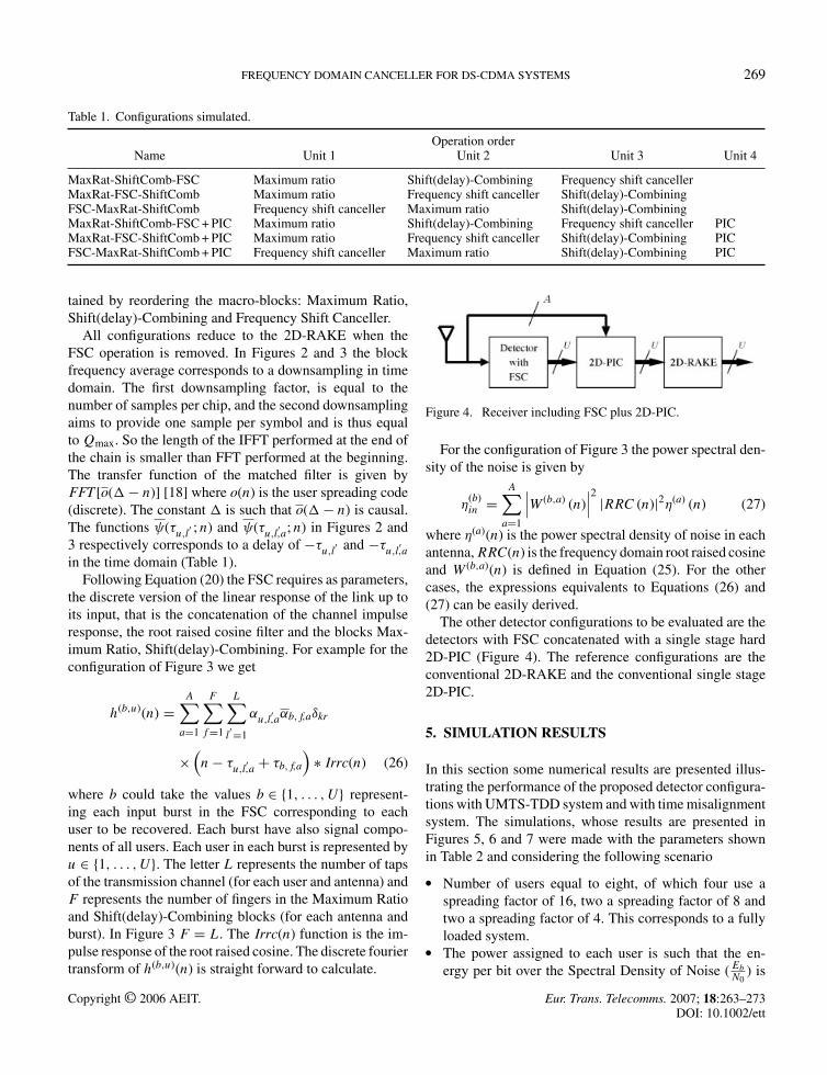
Figure 4. Receiver including FSC plus 2D-PIC.
For the configuration of Figure 3 the power spectral den-sity of the noise is given by
η(b)in =
A∑a=1
∣∣∣W (b,a) (n)∣∣∣2 |RRC (n)|2η(a) (n) (27)
where η(a)(n) is the power spectral density of noise in eachantenna,RRC(n) is the frequency domain root raised cosineand W (b,a)(n) is defined in Equation (25). For the othercases, the expressions equivalents to Equations (26) and(27) can be easily derived.
The other detector configurations to be evaluated are thedetectors with FSC concatenated with a single stage hard2D-PIC (Figure 4). The reference configurations are theconventional 2D-RAKE and the conventional single stage2D-PIC.
5. SIMULATION RESULTS
In this section some numerical results are presented illus-trating the performance of the proposed detector configura-tions with UMTS-TDD system and with time misalignmentsystem. The simulations, whose results are presented inFigures 5, 6 and 7 were made with the parameters shownin Table 2 and considering the following scenario
� Number of users equal to eight, of which four use aspreading factor of 16, two a spreading factor of 8 andtwo a spreading factor of 4. This corresponds to a fullyloaded system.
� The power assigned to each user is such that the en-ergy per bit over the Spectral Density of Noise (Eb
N0) is
Copyright © 2006 AEIT. Eur. Trans. Telecomms. 2007; 18:263–273DOI: 10.1002/ett

270 L. GONCALVES AND A. GAMEIRO
Figure 5. Single antenna, UMTS-TDD system.
identical for all and therefore the power assigned to theusers with spreading factor of eight and four is respec-tively 3 db and 6 db above the power assigned to the userwith spreading factor of 16.
The results presented are only for the users with a spread-ing factor equal to 16. For the users with spreading factorof four the performance is slightly worst due interpath in-terference. The results of Figures 6 and 7 are presented interms of the normalised Eb
Noin db, which is defined as the
actual power efficiency minus the diversity antenna arraygain 10 log10 A, where A is the number of array elements.This is done to ensure that the algorithm is compared on a
Figure 6. Beamforming, circular array, four antennas (A), UMTS-TDD system.
Figure 7. Spatial diversity, four antennas (A), UMTS-TDDsystem.
fair basis and to be able to separate the performance gainsdue to the algorithm and configuration from the gains dueto the existence of diversity only.
For the single antenna case, all configurations exhibitthe same performance. For the case of multi-elementarray the performance differs according to the relativepositions of the Shift(delay)-Combining and FSC. Thenthe configurations FSC-MaxRat-ShiftComb and MaxRat-FSC-ShiftComb have the same performance. Althoughthe configuration MaxRat-ShiftComb-FSC gives the worstperformance, in terms of complexity this configuration onlyneeds 1/A the amount of matrix inversions in relation to theFSC-MaxRat-ShiftComb configuration (A is the number ofantennas).
From Figures 5, 6 and 7 we observe that either for thecases of beamforming or diversity, the use of the FSC pro-vides considerable gains relatively to the 2D-RAKE andnamely eliminates the bit error rate (BER) floor.
For the single antenna case the use of the FSC outper-forms the PIC for moderate to high values of Eb
No. The
same behaviour is observed with multiple antennas but for
Table 2. Simulation parameters settings.
Redundant bands 18Number of taps (per user and antenna) 2Velocity 50 Km/hPath loss exponent 3.7Maximum delay spread 2.0 �sNumber of samples per chip 4Line of sight distance 300 mNumber of array elements 4
Copyright © 2006 AEIT. Eur. Trans. Telecomms. 2007; 18:263–273DOI: 10.1002/ett

FREQUENCY DOMAIN CANCELLER FOR DS-CDMA SYSTEMS 271
Figure 8. Single antenna with time misalignment system.
higher values of EbNo
(not shown in the plots of Figures 6and 7).
The use of the FSC with multiple antennas leads to gainscompared to the single antenna case a 1.5 db gain for auncoded BER of 10−2 for the beamforming case, and up to6 db for the diversity case.
The concatenation of the FSC and 2D-PIC detector nearlyeliminates all the interference and the performance ob-served is almost coincident with the single-user 2D-RAKEperformance.
In Figures 8, 9 and 10 are presented the simulation re-sults for system with time misalignment. In relation to syn-
Figure 9. Beamforming, circular array, four antennas (A) withtime misalignment system.
Figure 10. Spatial diversity, four antennas (A) with time mis-alignment system.
chronous system (UMTS-TDD), the channel profile foreach user and burst suffers a delay with a uniform distri-bution from 0 to 1 �s.
As expected the results are worst than in UMTS-TDDsystem, but for multi-antenna scenario the performance ap-proaches the 2D-RAKE single-user case.
6. CONCLUSIONS
In this paper we proposed a frequency domain, linear multi-user canceller able to operate with multi-rate signals. Thecanceller takes advantage of the frequency redundancy in-herent in DS-SS signals, and the multi-rate extension wasdone by verifying that with UMTS-TDD like systems asignal with spreading factor which is a submultiple of themaximum spreading factor can be decomposed in sev-eral DS-SS signals each one with maximum spreadingfactor.
The performance of the canceller was evaluated forseveral configurations, either as a stand alone unit orconcatenated with a PIC. The results have shown con-siderable improvements relatively to the 2D-RAKE, andwith the application of multiple antennas in diversity casea considerable performance improvements was achieved.Furthermore when concatenated with a 2D-PIC, theperformance achieved for both beamforming and diversitycase is very close to the single-user bound and thus theFSC turns out to be a feasible candidate for interferencecancellation and as a mean to provide clean signals to alow complexity PIC that can remove all the interference.
Copyright © 2006 AEIT. Eur. Trans. Telecomms. 2007; 18:263–273DOI: 10.1002/ett

272 L. GONCALVES AND A. GAMEIRO
APPENDIX A: COMPUTATION OF THEGRADIENT AND HESSIAN
The function to be minimised in Equuation (16) is
F({αi}i∈{−I,...,I}) = Ls U∑
u=2
∣∣∣∣∣I∑
i=−I
(αiG
(u)iB
G(1)iB
)∣∣∣∣∣2
+I∑
i=−I
|αi|2 ηiniB∣∣∣G(1)iB
∣∣∣2 (A.1)
Assume the following complex constant and positive realconstant
Zui =G
(u)iB
G(1)iB
(A.2)
Xi = ηiniB∣∣∣G(1)iB
∣∣∣2 (A.3)
Given a complex function P then |P |2 = PP (It couldbe identified such functions in Equation (A1)) then by in-spection of Equation (A1) F is a real function dependenton the complex variables {αi} and {αi}. In this type of func-tions the stationary points could be taken by the gradient inrelation to {αi} or {αi} [19]. The gradient in relation to {αi}is preferable because the resultant gradient is dependant onthe variables αi.
It is given that the following formula ∂K({zi,zi}i)∂zk
=12
[∂K∂xk+ j ∂K
∂yk
]where zk = xk + jyk [19] and K is a real
function of complex variables.Each element of the gradient vector is
∂F({αi}i∈{−I,...,I})
∂αk= Ls
U∑u=2
(Zuk
I∑i=−I
(Zui αi
))+ αkXk(A.4)
where the gradient vector is ∇F ({αi}i∈{−I,...,I}) =[∂F({αi}i∈{−I,...,I})
∂αk
]k∈{−I,...,I}
.
The Hessian Matrix is given by
He =[∂F
({αi}i∈{−I,...,I})∂αc∂αk
]k∈{−I,...,I},c∈{−I,...,I}
(A.5)
The coefficients of the Hessian Matrix are
∂F({αi}i∈{−I,...,I})∂αc∂αk
= LsU∑u=2
ZucZuk +Xk c = k (A.6)
and
∂F({αi}i∈{−I,...,I})∂αc∂αk
= LsU∑u=2
ZucZuk c �= k (A.7)
The proof that the Hessian is positive definite is impliedby the definition of Matrix positive definite. Then given thevector, x = [x−I , . . . , x0, . . . , xI ]T the following inequal-ity is always true for x ∈ C
2I+1/0
[xH [He] x
] = Ls U∑u=2
∣∣∣∣∣∣I∑
k=−IxkZ
uk
∣∣∣∣∣∣2
+I∑
k=−IXk |xk|2 > 0(A.8)
when the superscript H means transpose-conjugate. Then thematrix He is Hermitian definite positive and can be invertedby Cholesky decomposition. The Hessian matrix is Hermi-tian definite positive in all the domain of {αi} and thereforethe function F is strictly convex [20]. By the same processcan be proved that the Hessian matrix of the functionF withthe restriction
∑Ii=−I αi(f ) = 1 (we proved only for F ) is
strict convex, and the minimum at Equation (18) is global.
ACKNOWLEDGEMENT
The authors would like to acknowledge Dr Cipriano Lomba and DrJonathan Rodriguez for their help in the preparation of the paper.This work was supported by a PhD Grant from PRAXIS XXI,Fundacao para a Ciencia e Tecnologia and the projects ASILUMand VISEF.
REFERENCES
1. Kohno R, Meidan R, Milstein LB. Spread spectrum access methodsfor wireless communications. IEEE Communications Magazine 1995;33(1):58–67.
2. Verdu S. Minimum probability of error for asynchronous gaussianmultiple-access channels. IEEE Transactions of Information Theory1986; 32(1):85–96.
3. Xie Z, Short RT, Rushforth CK. A family of suboptimum detectors forcoherent multiuser communications. IEEE Journal of Selected Areasin Communications 1990; 8(4):683–690.
4. Klein A, Baier PW. Linear unbiased data estimation in mobile radiosystems applying CDMA. IEEE Journal of Selected Areas in Com-munications 1993; 11(7): 1058–1066.
5. Duel-Hallen A. A family of multiuser decision-feedback detectors forasynchronous code-division multiple-access channels. IEEE Transac-tions on Communications 1995; 43(234):421–434.
6. Guo D. Linear Parallel Interference Cancellation in CDMA. M.Eng.Thesis, National University of Singapore, December 1998.
7. Divsalar D, Simon MK, Raphaeli D. Improved parallel interfer-ence cancellation for CDMA. IEEE Transactions on Communications1998; 46(2):258–268.
Copyright © 2006 AEIT. Eur. Trans. Telecomms. 2007; 18:263–273DOI: 10.1002/ett

FREQUENCY DOMAIN CANCELLER FOR DS-CDMA SYSTEMS 273
8. Gardner WA. Cyclostationarity in Communications and Signal Pro-cessing. IEEE PRESS, 1994.
9. Gardner WA. Cyclic wiener filtering: theory and method. IEEE Trans-actions on Communications 1993; 41(1):151–163.
10. Zhang J, Wong KM, Luo ZQ, Ching PC. Blind adaptative FRESHfiltering for signal extraction. IEEE Transactions on Signal Processing1999; 47(5):1397–1402.
11. Whitehead J, Takawira F. Blind adaptative multiuser detection for peri-odically time varying interference suppression. In IEEE Wireless Com-munication and Networking Conference, (New Orleans, LA, USA),13–17 March 2005.
12. Winters JH. Smart antennas for wireless systems. IEEE Personal Com-munications 1998; 5(1):23–27.
13. Godara LC. Applications of antenna arrays to mobile communications,Part I: Performance Improvement, Feasibility, and System Consider-ations. Proceedings of IEEE, July 1997.
AUTHORS’ BIOGRAPHIES
Luis Goncalves received his Licenciatura (5 years degree) in Electronics Engineering and Telecommunications from Universityof Aveiro in 1991. He worked in the industry in companies like Texas Instruments and Blaupunkt until 1999. He is a researcherat Telecommunications Institute at Aveiro from 1999. He is an Assistant Lecturer at University of Madeira in the Department ofMathematics and Engineering since 2004. He is currently working towards the Ph.D. degree. At moment he has 10 published papers.His current research activities involve multi-user detection and cyclostationarity.
Atılio Gameiro received his Licenciatura (five-year course) and his Ph.D. from the University of Aveiro in 1985 and 1993, respectively.He is currently a Professor in the Department of Electronics and Telecommunications of the University of Aveiro, and a researcher at theTelecommunications Institute at Aveiro, where he is a head of group. His main interests lie in signal processing techniques for digitalcommunications and communication protocols. Within this research line, he has done work for optical and mobile communications,at either the theoretical or experimental level, and has published over 150 technical papers in international journals and conferences.His current research activities involve space-time frequency and cross-layers algorithms/techniques for wireless systems, and cognitiveradio.
14. Huang HC. Combined multipath processing, array processing, andmultiuser detection for DS-CDMA channels. Ph. D. Thesis, Faculty ofPrinceton, Princeton, USA, 1996.
15. “3GPP TS 25.223,” “Spreading and modulation (TDD)”, January2004.
16. Litva J, Lo TK-Y. Digital Beamforming in Wireless Communications,(1st edn). Artech House Publishers: Boston, USA, 1996.
17. Liberti JC, Rappaport TS. Smart Antennas for Wireless Communica-tions: IS-95 and Third Generation CDMA Applications. Prentice Hall:New Jersey, USA, 1999.
18. Turin GL. An introduction to matched filters. IRE Transactions onInformation Theory 1960; 6(3):311–329.
19. Brandwood BADH. A complex gradient operator and its applicationin adaptative array theory. IEE Proc., Pts. F and H 1983; 130:11–16.
20. Pchenitchny B, Daniline Y. Methodes Numeriques dans les ProblemesD’Extremum. Editions MIR, Moscou, 1977.
Copyright © 2006 AEIT. Eur. Trans. Telecomms. 2007; 18:263–273DOI: 10.1002/ett