multi-view passive 3d face acquisition device
TRANSCRIPT
Multi-view passive 3D face acquisition device
L.J. SpreeuwersSignals and Systems Group, Faculty of EEMCS
University of TwenteP.O. Box 217, 7500 AE Enschede, Netherlands
Abstract: Approaches to acquisition of 3D facial data include laser scanners, struc-tured light devices and (passive) stereo vision. The laser scanner and structured lightmethods allow accurate reconstruction of the 3D surface but strong light is projectedon the faces of subjects. Passive stereo vision based approaches do not require stronglight to be projected, however, it is hard to obtain comparable accuracy and robustnessof the surface reconstruction. In this paper a passive multiple view approach using5 cameras in a ’+’ configuration is proposed that significantly increases robustnessand accuracy relative to traditional stereo vision approaches. The normalised crosscorrelations of all 5 views are combined using direct projection of points instead ofthe traditionally used rectified images. Also, errors caused by different perspectivedeformation of the surface in the different views are reduced by using an iterative re-construction technique where the depth estimation of the previous iteration is used towarp the windows of the normalised cross correlation for the different views.
1 Introduction
Face recognition has been a very active research field for the last 15 years since Turk andPentland published their face recognition using PCA in 1993 and impressive progress hasbeen achieved. However, illumination, pose and aging remain serious problems. Recently,3D face recognition has begun to develop and promises improved robustness against il-lumination and pose variations. Devices used for 3D face acquisition are mostly laserscanners like the Minolta 910, which was used to acquire the 3D images in the FRGC v2database, or structured light scanners like the viSense from Polygon. Both are active de-vices that use a controlled light source and produce dense reliable 3D measurements withhigh depth accuracy. The disadvantages of these active devices are:
• They project light on the subjects face, which may be an unpleasant experience andis bound to strict regulations to avoid damage to the eyes
• Using projection of light and light patterns does not work well if there are strongexternal light sources, like e.g. the sun
• Theyare not really fit to record videos, because they have a time lag between thefirst and last scanned point in case of the laser scanner and between successivelyrecorded images with different patterns for the structured light approach.
In principle a passive sensor based on stereo vision techniques does not suffer or suffersless from these defects. No strong light needs to be projected on the face and images canbe captured at video speed and there is no lag between different phases of the acquisition.However, classical stereo vision [BBH03] is not really fit for the high resolution imagesrequired for 3D face recognition. In this paper, a multiple view approach is presented thatenables us to reconstruct 3D facial surfaces with high accuracy. Most notably, the accu-racy and robustness are increased by combining measurements from multiple views andallowing perspective deformation of correlation windows using an iterative reconstructionapproach.
In the next section first the basics of 3D reconstruction from stereo vision are briefly ex-plained. Next the most important problems entailed with classical stereo vision are de-scribed and subsequently the expected improvements using the multi-view approach. Thenthe iterative reconstruction approach is presented, followed by experiments and results and,finally, conclusions.
2 Basics of 3D reconstruction from stereo cameras
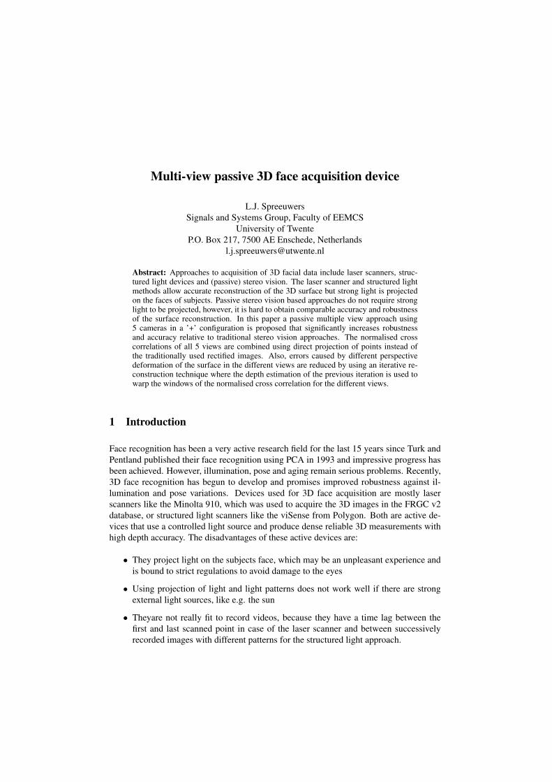
A stereo camera setup consists of 2 cameras. A point P in the 3D world is projectedon both left (Ql) and right images (Qr). If we know the geometric parameters of thecameras, the coordinates of P can be reconstructed from the image-coordinates of Ql andQr using triangulation. This means we have to find corresponding points in the left andright images. Instead of searching the whole images for corresponding points, the epipolarconstraint can be applied: given Ql, all possible candidates for Qr are on a line in the rightimage. This is illustrated in fig.1a.
(a) (b)
Figure 1: a) Stereo camera, projection of point P on image planes and epipolar line; b) Non-vergedcamera configuration: image planes are parallel to baseline and all epipolar lines are horizontal lines.
The images can be warped such that for each point in the left image only points on thesame row in the right image have to be considered. The warped images are called rectifiedimages and the corresponding camera configuration is called the non-verged stereo camera
configuration (see fig.1b). For a non-verged camera system the image planes of the twocameras are parallel to the baseline of the cameras, i.e. the line between the pin-holes. Asa result, all epipolar lines are horizontal lines.
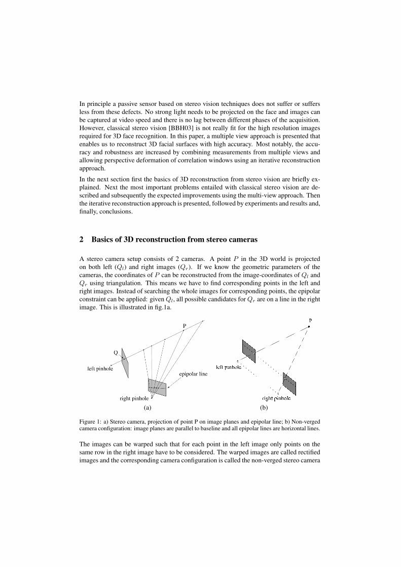
Corresponding points are often found by correlating local neighbourhoods in the rectifiedimages and selecting the points with the highest correlation. The distance between thematching points in the two images is called the disparity and the depth is inverse pro-portional to this disparity. An example of the normalised correlation as a function of thedisparity is given in fig.2.
Figure 2: Normalised correlation as a function of the disparity
An in-depth discussion of classical stereo approaches can be found in [BBH03].
3 Typical problems of classical stereo vision
Areas with little texture In areas with little texture, the correlation based methods givesimilar correlation values for all points. Thus corresponding points cannot be locatedaccurately and, hence the 3d points cannot be reconstructed reliably.
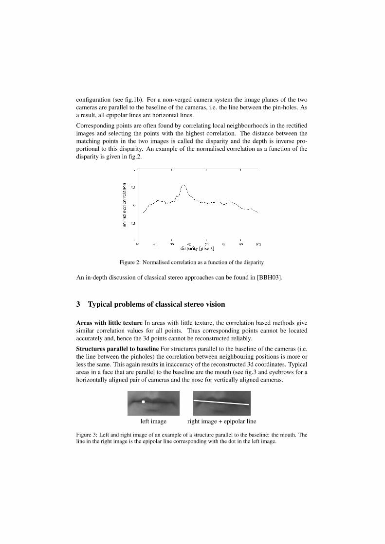
Structures parallel to baseline For structures parallel to the baseline of the cameras (i.e.the line between the pinholes) the correlation between neighbouring positions is more orless the same. This again results in inaccuracy of the reconstructed 3d coordinates. Typicalareas in a face that are parallel to the baseline are the mouth (see fig.3 and eyebrows for ahorizontally aligned pair of cameras and the nose for vertically aligned cameras.
left image right image + epipolar line
Figure 3: Left and right image of an example of a structure parallel to the baseline: the mouth. Theline in the right image is the epipolar line corresponding with the dot in the left image.
Repeating texture Repeating or similar textures along the epipolar lines result in multi-ple maxima for the correlation and no clear best match, which in turn results in possibleincorrect reconstruction of 3d points.
Accuracy of z-measurements The accuracy of the reconstructed 3D coordinates dependson the distance of the 3D object to the cameras. The accuracy in x- and y-directions isinverse proportional to this distance. The accuracy in the z-direction is inverse proportionalto the square of this distance. For a stereo setup for acquisition faces at a distance of about60 [cm], the accuracy in z-direction is 10 times lower than in x- and y-directions.
Occlusions Because both cameras look at the object from different positions, there canbe areas on a curved object that are obscured by other parts of the object. In faces, theseinclude the areas around the nose, below the chin and around the ears. The obscured areasare either invisible in both images or only visible in one of the two images. In both casesit is impossible to determine the corresponding 3D coordinates of points in these areas.
Specular reflections The problem with specular reflections is that the position in the im-ages depends on the viewing direction of the cameras. If the camera moves, the positionof the specular reflection spot appears to wander over the object. If the specular reflectionspots are used for stereo matching, incorrect 3D positions result.
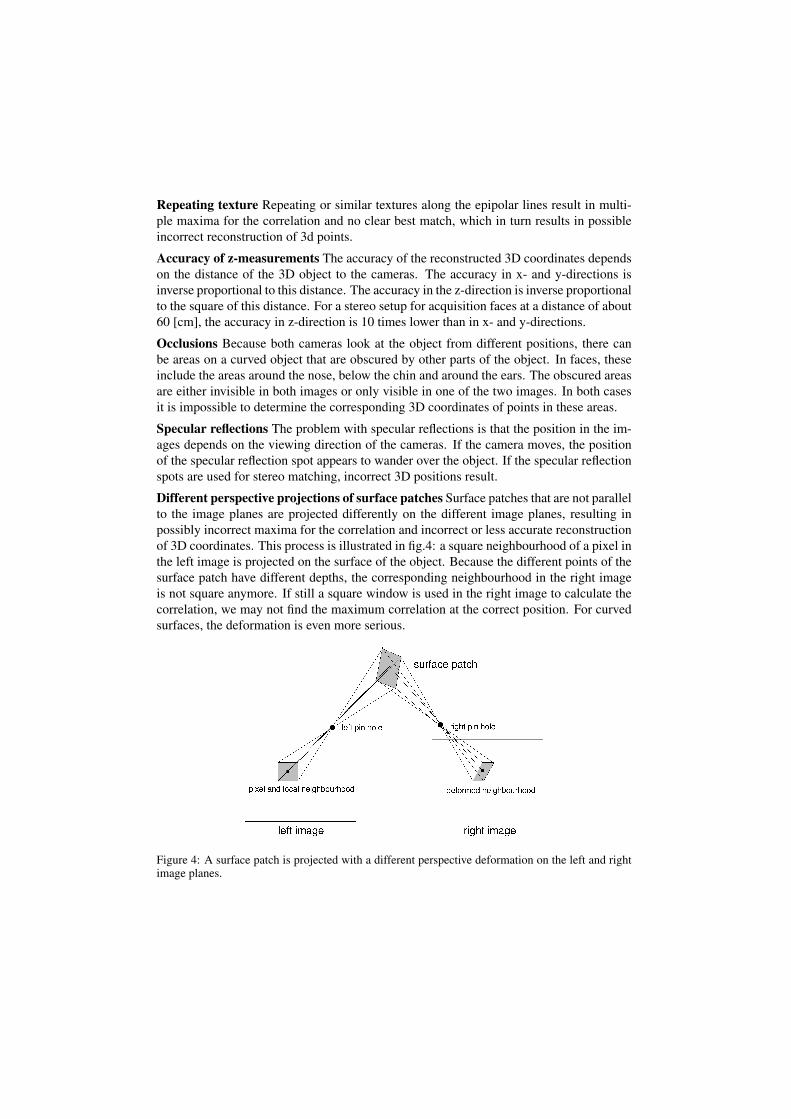
Different perspective projections of surface patches Surface patches that are not parallelto the image planes are projected differently on the different image planes, resulting inpossibly incorrect maxima for the correlation and incorrect or less accurate reconstructionof 3D coordinates. This process is illustrated in fig.4: a square neighbourhood of a pixel inthe left image is projected on the surface of the object. Because the different points of thesurface patch have different depths, the corresponding neighbourhood in the right imageis not square anymore. If still a square window is used in the right image to calculate thecorrelation, we may not find the maximum correlation at the correct position. For curvedsurfaces, the deformation is even more serious.
Figure 4: A surface patch is projected with a different perspective deformation on the left and rightimage planes.
4 Advantages of multi-view approach
Areas with little texture In areas with little texture, having available more measurementshelps to improve robustness and accuracy of the 3d reconstruction.
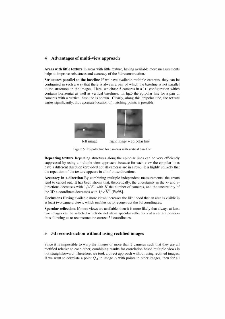
Structures parallel to the baseline If we have available multiple cameras, they can beconfigured in such a way that there is always a pair of which the baseline is not parallelto the structures in the images. Here, we chose 5 cameras in a ’+’ configuration whichcontains horizontal as well as vertical baselines. In fig.5 the epipolar line for a pair ofcameras with a vertical baseline is shown. Clearly, along this epipolar line, the texturevaries significantly, thus accurate location of matching points is possible.
left image right image + epipolar line
Figure 5: Epipolar line for cameras with vertical baseline
Repeating texture Repeating structures along the epipolar lines can be very efficientlysuppressed by using a multiple view approach, because for each view the epipolar lineshave a different direction (provided not all cameras are in a row). It is highly unlikely thatthe repetition of the texture appears in all of those directions.
Accuracy in z-direction By combining multiple independent measurements, the errorstend to cancel out. It has been shown that, theoretically, the uncertainty in the x- and y-directions decreases with 1/
√K, with K the number of cameras, and the uncertainty of
the 3D z-coordinate decreases with 1/√
K3 [For98].
Occlusions Having available more views increases the likelihood that an area is visible inat least two camera views, which enables us to reconstruct the 3d coordinates.
Specular reflections If more views are available, then it is more likely that always at leasttwo images can be selected which do not show specular reflections at a certain positionthus allowing us to reconstruct the correct 3d coordinates.
5 3d reconstruction without using rectified images
Since it is impossible to warp the images of more than 2 cameras such that they are allrectified relative to each other, combining results for correlation based multiple views isnot straightforward. Therefore, we took a direct approach without using rectified images.If we want to correlate a point QA in image A with points in other images, then for all

points of a local neighbourhood of QA and all possible depths we calculate the corre-sponding points in the other images, get the pixel values by interpolation and perform thecorrelation. This means we do not find the maximum correlation as a function of the dis-parity, but directly as a function of the depth. This makes combination of the correlationresults straightforward. As an extra bonus, this approach allows us to tackle the problemof the perspective deformation of the correlation windows by using an iterative approachwhere the previous estimate of the 3D surface is used to modulate the relative depths of thepoints within the correlation mask. This approach is more computationally expensive thanthe process with rectified images, but by using a clever caching approach, the differencecan be minimised. This caching means pre-calculation of the interpolated gray levels forcorresponding points for all possible depths in a certain range with a certain step size indepth. Calculation of this depth-gray level cache takes more time than calculation of therectified images, but, generally, still far less time than the normalised correlation processand thus 3D reconstruction is not so much slower than the traditional approach using rec-tified images. The construction of the cache for a single pixel for two images is illustratedin fig.6. As can be seen in the figure, for each possible depth of pixel Q in the left im-age, the corresponding position in the right image is calculated, the gray level is obtainedby interpolation and stored in the cache. Normalised correlation is then calculated for allpossible depths within the set range.
Figure 6: Construction of the depth-gray level cache for 1 pixel and 2 images
6 Experiments and results
6.1 The acquisition system
The system we designed consists of 5 high resolution (1280x960) video cameras that con-nect to a PC through fire-wire connections. The cameras are synchronised externally toallow them to capture images simultaneously. The cameras are configured in a ’+’ config-uration with one centre camera, one left, one right one upper and one lower camera. Bychoosing the ’+’ configuration, there are no structures that are parallel to the baselines of

all camera pairs simultaneously. A photograph of the 5 camera system and the setup forrecording a set of images of a subject are shown in fig.7.
Figure 7: 5 camera system and setup for recording a set of images of a subject
Calibration is performed on pairs of cameras relative to the centre camera. The calibra-tion toolbox of OpenCV [Ope] is used, which is a quite advanced and accurate calibrationapproach using multiple recordings of a chessboard calibration object.The calibration tool-box is mainly based on [Zha99].
6.2 Experiments
In this section, a number of experiments are proposed to show the proposed multi-viewapproach performs as we expect. The following experiments are presented:
1. Depth estimation of a single point: stereo vs. multi-view for a point in the moutharea (texture parallel to baseline for stereo)
2. Depth estimation of a single point: stereo vs. multi-view for a point in an area withlittle texture (forehead)
3. Depth estimation of a single point: stereo vs. multi-view for a point on a stronglycurved surface (bridge of the nose)
4. Depth estimation of a horizontal line iterative vs. non-iterative approach
For all of these experiments, except for experiment 3, the size of the correlation windowwas set to 21x21 pixels, because this proved a reasonable compromise between robustnessof correlation and accuracy.
Experiment 1 A single point in the central image is picked and the correlation as a func-tion of depth is shown for all 4 camera pair combinations with the central camera. Theselected point is on the mouth (see fig.3) and for the horizontal camera pairs we expect a

large range in the depth where the normalised correlation is more or less constant, whilefor the camera pairs with vertical baseline we expect a relatively sharp peak. In fig.8 thenormalised correlation as a function of depth is shown for the described point for four dif-ferent camera pairs, two with horizontal and two with vertical baselines and a combinationof the four correlations by simple averaging.
Figure 8: Normalised correlation as a function of depth for four camera pairs and a combination fora point on the mouth
Clearly, the two cameras with horizontal baselines show a relatively flat and high correla-tion near the actual depth of 533 [mm]. Just as expected it is difficult to obtain an accuratedepth estimate using just those cameras. The camera pairs with vertical baseline allowgood recovery of the depth. Combination of all four curves by averaging gives a nice peakas well. Because small deviations are are averaged out, we may expect that this curveallows more accurate recovery of the depth than the individual curves.
Experiment 2 Again a single point in the central image is picked and the correlation asa function of depth is shown for all 4 camera pair combinations with the central camera.The selected point is on the forehead, an area with little distinguishing texture and for allcamera pairs we expect a large range in the depth where the normalised correlation is moreor less constant. In fig.9 the normalised correlation as a function of depth is shown for thedescribed point for four different camera pairs, two with horizontal and two with verticalbaselines and a combination of the four correlations by simple averaging.
From the individual curves it is difficult to reliably determine the correct depth. From thecombined curve, a unique maximum of the normalised correlation can be found, however,the curve does not show the desired sharp peak. As expected, depth estimation for areaswith little texture and constant illumination improves by using multiple views, but not asmuch as in the case with the textures parallel to the baseline.
Experiment 3 Again a single point in the central image is picked and the correlation as afunction of depth is shown for all 4 camera pair combinations with the central camera. Theselected point is on the bridge of the nose, an area with strong curvature and we may expect
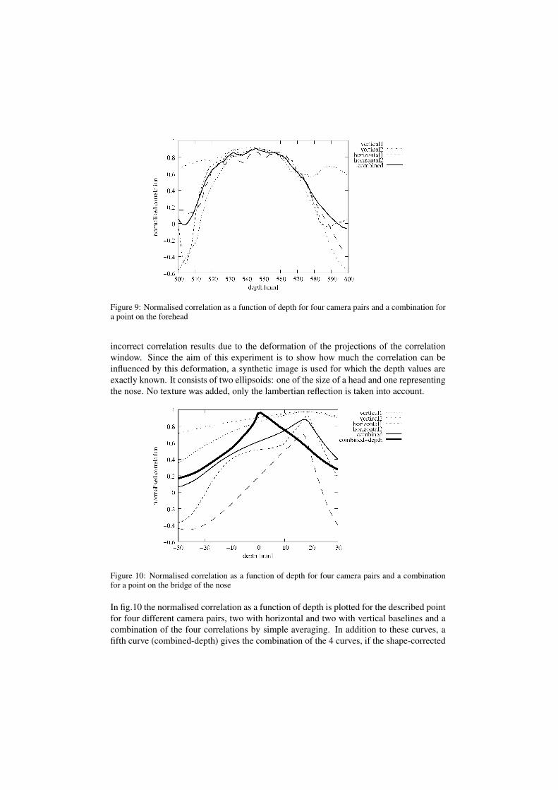
Figure 9: Normalised correlation as a function of depth for four camera pairs and a combination fora point on the forehead
incorrect correlation results due to the deformation of the projections of the correlationwindow. Since the aim of this experiment is to show how much the correlation can beinfluenced by this deformation, a synthetic image is used for which the depth values areexactly known. It consists of two ellipsoids: one of the size of a head and one representingthe nose. No texture was added, only the lambertian reflection is taken into account.
Figure 10: Normalised correlation as a function of depth for four camera pairs and a combinationfor a point on the bridge of the nose
In fig.10 the normalised correlation as a function of depth is plotted for the described pointfor four different camera pairs, two with horizontal and two with vertical baselines and acombination of the four correlations by simple averaging. In addition to these curves, afifth curve (combined-depth) gives the combination of the 4 curves, if the shape-corrected

correlation windows are taken into account using the true depth map of the face. In-stead of the absolute depth, the depth relative to the true depth is given on the horizontalaxis. As can be seen, the maxima of the normalised correlations show a significant off-set. This is the effect that can be expected due to deformation of the correlation windows.If the corrected correlation windows are used, the maximum is on the correct position(combined-depth curve). Incidentally, since the nose is primarily a vertical structure, itis to be expected that the camera pairs with horizontal baselines give a more pronouncedpeak, which is indeed the case.
Experiment 4 In this experiment the synthetic face model is used, but a piece of a horizon-tal line across the nose is reconstructed. This will better illustrate the correction resultingfrom the iterative reconstruction approach. Figure 11 shows the true depth along the lineand the estimated depth without applying the iterative approach (iteration 0) and the iter-ations 1 and 4 where for each iteration the depth map of the previous iteration is used tomodulate the shape of the correlation window. Finally, the reconstructed depth when usingthe true depth to shape the correlation windows is plotted in the ”using true depth” curve.
Figure 11: Depth reconstruction along a horizontal line across the nose using the iterative approach
From figure 11 it is clear that the normal reconstruction (iteration 0 curve) gives seriousdeviations from the ground truth. The iterative approach (iteration 1 and 4 curves) resultsin a significantly better approximation of the ground truth, although not as good as thereconstruction that applies the true surface to warp the correlation windows, which ap-proximates the true depth very well. The difference between the 4th and the 1st iterationis rather small. We found that normally the first iteration gives the largest improvement.
6.3 Reconstruction of a full face
The method was applied to obtain a reconstruction of a complete face. In figure 12, therecorded images obtained with the 5 cameras in a ’+’ configuration are shown.

Figure 12: Images obtained using the 5 camera ’+’ configuration
In figure 13a a reconstruction is shown using the 5 views, while in figure 13b 3 iterationswere performed where each time the surface of the previous iteration was used to modu-late the depths of the correlation windows. Clearly the latter gives a smoother and moreaccurate result as already was shown in the previous section with reconstructions of singlelines. Note that the ridges near the bridge have gone and that the nose has a different (andmore correct) shape in figure 13b. The contours that are still visible are mostly resultingfrom the fact that for computational efficiency, the face was divided in patches of about9x9 [mm].
The complete reconstruction of a face to a resolution of 0.5 [mm] in x-, y- and z-directiontakes approximately 8 minutes on a single core Pentium 4 at 2.8 GHz.
7 Conclusion
We show that using a multi-view approach to 3d face reconstruction overcomes many ofthe typical problems of classical stereo reconstruction. The multi-view approach signifi-cantly improves robustness and accuracy of the reconstruction in areas with little textureand where in the stereo-view approach structures are parallel to the baseline of the cam-eras. Furthermore, we propose an approach to 3d reconstruction that does not use rectifiedimages, but finds corresponding points in the other images for all depths. This approachallows combination of the results of multiple views more easily and also allows takinginto account the different shapes of correlation windows in the different images using aniterative approach where the surface estimation of the previous iteration is used to ”shape”the correlation windows which results in a significant reduction of the error of the depthestimation. The proposed methods have been implemented using a depth-gray level cachewhich allows for relatively efficient calculation. Several experiments show that the pro-posed approach results in the expected improvements relative to classical stereo.

(a) (b)
Figure 13: Reconstructions of a complete face; a) single iteration, b) after 3 iterations
References
[BBH03] Myron Z. Brown, Darius Burschka, and Gregory D. Hager. Advances in ComputationalStereo. IEEE Transactions on Pattern Analysis and Machine Intelligence, 25(8):993–1008, 2003.
[For98] W. Forstner. On the Theoretical Accuracy of Multi Image Matching, Restoration andTriangulation. In Festschrift zum 65. Geburtstag von Prof. Dr.-Ing. mult. G. Konecny.Institut fur Photogrammetrie, Universitat Hannover, 1998.
[Ope] Open Computer Vision Library. http://sourceforge.net/projects/opencvlibrary.
[Zha99] Zhengyou Zhang. Flexible Camera Calibration by Viewing a Plane from Unknown Ori-entations. In Proceeedings of the International Conference on Computer Vision, pages666–673, Kerkya, Corfu, Greece, 20-25 September 1999. IEEE Computer Society.