multicam a2mc manual
TRANSCRIPT

MulticamVision System
Manual
Revised April, 2019, © Multicam Systems Pty Ltd
All rights reserved. No part of this document may be reproduce or transmitted in any form or byany means, electronic, mechanical, photocopying, recording, or otherwise, without prior written
permission of Multicam Systems Pty Ltd.

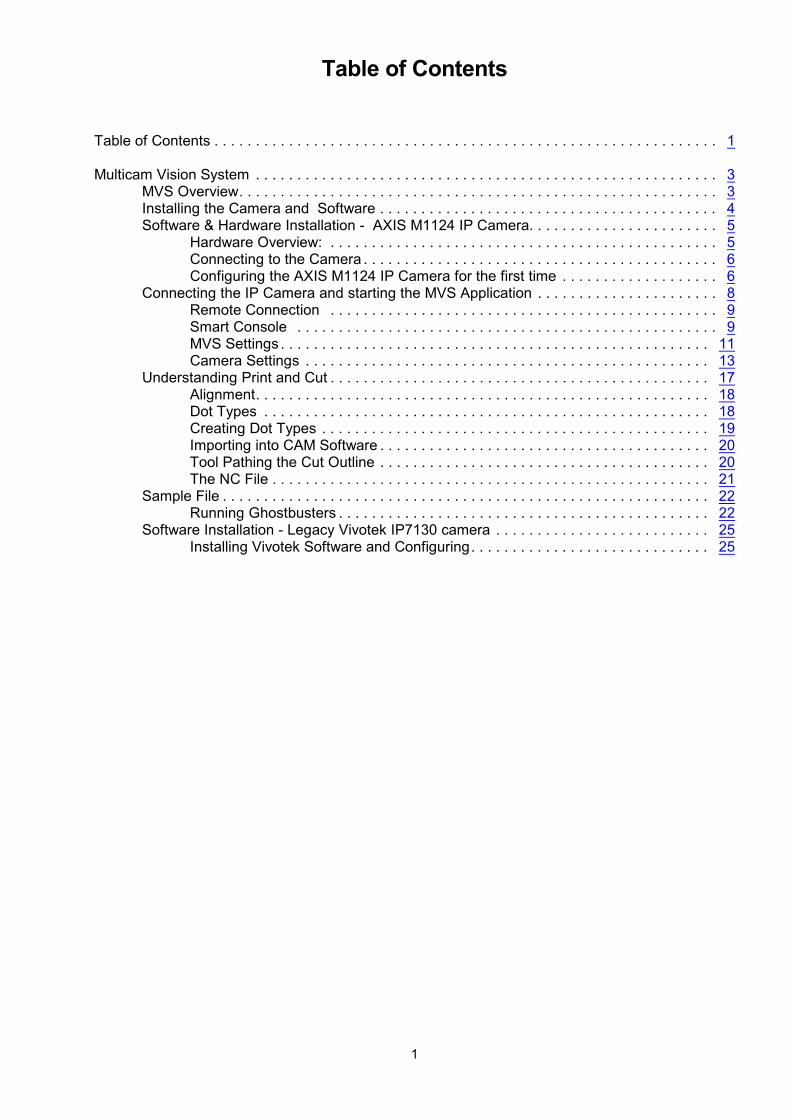
Table of Contents
Table of Contents . . . . . . . . . . . . . . . . . . . . . . . . . . . . . . . . . . . . . . . . . . . . . . . . . . . . . . . . . . . . . 1
Multicam Vision System . . . . . . . . . . . . . . . . . . . . . . . . . . . . . . . . . . . . . . . . . . . . . . . . . . . . . . . . 3MVS Overview. . . . . . . . . . . . . . . . . . . . . . . . . . . . . . . . . . . . . . . . . . . . . . . . . . . . . . . . . . 3Installing the Camera and Software . . . . . . . . . . . . . . . . . . . . . . . . . . . . . . . . . . . . . . . . . 4Software & Hardware Installation - AXIS M1124 IP Camera. . . . . . . . . . . . . . . . . . . . . . . 5
Hardware Overview: . . . . . . . . . . . . . . . . . . . . . . . . . . . . . . . . . . . . . . . . . . . . . . . 5Connecting to the Camera . . . . . . . . . . . . . . . . . . . . . . . . . . . . . . . . . . . . . . . . . . . 6Configuring the AXIS M1124 IP Camera for the first time . . . . . . . . . . . . . . . . . . . 6
Connecting the IP Camera and starting the MVS Application . . . . . . . . . . . . . . . . . . . . . . 8Remote Connection . . . . . . . . . . . . . . . . . . . . . . . . . . . . . . . . . . . . . . . . . . . . . . . 9Smart Console . . . . . . . . . . . . . . . . . . . . . . . . . . . . . . . . . . . . . . . . . . . . . . . . . . . 9MVS Settings . . . . . . . . . . . . . . . . . . . . . . . . . . . . . . . . . . . . . . . . . . . . . . . . . . . . 11Camera Settings . . . . . . . . . . . . . . . . . . . . . . . . . . . . . . . . . . . . . . . . . . . . . . . . . 13
Understanding Print and Cut . . . . . . . . . . . . . . . . . . . . . . . . . . . . . . . . . . . . . . . . . . . . . . 17Alignment. . . . . . . . . . . . . . . . . . . . . . . . . . . . . . . . . . . . . . . . . . . . . . . . . . . . . . . 18Dot Types . . . . . . . . . . . . . . . . . . . . . . . . . . . . . . . . . . . . . . . . . . . . . . . . . . . . . . 18Creating Dot Types . . . . . . . . . . . . . . . . . . . . . . . . . . . . . . . . . . . . . . . . . . . . . . . 19Importing into CAM Software . . . . . . . . . . . . . . . . . . . . . . . . . . . . . . . . . . . . . . . . 20Tool Pathing the Cut Outline . . . . . . . . . . . . . . . . . . . . . . . . . . . . . . . . . . . . . . . . 20The NC File . . . . . . . . . . . . . . . . . . . . . . . . . . . . . . . . . . . . . . . . . . . . . . . . . . . . . 21
Sample File . . . . . . . . . . . . . . . . . . . . . . . . . . . . . . . . . . . . . . . . . . . . . . . . . . . . . . . . . . . 22Running Ghostbusters . . . . . . . . . . . . . . . . . . . . . . . . . . . . . . . . . . . . . . . . . . . . . 22
Software Installation - Legacy Vivotek IP7130 camera . . . . . . . . . . . . . . . . . . . . . . . . . . 25Installing Vivotek Software and Configuring. . . . . . . . . . . . . . . . . . . . . . . . . . . . . 25
1

2

Multicam Vision System
The Multicam Vision System (MVS) is an optional accessory aimed at companies that require theability to profile cut pre printed designs on rigid board. The primary application of the MVS systemis digital print finishing where the camera is used to quickly locate registration marks and adjustthe machine cutting path to achieve exact alignment with the printed shapes. It includesnon-linear/linear distortion, skew and rotation correction and is tightly integrated in to the A2MCcontroller of the machine.
To use the MVS you will require the following options;! MVS Camera mounted on the machine! Activated MVS software.
The following pages describe the use of the Multicam Vision System.
MVS OverviewThe Multicam Vision System (MVS) allows for the automatic alignment and correction of printingerrors in Cut to Print applications. It handles locating and rotating the image as well as adjustingfor X and/or Y stretching and has a very easy to use visual interface that is connected to theA2MC via the local area network enabling very fast and smooth jogging and positioning.MVS operates in full colour with a very large viewing area for ease of use. It is able to operate withthree different types of location dots to avoid the problems associated with getting the sequencingof dots mixed up or incorrect placement of the printed sheet on the machine bed.
The camera only requires a single CAT5 cable connection to the computer so it can be quickly andeasily retrofitted to any existing A2MC controlled machine.
The Multicam Vision System is powered by A2MC vision registration software (MVS App) whichoffers full non-linear/linear distortion, skew and rotation correction system.
3

Installing the Camera and SoftwareBefore commencing, device drivers for the camera must be installed on the computer that will beused with the Multicam machine as your print-to-cut workstation.
You cannot proceed until the drivers are installed for the camera.
4

AXIS M1124 IP Camera
PoE injector
Software & Hardware Installation - AXIS M1124 IP Camera
When installing an AXIS M1124 IP camera for the Multicam Vision System you will need thefollowing components.
You will also need;
CAT 5 Cable run from camera through the machine to PoE injectorMounting Bracket
Hardware Overview:
AXIS M1124 IP Camera1. Zoom Puller2. Focus Ring3. Power Connecter4. Control button5. Network connector6. Power LED7. Status LED8. Network LED9. microSD slot10. Iris connector11. I/O connector12. ¼" Screw Mount
PoE Injector1. Power + Data Out2. LAN in3. Power LED4. DC 48v
5
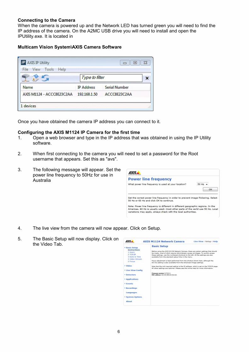
Connecting to the CameraWhen the camera is powered up and the Network LED has turned green you will need to find theIP address of the camera. On the A2MC USB drive you will need to install and open theIPUtility.exe. It is located in
Multicam Vision System\AXIS Camera Software
Once you have obtained the camera IP address you can connect to it.
Configuring the AXIS M1124 IP Camera for the first time1. Open a web browser and type in the IP address that was obtained in using the IP Utility
software.
2. When first connecting to the camera you will need to set a password for the Rootusername that appears. Set this as "avs".
3. The following message will appear. Set thepower line frequency to 50Hz for use inAustralia
4. The live view from the camera will now appear. Click on Setup.
5. The Basic Setup will now display. Click onthe Video Tab.
6
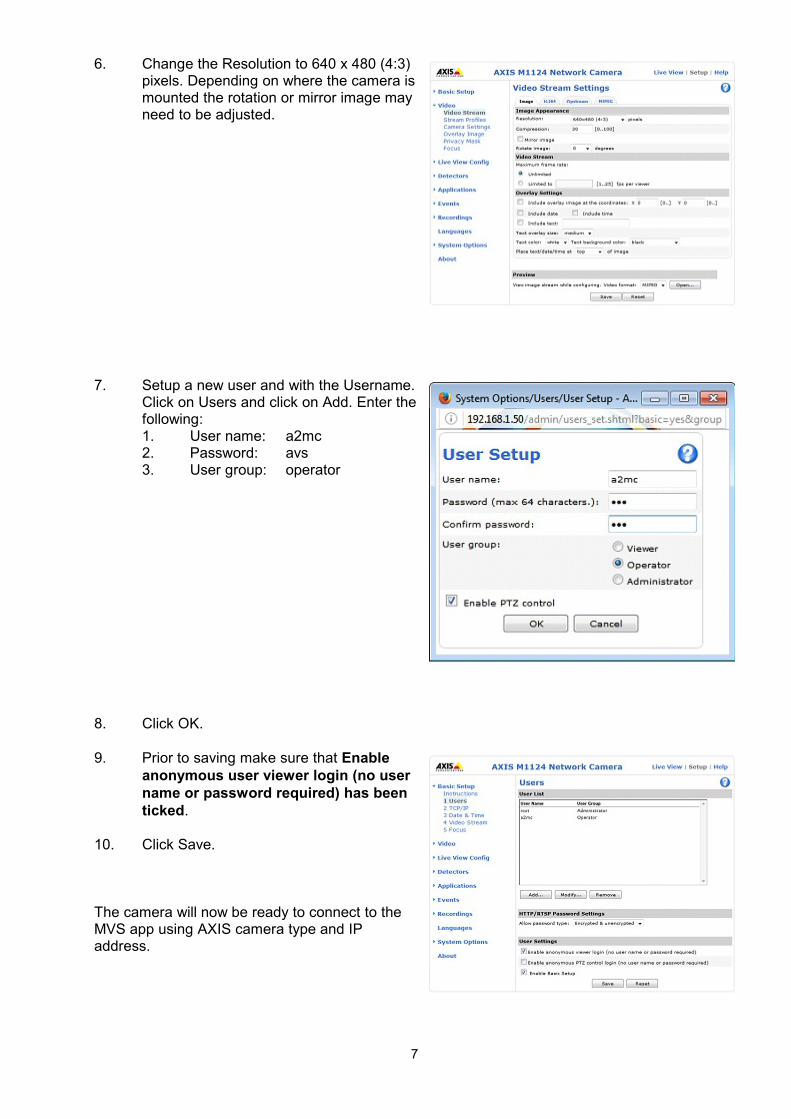
6. Change the Resolution to 640 x 480 (4:3)pixels. Depending on where the camera ismounted the rotation or mirror image mayneed to be adjusted.
7. Setup a new user and with the Username.Click on Users and click on Add. Enter thefollowing:1. User name: a2mc2. Password: avs3. User group: operator
8. Click OK.
9. Prior to saving make sure that Enableanonymous user viewer login (no username or password required) has beenticked.
10. Click Save.
The camera will now be ready to connect to theMVS app using AXIS camera type and IPaddress.
7

Connecting the IP Camera and starting the MVS Application
To use the camera with a machine you must have the MVS Applicationinstalled and running.
The MVS Application is launched from the Application Manager.
Start the Application Manager and then click on the MVS Button to launchthe MVS Application.
Once the MVS Application is loaded, connect to themachine as usual by entering the machine IP address(not the camera IP Address)
Then click on Connect
Choose the camera type, enter the camera IP addressthen click OK.
A preview image will appear in the Vision System app.
Click on the Vision System connect icon to
start the MVS application.
8
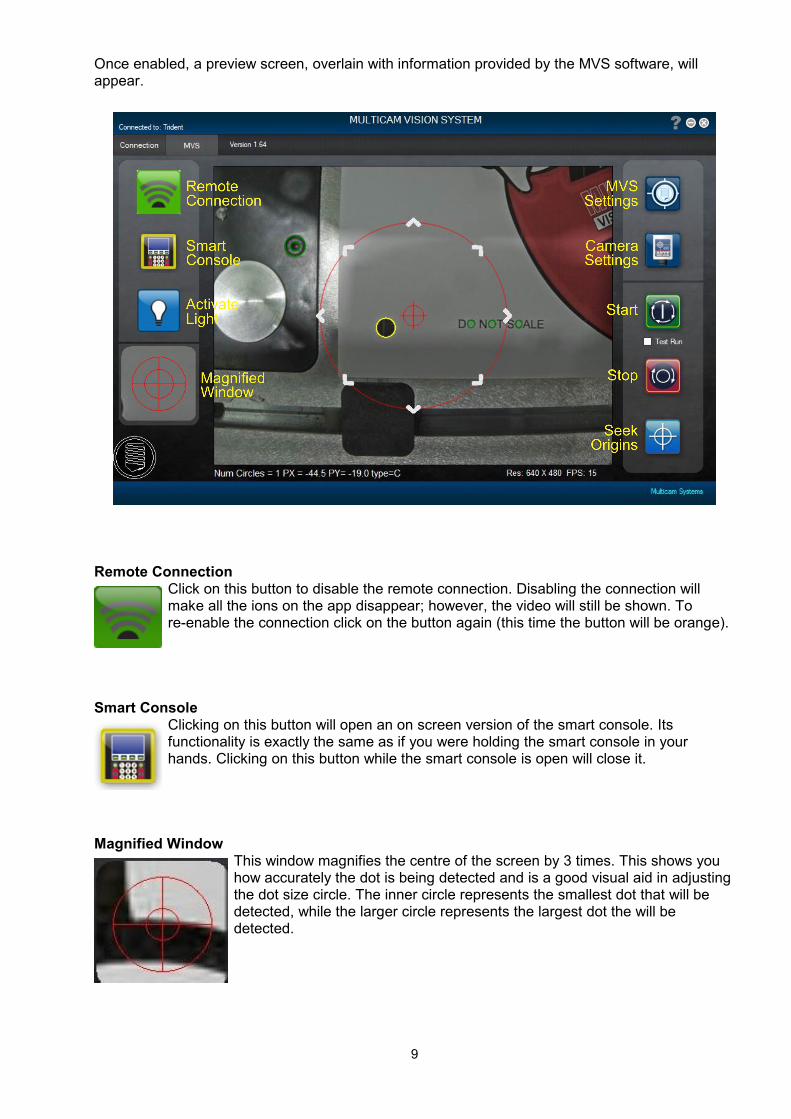
Once enabled, a preview screen, overlain with information provided by the MVS software, willappear.
Remote Connection Click on this button to disable the remote connection. Disabling the connection willmake all the ions on the app disappear; however, the video will still be shown. Tore-enable the connection click on the button again (this time the button will be orange).
Smart Console Clicking on this button will open an on screen version of the smart console. Itsfunctionality is exactly the same as if you were holding the smart console in yourhands. Clicking on this button while the smart console is open will close it.
Magnified WindowThis window magnifies the centre of the screen by 3 times. This shows youhow accurately the dot is being detected and is a good visual aid in adjustingthe dot size circle. The inner circle represents the smallest dot that will bedetected, while the larger circle represents the largest dot the will bedetected.
9
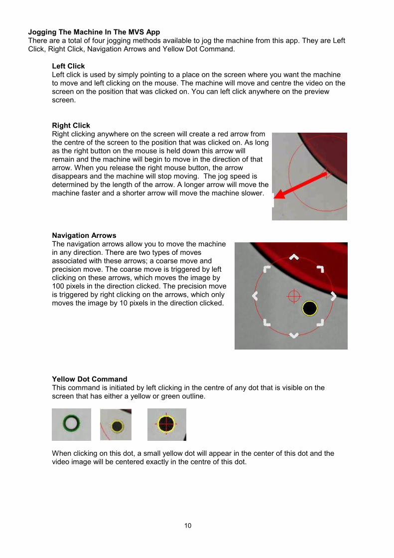
Jogging The Machine In The MVS AppThere are a total of four jogging methods available to jog the machine from this app. They are LeftClick, Right Click, Navigation Arrows and Yellow Dot Command.
Left ClickLeft click is used by simply pointing to a place on the screen where you want the machineto move and left clicking on the mouse. The machine will move and centre the video on thescreen on the position that was clicked on. You can left click anywhere on the previewscreen.
Right ClickRight clicking anywhere on the screen will create a red arrow fromthe centre of the screen to the position that was clicked on. As longas the right button on the mouse is held down this arrow willremain and the machine will begin to move in the direction of thatarrow. When you release the right mouse button, the arrowdisappears and the machine will stop moving. The jog speed isdetermined by the length of the arrow. A longer arrow will move themachine faster and a shorter arrow will move the machine slower.
Navigation ArrowsThe navigation arrows allow you to move the machinein any direction. There are two types of movesassociated with these arrows; a coarse move andprecision move. The coarse move is triggered by leftclicking on these arrows, which moves the image by100 pixels in the direction clicked. The precision moveis triggered by right clicking on the arrows, which onlymoves the image by 10 pixels in the direction clicked.
Yellow Dot CommandThis command is initiated by left clicking in the centre of any dot that is visible on thescreen that has either a yellow or green outline.
When clicking on this dot, a small yellow dot will appear in the center of this dot and thevideo image will be centered exactly in the centre of this dot.
10

MVS SettingsClicking on this button will open the VisionSettings window to allow you to modify thevision settings.Once set, these do not usually need to bechanged, however adjustment may be
made depending on prevailing job conditions.
Dot SizeThis is measured in pixels. Adjust this size to the approximate size of the dots on your jobmedia. Use the magnified window to assist you with setting this size. When setting the dotsize, ensure that there is a dot in the centre of the screen. Adjust the dot size so that theyellow outline is surrounding the outside of the dot.
Auto DiameterThis is also measured in pixels. This is the secondary larger circle that you see on yourscreen. The size of this impacts the performance of the vision system. When the system islooking for dots, any dot found within this radius will be centered automatically. The defaultsetting is set to 200 pixels. Make adjustments that are best suited for your job type.
Camera Off During JobAs the camera is not required when a job is running, you can set this option to disable itonly during a job. When the job is complete, the camera image will re-appear. This featureis useful as sometimes the equipment such as the vacuum pumps, spindles and dustcollectors will interfere with the communication of the camera and cause frequentdisconnects. To avoid the issue of unexpected disconnect, use this feature.
Camera CalibrationThis tells us the resolution of the camera in terms of measurable units. Based on whetheryour system is set to use imperial or metric units, this is measured in pixels per inch(imperial) or pixels per mm (metric). This number will vary based on the height/zoomsetting of the camera, but it is normally around 100 pixels/inch or 4 pixels/mm. This isdetermined automatically through the calibration routine.
Camera AngleAs the camera cannot be installed perfectly square to the X and Y axis, this value willcompensate or that error. This isn’t angle measurement, so it’s measured in degrees.Usually, this number is quite small, between -2 and +2 degrees. This is also automaticallydetermined through the calibration routine.
11
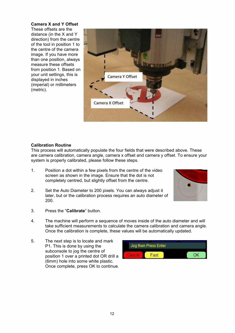
Camera X and Y OffsetThese offsets are thedistance (in the X and Ydirection) from the centreof the tool in position 1 tothe centre of the cameraimage. If you have morethan one position, alwaysmeasure these offsetsfrom position 1. Based onyour unit settings, this isdisplayed in inches(imperial) or millimeters(metric).
Calibration RoutineThis process will automatically populate the four fields that were described above. Theseare camera calibration, camera angle, camera x offset and camera y offset. To ensure yoursystem is properly calibrated, please follow these steps.
1. Position a dot within a few pixels from the centre of the videoscreen as shown in the image. Ensure that the dot is notcompletely centred, but slightly offset from the centre.
2. Set the Auto Diameter to 200 pixels. You can always adjust itlater, but or the calibration process requires an auto diameter of200.
3. Press the “Calibrate” button.
4. The machine will perform a sequence of moves inside of the auto diameter and willtake sufficient measurements to calculate the camera calibration and camera angle.Once the calibration is complete, these values will be automatically updated.
5. The next step is to locate and markP1. This is done by using thesubconsole to jog the centre ofposition 1 over a printed dot OR drill a(6mm) hole into some white plastic.Once complete, press OK to continue.
12

6. Next, the console will prompt to move“Camera to P1 Mark”. Using the JogControls in the MVS software movethe camera image so that the markyou determined in Step 5 is inside theauto diameter circle. Once there, click on the dot/hole and the camera will centreitself over that point and the x and y offsets will be automatically calculated and set.
Note:If you are using an Oscillating knife and camera system it can be difficult to accurately alignthe center of the knife head with the dot as the tip of the blade is often offset. Normalpractice is to use a 6mm blank or dummy shaft that is placed in the knife head instead of ablade. This can then be used to accurately center the knife head in to the drilled hole. Youcan make a simple calibration plate with a 6mm hole in it and keep it for just this purpose.
You should always home the machine after swapping to or re-fitting any heads.
Camera SettingsClicking on this button will open acamera settings window, which will allowyou to adjust various camera settings toget you the best picture. These settingsshould only be adjusted if you find itdifficult to detect the dots. This feature is
only available if you have the Axis Camera, ModelP1354. The image you see will be the one used to findthe dots.
BrightnessThis adjustment changes how bright the image appears on your window. If your image isdark, then increase the brightness, however, if your image appears to be too bright, thendecrease your brightness
ContrastThis setting determines how the camera interprets the difference between dark colours andlight colours. The higher the setting the visual difference between light and dark coloursstarts to increase and the lower the setting, the difference starts to decrease. Normally, ifyour dots are faded/bad quality, you would want to increase your contrast.
SharpnessThis setting changes the quality of the shape seen thorough the camera. The higher thesharpness, the more distinct that shape becomes (sharper lines). Lower the sharpnessreduces this affect. Note the increasing the sharpness may not always cause the shape tobe shown better and it may enhance the noise in the image. Reducing the sharpness willreduce the noise. It depends on the quality of the shape.
13

Color LevelThis setting changes the amount of color saturation, which is how intense each colour isdisplayed. A higher level will result in the most colour saturation while a lower settingreduces this effect. The lower the setting the more black and white your image will appear.
White BalanceThis setting determines how the colours are to be displayed based on the light source.Usually, the camera does a good job when set to “Automatic” but if you are having issues,you can change the white balance to match your type of light source.
RotationThere are two rotation options available, 0 or 180 degrees. This rotates the image shownon the screen by the specified amount. Rotation can be checked by making a move usingthe MVS jogging methods. If a move is made to go left and the image goes right, then therotation needs to be changed. An incorrect rotation is automatically fixed during thecalibration process.
Frame RateThis determines how many frames to software processes per second. The maximumsetting, which is the default setting, is 15 FPS (frames per second). If you are experiencingperformance issues, then you should try lowering your frame rate. However, lowering it toomuch may slow down and significantly affect the accuracy of the MVS.
Show FilterAll the image processing performed by the software is done by using a filter. This filter canbe turned on so that you can see the image that the software is using to detect the dots. Ifyou ever need to make adjustments to any of the camera settings, it is recommended toturn the filter on so you can see the effect the changes are having on the image that isused for processing.
Default Settings This restores the original camera parameters. Note that all your changes will be reset.
14

Start MVSClicking this button will start the search for the dots and calculate anyskews/rotational errors. Clicking this button a second time will start the MVS job. If“Test Run” is selected the job will run without actually lowering the head and withoutactivating any appliances. This feature is very useful for training purposes as well astesting out a job to see if things line up before actually cutting into the material.
Stop MVSThis button stops the current MVS job. Pressing it a second time will abort the job.
Seek OriginClicking this button will open up a dialog box where you will be able to select anorigin (G54-G59) and move the machine to that origin. The window that will appear isshown below.
15

16

Understanding Print and Cut
Print and cut is a two step process:1. An image is printed onto usually a rigid or semi rigid material using a flatbed printer.2. The image is mechanically cut out using a router or knife.
The process starts by creating a graphic using some sort or graphics software. The graphicssoftware can be anything that is compatible with the printer.
The material is loaded on to the flatbed printer and the image from the graphics software isprinted.
The graphics software also exports the cutting outline in either “.ai” or “.dxf” format. The “.ai” or“.dxf” file is then imported into a CAM (computer aided manufacturing) software such as Enroute,ArtCAM, or Vectric.
The CAM software then generates an “.nc” format file that the router table can understand.
Finally the router table runs the nc file and cuts out the printed image for the final product.
17

AlignmentThe challenge of the above process is to accurately align the cut file being run on the router to theimage printed on the material by the flat bed cutter.
This is done by printing a number of dots on the material outside of the image:
The dots should be black and about 10mm in diameter. They should be well spread out.
Note: If you are printing on to a dark or patterned substrate, it is recommended that the dots beprinted on a white backgriund, so there is sufficient contrast between the background colour andthe black dot.
There should be at least three dots with four or five being optimal. The centre of these dots arethen located by the MVS camera, processed by the MVS software which adjusts the cutting file toexactly match the printed image.
Dot TypesThe dots can be all the same but this method has the disadvantage in that it is sometimes difficultto know which dot should be located first and which dot is second. The MVS software canrecognize three different types of dots:
Type A is a “target” and is the first dot the software will search for, type B is a donut or annular ringand is the second dot the software will seek, all the rest of the dots are type C and are simply dots.Generally using Type C dots is the simplest and most reliable approach.
If dot types A and B are used then there must be only one of each in the printed image, all theremaining dots are then type C:
18

This diagram shows a typical printed output from the flatbed printer using one type A, one type B,and two type C dots.
On the actual MVS operator’s screen the different dot types appear as follows:
Note that dot type C is not labeled.
Creating Dot TypesIt is important that the dot types are created properly in your graphics software.
When creating the annular ring or “type B” the wrong way is to create a circle andthen give the outline a thickness as shown on the left. When this gets exported asan outline to the CAM program all you will get is a single circle indicated by theyellow dashes.
The correct method is to put a white dot into the centre of a black dot. Nowyou will get two outlines as shown on the left.
For a “type A” dot, just put a third black dot in the centre to get a third outlineas shown.
19

Importing into CAM SoftwareThe next step is to export the cut outline and the dots to the CAM software. Once imported into theCAM software the file should appear as shown below:
Note that the cut file is now the outline of the file.The type C dots are simply small circles. Type Adot are three concentric circles and type B dots aretwo concentric circles.
Tool Pathing the Cut OutlineThe actual cutting outline is toolpathed using whichever tool is required to cut the material. All thedots must be defined as “drill” points and assigned as tool 1000 (T1000). The MVS systemrecognizes tool 1000 to be a dot that will be searched for by the camera.
The dots must be sequenced first, before any ofcutting contours. It does not matter the order of thedots as the MVS software will find the type A dotfirst, the type B second, and it really doesn’t matterwhat the order of the rest of the dots is. It also willnot matter what the depth of the drill is.
20
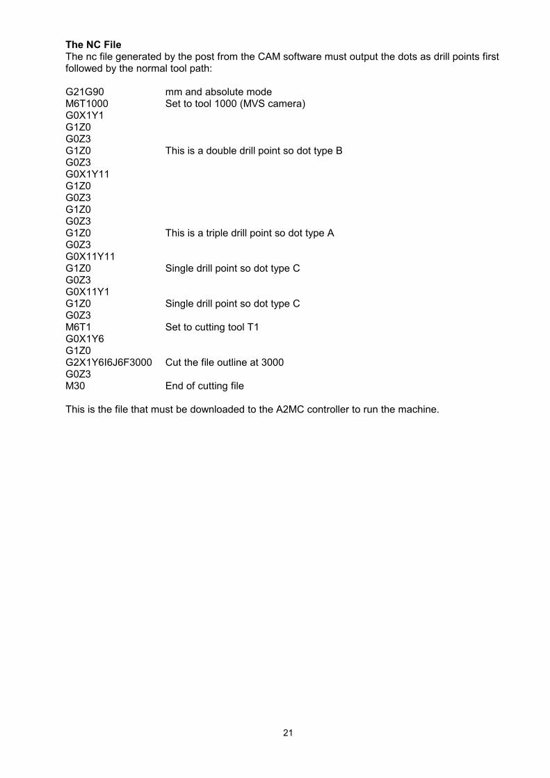
The NC FileThe nc file generated by the post from the CAM software must output the dots as drill points firstfollowed by the normal tool path:
G21G90 mm and absolute modeM6T1000 Set to tool 1000 (MVS camera)G0X1Y1G1Z0G0Z3G1Z0 This is a double drill point so dot type BG0Z3G0X1Y11G1Z0G0Z3G1Z0G0Z3G1Z0 This is a triple drill point so dot type AG0Z3G0X11Y11G1Z0 Single drill point so dot type CG0Z3G0X11Y1G1Z0 Single drill point so dot type CG0Z3M6T1 Set to cutting tool T1G0X1Y6G1Z0G2X1Y6I6J6F3000 Cut the file outline at 3000G0Z3M30 End of cutting file
This is the file that must be downloaded to the A2MC controller to run the machine.
21

Sample File
A sample MVS cut files is available on the A2MC CD or USB so you can test out the MVSApplication:
The folder includes the following files:
1. An “.ai” file that is the entire graphic. This can be opened up in Adobe Illustrator.2. An “.ai” file that contains just the outline of the graphic and the registration dots. This is the
file that can be imported into your CAM package.3. A “.dxf” file that contains just the outline of the graphic and the registration dots. This is the
exact same file as number 2 except in “.dxf” format. Some CAM packages do not do wellwith “.ai” files so this is an alternative.
4. A “.pdf” file of the graphic. This can be used to print your own graphic to try out on themachine. All the graphics are small enough to fit on a normal printer.
5. Finally a “.nc” file which can be downloaded to the machine and run.6. An Enroute ROU file
The quickest way to learn how to use the MVS system is to print the “.pdf” graphics supplied in thesample file and download the associated “.nc” file in the A2MC controller. Once you have thesample “.pdf” and “.nc” files running as you expect simply work backwards through your graphicsand cam software using the attached “.ai” files.
Running GhostbustersThe “Ghostbusters” folder has theMVS files.
Open the pdf file and you should seethe image on the left. Print the imagein either black or white or incolour.
Note the four registration dots on theimage. There is one type A dot at thetop, one type B on the left side andthe lower and right hand ones aretype C.
Lay the printed image on the machinebed.
Download the “ghostbusters.nc” fileinto the A2MC controller.
The first time you run the job youshould put the MVS software into “Test Run” mode by checking the box in the MVS Application.
Test run will simply run the job above the material so you can see what is going on. Once you areready uncheck it and the MVS system will run the full job.
22

The next step is to set the G55 origin of the job close to the lower left corner of the sheet of paperas shown below:
The next step is to set theG55 origin of the job close to the lower left cornerof the sheet of paper.
Use Function 10 on the machine to select G55user origin.
The reason you need to do this is so that thecamera will get close enough to the first dot so thatthe MVS system can find it automatically.
Next, the ghostbusters job needs to be selected. Open up the smart console window on screen orgo directly to the smart console at the machine. Click the folder button on the smart console and browse to the ghostbusters.nc file. Select the fileand press “OK”. This will make ghostbusters the active job.
Once the MVS software has been set to “Test Run”, the origin (G55) set to the lower left corner ofthe material and the ghostbusters.nc file has been made the active job, press the start button torun the job.
The machine will now search for each of the dots in sequence starting with the Type A dot, thenthe Type B dot, and then all the rest. In this job there are four dots in total. Once each dot is found,the machine will centre itself over the dot and move on to the next one.
If the MVS is set to “Test Run” the machine will retrace all the dots and check and report on theaccuracy.
You will see this on the display as well as it is printed out in the activity log:
C 4:44:25 PM Dry run dot testing started...C 4:44:25 PM in stretchy. XSCos= 1.0014 YSSin= -0.0080 YSCos= 0.9997 XSSin= -0.0117C 4:44:25 PM offset X = -5.374 offset Y= -17.577C 4:44:29 PM dot #1 x=0.379 y=-8.049 dx=0.008 dy=0.000C 4:44:34 PM dot #2 x=-3.522 y=-10.217 dx=0.004 dy=-0.004C 4:44:38 PM dot #3 x=-1.529 y=-14.333 dx=-0.004 dy=-0.004C 4:44:42 PM dot #4 x=2.777 y=-12.179 dx=0.004 dy=0.000C 4:44:42 PM ....Dry run dot testing ended.
23

The displacement values, dx and dy, are shown in mm and should be less than 0.01 if everythingis working properly.
Once this is complete, the operator console display will prompt you to start the job by pressing theSTART button again.
The job will run in test run mode with the camera running exactly over the image so you can watchon the computer screen exactly how closely the image is traced out. The only difference when notrunning in “test run” is that the dots are not retraced and the spindle/knife will actually cut on theimage.
If the origin is off by a considerable distance or the image is severely rotated out of place the firstand/or second dot might be significantly out of place and outside the auto circle as shown in theexample above. In this case the operator display will prompt you to locate the correct dot type. Simply jog using the built in vision controls, until the correct dot appears on the screen and click onthe dot. The dot will be centered automatically and the MVS will proceed to find the rest of thedots. After the second dot the MVS system will have calculated the correct origin and rotationadjustment and it should find the rest of the dots without further operator intervention.
To get familiar with the MVS system, use the sample file that is provided and practice rotating andshifting the sample job around on the table.
24

Software Installation - Legacy Vivotek IP7130 camera
Parts required:1 off Vivotek IP7130 camera1 off Vivotek IP7130 installation CD1 off 90 degree mounting bracket1 off GUI 9.002
Installing Vivotek Software and ConfiguringInsert the Vivotek installation CD into your CD-ROM and let it autorun
1. The main window will appear. Click on Software Utilities.
2. The Software window will appear. Click on InstallationWizard 2.
3. The Installation Wizard 2 window will appear. Click onInstallation Wizard 2.
4. The license agreement window will appear. Click on I Agree.
25
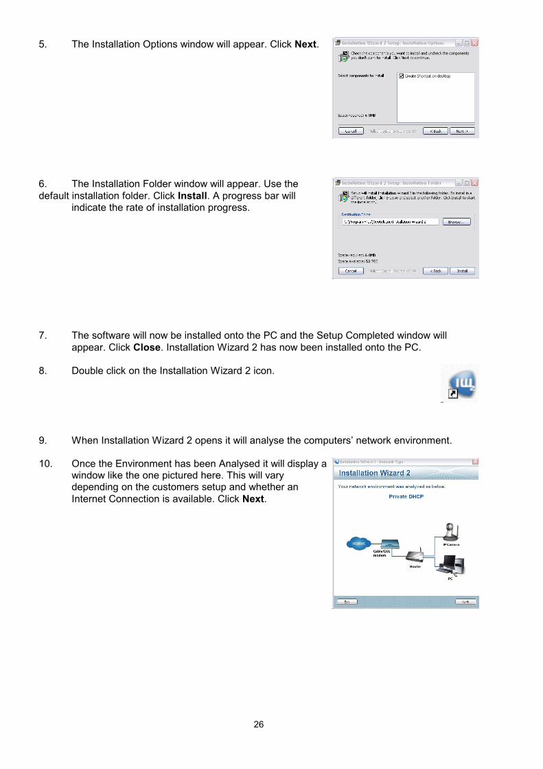
5. The Installation Options window will appear. Click Next.
6. The Installation Folder window will appear. Use thedefault installation folder. Click Install. A progress bar will
indicate the rate of installation progress.
7. The software will now be installed onto the PC and the Setup Completed window willappear. Click Close. Installation Wizard 2 has now been installed onto the PC.
8. Double click on the Installation Wizard 2 icon.
9. When Installation Wizard 2 opens it will analyse the computers’ network environment.
10. Once the Environment has been Analysed it will display awindow like the one pictured here. This will varydepending on the customers setup and whether anInternet Connection is available. Click Next.
26

11. If an Internet connection is not present the window maylook something like this one followed by a window statingthat an Internet connection is not present, but the cameracan still be setup in manual mode. Click OK.
12. Now the Device Selection window will display. Thisshould display the camera that has been installed. It willdisplay the MAC ID for the camera as well as the currentIP address and model. Double click on the device and itwill open in Internet Explorer.
13. This is a sample window of what willdisplay. Using this interface we canchange the configuration of the camerato what we need. The followingconfiguration settings will need to bechanged: Set Static IP address,Camera Orientation, Video Outputtype.
14. Click on Configuration to access thedifferent parameters that can bechanged.
27

15. Click on Advanced mode so that all ofthe parameter options become available.
16. Now the parameters have been set toAdvanced mode we can begin to configure the
camera. To set a static IP address forthe camera click on Network.
17. Once in the Network screen click on UseFixed IP Address.
18. Now Enter the Static IP address that youwish to use. You may also need to enterthe Subnet Mask and Default gateway ifthey have not been detected by thesoftware. Click Save when finished.
28

19. The camera will now reboot and the following message willdisplay. Once it has rebooted it will return to the camerashome page. Click on Configuration to continue the setupprocess.
20. Click on the Audio and Video section.This will display the Audio and Videosettings. As you can see from the videodisplayed in earlier pictures theorientation of the camera needs to bechanged. Click on the Flip and MirroredCheck Boxes to change the orientation.Click Save to accept these changes.
21. To run the camera through the GUI thevideo needs to be changed to JPEG. Todo this click on Video quality settingsfor stream 1. Change the Video typefrom MPEG-4 to JPEG. Set the Framesize to 640 x 480 and set the frame rateto 15 fps. Click Save once theseparameters have been set.
Note: The Contrast and Sharpness of apicture can be altered by clicking thImage settings button.
The Camera will now be setup and ready to use. If further adjustments need to be made they canbe done by either using Installation Wizard 2 and following the direction above or Internet Explorercan be opened and the IP address can be typed in the address bar. Programs like Real Player willalso open the camera using the IP address.
29