multidisciplinary robust design optimization of an ... · multidisciplinary robust design...
TRANSCRIPT
American Institute of Aeronautics and Astronautics
1
Multidisciplinary Robust Design Optimization of an Electric Pump for Dishwashers
Carlo Poloni1, Valentino Pediroda2 Department of Energetics, Trieste, Trieste, 34127, Italy
Mauro Poian3 Esteco s.r.l., Trieste, Trieste, 34012, Italy
Giovanni Creatti4, Fabrizio Sandron5, Massimo Furlan6 Appliances Components Companies, Pordenone, Pordenone, 33170
The paper describes the Robust Design Optimization (RDO) of an Electric Pump for Dishwashers. The aim of this work is to apply RDO techniques to the design of a large scale product and, in particular, the optimization target is to improve the efficiency and lower the cost of the whole system, as well as to fulfil requirements on the overall dimensions and head. Once an optimized geometry which meets all the requirements is obtained it will become a standard pump listed in the company catalogue. The authors gave a particular attention to the numerical model validations and to the theoretical study of the hydraulic and electromechanical coupling. The parametric model representing the main geometrical features of the water pump was created using the commercial CAD tool, Catia v5 and it had some simplifications, compared with the model used for the production water pump but it was considered to be accurate enough to provide a good analysis of the hydraulic performance of the pump. A numerical model of the hydraulic part of the water pump was created using the commercial mesh generator, ICEM CFD and CFX5 was used as Computational Fluid Dynamics (CFD) solver. A Genetic Algorithm (GA) was used for the Robust Design Optimization of the electric water pump and the best configuration was selected using a Multi Criteria Decision Making (MCDM) tool over Pareto frontier designs. In spite of the complexity of the operation necessary for the optimization of the electric motor and hydraulic pump assembly, the optimized electric water pump is more efficient than optimizing just the electric motor, and coupling it with an existing pump. The optimized electric water pump will be validated by experimental tests in the near future.
Nomenclature φ = dimensionless flux ψ = dimensionless mass flow rate ω = angular velocity ρ = density η = efficiency g = acceleration due to gravity H = head D = diameter of the pump rotor Q = mass flow rate P = power 1 Professor, University of Trieste, Via Valerio 10, 34127, Trieste, Italy, [email protected] 2 Dr., University of Trieste, Via Valerio 10, 34127, Trieste, Italy, [email protected] 3 CAE Consltant, ESTECO srl, Padriciano 99, 34012 Trieste, Italy, [email protected] 4 R&D Engineer, R&D Department, Via Consorziale 13, 33170 Pordenone, Italy, [email protected] 5 R&D Engineer, R&D Department, Via Consorziale 13, 33170 Pordenone, Italy, [email protected] 6 R&D Manager, R&D Department, Via Consorziale 13, 33170 Pordenone, Italy, [email protected]
11th AIAA/ISSMO Multidisciplinary Analysis and Optimization Conference6-8 September 2006, Portsmouth, Virginia
AIAA 2006-7097
Copyright © 2006 by the American Institute of Aeronautics and Astronautics, Inc. All rights reserved.
American Institute of Aeronautics and Astronautics
2
I. Introduction The need for ever better performance at an ever lower cost, together with the demand for power consumption
reduction, calls for an increase in standardization and the use of optimization in the household appliance components industry.
This paper describes the study of the coupling between the hydraulic and the electro-mechanical parts of an electric water pump for washing machines. The aim of this work was to optimize the efficiency of the whole system and, at the same time, to optimize the set-up of the electric motor in order to minimize production costs. In particular the overall dimensions and head of the new electric water pump must satisfy customer requirements
The entire optimization process was split into three separate tasks and the activity culminated in the construction of a numerical model of the electric motor and the water pump; the last phase of the project was the analysis and validation of the models, together with the Robust Design Optimization of the entire numerical model.
II. CFD model Validation Prior to starting the first step (the hydraulic optimization of the water pump) the numerical model was validated
by comparing the results of a Computational Fluid Dynamics (CFD) simulation of the pump currently in production with experimental data. A numerical model of the hydraulic part of the water pump was created using the commercial mesh generator, ICEM CFD. The simulated geometry consisted of a simplified pump: a hexahedral mesh was used for the channel between the blades, as well as for the inlet and outlet pipes, while a tetrahedral mesh,
with prismatic extrusion layers at the walls, was used for the volute. The model was analyzed using the commercial CFD software, CFX5, and since the comparison showed a substantial degree of accuracy of the numerical model (see Table 1), the same numerical approach was used for the following optimization phase.
III. Fluid-dynamic optimization of the hydraulic pump The creation of the parametric model representing the main geometrical features of the water pump was the basis
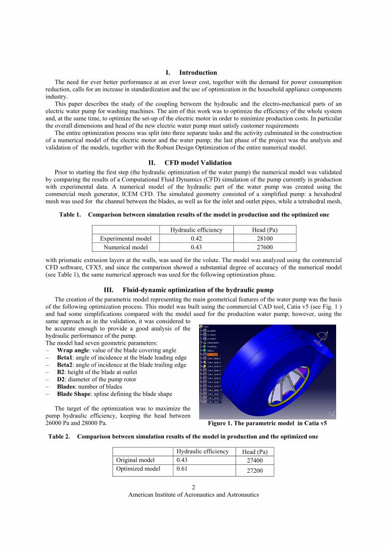
of the following optimization process. This model was built using the commercial CAD tool, Catia v5 (see Fig. 1 ) and had some simplifications compared with the model used for the production water pump; however, using the same approach as in the validation, it was considered to be accurate enough to provide a good analysis of the hydraulic performance of the pump. The model had seven geometric parameters: – Wrap angle: value of the blade covering angle – Beta1: angle of incidence at the blade leading edge – Beta2: angle of incidence at the blade trailing edge – B2: height of the blade at outlet – D2: diameter of the pump rotor – Blades: number of blades – Blade Shape: spline defining the blade shape
The target of the optimization was to maximize the pump hydraulic efficiency, keeping the head between 26000 Pa and 28000 Pa.
Table 1. Comparison between simulation results of the model in production and the optimized one
Hydraulic efficiency Head (Pa) Experimental model 0.42 28100
Numerical model 0.43 27600
Figure 1. The parametric model in Catia v5
Table 2. Comparison between simulation results of the model in production and the optimized one
Hydraulic efficiency Head (Pa) Original model 0.43 27400 Optimized model 0.61 27200

American Institute of Aeronautics and Astronautics
3
The commercial multi-objective optimization software, modeFRONTIER (see Fig. 2), was used to integrate all elements of the analysis process necessary for the evaluation of each design, and to run the optimization process. A Genetic Algorithm (GA) [1,2,3] was chosen to perform the optimization, as there was no knowledge, a priori, of the response of the system; robustness (the ability of the method to reach the absolute extreme of the objective function) was the most relevant factor in the choice of the optimization algorithm.
The GA evolved for eight generations starting from an initial population of fourteen individuals. The optimization ran for 198 hours on a 3 CPU Windows cluster (3.1 GHertz, 2 Gbytes per node); the optimization results are shown in Fig. 3 and Table 2.
The encouraging results obtained from the optimization of the numerical model were validated by constructing
Figure 2. Hydraulic optimization workflow
Figure 3. Optimization history, the squares represent the designs which meet the constraint onhead, while the triangles design represent those which break the constraint

American Institute of Aeronautics and Astronautics
4
and testing a physical prototype, which was built using the best configuration produced by the optimization. Although some small modifications had to be introduced for manufacturing reasons, the geometry was kept as
close as possible to the optimized geometry. The diameter of the rotor was increased slightly in order to ensure that the head would be above the lower limit of 26000 Pa. Table 3 shows the performance of this prototype and of the pump currently in production: Although the efficiency of the prototype is lower than that predicted by the simulation it is still higher than that of the pump currently in production. This difference may be due to the larger rotor diameter, chosen to increase the head.
IV. Coefficient tuning of the electric motor numerical model Coupling the hydraulic pump prototype with the electric motor currently in production, the characteristic curves,
head/mass flow (H-Q) and efficiency/mass flow (η-Q), of the prototype were obtained by experiment, see Fig. 4 and Fig 5. Using the same experimental data the characteristic dimensionless curve of the hydraulic pump was obtained (φ-ψ), see Fig. 6.
The second part of this work involved creating a numerical model of the electric motor and tuning its configuration parameters. The model was built using an electric motor design software; the aim of this step was to tune the empirical coefficients in the electric motor software in order to match test data for this geometry. After tuning, the model could be used, coupled with the hydraulic pump model, for the final optimization. Such coefficient tuning can also be considered an optimization problem where the objective is the minimization of the difference between the numerical model results and the experimental data.
In this case the optimization’s free parameters were twenty-five empirical coefficients in the design and analysis tool, including adjustment factors for rotor yoke flux-density, for stator leakage reactance, for auxiliary winding leakage reactance, etc.
The three objectives of the optimization were the minimization of the standard deviation of the three characteristic curves which represent the electro-mechanical characteristics of the electric motor (torque/speed curve, current in the principal winding/speed, electric power/speed).
Furthermore three constraints were applied (in order to control the current in the auxiliary winding/speed, the iron loss, and the starting torque). As there were multiple objectives, a GA was chosen.
The GA evolved for sixty generations starting from an initial population of one hundred and fifty individuals, created using a Sobol Design of Experiment (DOE) algorithm.
Figure 5. Characteristic curve η-Q for the optimized prototype
Figure 4. Characteristic curve H-Q for the optimized prototype
Table 3. Comparison between results of the physical model currently in production and the optimized prototype
Hydraulic efficiency Head (Pa) Original model 0.42 28000
Optimized model 0.55 31000

American Institute of Aeronautics and Astronautics
5
The optimization ran for 16 hours on a Windows PC (2.4 GHertz, 256 Mbytes); the results are shown in Fig. 7. Over five hundred belonged to the Pareto frontier; from these the best configuration was selected using a Multi Criteria Decision Making (MCDM) [4,5,6] tool.
Looking at the curve in Fig. 8 and Fig. 9 it is evident that the numerical model gives a good approximation of the experimental data in the operating range (2500 to 2850 rpm).
The last part of this work was to optimize the entire electric water pump, that is, the assembly of the hydraulic pump and the electric motor. The aim of the optimization was to improve the efficiency and lower the cost of the whole system, as well as to fulfil requirements on the overall dimensions and head; once an optimized geometry is obtained which meets all the requirements, it will become a standard pump geometry listed in the company. The pump was represented by the hydraulic parametric model in its optimal configuration with the above-mentioned manufacturing-related modifications incorporated. The hydraulic characteristics of this model are shown in Table 3, Fig. 4 and Fig. 5.
The electric motor was represented by the model with the optimal configuration coefficients.
V. Theoretical study of the hydraulic and electromechanical coupling A theoretical study of the hydraulic and electromechanical coupling was necessary to develop an automatic integration of the models. The curve mass flow / head of the hydraulic reference model was used to calculate the dimensionless parameters φ and ψ, where
3DQ
ωϕ = , 22 D
gHω
ψ =
which give the characteristics of the pump geometrically similar to the reference model. Considering a pump similar to the reference pump with rotor diameter (D) and a given value of head (H), the rotational velocity (ω) and the mass flow (Q) at the operating point defined by the coupling of the hydraulic pump with an electric motor depends on the characteristics of the two systems, summarized by hydro-mechanical and electro-mechanical characteristic curves, see Figs. 4,- 9.
Figure 6. Characteristic curve φ-ψ for the optimized prototype
Figure 7. Multi-objective optimization results, ; the x axis represents the standard deviation of the torque, the y axis represents the standard deviation of the current and the bubble diameter is proportional to the standard deviation of the electric power. The arrow shows the design chosen using the MCDM tool

American Institute of Aeronautics and Astronautics
6
Given H and D, it was necessary to know ω to calculate φ. Setting ω to an guessed value, pω , it was possible to obtain a value for the operating point of the new pump, and therefore to calculate the dimensionless parameters ψ
22 DgH
pn ω
ψ =
Using the dimensionless curve of the reference pump, nϕ could be evaluated, as could the mass flow nQ of the new pump, given by
3DQ pnn ωϕ= The power exchanged between the rotor’s blade and the fluid is given by
gHQP nn ρ= The next step was to determine the power requirement of the hydraulic pump to rotate at the imposed velocity. Considering an operating point with φ and ψ equal to nϕ and nψ the value of the rotational velocity refω could be evaluated
2ref
ref DgH
ψω =
and 2refrefref DQ ωϕ=
Knowing refQ at the operating point, the efficiency of the new pump could be determined using the efficiency/mass flow (η-Q) curve, see Fig. 2, and thereby the mechanical power, which was necessary to evaluate performance
ηn
pmP
P =,
This is true if the electric motor moved the pump at the rotational velocity pω (the initial guess). In fact, in a the direct coupling the pump rotational velocity depends on the electric motor’s rotational velocity, which in turn depends on the applied load.
⎪⎩
⎪⎨⎧
=
=
mp
mpm PP
ωω,
The power/speed curve of the electric motor was used to deduce the rotational velocity from the Power pmP , .
If pω and mω were equal, this would mean that the velocity assigned at the beginning of the coupling process was
correct; if the difference between pω and mω had been greater than a certain allowable value, the process would
have been repeated in an iterative fashion until reaching equality ( pω = mω ). Once the rotational velocity of the pump at the equilibrium point of the hydraulic and electromechanical power was determined, all the electromechanical and hydraulic characteristics of the pump at the operating point could be established. For this reason, at equilibrium the mechanical power provided by the electric motor must be equal to the power absorbed by the hydraulic pump, and the pump rotational velocity must be equal to the electric motor rotational velocity.

American Institute of Aeronautics and Astronautics
7
VI. Entire pump optimization Having defined an iterative strategy to evaluate the characteristics of the pump at the operating point, the parameters and targets of the entire pump optimization could be determined. The rotor diameter was the only parameter for the hydraulic part, and it was assumed that once this value was set, the entire geometry of the hydraulic pump could be scaled accordingly. The numerical model of electric motor, whose configuration was characterized by the optimized coefficients, had fourteen parameters (number of coils per pole, turns per coil, start capacitance, etc); in particular the stack length of stator and rotor could only have a discrete number of values. The targets of the optimization were:
− Minimization of the electric motor material cost − Maximization of the electric motor efficiency at the operating point − Maximization of the total efficiency of the assembly at the operating point
In particular the electric motor material cost was the sum of the cost of the electromagnetic steel, the cost of the aluminium for short cut rings and the cost of the windings. Since some free parameters of the optimization had stochastic distributions the output quantities also became stochastic quantities and the objectives were evaluated using the mean value of the outputs. The optimized system had to satisfy the following constraints to fulfil design requirements:
− Mass flow to be kept within a certain range of values − Starting torque less than a fixed value − Tension on the starter capacitor less than a fixed value − Current density in the principal and auxiliary windings less than a fixed value
0
0.1
0.2
0.3
0.4
0.5
0.6
0.7
0 500 1000 1500 2000 2500 3000
Vel [rpm]
η [p
.u.]
Rendimento motore Rendimento modello
00.10.2
0.3
0.4
0.50.6
0.7
0 500 1000 1500 2000 2500 3000
Vel [rpm]
η [p
.u.]
Rendimento A 085 G 25/E Rendimento ottimo
a) b) Figure 9. Comparison between real data and the numerical results; a) Electric Efficiency/Velocity curves for a non-optimized model, b)Electric Efficiency/Velocity curves for the optimized model.
0
50
100
150
200
250
0 500 1000 1500 2000 2500 3000
Vel [rpm]
P [W
]
P elt motore P elt modello
0
50
100
150
200
250
0 500 1000 1500 2000 2500 3000
Vel [rpm]
P [W
]
P elt A 085 G 25/E P elt ottimo
a) b) Figure 8. Comparison between real data and the numerical results; a) Electric Power/Velocity curves for thenon-optimized model, b) Electric Power/Velocity curves for the optimized model.

American Institute of Aeronautics and Astronautics
8
As mentioned earlier, some of the free parameters of the optimization had a stochastic distribution, and therefore the constraints derived from the output quantities were also stochastic.
Also in this case the multi-objective optimization software, modeFRONTIER (see Fig. 10), was used to integrate all elements of the analysis process necessary for the evaluation of each design, and to run the optimization of the assembly. A GA was used for the Robust Design Optimization [7,8,9] of the electric water pump. The GA evolved for twenty generations starting from an initial population of thirty two individuals. Eighteen sampling points were used for the stochastic evaluation of each single nominal configuration. The optimization took 288 hours on a Windows PC (3.1 GHertz, 1 Gbyte); the optimization results are shown in Fig. 11.
Figure 10. Hydraulic optimization workflow
Figure 11. Multi-objective Optimization results, x axis represents the electric motor material cost, y axisrepresents electric motor efficiency, the bubble diameter is proportional to global efficiency of the assembly in the working point. The arrow shows the design chosen using the MCDM tool

American Institute of Aeronautics and Astronautics
9
Over five forty designs belonged to the Pareto frontier from which the best configuration was selected using modeFRONTIER’s Multi Criteria Decision Making tool.
VII. Conclusion Replacing the current electric water pump with the optimized increased the efficiency of the motor at the operating point by 8% The optimized water pump had a total efficiency (the efficiency of the assembly formed by the electric motor and the hydraulic pump) greater than that of the current system (28% against 23%) The cost of the optimized water pump was 15% less than that of the current assembly The work flow used for the final optimization can be extended to more general applications In spite of the complexity of the operation necessary for the optimization of the electric motor and hydraulic pump assembly, the optimized electric water pump is more efficient than optimizing just the electric motor, and coupling it with an existing pump. The optimized electric water pump will be validated by experimental tests in the near future in order to check the optimization results. Given the success of the validation of the component parts in the initial optimizations, it is expected that the test results will again show good agreement with the results of the simulation of the optimized model. Furthermore, these very promising results could be further improved by increasing the number of parameters of the optimization of the electric water pump. Of particular interest would be to consider geometry changes (e.g. stack stator length, etc), as well as the use of different materials.
References 1Goldberg, D. E., Genetic Algorithms in Search, Optimization and machine Learning, Addison-Wesley, Reading,
Massachusetts, 1989. 2Yamamoto, K., Inoue, O., New evolutionary direction operator for genetic algorithms, AIAA Journal, Vol. 33, No 10, pp
1990,1993, 1995. 3Poloni, C., Pediroda, V., “GA coupled with computationally expensive simulations: tools to improve efficiency”, Genetic
Algorithms and Evolution Strategies in Engineering and Computer Science, edited by Duagliarella, D., Periaux, J., Poloni, C., Winter, G. J. Wiley and Sons, New York, 1997, pp 267,288
4Sen, P, Yang, J.B., Multiple Criteria Decision Support in Engineering Design, Springer-Verlag, London, 1998. 5Triantaphyllou, E., Multi-Criteria Decision Making Methods: A Comparative Study, Kluwer Academic Publishers,
Dordrecht, The Netherlands, 2000. 6Yu, P.L., Multiple Criteria Decision Making: Concepts, Techniques and Extension, Plenum Press, New York, 1985. 7Yang, K., EI-Haik, B.S., Design for Six Sigma, McGraw-Hill, New York, 2003. 8Park, S. H., Robust Design and Analysis for Quality Engineering, Chapman & Hall, London, 1996. 9Bagchi, T. P., “Taguchi Methods Explained: Practical Steps to Robust Design”, Prentice Hall of India, New Delhi, 1993.