multihop energy efficient reliable and fault tolerant routing
TRANSCRIPT

International Journal of Emerging Technology and Advanced Engineering
Website: www.ijetae.com (ISSN 2250-2459, ISO 9001:2008 Certified Journal, Volume 3, Issue 2, February 2013)
395
Multihop Energy Efficient Reliable and Fault Tolerant
Routing Protocol for Wireless
Sensor Networks K. Vinoth Kumar
1, S.Karthikeyan
2
1Assistant Professor, M.A.R College of Engg&Tech, Viralimalai, Tamil Nadu. 2PG Scholar, Karpagam University, Coimbatore, Tamil Nadu.
Abstract--The work in this paper aims at designing
a multihop energy efficient, reliable and fault
tolerant routing protocol. It proposes to maintain an
asymmetric network of sensors so that the nodes get a
chance to configure their transmission ranges best,
and thus delivers data to the base station using as
little energy as possible. Our protocol design
concentrates on the load sharing feature by
maintaining multiple routes and selecting the best one
for relaying the data packets. It assigns different
transmission powers to different nodes based on the
network topology. The problem of bottleneck around
the base station is addressed by varying the
transmission ranges of the nodes periodically, which
changes the topology, to balance the responsibility
among the nodes across the network.
Index Terms— multihop energy efficient, reliable
and fault tolerant routing, multiple routes,
bottleneck.
I. INTRODUCTION
The work reported in this thesis aims at designing
of a multihop energy efficient, reliable and fault-tolerant
routing protocol. In a fully connected network, all nodes
can directly access the base station. However, wireless
being a broadcast medium, the congestion [1] in such a
network is very high. Typically, each node in a multihop
WSN would discover a path to the base station and route
its data through this path. This causes the nodes near the
base station to be used more frequently than the nodes
away from the base station. The reason is the former set
of nodes not only send their own sensed data, but are
also responsible for forwarding the packets from the far
off nodes in the network. This results in a bottleneck
around the base station. If the nodes around the base
station go dead, then the nodes away from base station
will be unable to send the data unless they increase their
transmission ranges. Figure Fig 1 shows an example of a
typical sensor network. The filled black node is the base
station. The lines depict the connectivity and the filled
gray nodes are the normal sensing nodes.
In this example node-2 and node-3 are one hop
nodes. Node-2 is responsible not only for sending its
own data but also for forwarding the data from nodes-4,
5, 6, 9 and 10. Similarly, node-3 is responsible for
sending its own data and as well as forwarding data of
nodes-7, 8, 11 and 12.
Thus the nodes situated at a distance of one hop from
base station are used more often than the other nodes. It
causes such nodes to dissipate energy at a substantially
higher rate than the rest of the nodes in the network [3].
Consequently, the network becomes dead very soon. The
residual energy in the nodes near the base station may be
sufficient to sense, but may not be sufficient
communicate the sensed data to the base station. This
observation led us to think how a routing protocol may
avoid the formation of transmission bottleneck around
the base station.
Fig-1. Example of a typical sensor network
The underlying idea is to ensure that the energy
dissipation at each node is more or less same over the
entire network. The approach we devised is to adjust
transmission range of individual nodes to provide
connectivity of base station without involving the nodes
near the base station as and when desired. It led to
dynamicity in the sensor network environment.

International Journal of Emerging Technology and Advanced Engineering
Website: www.ijetae.com (ISSN 2250-2459, ISO 9001:2008 Certified Journal, Volume 3, Issue 2, February 2013)
396
We can view the dynamicity as insertion of new
nodes and deletion of nodes (node failure) at random
time. Our second observation is that WSNs experience
high packet losses. So, reliability is also important for
WSN [2]. Transmission reliability can be achieved
through an acknowledgment based protocol. It helps in
deciding the requirement of retransmissions if the packet
loss occurs and thus increases the reliability. An usual
trend in protocol design suggests that the location
parameters play crucial role for the routing purposes.
The determination of position parameters requires use of
embedded GPS receivers. But with embedded GPS
receivers will make the sensor nodes substantially
expensive. Additionally, also the nodes will consume
more power. Therefore, our aim is also to ensure come
up with routing protocols which avoids use of location
based information.
1.1. Problem statement and the Challenges Involved
The investigation in this paper is oriented towards
the design a multi hop routing protocol for time driven
WSN which achieves following objectives.
Avoid the formation of the congestion bottleneck
around the base station
Handle dynamic changes in topology caused by
transmission power adjustments.
Handle node failures on existing paths by a novel
route repair procedure that leverages ability to
adjust node transmission range.
Ensure reliability through use of
acknowledgements and limited retransmission of
lost packets.
Improve the network lifetime by considering
residual node energy during route discovery.
Analyze and compare the new protocol with the
existing ones.
The objectives listed at items 1 and 5 are achieved by
better utilization of the resources and treating the
network as a dynamically changing asymmetric network.
The topology change in the network is mainly
determined by adjustment of transmission range from
time to time. The resulting change topology modifies
path from every node to base station. The routing
protocol is, therefore, is a mix of both proactive and
reactive protocol [4]. The tasks of route discovery and
route maintenance become more challenging in an
asymmetric network, as Hello messages can not be used
for such purposes in asymmetric links. The latency of
route discovery also has to be minimized. Balancing
distribution of load for routing (forwarding packets)
among the nodes shall ensure the uniform and better
resource utilization. The concept of asymmetric network
shall allow the nodes to use appropriate transmission
ranges, which is more suitable for its longer lifetime
depending on its position in the network.
The fault tolerance in routing protocols for WSN is a
novel idea. It has been possible to tolerate node failure
simply by eliminating failed nodes through a route
maintenance step. It involves the adjustment of
transmission power at some nodes for establishing
connectivity with the base station when the routes are
found to be broken due to node failures. We
experimented with up to 5% node failures [5] [6] . The
objective concerning reliability in transmission is
achieved by acknowledgments for the data packets. The
protocol supports at most three retransmissions of the
data packets to handle packet loss. The routing metric is
chosen by optimizing both latency of routes and residual
energies at the nodes. The other desirable property of a
protocol which is addressed is load sharing. The load for
routing data packets is distributed over the multiple
alternate paths available at a node. It ensures overall
better utilization of energy resources and effectively
extends lifetime of the network.
Finally, we performed simulation over OMNet++
261] and compared our results with other notable time
driven WSN routing protocols such as LEACH [14] and
SPIN [13]. Our results show performance enhancement
over symmetric routing protocols and over both SPIN
and LEACH even without data aggregation
II. RELATED WORKS
This chapter deals with related work and the
underlying concepts which form the basis of energy
aware routing protocols for WSN Section 2.1 explains
how simple routing ideas could lead to unnecessary
wastage of precious energy resources. Section 2.2 deals
with some initial thinking done by researchers on the
ways to avoid broadcast storm which appear to be the
main reason behind excessive energy wastage in
routings ideas based on flooding and gossiping. Section
2.3 describes a number of routing protocols, namely,
LEACH [14], PEGASIS [15] TEEN [17] and APTEEN
[16] which try to eliminate redundant data broadcast and
conserve the crucial energy resource by aggregation in
some way or other. Later, section 2.4 which are relevant
in context to this paper. The subject of discussion in
section 2.5 is the quality and reliability of data delivered
by the sensors.
2.1 Flooding and Gossiping
The conventional mechanism for relaying data from
individual sensors to base station is Flooding or
Gossiping. The underlying idea of flooding is that each
sensor on receiving a data packet broadcasts the same to
its every neighbor. This packet is further re-broadcast
until it arrives at the destination or the maximum
number of hops for the packet is reached. Quite
obviously, flooding raises unmanageable broadcast
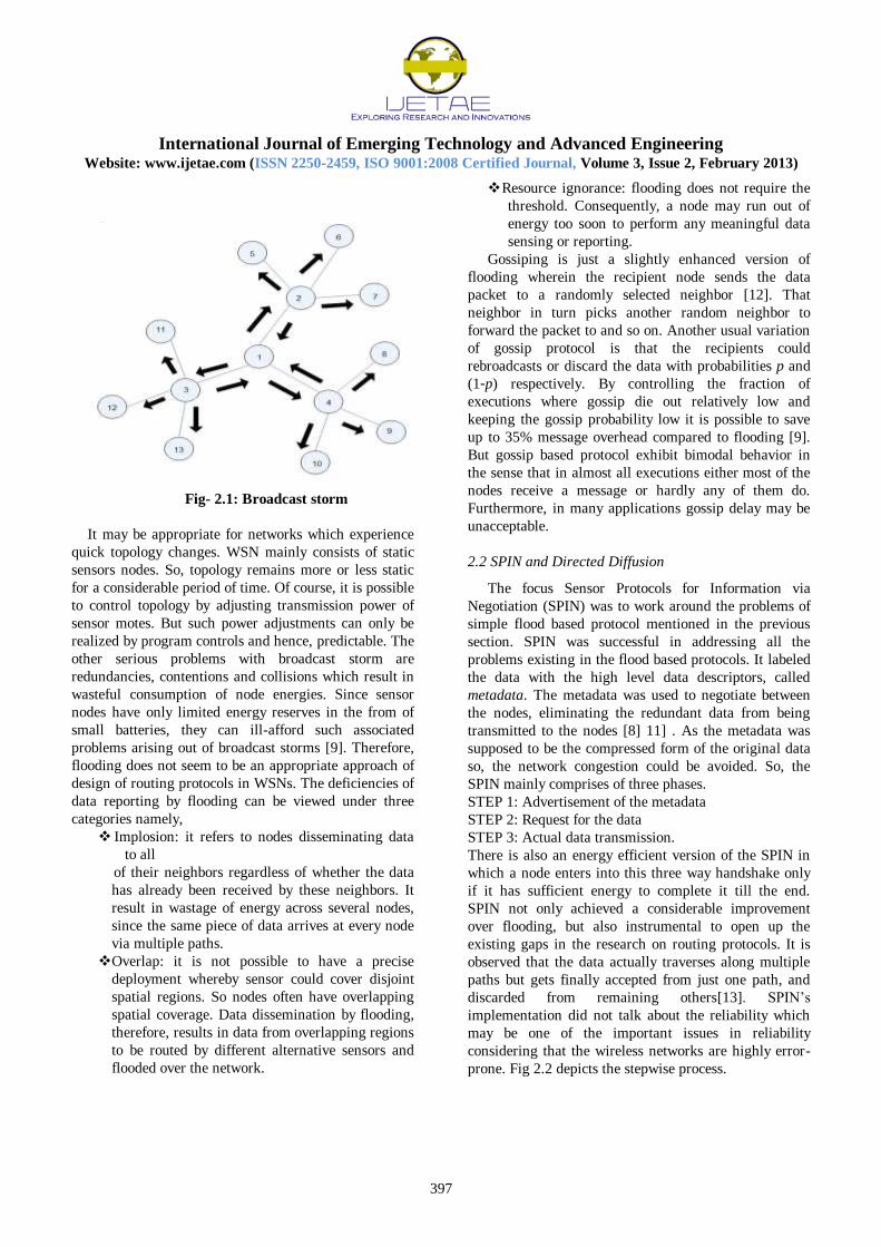
storms as depicted in Fig 2.1.
International Journal of Emerging Technology and Advanced Engineering
Website: www.ijetae.com (ISSN 2250-2459, ISO 9001:2008 Certified Journal, Volume 3, Issue 2, February 2013)
397
Fig- 2.1: Broadcast storm
It may be appropriate for networks which experience
quick topology changes. WSN mainly consists of static
sensors nodes. So, topology remains more or less static
for a considerable period of time. Of course, it is possible
to control topology by adjusting transmission power of
sensor motes. But such power adjustments can only be
realized by program controls and hence, predictable. The
other serious problems with broadcast storm are
redundancies, contentions and collisions which result in
wasteful consumption of node energies. Since sensor
nodes have only limited energy reserves in the from of
small batteries, they can ill-afford such associated
problems arising out of broadcast storms [9]. Therefore,
flooding does not seem to be an appropriate approach of
design of routing protocols in WSNs. The deficiencies of
data reporting by flooding can be viewed under three
categories namely,
Implosion: it refers to nodes disseminating data
to all
of their neighbors regardless of whether the data
has already been received by these neighbors. It
result in wastage of energy across several nodes,
since the same piece of data arrives at every node
via multiple paths.
Overlap: it is not possible to have a precise
deployment whereby sensor could cover disjoint
spatial regions. So nodes often have overlapping
spatial coverage. Data dissemination by flooding,
therefore, results in data from overlapping regions
to be routed by different alternative sensors and
flooded over the network.
Resource ignorance: flooding does not require the
threshold. Consequently, a node may run out of
energy too soon to perform any meaningful data
sensing or reporting.
Gossiping is just a slightly enhanced version of
flooding wherein the recipient node sends the data
packet to a randomly selected neighbor [12]. That
neighbor in turn picks another random neighbor to
forward the packet to and so on. Another usual variation
of gossip protocol is that the recipients could
rebroadcasts or discard the data with probabilities p and
(1-p) respectively. By controlling the fraction of
executions where gossip die out relatively low and
keeping the gossip probability low it is possible to save
up to 35% message overhead compared to flooding [9].
But gossip based protocol exhibit bimodal behavior in
the sense that in almost all executions either most of the
nodes receive a message or hardly any of them do.
Furthermore, in many applications gossip delay may be
unacceptable.
2.2 SPIN and Directed Diffusion
The focus Sensor Protocols for Information via
Negotiation (SPIN) was to work around the problems of
simple flood based protocol mentioned in the previous
section. SPIN was successful in addressing all the
problems existing in the flood based protocols. It labeled
the data with the high level data descriptors, called
metadata. The metadata was used to negotiate between
the nodes, eliminating the redundant data from being
transmitted to the nodes [8] 11] . As the metadata was
supposed to be the compressed form of the original data
so, the network congestion could be avoided. So, the
SPIN mainly comprises of three phases.
STEP 1: Advertisement of the metadata
STEP 2: Request for the data
STEP 3: Actual data transmission.
There is also an energy efficient version of the SPIN in
which a node enters into this three way handshake only
if it has sufficient energy to complete it till the end.
SPIN not only achieved a considerable improvement
over flooding, but also instrumental to open up the
existing gaps in the research on routing protocols. It is
observed that the data actually traverses along multiple
paths but gets finally accepted from just one path, and
discarded from remaining others[13]. SPIN’s
implementation did not talk about the reliability which
may be one of the important issues in reliability
considering that the wireless networks are highly error-
prone. Fig 2.2 depicts the stepwise process.

International Journal of Emerging Technology and Advanced Engineering
Website: www.ijetae.com (ISSN 2250-2459, ISO 9001:2008 Certified Journal, Volume 3, Issue 2, February 2013)
398
Fig-2.2. SPIN
Subsequently, a new protocol called Directed
Diffusion was proposed for event driven applications.
Directed diffusion concentrated on reducing the number
of multiple paths along which data traverses. It also
incorporates some novel features - data-centric
dissemination, reinforcement based adaptation to the
best path, in-network data aggregation, and caching. A
central controller called Sink injects its interest in the
network by normal flooding with a large update
interval. Sensors report data if they match with the
interest received from the sink node. A sensor sends to
the interested node through multiple paths. The
neighboring node establishes a gradient towards each
other based on the direction from which they have
received interest[7] [10]. This way the interested data
finds its path to the sink. Apart from being unsuitable
for continuous data delivery, it incurs extra overhead for
data matching and interest injection.
2.3 Aggregation Protocols
Considering that the sensors are resource constraint,
and the existing inherent redundancies which
characterizes data reporting in SPIN as well as directed
diffusion, a lot of scope for improvements were there.
LEACH is another protocol in line to throw some light
on the same issues and propose some more
improvements. The basic idea employed in LEACH is
cut down the overhead by reduce volume of data
reportage. LEACH[14] is an energy efficient,
aggregation protocol. It includes cluster formation and
local processing to reduce global communication by
collecting the packets of all the nodes in the cluster in
one place and aggregating the information contained.
The randomized rotation of the cluster-heads helps in
implementing the load sharing property. The LEACH
protocol involves the following steps:
STEP 1: Status collection of all nodes by the base
station.
STEP 2: Selection of the cluster heads by the base
station.
STEP 3: Choosing of the best cluster head by the node
STEP 4: Data dissemination to the cluster head
STEP 5: Aggregated data dissemination to the base
station by the cluster heads.
The problem with LEACH is that it considers all the
nodes to have accessibility to the base station when it
becomes the cluster head or when sending the status
message to the base station. According to the MICAz
specifications, the maximum outdoor transmission range
which is allowed for a node is 100m. The indoor
transmission range is even less, it is 30m at the
maximum. That means, to provide one hop connectivity
the maximum distance of a node from the base station
can be at most 100m. If the base station is placed at edge
of the network area then the maximum area which can
be allowed in LEACH. In LEACH each node decides its
cluster head based on which of the heads is closest to it.
It means that the location parameter plays an important
role here. The nodes need to know the position
coordinates of all the cluster heads chosen for that
round. LEACH needs GPS enabled node, which requires
considerable amount of energy apart from making the
sensor motes quite expensive.
The original LEACH proposal provisions for 5% of the
total nodes to be selected as the cluster head. With 100
nodes, the number of clusters formed will be 5. Given
that the maximum area which can be covered is 785m2.
Therefore, even after using so many nodes in such a
small area, the actual data transferred to the base station
is not much. If the volume of data to be transferred to the
control-center is considerable then either the number of
nodes must be increased or the percentage of the total
nodes selected as the cluster heads should be increased.
The energy dissipation at nodes is proportional to the
square of the distance from the destination, therefore,
the node which dies first is always the farthest nodes.
LEACH is not an acknowledgement based protocol. So,
the nodes receive no information of data being lost or
corrupted on the way to the destination. The protocol,
therefore, lacks reliability. The wireless networks are full
of noisy interferences and LEACH does allow any
redundancy in data, as the aggregation removes
redundancy, so non-reliable nature can be considered as
one of the major drawbacks.

International Journal of Emerging Technology and Advanced Engineering
Website: www.ijetae.com (ISSN 2250-2459, ISO 9001:2008 Certified Journal, Volume 3, Issue 2, February 2013)
399
Although the LEACH does not talks directly about
asymmetric links, nor does introduce the concept, it is
implicit from the explanation that the nodes adjust their
transmission range every time they need to
communicate, based on their distance from the node
with which they want to communicate[19] [20]. In a
sense, the network can be considered to be asymmetric.
The asymmetric nature of the network here does help in
avoiding the wastage of energy and congestion, but as
the protocol is not implemented in a distributed way, the
asymmetric characteristic is under emphasized. Rather it
is considered a network with nodes having adjustable
transmission range. Environmental energy harvesting
has also been considered for improving the sustainable
lifetime of the resource constraint network. Numerous
harvesting modalities have been suggested including
solar, vibrational, biochemical, and light. A successful
demonstration of the solar energy. The SOLAR-aware
LEACH aims at extending the lifetime of the sensor
network by choosing solar-aware nodes as the preferable
cluster heads. While the harvesting energy provides the
ability to extract energy from the environment, it must
be efficiently integrated into an embedded system to
translate that harvested energy into increased application
performance and the system lifetime. This shows that
harvesting itself is very complex. The other drawback
being that the solar energy harvesting requires outdoor
system deployment, thus does not work for the indoor
networks.
Lindsay and Raghavan [19] proposed Power Efficient
Gathering in Sensor Information Systems (PEGASIS)
which achieved about 100-300% improvement over
LEACH over a range of percentages of nodes dying out
in different network sizes. In PEGASIS sensor nodes
form a chain to transmit and receive the data. Each node
transmits or receives data from a neighbor and only one
node from the chain is selected to send the data to the
base station. Each node on receiving the data aggregates
it to its own data and then transmits further. The
aggregated data is eventually sent to the base station.
The chain construction is done in a greedy way. Fig 2.3
illustrates that node-0 transmits data to node-1. Node-1
aggregates it to its own data and transmits it to the node-
2. Similarly, node-4 transmits its data to node-3. Node-3
aggregates it to its own data and transmits it to the node-
2. The node to finally aggregates all the received data
along with its own and relays it to the base station.
Fig-2.3: PEGASIS
Unlike LEACH, PEGASIS uses multihop routing and
only one node sends the data to the base station.
Although, PEGASIS shows 100--300% improvement
over LEACH for different network and topologies, there
are many issues which cannot be neglected when
analyzing a protocol. There is only one packet which is
reported to the base station every second, no matter how
large a network may be. The nodes are supposed to be
power adjustable do that if they are eventually selected to
the send the final packet to the base station, then many
must be able to do it in one hop. This again brings to us
the constraint of maximum power which a node can
possess [22]. Given that the maximum outdoor range is
100m, restricts the area which can be covered by
PEGASIS. As PEGASIS reduces the redundancy to zero
in the network, there is expected to be some scheme to
ensure reliability which is again absent.
Threshold sensitive Energy Efficient sensor Network
(TEEN) proposed by Manjeshwar and Agrawal is
actually the modified version of LEACH [14]. The
modification proposed was to convey two attributes to
the nodes from the cluster heads, namely, (i) Hard
Threshold and (ii) Soft Threshold. Hard threshold was
the absolute value of the sensed parameter beyond which
the value must be transmitted to the cluster head. Soft
threshold was the value of the sensed parameter beyond
which the node must activate its transmitter. As the data
was expected to be transmitted less frequently than being
sensed, so the protocol is much more energy efficient
then LEACH. But there are drawbacks which cannot be
neglected. If the threshold is not reached then data is not
communicated to the base station[23] [24]. There were
no messages to inform the base station that whether the
node has gone dead or the data is not crucial enough to
be reported. Thus, the reliability of data reportage
becomes an important drawback. Adaptive Periodic
Threshold sensitive Energy Efficient sensor Network
APTEEN was designed to remove the drawbacks of
TEEN. APTEEN adds an extra attribute to the packet
sent by the cluster heads to the cluster members.

International Journal of Emerging Technology and Advanced Engineering
Website: www.ijetae.com (ISSN 2250-2459, ISO 9001:2008 Certified Journal, Volume 3, Issue 2, February 2013)
400
It not only includes the thresholds but also includes the
maximum interval between two packets. This
modification makes the protocol usable even by time
driven networks.
III. PROPOSED SYSTEMS
Wireless Sensor Networks (WSNs) like mobile
adhoc Networks (MANETs), are self-configuring
networks. But unlike MANETs, they are statically
deployed and each WSN has a central authority, known
as base station. Each sensor performs the sensing task
independent of others, but the routing of the sensed data
to the base station needs communication among the
nodes. Sensor nodes do not communicate except for
forwarding data to the base station or helping in
disseminating data from the base station. Therefore,
when determining the routes in a WSN, single
destination shortest paths is needed. Sensing requires
very little energy as compared to communication
Typically, the major physical layer property which is
assumed to be fixed in design of a routing protocol for
WSNs is the node transmission power. The network with
nodes having uniformly fixed transmission power are
referred to a symmetric networks. The traditional
protocol stack independently models the physical layer
and the higher layers. The abstraction of one layer is
added to the other layer to provide power of multi-
layering. Power control is very important in designing of
any protocol for wireless sensor networks as the nodes
are battery dependent. To control the energy
consumption at the nodes, the transmission range could
be varied. But, the variation should be done considering
the fact that the nodes have at least one path to the base
station and at the same time do not increase their
respective transmission ranges so as to give rise to a
densely connected graph. The configuration of the
physical layer properties at the startup time needs
hardware instructions. The transmission range is
adjusted thereby to get the best results at the network
layer.
When working with asymmetric networks the
physical layer properties come into picture very often, as
transmission range is required to be adjusted from time
to time. The current chapter of this thesis deals with a
proposal for a new routing protocol based on the above
principle of cross layer optimization. Extensive
simulations were carried out to compare the proposed
protocol with some existing protocols. The simulated
protocols include SPIN, LEACH and the two versions of
symmetric protocols. The symmetric protocol versions
are based on DSDV, so minimum hop count has been
used as routing metric.
3.1 Energy-aware Protocols
The research on energy-aware protocols for WSN has
so far focused on two major strategies to optimize energy
usage, viz., (i) reducing transmission of redundant data,
and (ii) confining communication to local sub-regions
(clusters) by partitioning areas of sensing environment.
Two well known protocols, namely SPIN and LEACH
which we chose to simulate are the representative cases
of the above two strategies. We also simulated two
versions of symmetric protocols. The characteristics of
symmetric protocol versions are as follows:
The basic protocol is a modification over
Destination Sequenced Distance Vector
(DSDV) protocol for adhoc networks. The
routing metric used is minimum hop count. The
routing in the first version does not have any
energy optimization criterion.
The second version attempts to make the first
version energy efficient by introducing residual
energy consideration.
The newly proposed asymmetric routing protocol has
been simulated with the purpose of comparing it with
the existing work. We looked at the following three
versions of the proposed protocol.
The first version is just a simple (no energy
consideration) routing protocol that works. for
asymmetric network. It uses minimum hop count
as the routing metric
The second version proposes to make the above
protocol energy efficient by introducing the
consideration of residual energy while relaying
the data.
The third version is adds an aggregation protocol
to combine residual energy consideration with
the idea of confining communication among
nodes locally.
3.2 Routing Protocols for Symmetric Networks
Since, WSNs are resource constraint, the most
important thing to be kept in view when designing a
routing protocol for WSN is that it should be (i) resource
aware, and (ii) should not be too complex to implement.
The symmetric routing protocol has been designed with
these two constraints in mind. The underlying idea is to
avoid flooding or injecting redundant data packets while
the data is being transmitted, a route discovery is
initiated or a route maintenance event occurs.
3.2.1 Multichip Minimum Hop count Protocol
Our first attempt is to find the shortest path between the
nodes and the base station and to be able to maintain it
in a distributed way. We have employed
acknowledgements for the data packets to ensure data
transmission reliable.
International Journal of Emerging Technology and Advanced Engineering
Website: www.ijetae.com (ISSN 2250-2459, ISO 9001:2008 Certified Journal, Volume 3, Issue 2, February 2013)
401
Route Discovery
Normally, route discovery in symmetric networks is
performed in top-down fashion. The base station
initiates a route discovery process by sending a broadcast
message to all the neighbor nodes. Each node caches a
routing table which contains the preferred neighbor and
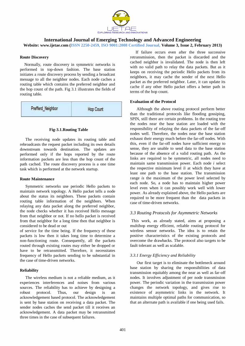
the hop count of the path. Fig 3.1 illustrates the fields of
routing table.
Fig-3.1.Routing Table
The receiving node updates its routing table and
rebroadcasts the request packet including its own details
downstream towards destination. The updates are
performed only if the hops reported by the route
information packets are less than the hop count of the
path cached. The route discovery process is a one time
task which is performed at the network startup.
Route Maintenance
Symmetric networks use periodic Hello packets to
maintain network topology. A Hello packet tells a node
about the status its neighbors. These packets contain
routing table information of the neighbors. When
relaying any data packet along the preferred neighbor,
the node checks whether it has received Hello message
from that neighbor or not. If no hello packet is received
from that neighbor for a long time then that neighbor is
considered to be dead or out
of service for the time being. If the frequency of these
packets is low then it takes long time to determine a
non-functioning route. Consequently, all the packets
routed through existing routes may either be dropped or
have to be retransmitted. Therefore, it necessitates
frequency of Hello packets sending to be substantial in
the case of time-driven networks.
Reliability
The wireless medium is not a reliable medium, as it
experiences interferences and noises from various
sources. The reliability has to achieve by designing a
robust protocol. Thus, our design is an
acknowledgement based protocol. The acknowledgement
is sent by base station on receiving a data packet. The
sender nodes caches the send packet till it receives an
acknowledgement. A data packet may be retransmitted
three times in the case of subsequent failures.
If failure occurs even after the three successive
retransmission, then the packet is discarded and the
cached neighbor is invalidated. The node is then left
with no valid path to relay the data packets. But as it
keeps on receiving the periodic Hello packets from its
neighbors, it may cache the sender of the next Hello
packet as the preferred neighbor. Later, it can update its
cache if any other Hello packet offers a better path in
terms of the hop count.
Evaluation of the Protocol
Although the above routing protocol perform better
than the traditional protocols like flooding gossiping,
SPIN, still there are certain problems. In the routing tree
the nodes near the base station are loaded with the
responsibility of relaying the data packets of the far-off
nodes well. Therefore, the nodes near the base station
exhaust their energy much before the far-off nodes. With
this, even if the far-off nodes have sufficient energy to
sense, they are unable to send data to the base station
because of the absence of a valid routing path. As the
links are required to be symmetric, all nodes need to
maintain same transmission power. Each node i select
the respective minimum level li at which they have at
least one path to the base station. The transmission
range is the maximum of the power level selected by
each node. So, a node has to maintain higher power
level even when it can possibly work well with lower
power. As already explained above, the Hello packets are
required to be more frequent than the data packets in
case of time-driven networks.
3.3 Routing Protocols for Asymmetric Networks
This work, as already stated, aims at proposing a
multihop energy efficient, reliable routing protocol for
wireless sensor networks. The idea is to retain the
positive characteristics of the existing protocols and
overcome the drawbacks. The protocol also targets to be
fault tolerant as well as scalable.
3.3.1 Energy Efficiency and Reliability
Our first target is to eliminate the bottleneck around
base station by sharing the responsibilities of data
transmission equitably among the near as well as far-off
nodes. It involves adjustment of per node transmission
power. The periodic variation in the transmission power
changes the network topology, and gives rise to
existence of asymmetric links in the network. It
maintains multiple optimal paths for communication, so
that an alternate path is available if one being used fails.

International Journal of Emerging Technology and Advanced Engineering
Website: www.ijetae.com (ISSN 2250-2459, ISO 9001:2008 Certified Journal, Volume 3, Issue 2, February 2013)
402
Maintaining Discrete Levels
Our protocol maintains discrete levels of the
transmission range. The transmission ranges changes in
steps. Fig 3.3 depicts the changes in network topology
when the transmission range of the nodes changes in
step of 5. It may be observed that by adjusting node
transmission power, the number of nodes at one hop
distance from the base station changes.
Initially, as Fig 3.3 (a) shows, the transmission
range is 10m and the there are 2 nodes namely,
node-2 and node-3 at distance one hop to the
base station. So, the data transmission loads
from all the nodes get distributed among these
two nodes.
Fig 3.3 (b) depicts the change in topology when
the transmission range is 15m. There are four
nodes, viz., node-2, node-3, node-4 and node-5
at one hop distance to the base station. With
this new configuration, the load of data
transmission can now be distributed among four
nodes, implying lesser loads on node-2 and
node-3.
Fig 3.3 (c) gives the topology when the
transmission range is raised 20m. Now five
nodes, viz., node-2, node-3, node-4, node-5,
node-6 are at one hop distance from the base
station. As a result, the load of data
transmission can be distributed among five
nodes.
Fig-3.3. Topology variation: a) Transmission Range=10m
b) Transmission Range=15m c)
Transmission Range=20m
Thus, by regulating between the three transmissions
ranges periodically, we can avoid the bottleneck around
the base station. The lowest level transmission range of
different nodes may be different. It depends on the
position of a node in the network, so that the node
remains connected with the rest of the network, where
connectivity means existence of a route to the base
station. At a particular time instant two nodes can be at
different levels of transmission range.
The maximum level of transmission range is fixed based
on two conditions:
It should be large enough so that no node should
be left disconnected with this transmission range
when considering a symmetric network.
It should not be very large so as to make the
graph very densely connected and lead to wastage
of energy
resources.
The transmission range of the node increases in
levels. But there is no point in increasing the
transmission range of a node further once it has reached
the level when it is at one hop distance away from the
base station. This way the maximum transmission range
level attained by different node is different.
Transmission Range Period
The period for which a particular level should be
maintained is same for all nodes. This period is decided
based on number of nodes in the network, the
application and the area to be covered. The reason is:
sufficient time should be allowed for the newly formed
topology to converge. The time required to converge the
topology depends on the RTT (round trip time), since
the route discovery takes time proportional to RTT
(when done in bottom up fashion). The round trip time
is different for different nodes. It depends on the number
of hops (counted on the basis of initial transmission
range) between the node and the base station. As the
number of hops increases the round trip time increases.
The period of change of transmission range is required
to be large enough to allow the topology convergence.
Suppose the time taken to cover one hop distance is x
seconds. For N nodes the worst topology possible is
linear topology and so in worst case the hop count of a
node to reach the destination (base station) is N. In this
scenario the round trip time to discover the route is 2N x
seconds. Therefore, to provide enough time to a topology
to converge and use the discovered path, the
transmission range period should be greater than 2N x
seconds.
Route Discovery
The periodic changes in transmission ranges of
nodes create asymmetric networks. The process of route
discovery in such networks is different from that in
symmetric networks. In an asymmetric network a path
which may be valid from the base station to a node may
not be valid when reversed. The reason is some node-A
on the one way may be in range of other node-B, but
node-B might not be in the range of node-A. Fig 3.4
illustrates an example where there is a valid path 1-2-5-
9 from base station to node-9, but this path is not valid
in the reverse direction.

International Journal of Emerging Technology and Advanced Engineering
Website: www.ijetae.com (ISSN 2250-2459, ISO 9001:2008 Certified Journal, Volume 3, Issue 2, February 2013)
403
Fig-3.4. Asymmetric Network
In other words, node-9 can not reach 1 via the reverse
path 9-5-2-1. The data packets from node-9 can be
transmitted along the path 9-4-2-1. Such a path can be
discovered only by bottom-up approach and not in top-
down manner. The node which needs to discover the
route initiates a route request which is broadcast to all
the neighbor nodes. A node receiving the route request
packet checks for the staleness of the packet and on
finding it fresh rebroadcasts it further, till the request
reaches the base station. Assuming that the base station
is a powerful node (connected to stable power supply) so
it can reach all the nodes through one hop. The base
station sends back the reply which includes the preferred
neighbor of the requesting node. The base station avoids
sending the complete path by different nodes is different.
to the requesting node. It has three advantages:
The sending complete path would unnecessarily
increase the size of the reply packet.If the
number of nodes is N, assuming the worst case
topology (linear topology) the maximum number
of hop-counts to reach the destination (base
Station) can be as large as N. So, the size of the
reply packet may increase by a factor of N.
The requesting node caches only the preferred
neighbors id. If the complete path was to be
cached then memory (an important resource)
would be wasted for no fruitful reasons. _ If
complete path were cached then the nodes
caching the three paths to the base station has an
option of using one out of three alternate paths
available to a node. On the other hand, by
caching preferred neighbors, potentially more
alternate paths can be stored.
In Fig 3.5, the numbers in curly braces are the
cached ids of the preferred neighbors, and
arrows represent the connectivity. Consider for
example node-11, if the complete paths were
cached then the number of alternate paths
available is 3, i.e., {11-5-2-1, 11-6-3-1, 11-7-3-
1}. Whereas, if only the neighbors are cached
then the available number of alternates increase
to 5, namely, {11-5-2-1, 11-5-3-1, 11-6-2-1, 11-
6-3-1, 11-7-3-1}. Actually, if all the three
neighbors lead to three valid paths each, then the
potential number of number of alternate paths
could be as many as 3k, where k is the number of
hops from node to the base station.
To avoid the same request packet from being
rebroadcast by the same node, route request packet are
numbered. This sequence number is of the form <
node_id, request_no >. If node receives a request packet
with a repeated sequence number then that packet is
discarded. Thishelps in avoiding the loop formation in
the paths also removes unnecessary congestion in the
network.
Fig-3.5. Wireless Sensor Network
Acknowledgement Based Protocol
The protocol retains the reliable nature of symmetric
protocols by inheriting their acknowledgement
characteristic. The base station sends the
acknowledgements for the received data packets. Like
the previous case, there can be at most three
retransmissions in the case of delivery failures. If the
failure occurs for the fourth time, then the cached
neighbor is declared as invalid. After invalidating the
neighbor, if no cached neighbor is available, then
reactive route discovery takes place.
Route Maintenance
In asymmetric networks hello packets can serve no
purpose. Suppose node-A and node-B share an
asymmetric link. Even it a node A has direct access to
another node B, B may not have direct access A.
International Journal of Emerging Technology and Advanced Engineering
Website: www.ijetae.com (ISSN 2250-2459, ISO 9001:2008 Certified Journal, Volume 3, Issue 2, February 2013)
404
A could cache B as its neighbor for routing the data
packets to the destination. Since the hello packets from
B can not reach A, the use of these packets does not
work for maintaining routes in asymmetric networks.
Consequently, discovered routes in asymmetric network
are maintained in reactive manner. The initial route
discovery is done in a proactive way at the start of each
transmission period. Our design combines the
advantages of both proactive and reactive protocols. A
proactive protocol has low latency but discovers and
rediscovers routes which are not required, whereas are
active protocol discovers only the required routes but has
higher latency. In the proposed approach, the proactive
discovery of the routes is done when the node changes
its transmission range (change in transmission range is
periodic). The maintenance of routes is done in reactive
way. In case the acknowledgement is not received for
any data packet even after three retransmissions, the
path invalidated and a reactive route discovery takes
place.
3.3.2 Energy-Aware Routing
The second version of our proposed protocol is
designed to uncover the importance of residual node
energy in data transmission. It provides an integrated
approach to cache the residual energy of the preferred
neighbors and choose the best alternate available for
relaying the data packets.
Residual Energy Consideration
In the protocol for symmetric networks, the energy
updates were provided by the Hello packets. However, in
the light of the discussions in section 3.3.1, Hello
packets cannot help. Therefore, each node sends a
periodic energy update to the neighbors informing the
maximum level of the transmission power with which it
can operate. If the sender of the Energy Update packet is
cached as the preferred neighbor at the receiver, the
recipient also stores the updated residual energy value.
Since, energy update packets have no other purpose like
route maintenance, they can be sent less frequent than
route update packets (Hello packets) in symmetric
networks.
3.3.3 Role of Aggregation Protocol
We also integrated an aggregation protocol for data
transmission in the proposed energy aware routing
protocol the asymmetric network. There are many
applications where the precise location of data is not
important. In other words, the spatiality of data can be
extended to include data from any point within a sub-
region. So, it we may aggregate data from the cluster
members by either finding the mean, median, or mode,
then transmit a single value to base station. It helps to
eliminate spatial redundancy in the sensor data. An
example application can be temperature monitoring in
an area.
Cluster Formation
Typically, the cluster formation all the clustering
protocols is performed by the base station .ut our design
this unwanted overhead on the base station has been
eliminated by the distributed formation of the clusters.
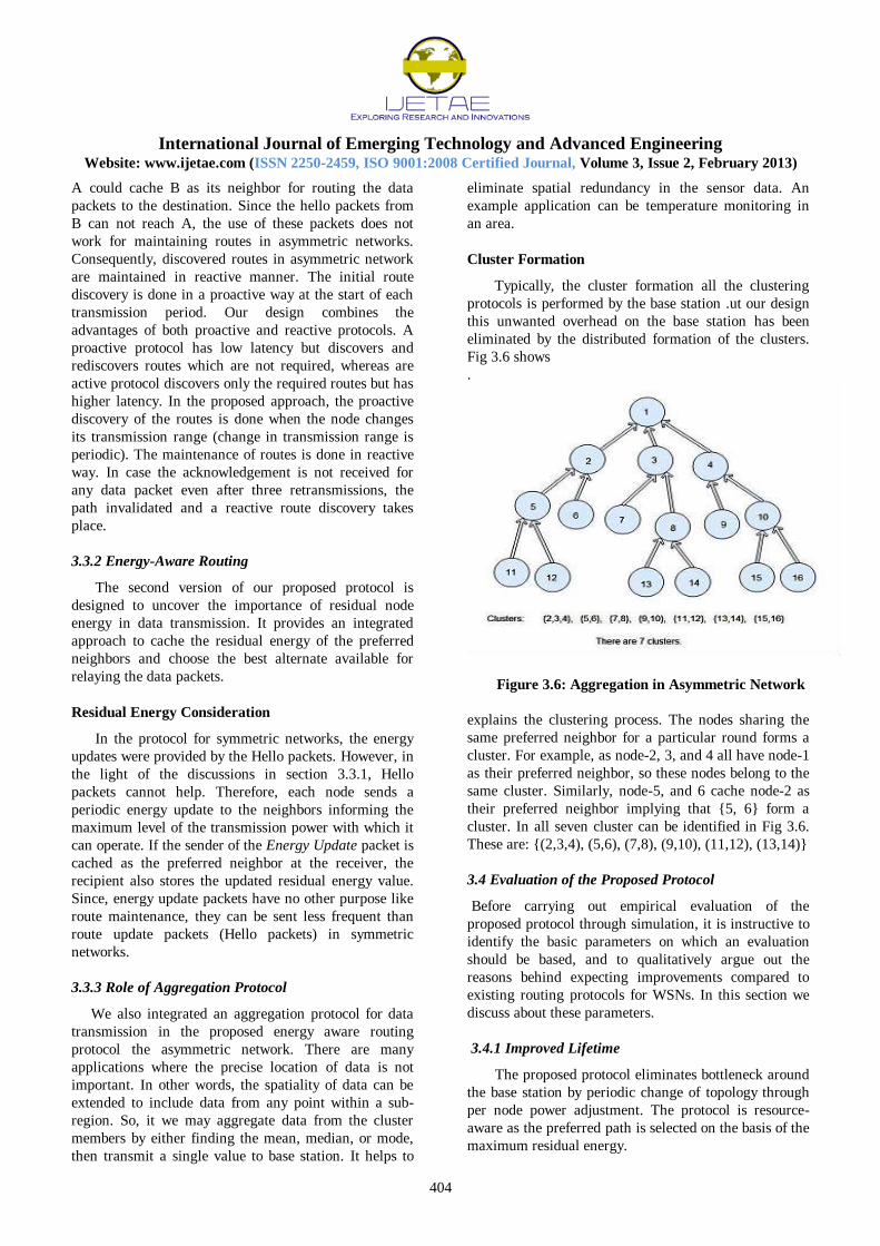
Fig 3.6 shows
.
Figure 3.6: Aggregation in Asymmetric Network
explains the clustering process. The nodes sharing the
same preferred neighbor for a particular round forms a
cluster. For example, as node-2, 3, and 4 all have node-1
as their preferred neighbor, so these nodes belong to the
same cluster. Similarly, node-5, and 6 cache node-2 as
their preferred neighbor implying that {5, 6} form a
cluster. In all seven cluster can be identified in Fig 3.6.
These are: {(2,3,4), (5,6), (7,8), (9,10), (11,12), (13,14)}
3.4 Evaluation of the Proposed Protocol
Before carrying out empirical evaluation of the
proposed protocol through simulation, it is instructive to
identify the basic parameters on which an evaluation
should be based, and to qualitatively argue out the
reasons behind expecting improvements compared to
existing routing protocols for WSNs. In this section we
discuss about these parameters.
3.4.1 Improved Lifetime
The proposed protocol eliminates bottleneck around
the base station by periodic change of topology through
per node power adjustment. The protocol is resource-
aware as the preferred path is selected on the basis of the
maximum residual energy.
International Journal of Emerging Technology and Advanced Engineering
Website: www.ijetae.com (ISSN 2250-2459, ISO 9001:2008 Certified Journal, Volume 3, Issue 2, February 2013)
405
Therefore, the proposed protocol when compared
with the existing protocols should results in better
network lifetime.
3.4.2 Resource-awareness
The design is resource-aware as is chooses the path
with maximum residual energy from among the existing
alternatives, for relaying the data packets to the base
station.
3.4.3 Reduced Message Complexity and Zero
Redundancy
There exists no redundancy in transmission of the
data packets. The redundancy in the route request
packets has been avoided by using the request ids in the
respective packets. Every node caches at most three
neighbors to be used as the preferred next hops for
relaying the data. Once three neighbors have been
discovered, further discovery is considered redundant.
The base station uses a REQ_CAN packet, which
contains the id of the requesting node and the sequence
number of the request. It is broadcast by the base station
once three neighbors for any node are discovered. Any
node on receiving this packet discards the route request
quoted by the REQ_CAN packet. Thus, this packet is
used as a death certificate for the route request packets
from a particular node and a specific sequence number.
3.4.4 Reliability
As the redundancy is reduced to the minimum level,
the overhead due to reliability is required to be
considered. There are acknowledgements for the data
packets. The protocol design supports at max three
retransmissions of a data packet. There is trade-off
concerning reliability versus redundancy. But reliability
in a way helps to eliminate requirement for redundancy.
3.4.5 Scalability
The protocol puts no constraint of the deployment
area. New nodes can be injected to the network. A new
node performs a reactive route discovery for a path to the
base station. It can be used as a forwarding node only
after the next proactive discovery takes place, or if there
is any reactive discovery before the next proactive
schedule.
3.4.6 Fault Tolerance
The protocol is dynamic enough to handle the node
failures. If a node fails, the packets relayed along that
path will result in no acknowledgements, so the paths
will be invalidated after three retransmissions.
If on invalidating the path, a node is left with no valid
path, it reactively starts
a new route discovery.
3.4.7 Load Balancing
Each node maintains three alternate preferred
neighbors to be used for relaying the data to the base
station. As the best is chosen based on the maximum
residual energy, the load is balanced among the three
neighbors.
3.4.8 Requirements for Specialized Support Parameters
Some routing protocols like LAR [15] or GAF [29]
make use of position vectors of the nodes to eliminate
flooding during route discovery. However, our proposed
protocol does not require any such additional support.
The protocol works independent of the location of the
individual nodes. Therefore, suited both for indoor and
outdoor networks. The routing algorithm is simple to
implement.
IV. SIMULATION RESULTS
In this chapter we present the results of
experiments carried out for evaluating the performance
of the proposed energy efficient routing protocol. For a
evaluation to be meaningful, the performance of the
proposed protocol should be compared with the
performances of certain well known existing energy
aware protocols. We base our evaluation primarily by
comparing with the performance of two other protocols,
namely, SPIN [11] and LEACH [12]. The choice of
these two protocols for performance comparison is
guided by two important reasons. SPIN’s approach is
based on eliminating data redundancies due to impolsion
and overlaps exhibited by plain flooding. On the other
hand, LEACH’s approach is to form random clusters in
each round so that the load of data transmission borne by
the cluster heads can be spread uniformly over all nodes.
So, LEACH cuts back overheads due communication by
localizing most of the communication through data
aggregation.
Since, the proposed protocol leverages cross layer
optimization for energy efficiency in WSN routing, it
should independently show performance enhancement
over symmetric routing protocols and over both SPIN
and LEACH even without data aggregation. The results
are discussed through plots accompanied by explanation
as needed.The simulation environment consists of 80
nodes uniformly randomly distributed over a space of of
(125X190)m2 Certain experiments have also been done
to see the effect of change in the network density over
the lifetime.

International Journal of Emerging Technology and Advanced Engineering
Website: www.ijetae.com (ISSN 2250-2459, ISO 9001:2008 Certified Journal, Volume 3, Issue 2, February 2013)
406
The node attributes chosen to strongly resemble
MICAz motes. A MICAz mote is a 2.4 GHz, IEEE
802.15.4 complaint chip. The mote module used for
enabling low power wireless interface. Since the indoor
range of for the sensor networks is 20m � 30m, the
transmission range variations are applied within this
range. As specified in the IEEE 802.15.4, we have used
the standard data packet size of 128b y tes. The
simulation assumes the base station to be fixed at the
origin and is a powerful node.
4.1 Node Placement
The plot in Fig. 4.1 shows the distribution of the
nodes. The base station or the control center is placed at
the origin, i.e., (0,0). The position of the other nodes are
randomly generated by the simulating software.
Fig- 4.1. Node Placement
The distribution followed is the random uniform
distribution. A black dot displays the position of a node,
the id of the node is written alongside the dot. The base
station id is 1, and the 80 sensor nodes are allocated ids
from 2 to 81.
4.2 Network Lifetime
As, already mentioned, one of the major objective of
this work has been to improve the lifetime of the sensor
networks. So we compare the lifetime in the proposed
methodology with the existing protocols. Typically, there
are three different measures for the lifetime of a WSN,
namely,
1. The time till the first node exhaust its energy,
2. The time till the last node exhaust its energy, and
3. The time till half the nodes in the network exhaust
their energy.
In this work, The first parameter has been used for the
purpose of comparison of different protocols.
Fig-4.2. Lifetime
The plot in Fig. 4.2 shows the improvement in the
lifetime obtained with the proposed methodology over
the existing symmetric protocol semantics. The five
protocols compared in this section are
SPIN: The transmission range of the nodes is
taken to be 29m, as this is the minimum range
when all nodes get at least one path to the base
station.
Symmetric Protocol: The transmission range used
is same as above.
Symmetric protocol with Residual Energy
Consideration: The transmission ranged used is
same as above.
Asymmetric Network: In this all nodes change their
transmission range between a fixed range in steps.
Parameter values:
1. Transmission Range: 20m�32m
2. Transmission Period: 12Nsec
3. Step Size: 3m
4.Asymmetric protocol with Residual Energy
Consideration: All the parameters are kept unchanged as
above. The Energy update packets are broadcast to the
neighbors every 5 secs.
4.3 Effect of Node Failure
The plots in this subsection are used to observe the
effect of node failure on the lifetime of the network when
the nodes near the base station fail.

International Journal of Emerging Technology and Advanced Engineering
Website: www.ijetae.com (ISSN 2250-2459, ISO 9001:2008 Certified Journal, Volume 3, Issue 2, February 2013)
407
The network configuration used for the purpose of
evaluation is as follows:
1. The period of the transmission range: 12Nsec.
2. The range between which transmission power is
varied: 20m to 32m.
3. The steps in which transmission range is varied:
6m.
4. The variation in percentage of node failures: 1%-
5%.
Fig-4.3. Effect of node failure on Lifetime
There is a trade-off between the following:
1. The total energy drained out of the network because of
the packets generated by centrally located nodes,
2. The total energy saved by the far-off nodes when they
use those centrally located for routing data packets.
The plot in Fig. 4.3 shows the effect on the lifetime of
the network when nodes far-off from the base station
fail. If the far-off nodes die then the lifetime shows an
improvement of about 7% with 5% nodes going dead. It
happens because the load due to the route discovery and
the data packet of the far-off nodes reduces. The nodes
near the base station are now less loaded and last longer.
4.4 Effect of Aggregation
The aggregation version of the proposed protocol has
been compared with the well known aggregation
protocol LEACH [12]. The lifetime obtained with
proposed approach was 150400sec which shows an
improvement of more than 400% is observed over
LEACH (27099sec). As already stated in chapter 2,
LEACH is not suited for such large area.
But still if we remove the constraint of the
transmission range and assume to use nodes with very
high transmission ranges, that is maximum of
approximately 250m, the proposed protocol outperforms
LEACH.
4.4.1 Clusters in LEACH
Although as mentioned in the chapter 2, LEACH can
work in this configuration with the assumption that the
nodes are able to increase their transmission range to
around 250m, the number of clusters to be formed are
taken to be 20% of the number of nodes. If the number is
higher then the performance goes down further. Since,
the total number of nodes is 80, the highest number of
clusters formed at any particular instant of the
simulation was 16. The total area covered by each
cluster is approximately 1500m2, which is large enough.
Fig-4.4. a) Clusters in LEACH
4.4.2 Effects of Aggregation in Proposed Protocol
The graph in Fig. 4.4. b) shows that by introducing
aggregation in the proposed asymmetric protocol,
around 40 clusters are formed at any particular instant of
the simulation. Therefore, the number of packets
delivered is much more than in the case LEACH as
depicted in Fig. 4.4. a). The total area covered by each
cluster in case of the asymmetric network is
approximately 600m2 which leads to better localization
of communication We addressed the following issues
through our experiments.

International Journal of Emerging Technology and Advanced Engineering
Website: www.ijetae.com (ISSN 2250-2459, ISO 9001:2008 Certified Journal, Volume 3, Issue 2, February 2013)
408
Energy efficiency: The lifetime of the network
increased by about 155% in comparison to the
symmetric network.
Scalability: The protocol is dynamic enough to handle
the failures and new insertions.
Low latency: As the protocol is a mixture of both
proactive and reactive protocols, the total delay factor is
3RT T + k, where k is a parameter introduced due to
congestion Reliability: It is an acknowledgment based
protocol. If acknowledgment is not received for a packet
till acknowledgment timeout, retransmissions take place.
Easy to implement: The implementation details
presented, clearly shows that the protocol is easy to
implement.
Fig-4.4.b) Clusters in Asymmetric Network with
Residual Energy Consideration
V. CONCLUSION
The work in this thesis is focused towards designing,
implementation and evaluation of energy efficient
routing protocols for wireless sensor networks. The
elimination of bottleneck around the base station is a
matter of major concern. The effort was directed towards
uniform distribution of data transmission and
dissemination load among the nodes across the network.
We realized that only way to achieve this is to develop a
methodology for distributed topology control. We
studied the specification of MICAz motes and came to
conclusion that by per-node transmission power
adjustment, it is possible to control topology and thus
eliminate the bottleneck around the base station.
It resulted in increase in the lifetime of the network.
Through a series of simulation experiments using
different network configurations, we observed that the
approach is justified and result in substantial
performance enhancements over existing energy aware
protocols. The proposed protocol when compared to the
symmetric multihop protocol was found to attain 155%
improvement in the lifetime. The aggregation version of
the proposed protocol showed an improvement of 400%
over the existing aggregation protocol LEACH.
REFERENCES
[1]. C. Schurgers and M. B. Srivastava, “Energy efficient
outing in wireless sensor networks,” in Proc. IEEE
Military Communications Conf. (MILCOM), 2001, pp.
357–361.
[2] D. Ganesan, R. Govindan, S. Shenker, and D. Estrin,
“Highly-resilient, energy-efficient multipath routing in
wireless sensor networks,” SIGMOBILE Mobile Comput.
Commun. Rev., vol. 5, no. 4, pp. 11–25, 2001.
[3] R. Shah and J. Rabaey, “Energy aware routing for low
energy ad hoc sensor networks,” in Proc. IEEE Wireless
Communications and Networking Conf. (WCNC), 2002,
pp. 350–355.
[4] J.-H. Chang and L. Tassiulas, “Maximum lifetime routing
in wireless sensor networks,” IEEE/ACMTrans. Netw., vol.
12, no. 4, pp. 609–619, Aug. 2004.
[5] G. Park, S. Yi, J. Heo, W. C. Choi, G. Jeon, Y. Cho, and C.
Shim, “Energy aware routing with dynamic probability
scaling,” in Lecture Notes in Computer Science. New
York: Springer, 2005, vol. 3642, pp. 662–670.
[6] C. Lu, B. Blum, T. Abdelzaher, J. Stankovic, and T. He,
“RAP: A real-time communication architecture for large-
scale wireless sensor networks,” in Proc. IEEE Real-Time
and Embedded Technology and Applications Symp.
(RTAS), 2002, pp. 55–66.
[7]. Wendi Heinzelman, Anantha Chandrakasan, and Hari
Balakrishnan. Energy-efficient communication protocols
for wireless microsensor networks. In Proceedings of the
33rd Annual Hawaii International Conference on System
Sciences, 2000, pages 10 pp. vol.2–, Jan 4-7, 2000.
[8] B. Hull, K. Jamieson, and H. Routing protocols overview
and design issues for selforganized networks. In
International Conference on Communication Technology
(WCCICCT), volume 2, pages 1298–1303, 2000.
[9] Chalermek Intanagonwiwat, Ramesh Govindan, and
Deborah Estrin. Directed diffusion: a scalable and robust
communication paradigm for sensor networks. In
MobiCom ’00: Proceedings of the 6th annual international
conference on Mobile computing and networking, pages
56–67, New York, NY, USA, 2000. ACM Press.
[10] Young-Bae Ko and Nitin H. Vaidya. Location-aided
routing (LAR) in mobile ad hoc networks. volume 6, pages
307–321, 2000.
[11] Philip Levis, Nelson Lee, Matt Welsh, and David Culler.
Tossim: accurate and scalable simulation of entire tinyos
applications. In SenSys ’03: Proceedings of the 1st
international conference on Embedded networked sensor
International Journal of Emerging Technology and Advanced Engineering
Website: www.ijetae.com (ISSN 2250-2459, ISO 9001:2008 Certified Journal, Volume 3, Issue 2, February 2013)
409
systems, pages 126–137, New York, NY, USA, 2003.
ACM.
[12] F. L. Lewis. Wireless sensor networks. In D. J. Cook and
S. K. Das, editors, Smart Environments: Technologies,
Protocols and Applications, pages 12–13. John Wiley,
New York, USA, 2004.
[13] X. Lin, N. B. Shroff, and R. Srikant. A tutorial on cross-
layer optimization in wireless networks. IEEE Journal
onSelected Areas in Communications, 24(8):1452–1463,
2006.
[14] Stephanie Lindsey and Cauligi S. Raghavendra. Pegasis:
Power-efficient gathering in sensor information systems,
2002.
[15] Arati Manjeshwar and Dharma P. Agrawal. Teen: A
routing protocol for enhanced efficiency in wireless sensor
networks. 15th International Parallel and Distributed
Processing Symposium (IPDPS’01), 03, 2001.
[16] Wendi Heinzelman, Anantha Chandrakasan, and Hari
Balakrishnan. Energy-efficient communication protocols
for wireless microsensor networks. In Proceedings of the
33rd Annual Hawaii International Conference on System
Sciences, 2000, pages 10 pp. vol.2–, Jan 4-7, 2000.
[17] Arati Manjeshwar and Dharma P. Agrawal. Apteen: A
hybrid protocol for efficient routing and comprehensive
information retrieval in wireless sensor networks. In
IPDPS ’02: Proceedings of the 16th International Parallel
and Distributed Processing Symposium, page 48, 2002.
[18] J. Neander, E. Hansen, M. Nolin, and M. Björkman.
Asymmetric multihop communication in large sensor
networks. In Wireless Pervasive Computing, 2006 1st
International Symposium on, pages 7 pp.–, 16-18 Jan.
2006.
[19] J. Neha, D. K. Madathil, and D. P. Agrawal. Exploiting
multi-path routing to achieve service differentiation in
sensor networks. In 11th IEEE International Conference
on Networks (ICON), pages 681–686, October, 2003.
[20] Kumar Padmanabh and Rajarshi Roy. Bottleneck around
base station in wireless sensor network and its solution. In
Mobile and Ubiquitous Systems - Workshops, 2006. 3rd
Annual International Conference on, pages 1–5, 17-21
July 2006.
[21] Charles Perkins and Pravin Bhagwat. Highly dynamic
destination-sequenced distancevector routing (DSDV) for
mobile computers. In ACM SIGCOMM’94 Conference on
Communications Architectures, Protocols and
Applications, pages 234–244, 1994.
[22] Sharmila Ravula, Ji Eun Kim, Brad Petrus, and Christoph
Stoermer. Quality attributes in wireless sensor networks.
Third IEEE Workshop on Software Technologies for
Future Embedded and Ubiquitous Systems (SEUS’05),
00:30–32, 2005.
[23] Rahul C. Shah and Jan Rabaey. Energy aware routing for
low energy ad hoc sensor networks. In Wireless
Communications and Networking Conference, 2002.
WCNC2002. 2002 IEEE, volume 1, pages 350–355, 17-21
Mar 2002.
[25] Ya Xu, John Heidemann, and Deborah Estrin. Geography-
informed energy conservation for ad hoc routing. In
MobiCom ’01: Proceedings of the 7th annual international
conference on Mobile computing and networking, pages
70–84, New York, NY, USA, 2001.
[26]. ACM. Documentation and tutorials for omnet++.
http://www.omnetpp.org/.
[27]Micaz 2.4 ghz data sheet.
http://www.davidson.com.au/products/wireless/
crossbow/mica-2-4.asp. [26]The network simulator ns-2.
http://www.isi.edu/nsnam/ns.
AUTHORS PROFILE
K.Vinoth Kumar received the B.E. degree in electronics and communication engineering from the Kurinji College of engineering and technology, Manapparai, Anna University, Chennai, India, in 2009. He received the M.E. degree in Applied electronics from the J.J College of engineering and technology, Trichirappalli, India, in
2011. Currently doing Ph.D. in communication and Networking in Karpagam University Coimbatore. His research interest includes wireless communication, Mobile Ad hoc networks, Sensor Networks, Communication networks.
S.Karthikeyan received the M.Sc
degree in Industrial electronics from
the M.I.E.T, college of arts and
science, trichirappalli India, in
2011.Currently doing M.E. in VLSI
design in Karpagam University
Coimbatore, India. His research
interest includes wireless
communication (WiFi,WiMax),
Mobile Ad hoc networks and low power VLSI
Paste
Photo
here