multilateral installation
TRANSCRIPT

Vermilion Oil & Gas Australia
2010 Wandoo Drilling Project OverviewMarch, 2011
Rod Gibbons, Vermilion Senior Production Engineer
Mike Zimmerman, Halliburton Sperry Operations Manager

Surface Facilities
Wandoo A
Wandoo B
CALM Buoy
• 18 wells on production (gas lift)
• 1 gas injection well
• Produced water limit 24,600m3/day
• Gas compression 890e3m3/day
• Processing on Wandoo B with flowlines between A and B;
• 8” Production Line
• 3” Gas Lift Line
– Export Line to CALM Buoy

Reservoir Parameters
Shallow, unconsolidated reservoir at ~600m
TVDss (AHD)
Thin oil column (22m) with overlying gas cap
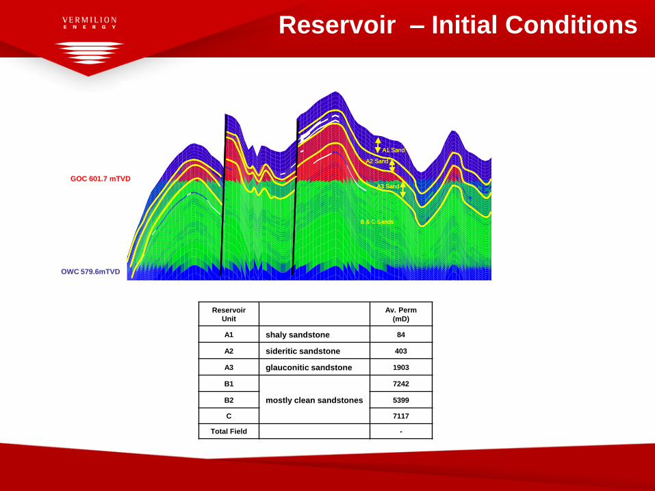
Original FWL 601.7 m TVDss (AHD)
Original GOC 579.6 m TVDss (AHD)
Oil Properties
19o API, in-situ viscosity 14cp, low GOR 17m3/m3
STOIIP ~200 mmbbl
Gas Cap ~9 Bcf
Associated Gas ~18 Bcf
Current production is ~9,000bbls/day
Initial reservoir pressure 898 psi (6194 kPa)
Current reservoir pressure 783 psi (5400 kPa)
A Platform
B Platform

Production History
Wandoo Production History
0
5,000
10,000
15,000
20,000
25,000
30,000
35,000
40,000
45,000
50,000
1997 1998 1999 2000 2001 2002 2003 2004 2005 2006 2007 2008 2009 2010
Oil
Ra
te (
bb
ls/d
ay
) 1997 Gravity Based Structure
Installed
Vermilion
gets
operatorship
2006 –
2007
Facility
Debottle-
necking
2008
Drilling
Campaign
Reservoir
Unit
Av. Perm
(mD)
A1 shaly sandstone 84
A2 sideritic sandstone 403
A3 glauconitic sandstone 1903
B1 7242
B2 mostly clean sandstones 5399
C 7117
Total Field -
Reservoir – Initial Conditions
7,772,000 7,773,000 7,774,000 7,775,000
7,772,000 7,773,000 7,774,000 7,775,000
550
560
570
580
590
600
610
540
550
560
570
580
590
600
610 0.00 0.25 0.50 0.75 1.00 mile
0.00 0.25 0.50 0.75 1.00 km
File: Pred_2010_Base_NFA.irf
User: rjefferies
Date: 20/05/2010
Scale: 1:26939
Z/Y: 50.00:1
Axis Units: m
1.00
Sw
1.00
So
Sg
1.00
Min Values:
Sw = 0.000
So = 0.000
Sg = 0.000
Base_NFA 2010
Ternary 1993-09-30 I layer: 3
A1 Sand
A2 Sand
A3 Sand
B & C Sands
7,772,000 7,773,000 7,774,000 7,775,000
7,772,000 7,773,000 7,774,000 7,775,000
550
560
570
580
590
600
610
540
550
560
570
580
590
600
610 0.00 0.25 0.50 0.75 1.00 mile
0.00 0.25 0.50 0.75 1.00 km
File: Pred_2010_Base_NFA.irf
User: rjefferies
Date: 20/05/2010
Scale: 1:26939
Z/Y: 50.00:1
Axis Units: m
1.00
Sw
1.00
So
Sg
1.00
Min Values:
Sw = 0.000
So = 0.000
Sg = 0.000
Base_NFA 2010
Ternary 1993-09-30 I layer: 3
A1 Sand
A2 Sand
A3 Sand
B & C Sands
A1 Sand
A2 Sand
A3 Sand
B & C Sands
GOC 601.7 mTVD
OWC 579.6mTVD
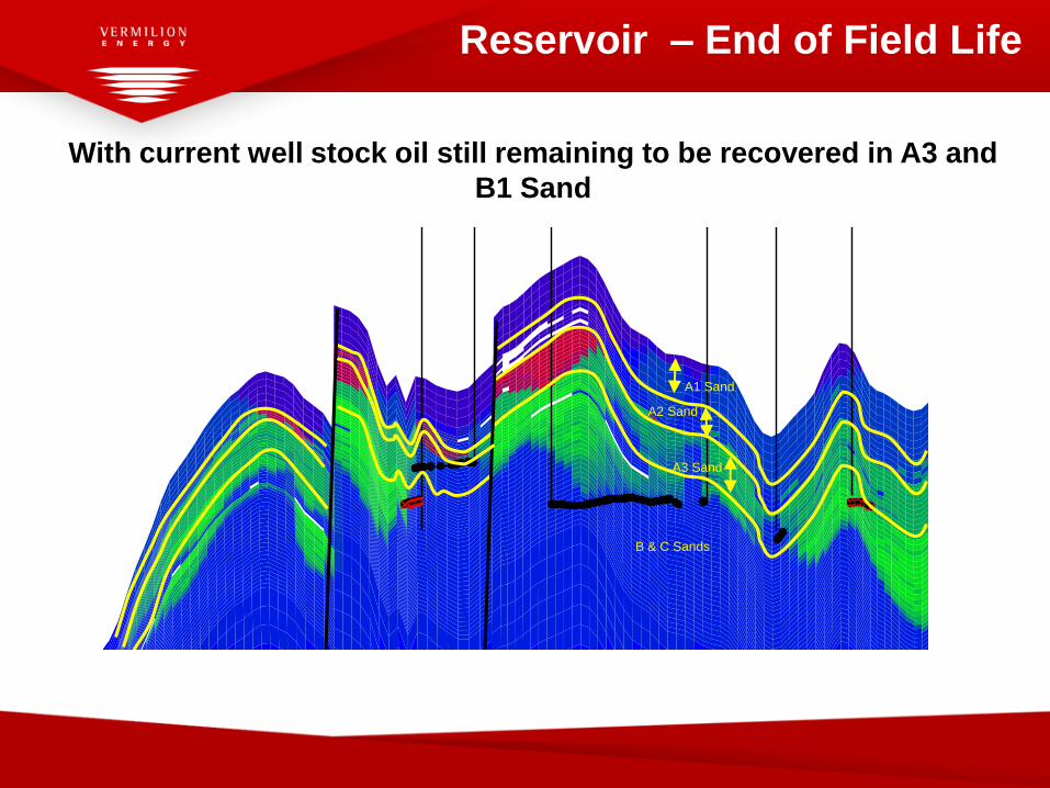
Reservoir – End of Field Life
WA5 WB12ST2WB13H WB1AWB5 WB6
7,772,000 7,773,000 7,774,000 7,775,000
7,772,000 7,773,000 7,774,000 7,775,000
550
560
570
580
590
600
610
540
550
560
570
580
590
600
610 0.00 0.25 0.50 0.75 1.00 mile
0.00 0.25 0.50 0.75 1.00 km
File: Pred_2010_Base_NFA.irf
User: rjefferies
Date: 20/05/2010
Scale: 1:26939
Z/Y: 50.00:1
Axis Units: m
1.00
Sw
1.00
So
Sg
1.00
Min Values:
Sw = 0.000
So = 0.000
Sg = 0.000
Base_NFA 2010
Ternary 2029-12-31 I layer: 3
A1 Sand
A2 Sand
A3 Sand
B & C Sands
With current well stock oil still remaining to be recovered in A3 and
B1 Sand

2008 Well Campaign
A Deck Extension on Wandoo
B was constructed to
accommodate additional wells
in the Wandoo Field

Impact of 2010 Drilling Campaign
Remaining Oil at 2029 Comparison
WA1
WA2
WA3
WA4
WA5
WA6
WA6H1
WA7WA8ST1
WA9
WB10ig
WB11
WB12ST2
WB13H
WB14H
WB14Pilot
WB1A
WB2A
WB3
WB4A WB5
WB6
WB7
WB8A
WB9
438,000 439,000 440,000 441,000 442,000 443,000
438,000 439,000 440,000 441,000 442,000 443,000
7,7
72
,00
07
,77
3,0
00
7,7
74
,00
07
,77
5,0
00
7,7
72
,00
07
,77
3,0
00
7,7
74
,00
07
,77
5,0
00
0.00 0.25 0.50 0.75 1.00 km
File: Pred_2010_Base_NFA.irf
User: rjefferies
Date: 14/05/2010
Scale: 1:29738
Y/X: 1.00:1
Axis Units: m
0.0
0.7
1.3
2.0
2.7
3.4
4.0
4.7
5.4
6.0
6.7
Base_NFA 2010Oil Per Unit Area - Total (m) 2028-12-31 K layer: 46
WA1
WA2
WA3
WA4
WA5
WA6
WA6H1
WA7WA8ST1
WA9
WB10ig
WB11
WB12ST2
WB13H
WB14H
WB14Pilot
WB1A
WB2A
WB3
WB4A WB5
WB6
WB7
WB8A
WB9
439,000 440,000 441,000 442,000 443,000
439,000 440,000 441,000 442,000 443,000
7,7
72
,00
07
,77
3,0
00
7,7
74
,00
07
,77
5,0
00
7,7
72
,00
07
,77
3,0
00
7,7
74
,00
07
,77
5,0
00
0.00 0.25 0.50 0.75 1.00 km
File: Pred_A6B8B12Combined.irf
User: rjefferies
Date: 14/05/2010
Scale: 1:29870
Y/X: 1.00:1
Axis Units: m
0.0
0.7
1.3
2.0
2.7
3.4
4.0
4.7
5.4
6.0
6.7
A6B8B12Oil Per Unit Area - Total (m) 2029-12-31 K layer: 46
Base Case 2010 Flank Upside WellsB12
Lateral
A6
Lateral
B8
Lateral

Multi-Lateral Junctions
• Alternative methods of accessing reserves were
evaluated in 2009, including;
– Conventional horizontals from new conductors in a deck
extension,
– Abandoning wells and recovering well slots,
– Multilaterals,
– Through tubing drilling,
– Drilling iron - Jack-up, Platform based rig, Hydraulic
workover unit, coiled tubing drilling.
• The optimum balance of innovation and proven
technology was to use a conventional Jack-up drilling rig
and use multilateral technology.

Development Alternatives 2010 – Coiled Tubing
on Platform
• Removing the Mechanical Plug from well B12 with a coiled tubing unit removed this task off the drilling program critical path and allowed production testing before the well was sidetracked.
WA1
WA2
WA3
WA4
WA5
WA6
WA6H1
WA7WA8ST1
WA9
WB10ig
WB11
WB12ST2
WB13H
WB14H
WB14Pilot
WB1A
WB2A
WB3
WB4A WB5
WB6
WB7
WB8A
WB9
438,000 439,000 440,000 441,000 442,000 443,000
438,000 439,000 440,000 441,000 442,000 443,000
7,7
72
,00
07
,77
3,0
00
7,7
74
,00
07
,77
5,0
00
7,7
72
,00
07
,77
3,0
00
7,7
74
,00
07
,77
5,0
00
0.00 0.25 0.50 0.75 1.00 km
File: Pred_2010_Base_NFA.irf
User: rjefferies
Date: 14/05/2010
Scale: 1:29738
Y/X: 1.00:1
Axis Units: m
0.0
0.7
1.3
2.0
2.7
3.4
4.0
4.7
5.4
6.0
6.7
Base_NFA 2010Oil Per Unit Area - Total (m) 2028-12-31 K layer: 46

Development Alternatives 2010
Adding laterals onto existing
wellbores eliminated the need
for additional well slots and
space on the surface facilities
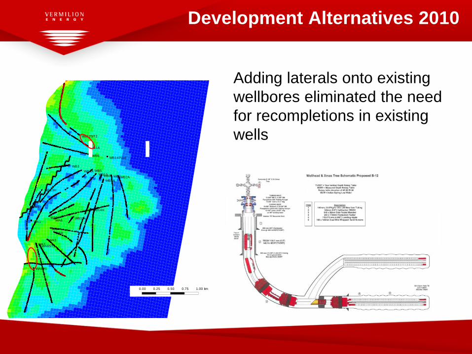
Development Alternatives 2010
Adding laterals onto existing
wellbores eliminated the need
for recompletions in existing
wells
WA1
WA2
WA3
WA4
WA5
WA6
WA6H1
WA7WA8ST1
WA9
WB10ig
WB11
WB12ST2
WB13H
WB14H
WB14Pilot
WB1A
WB2A
WB3
WB4A WB5
WB6
WB7
WB8A
WB9
438,000 439,000 440,000 441,000 442,000 443,000
438,000 439,000 440,000 441,000 442,000 443,000
7,7
72
,00
07
,77
3,0
00
7,7
74
,00
07
,77
5,0
00
7,7
72
,00
07
,77
3,0
00
7,7
74
,00
07
,77
5,0
00
0.00 0.25 0.50 0.75 1.00 km
File: Pred_2010_Base_NFA.irf
User: rjefferies
Date: 14/05/2010
Scale: 1:29738
Y/X: 1.00:1
Axis Units: m
0.0
0.7
1.3
2.0
2.7
3.4
4.0
4.7
5.4
6.0
6.7
Base_NFA 2010Oil Per Unit Area - Total (m) 2028-12-31 K layer: 46
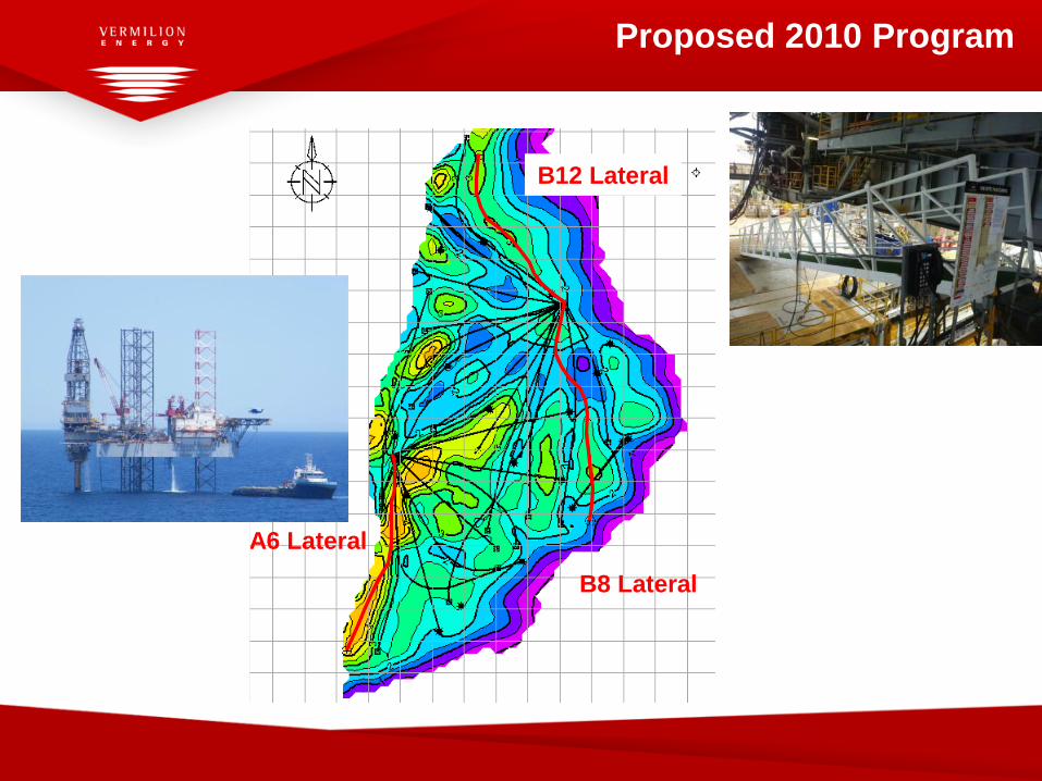
Proposed 2010 Program
A3/B Sand Oil Thickness End 2009
A6 Lateral
B8 Lateral
B12 Lateral
A3/B Sand Oil Thickness End 2009
A6 Lateral
B8 Lateral
B12 Lateral

Drilling & Completion Installation

ERD Well Designs
Wandoo Sidetracks
Conventional
Extended Reach ( >2 : 1 stepout down to 2000-2500m TVD)
Extended Reach = very ER (>3 : 1 stepout)
Extended Reach = extreme ER

16 16161616
Drag Risk - Sandscreens
A6 with 5.5” & 6.875” Screens 9” OH
from 960mContingency w/400m CH Rollers on top
5.5” Screens
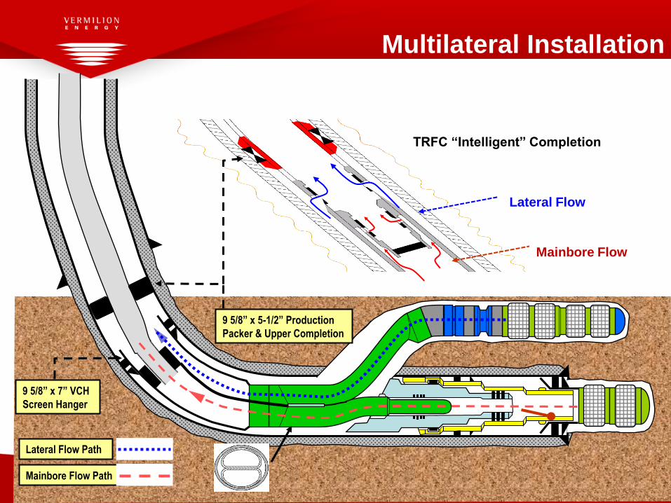
9 5/8” x 7” VCH
Screen Hanger
Lateral Flow Path
Mainbore Flow Path
9 5/8” x 5-1/2” Production
Packer & Upper Completion
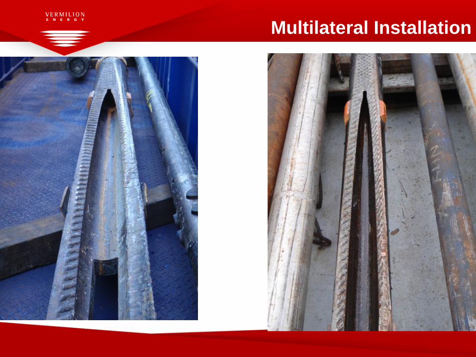
Multilateral Installation
Lateral Flow
Mainbore Flow
TRFC “Intelligent” Completion
Multilateral “Evolution”
ReFlexRite Generation 3 - Halliburton ReFlexRite components are from existing ML designs.
1. FlexRite for junction
Subsea TAML level 5: Quick Installation, Reliable, Simple Operations
Used extensively – over 120 installed and 9 junctions installed prior to Wandoo.
2. MillRite for milling window
Milling machine cuts straight window, whipstock installed to open window and allow drilling assemblies to exit and re-enter.
Versatile – Can create level 2 through level 5 junctions.
Used extensively – over 60 installations – including 1 in Australia – to date.
3. Packers from existing product lines
4500 system - Large Bore Anchor packer is for re-entering existing wells,anchor point for whipstock and completion.
Proven ratch-latch design for anchor mechanism on all subsequent tool runs.
Redesigned running tool, enables orientation via MWD.
Multilateral Type
ReFlexRite Generation 3 – Halliburton
Level 5 Junction
• Non cemented, mechanical sealed junction – 1,200psi
Sealing Mechanism
Completion Deflector
• Completion Defector stinger seals into Anchor Packer tail pipe PBR
FlexRite Junction
• Junction stinger OD seals into the inside of Completion Deflector which has a stack of
several concentric polymer “T-seals” on the ID
• “T-seals” are protected when running the Completion Deflector by the HMRT (running tool)
Minimal Steps for Installation
• Mechanical seal - non cemented
• No open hole sting-in
• Two trip window opening system
• One trip milling casing – precision milling machine
• One trip window opening with whipstock milling assembly
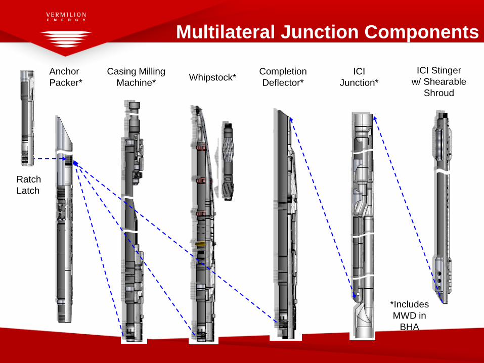
Multilateral Junction Components
Anchor
Packer*
Ratch
Latch
Casing Milling
Machine*Whipstock*
Completion
Deflector*
ICI
Junction*
ICI Stinger
w/ Shearable
Shroud
*Includes
MWD in
BHA

Lower Screen
Mainbore Completion
9 5/8” Shoe
13 3/8”
Shoe
Production packer milled and Upper completion retrieved.
2 runs on B-12, 1 run on B-8 and A-6
Well is clean and drifted.
Casing evaluation tool runs have been performed in the 9 5/8”casing,
preferably to the expected junction location area.
Casing tallies were all accurate.
Suitable packer setting area has been identified.
Suitable casing exit joint has been identified, to enable drilling of lateral
branch.
Well Prep for Casing Exit Option - Above 9 5/8” Shoe
Multilateral Installation
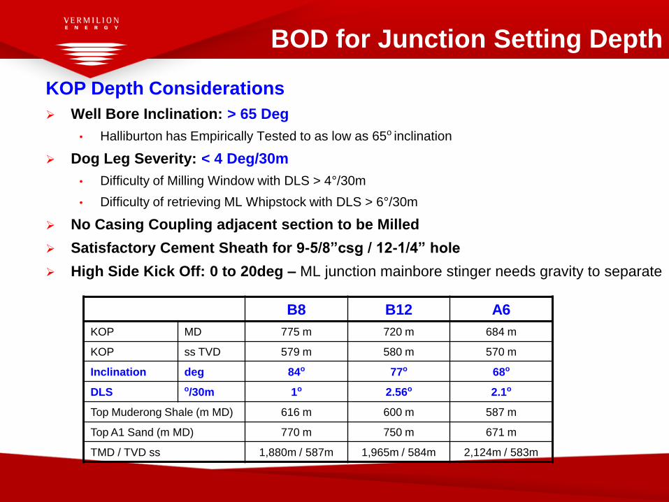
KOP Depth Considerations
Well Bore Inclination: > 65 Deg
• Halliburton has Empirically Tested to as low as 65o inclination
Dog Leg Severity: < 4 Deg/30m
• Difficulty of Milling Window with DLS > 4°/30m
• Difficulty of retrieving ML Whipstock with DLS > 6°/30m
No Casing Coupling adjacent section to be Milled
Satisfactory Cement Sheath for 9-5/8”csg / 12-1/4” hole
High Side Kick Off: 0 to 20deg – ML junction mainbore stinger needs gravity to separate
BOD for Junction Setting Depth
B8 B12 A6
KOP MD 775 m 720 m 684 m
KOP ss TVD 579 m 580 m 570 m
Inclination deg 84o 77o 68o
DLS o/30m 1o 2.56o 2.1o
Top Muderong Shale (m MD) 616 m 600 m 587 m
Top A1 Sand (m MD) 770 m 750 m 671 m
TMD / TVD ss 1,880m / 587m 1,965m / 584m 2,124m / 583m
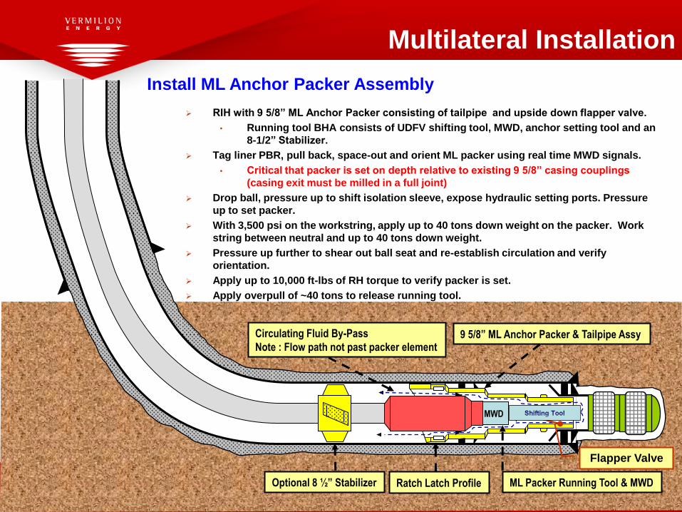
23Optional 8 ½” Stabilizer
9 5/8” ML Anchor Packer & Tailpipe Assy
Ratch Latch Profile ML Packer Running Tool & MWD
Install ML Anchor Packer Assembly
RIH with 9 5/8” ML Anchor Packer consisting of tailpipe and upside down flapper valve.
• Running tool BHA consists of UDFV shifting tool, MWD, anchor setting tool and an
8-1/2” Stabilizer.
Tag liner PBR, pull back, space-out and orient ML packer using real time MWD signals.
• Critical that packer is set on depth relative to existing 9 5/8” casing couplings
(casing exit must be milled in a full joint)
Drop ball, pressure up to shift isolation sleeve, expose hydraulic setting ports. Pressure
up to set packer.
With 3,500 psi on the workstring, apply up to 40 tons down weight on the packer. Work
string between neutral and up to 40 tons down weight.
Pressure up further to shear out ball seat and re-establish circulation and verify
orientation.
Apply up to 10,000 ft-lbs of RH torque to verify packer is set.
Apply overpull of ~40 tons to release running tool.
Circulating Fluid By-Pass
Note : Flow path not past packer element
MWD
Flapper Valve
Multilateral Installation
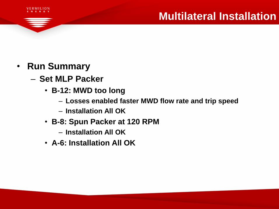
• Run Summary
– Set MLP Packer
• B-12: MWD too long
– Losses enabled faster MWD flow rate and trip speed
– Installation All OK
• B-8: Spun Packer at 120 RPM
– Installation All OK
• A-6: Installation All OK
Multilateral Installation

Install 9 5/8” Milling Machine
M/U milling machine and BHA.
RIH with ReFlexRite milling machine and land in Ratch Latch profile in MLP anchor
packer.
Confirm orientation using MWD signals, perform overpull test.
Circulate to release Hydraulic Locking Tool (HLT).
Mill 1st pass window.
• Cuttings captured in integral junk basket
• Optional magnet sub can be run below assembly for additional steel capture
Pull back and lock HLT into MillRite throat.
Release MillRite by straight overpull. POOH.
Note: Effective debris management to ensure removal of steel debris generated during milled
operations is of paramount importance to ensure junction construction is successful in ML
installations.
Mill Ramp Ratch Latch & Integral Junk Basket
Mill
(end position)
MillRite Guide & Throat
Multilateral Installation
Flapper
Valve
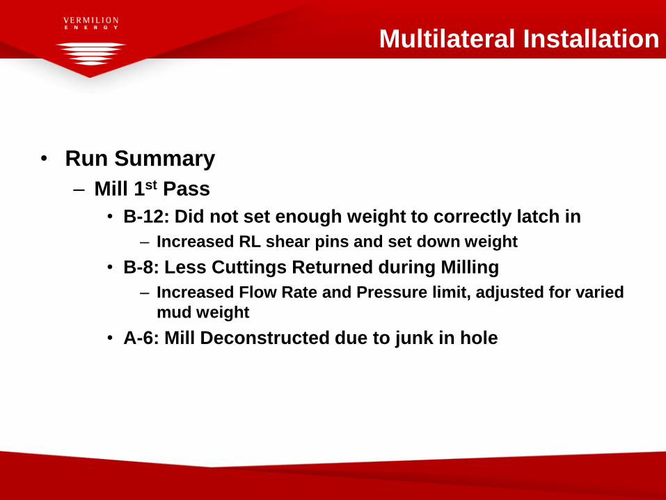
• Run Summary
– Mill 1st Pass
• B-12: Did not set enough weight to correctly latch in
– Increased RL shear pins and set down weight
• B-8: Less Cuttings Returned during Milling
– Increased Flow Rate and Pressure limit, adjusted for varied
mud weight
• A-6: Mill Deconstructed due to junk in hole
Multilateral Installation


Contingent: Perform Clean Up Run
Perform clean up run with magnets, brush and junk baskets.
Brush inside packer head to remove milling debris from latch
Dependent on cuttings recovery with Milling Machine.
Not Conducted on B-12 – Sufficient cuttings return
Brush
1st pass milled window
Multilateral Installation

Install ReFlexRite Drilling Whipstock
Ratch Latch
ReFlexRite Drilling Whipstock
8 ½” Lead & Watermelon Milling Assembly
M/up whipstock BHA
• Include magnet assembly
M/up whipstock assembly to lead mill with shear bolt, RIH.
• Whipstock can also be installed on a Hydraulic Running Tool.
Orient whipstock packer muleshoe and engage ratch latch.
Perform overpull test to verify whipstock is latched.
Confirm whipstock orientation using MWD signals.
Record circulating pressure at known flow rate.
Prepare to shear milling assembly free.
Magnet
Filter
Multilateral Installation

Ratch Latch
Open Up First Pass Milled Window To Full Gauge
Apply torque and set down weight to shear running bolt.
• 20 ton shear bolt
Pull mill free from window.
Open up 1st pass window to 8 1/2” full gauge, for lateral drilling
operations.
Mill 5.5-7m from first observation of milling torque (=1.5-3m formation).
Ream & drift window with mills.
Circulate clean and POOH.
MWD
ReFlexRite Drilling Whipstock
Filter
Magnet
Multilateral Installation

• Run Summary – Second Pass
– B-12: Run #1
• Whipstock set as planned
• Shear bolt sheared as planned
• Milled window, 1.5 m centered on taper face, 3.5 m on RHS
– B-12: Run #2
• Stiffer Milling BHA
• Bolt sheared premature
• Opened window *slightly* to the left
Multilateral Installation
Multilateral Installation

• Run Summary – Second Pass
– B-8:
• Whipstock set as planned
• Bolt sheared as planned
• Milled window, dressed window repeatedly, good returns (14.2
kg)
– A-6:
• Set whipstock as planned
• Bolt sheared as planned
• Run Stiff Milling BHA
Multilateral Installation

Drill the Lateral Branch To TD
2 Stage Drillout:
• Drill with PDM to ensure high build and correct landing
depths
• Aiming for 10-12°/30m for 1st section.
• i.e. “follow” whipstock angle of 2.9°/3m
• Drill with 8 ½” bit , 9” Underreamer and RSS assembly.
Displace or condition mud prior to coming out of hole.
POOH with drilling BHA.
Ratch LatchReFlexRite Drilling Whipstock Magnet
Multilateral Installation

Drilling Assembly Run #1
8.5”
PDM
Drilling
BHA
8.500
8.5in Motor BHA
Description Vendor Serial # OD/ID Max OD
Connection
(Bottom/Top)
Gender
(Bot/Top)
(in) (in) (in)
5.750 0
2.250 4 1/2 REG Pin
7.000 4 1/2 REG Box
5.500 4 1/2 REG Box
6.750 4 1/2 REG Pin
2.810 5 1/2 FH Box
6.750 5 1/2 FH Pin
5.109 4 1/2 NC50 (4 1/2 IF) Box
6.750 4 1/2 NC50 (4 1/2 IF) Pin
2.813 4 1/2 NC50 (4 1/2 IF) Box
5.000 4 1/2 NC50 (4 1/2 IF) Pin
3.000 4 1/2 NC50 (4 1/2 IF) Box
6.500 4 1/2 NC50 (4 1/2 IF) Pin
2.750 4 1/2 NC50 (4 1/2 IF) Box
5.000 4 1/2 NC50 (4 1/2 IF) Pin
3.000 4 1/2 NC50 (4 1/2 IF) Box
4.855 4 1/2 NC50 (4 1/2 IF) Pin
4.276 4 1/2 NC50 (4 1/2 IF) Box
BHA Comments
Blade Length (m) Blade Mid-Pt to Bit (m)
0.357 0.838
Gamma Ray
Resistivity
Gamma Ray
D+I
Bend Angle (deg) Bend to Bit (m)
1.500 2.143
Mud Weight (g/cm3) 1.58Funnel Viscosity (s)
18.861
Mud Properties
B12*
PV (cP)
Type
YP (lbf/100ft2)
Distance to Bit (m)
Rig5" 19.50 DPS, Premium
Vermillion/14-L/Wandoo Hole Size (in)
3
4
12.402
Sensor
2
18.215
BHA Name
Stabilizer Summary
Bend Summary
6.500Hydra-Jar
6.625
Heavy Weight Drill Pipe
8 1/2 " Bit
10.677
Generic
Field Name
Well Name
1
6.500
5
6
7
8
6.750
HE
Rig
6.890
Schlumberger
6.500
9
8.375
Schlumberger
Rig
7.500
A700M7866GT (1.5 deg Bend) Schlumberger
SchlumbergerPeriscope 675
Telescope 675 NF
NMDC
Heavy Weight Drill Pipe
8.500

8.5” x 9”
RSS
Drilling
BHA
9.000
Description Vendor Serial # OD/ID Max OD
Connection
(Bottom/Top)
Gender
(Bot/Top)
(in) (in) (in)
5.750 0
2.250 4 1/2 REG Pin
6.750 4 1/2 REG Box
5.160 5 1/2 FH Box
6.750 5 1/2 FH Pin
2.810 5 1/2 FH Box
6.750 5 1/2 FH Pin
5.109 5 1/2 FH Box
6.750 5 1/2 FH Pin
2.250 4 1/2 NC50 (4 1/2 IF) Box
6.750 4 1/2 NC50 (4 1/2 IF) Pin
3.000 4 1/2 NC50 (4 1/2 IF) Box
6.750 4 1/2 NC50 (4 1/2 IF) Pin
2.875 4 1/2 NC50 (4 1/2 IF) Box
6.750 4 1/2 NC50 (4 1/2 IF) Pin
1.500 4 1/2 NC50 (4 1/2 IF) Box
5.000 4 1/2 NC50 (4 1/2 IF) Pin
3.000 4 1/2 NC50 (4 1/2 IF) Box
6.500 4 1/2 NC50 (4 1/2 IF) Pin
2.750 4 1/2 NC50 (4 1/2 IF) Box
5.000 4 1/2 NC50 (4 1/2 IF) Pin
3.000 4 1/2 NC50 (4 1/2 IF) Box
4.855 4 1/2 NC50 (4 1/2 IF) Pin
4.276 4 1/2 NC50 (4 1/2 IF) Box
BHA Comments
Blade Length (m) Blade Mid-Pt to Bit (m)
0.506 0.64
0.506 3.688 D+I
0.762 23.131 Gamma Ray
0.610 30.185 Resistivity
1.280 32.852 Gamma Ray
D+I
Density
Bend Angle (deg) Bend to Bit (m) Neutron
0.600 0.71
Mud Weight (g/cm3) 1.58Funnel Viscosity (s)
Mud Properties
PV (cP)
Type
YP (lbf/100ft2)
Distance to Bit (m)
A06, B12, B28.5in Xceed +
Anderreamer BHABHA Name
24.296
Hole Size (in)
17.166
8.250
6.500
16.520
2
10.708
Bend Summary
25.274
8.5 x 9 Anderreamer
8-1/2 x 9" Xceed BHA
1.097
8.982
SensorStabilizer Summary
3
4
Rig
Rig
8.250
5" 19.50 DPS, Premium
8-1/4" Stab
8
9
10
11
5
6
7
Generic
Field Name
Well Name
1
Vermillion/14-L/Wandoo
9.000
Heavy Weight Drill Pipe 6.500
HE
Schlumberger
Andergauge
6.500RigHeavy Weight Drill Pipe
Schlumberger
Schlumberger
Schlumberger
6.890
Schlumberger
6.750
12
8.375
6.625
Periscope 675
Telescope 675 NF
ADN-6 w/ 8 1/4" Stabilizer
Pony NMDC
7.500
Hydra-Jar
Schlumberger
8 1/2 " Bit 8.500
Xceed 675 8 3/8" Stabilizers
Drilling Assembly Run #2

Directional Drilling Assemblies
Kick Off Drilling Assembly
DLS: 6° - 7° /30m in the hole section from KOP to End of Build (EOB) (target depth)
Near upper range of the Rotary Steerable System (8° /30m), PDM used to drill the initial
section of lateral.
Review of Wandoo drilling history could not confirm RSS performance where DLS’s were
> 4° /30m
Measurement / Logging While Drilling
The initial hole section from KO to EOC drilled with PDM assembly including MWD/GR
and PWD
From EOC to TD a RSS assembly with MWD/GR, Resistivity, Neutron Density, PWD and
Caliper.
This hole section also included an under reamer to open hole to 9” OD in the Production
Interval
Geo-steered at ~0.5m below the A3 sand utilising the LWD readings

Retrieve ReFlexRite Drilling Whipstock
RIH with Whipstock Hydraulic Retrieval Tool (HRT)
• ID Contingency retrieval method: spear assembly
• OD Contingency retrieval method: washover assy & die collar
Wash down with HRT into whipstock bore, tag stop ring and
engage whipstock ID retrieval profile.
Pull whipstock free with ~18 – 30 tons, POOH.
Whipstock HRT BHA
Ratch LatchReFlexRite Drilling Whipstock Magnet
Filter
Multilateral Installation

• Run Summary – Whipstock Recovery - HRT
– B-12 #1
• HRT worked as planned
• Ran with Jars and Bumper Sub
– B-12 #2
• HRT worked as planned
• Stabbed Whipstock back into MLP, damaged Whipstock
– B-8:
• HRT worked as planned
• Ran with Jars and Intensifier
– A-6:
• HRT worked as planned
• Ran with Jars
Multilateral Installation

Multilateral Installation

Install Completion Deflector & Tailpipe Assy
Assembly includes 6” seal unit with required spaceout tubing for landing
in MLP Anchor Packer intermediate completion assembly.
RIH, and enter ML anchor packer bore.
Orient and land completion deflector in Ratch Latch profile in MLP
anchor packer.
Set down weight to confirm landed, and circulate through MWD to
confirm correct orientation with weight set down on deflector.
Perform overpull test.
Release deflector running tool with flow rate (ΔP over nozzle). POOH.
MWD
Deflector Running Tool
ReFlexRite Completion Deflector
Deflector Seal Stack
Circulating Fluid By-Pass
Multilateral Installation

• Run Summary – Completion Deflector
– B-12 Run #1:
• HMRT performed as planned
• HMRT release flow rate: 580 GPM/2330 PSI
• Likely Sheared USDFV
– B-12 Run #2:
• Recovered Deflector as planned
• Damage to HMRT dogs from pull free weight
– B-12 Run #3:
• Oriented Deflector to 21°R of MLP Orientation
• HMRT performed as planned.
• POOH
Multilateral Installation

• Run Summary – Completion Deflector
– B-12 Run #4:
• Deflector oriented to 34°R of MLP
• HMRT performed as planned.
– B-8:
• HMRT performed as planned
• Likely Sheared USDFV
– A-6:
• Oriented Deflector to 11°R of MLP.
• HMRT performed as planned
Multilateral Installation

Hanger Packer
(Liner) Hanger Packer – Hanger for ML Junction and lower completion screens
The Hanger Packer design parameters for the ML hanger were reviewed and an
alternative hanger substituted, all the BOD requirements were met
VCH Hanger Packer basic design features:
• 352,000lb tensile strength running in hole
• 150,000lbs compression rating
• 10,000 ft-lbs torque rating
• 7,500psi differential sealing pressure
MLT Components
HAL23370

ReFlexRite ICI Junction
4.75” PBR w/ Scoophead – Accepts upper completion seal stinger for
tieback of mainbore stinger to upper completion tailpipe
Y-Block Assembly – Solid machined item that maintains flow
separation of both laterals while crossing over from D-tubes to tubular
connections
Lateral D-Section – Provides flow conduit for lateral wellbore.
Mainbore Stinger – Consists of D-section welded to a round stinger.
Stinger seals within the Completion Deflector. ID 2” for intervention.
D-to Round Adapter – To connect onto the base pipe of the lower
completion string
MLT Components
ICI
Junction

Aim Of Swell Packers
Water Swelling Packers – Bonded to Base Pipe
• Located in lateral close to Junction
• Assist with providing isolation of “9-5/8” annulus” from annular well fluids from the drilled lateral
• Located in 8.5” OD hole
• Low Temperature element
• Bonded onto 6-5/8” base pipe located in non production interval adjacent MLJ
• Swellable element 8.25” OD x 1.5meters in length
Water Swelling Packers – Bonded to Base Pipe
• Located in 8.5” hole section on A6 in just before 9” hole section
• To isolate screens from potential water coning from “heel dip section ” in lateral that is close to Oil / Water contact
• Specs as above
Water & Oil Swelling Packers – Slip-On Type
• To isolate 9” hole section annulus in production zone to manage both water and oil production
• Straddle geological interfaces
• Balance drawdowns from different perm sands
• Located in 9” hole section and run together in tandem
• For use with 5-1/2” base pipe
• Element 8.25” OD x 300mm in Length

B8 & B12 Wells – Swell Packer Locations
Top Muderong Shale
Top M. Australis
Lo Temp Water & Oil Swellable
Bonded Packers & Slip-On
Elements
Oil & Water Swellable Packers
Run in Tandem – Bonded Packers &
Slip-On Type
Screens Screens Screens
Well Bore Annular Isolation
Water Restriction
9”
Open Hole
8.5”
Open Hole
9”
Open Hole
5-1/2”
Tubing
Aim Of Swell Packers
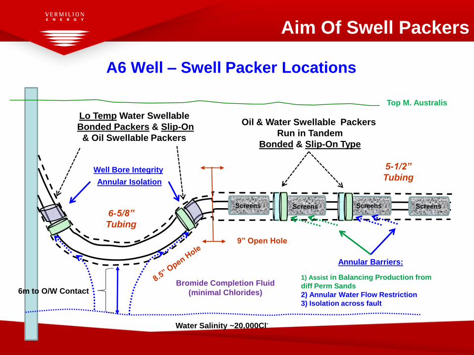
A6 Well – Swell Packer Locations
Screens Screens Screens Screens
Lo Temp Water Swellable
Bonded Packers & Slip-On
& Oil Swellable Packers
Oil & Water Swellable Packers
Run in Tandem
Bonded & Slip-On Type
Top M. Australis
6m to O/W Contact
Water Salinity ~20,000Cl-
Annular Isolation
Well Bore Integrity
Bromide Completion Fluid
(minimal Chlorides)
Annular Barriers:
1) Assist in Balancing Production from
diff Perm Sands
2) Annular Water Flow Restriction
3) Isolation across fault
6-5/8”
Tubing
5-1/2”
Tubing
9” Open Hole
Aim Of Swell Packers

FlexRite ICI Junction Assy
Installation of Lateral Screens & FlexRite Junction M/U & RIH with 5-1/2” screens and 6-5/8” blank pipe with FlexRite
bullnose.
M/U ReFlexRite junction and associated equipment (safety joint & swivel).
M/U inner string with 4 ¾” MWD
M/U screen hanger assembly, record MWD offsets, continue to RIH.
Orient ReFlexRite junction (lateral leg to HS) prior to landing using MWD
Sting into deflector, and set down weight to shear tag ring in deflector to
confirm on depth and landed.
Drop ball/dart to set screen hanger, pressure up and set screen hanger.
Swivel Safety Joint 6 5/8” XO & 5 ½” Lateral Screens
Mainbore Stinger Sealing in Deflector
9 5/8” x 7”
VCH Screen Hanger
Screen Hanger
RT, 4 ¾” MWD
Multilateral Installation

• Run Summary – Lower Completion
– B-12 Run #1:
• 7” Bullnose hung up on Deflector/Window
– B-12 Run #2:
• Modified Bullnose to 6.5” on Wandoo B Platform
• Dummy Run, no success
– B-12 Run #3:
• Modified Bullnose run through window at 70 ft/min, no drag
• Junction Run with Dual MWD and MFSM, added extra assembly
time: 6 hours on surface.
• Landed OK, saw pressure increase on depth. 1:40 to land.
Multilateral Installation

• Run Summary – Lower Completion
– B-8 Run:
• 7” Bullnose run through window at 45 - 70 ft/min, no drag
• Junction Run with Single MWD – 5 hours to handle all
assemblies*
• *Trouble with VCH and laid out V-Door.
• Landed OK, saw pressure increase on depth. 0:50 to land
– A-6 Run:
• Modified 7” Bullnose run through window, stood up once.
Rotated 180°, passed through with minimal drag.
• Junction Run with Single MWD – 3:10 to handle all assemblies.
• Landed OK, saw pressure increase and Ring Shear on depth.
0:30 to land
Multilateral Installation

9 5/8” x 7” VCH
Screen Hanger
Installation of Upper Completion
Run and install upper completion as per standard procedures.
Lateral Flow Path
Mainbore Flow Path
9 5/8” x 5-1/2” Production
Packer & Upper Completion
Multilateral Installation
Lateral Flow
Mainbore Flow
TRFC “Intelligent” Completion

Upper Completion Schematic “B” Well
TR-SSSV5½" Halliburton 'SP' w/ 4.75" RPT Nipple
GLV Side-Pocket Mandrel5½" SLB MMRG w/ 1 1/2" Orifice Valve
Tubing Hanger Cameron 5½" x 13 5/8" w/ 4.875" QXT profile
Comp
letion
Fluid =
Inhibit
ed ???
ppg K
Cl Brine
Open
MLT liner hanger
Packer9⅝"HES SFT 47-53.5# x 5½" , ID 4.872" Landing Nipple,
4½", Halliburton 4.562 XN, 4.455" No GoCrossover
5½" 15.5# JFE Bear to 4 1/2" 13.5# JFE Bear
Tubing5½" Range 3 JFE Bear
Sliding Sleeve4½", Halliburton XD w/ 3.688" 'R' profile
Landing Nipple4½” x 2.875" "X" profile
Interval Control Valve4½" SLB TRFC-HNB-AP
Landing Nipple4½” x "X", 2.812" Bore
Interval Control Valve4½" SLB TRFC HN-LP w/2.812 plug
Flush joint tubing4 1/2" 12.6# TD FJ
Seal Unit MLT Y PBRHalliburton ML 12.6# TD FJ (run with shroud)
Bell Guide4½" Halliburton MLT
Lower Completion
ML Hanger Packer
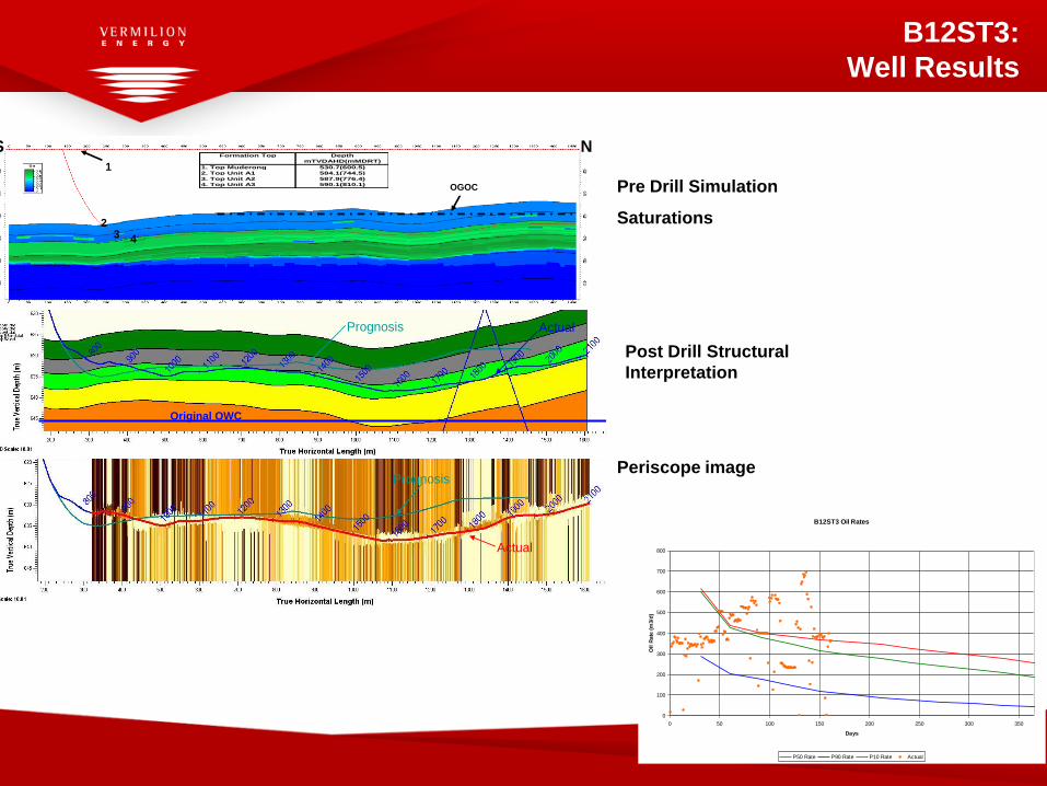
B12ST3:
Well Results
Formation Top Depth
mTVDAHD(mMDRT)
1. Top Muderong 530.7(600.5)
2. Top Unit A1 584.1(744.5)
3. Top Unit A2 587.9(776.4)
4. Top Unit A3 590.1(810.1)
S N
Distance along well (m)
23 4
OGOC
1
Formation Top Depth
mTVDAHD(mMDRT)
1. Top Muderong 530.7(600.5)
2. Top Unit A1 584.1(744.5)
3. Top Unit A2 587.9(776.4)
4. Top Unit A3 590.1(810.1)
S N
Distance along well (m)
23 4
OGOC
1
Original OWC
Prognosis Actual
Prognosis
Actual
Prognosis
Actual
Original OWC
Prognosis Actual
Prognosis
Actual
Prognosis
Actual
Original OWC
Prognosis Actual
Prognosis
Actual
Prognosis
Actual
Original OWC
Prognosis Actual
Prognosis
Actual
Prognosis
Actual
Pre Drill Simulation
Saturations
Post Drill Structural
Interpretation
Periscope image
B12ST3 Oil Rates
0
100
200
300
400
500
600
700
800
0 50 100 150 200 250 300 350
Days
Oil
Rate
(m
3/d
)
P50 Rate P90 Rate P10 Rate Actual
A1A2
A3B1
B2
C1
N S
Distance along well (m)
Dept
h (m
TVDA
HD)
A1
A2
A3
B1
B2
C1
6H/HST1
Expect water cone
200 m wide based on
reservoir simulation
3
45 B7
Expected GOC based
on reservoir
simulation
Depth
mTVDAHD(mMDRT)
1. Top Muderong 530.1(615.9)
2. Top Unit A1 579.6(763.0)
3. Top Unit A2 583.2(832 )
4. Top Unit A3 585.1(873)
5. Top B sand (Unit B1) (1) 588.1(1025)
6. Top B sand (Unit B1) (2) 589.5(1169)
Formation Top
2
6A1
A2
A3B1
B2
C1
N S
Distance along well (m)
Dept
h (m
TVDA
HD)
A1
A2
A3
B1
B2
C1
6H/HST1
Expect water cone
200 m wide based on
reservoir simulation
3
45 B7
Expected GOC based
on reservoir
simulation
Depth
mTVDAHD(mMDRT)
1. Top Muderong 530.1(615.9)
2. Top Unit A1 579.6(763.0)
3. Top Unit A2 583.2(832 )
4. Top Unit A3 585.1(873)
5. Top B sand (Unit B1) (1) 588.1(1025)
6. Top B sand (Unit B1) (2) 589.5(1169)
Formation Top
2
6
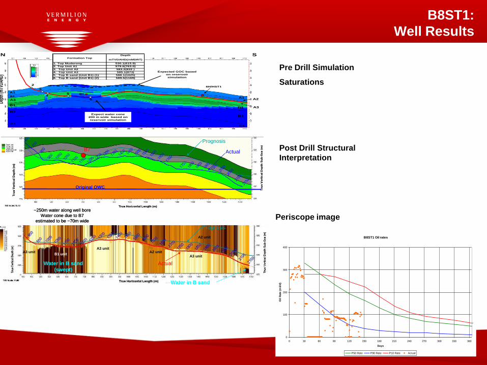
B8ST1:
Well Results
Original OWC
B7
Prognosis
Actual
Water in B sand
(swept)
~250m water along well bore
Water cone due to B7
estimated to be ~70m wide
Water in B sand
Prognosis
Actual
A3 unit
A3 unitA2 unit
A2 unit
A3 unitB1 unit
Original OWC
B7
Prognosis
Actual
Water in B sand
(swept)
~250m water along well bore
Water cone due to B7
estimated to be ~70m wide
Water in B sand
Prognosis
Actual
A3 unit
A3 unitA2 unit
A2 unit
A3 unitB1 unit
Pre Drill Simulation
Saturations
Post Drill Structural
Interpretation
Periscope image
B8ST1 Oil rates
0
100
200
300
400
0 30 60 90 120 150 180 210 240 270 300 330 360
Days
Oil
Rate
(m
3/d
)
P50 Rate P90 Rate P10 Rate Actual
South
Fault
A1
A2
A3B1
B2
C1
N S
Distance along well (m)
Dept
h (m
TVDA
HD)
A1A2
A3
B1
B2
C1
Expected GOC based
on reservoir
simulation
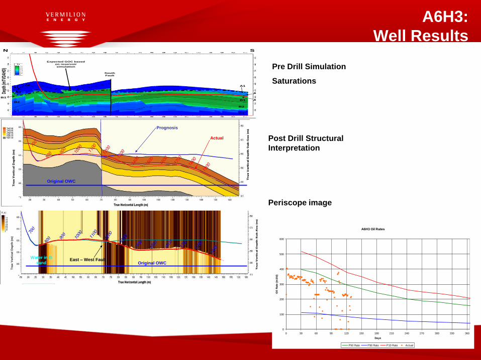
A6H3:
Well Results
Water in B
sand
Prognosis
Actual
East – West Fault
Original OWC
Original OWC
Water in B
sand
Prognosis
Actual
East – West Fault
Original OWC
Original OWC
Post Drill Structural
Interpretation
Periscope image
Pre Drill Simulation
Saturations
A6H3 Oil Rates
0
100
200
300
400
500
600
0 30 60 90 120 150 180 210 240 270 300 330 360
Days
Oil
Rate
(m
3/d
)
P50 Rate P90 Rate P10 Rate Actual
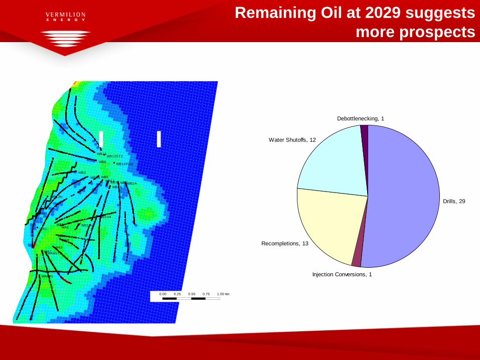
Remaining Oil at 2029 suggests
more prospects
WA1
WA2
WA3
WA4
WA5
WA6
WA6H1
WA7WA8ST1
WA9
WB10ig
WB11
WB12ST2
WB13H
WB14H
WB14Pilot
WB1A
WB2A
WB3
WB4A WB5
WB6
WB7
WB8A
WB9
439,000 440,000 441,000 442,000 443,000
439,000 440,000 441,000 442,000 443,000
7,7
72
,00
07
,77
3,0
00
7,7
74
,00
07
,77
5,0
00
7,7
72
,00
07
,77
3,0
00
7,7
74
,00
07
,77
5,0
00
0.00 0.25 0.50 0.75 1.00 km
File: Pred_A6B8B12Combined.irf
User: rjefferies
Date: 14/05/2010
Scale: 1:29870
Y/X: 1.00:1
Axis Units: m
0.0
0.7
1.3
2.0
2.7
3.4
4.0
4.7
5.4
6.0
6.7
A6B8B12Oil Per Unit Area - Total (m) 2029-12-31 K layer: 46
Drills, 29
Injection Conversions, 1
Recompletions, 13
Water Shutoffs, 12
Debottlenecking, 1

The Future for Wandoo
• Significant oil volumes will not be drained by current
completions.
• This trapped oil is in „small‟ reserve targets (Marginal
economics with conventional drilling).
• The team is focused on refining and testing alternative
methods to access „small‟ reserves targets incorporating
the lessons learned from the latest program.
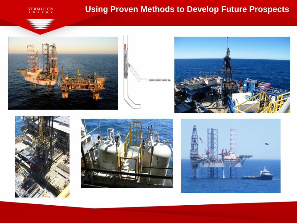
Using Proven Methods to Develop Future Prospects