multimedia – graphics and image representation dr. lina a. nimri lebanese university faculty of...
TRANSCRIPT

Multimedia – Graphics and Image Representation
Dr. Lina A. NimriLebanese UniversityFaculty of Economic Sciences and Business Administration 1st branch
Plan
•2D image display •Bitmap images / Vector images•Graphic file formats •BMP •GIF •PCX •PNG •TIF
Computer graphics
•The field of the IT concerning the creation and the handling of digital images is called computer graphics. ▫Computer graphics cover various areas of
knowledge, including the representation of graphic elements (text, image or video),
▫as well as their transformations (rotation, translation, zoom,…) by means of algorithms.

Display technology• Display process
▫ The image is shown on a screen (also called a monitor).
▫ This information comes from the computer, but in an “indirect” way. Indeed, the processor does not directly send information to the monitor, but processes the information coming from its Random Access Memory (RAM), then sends it to a graphics card that converts the information into electrical impulses, which it then sends to the monitor.
• Computer monitors▫ are usually cathode ray tubes (CRT), i.e. a tube
made out of glass in which an electron gun emits electrons which are then directed by a magnetic field towards a screen on which small phosphorescent elements (luminophores) are laid out, constituting points (pixels) that emit light when the electrons hit them.
The pixel concept
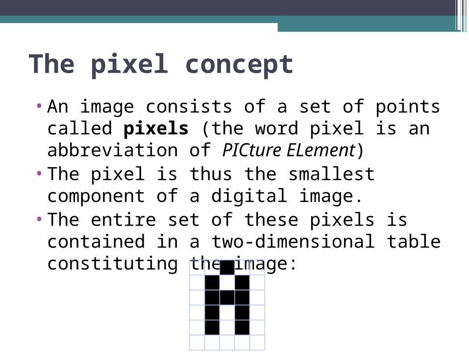
•An image consists of a set of points called pixels (the word pixel is an abbreviation of PICture ELement)
•The pixel is thus the smallest component of a digital image.
•The entire set of these pixels is contained in a two-dimensional table constituting the image:
Definition and resolution• Definition:
▫The number of points (pixels) constituting the image, that is, its “dimensions” (the number of columns of the image multiplied by its number of rows) is known as the definition.
• Resolution:▫A term often confused with the “definition”, is
determined by the number of points per unit of area, expressed in dots per inch (DPI), an inch being equivalent to 2.54 cm. The resolution thus makes it possible to establish the relationship between the number of pixels of an image and the actual size of its representation on a physical support.
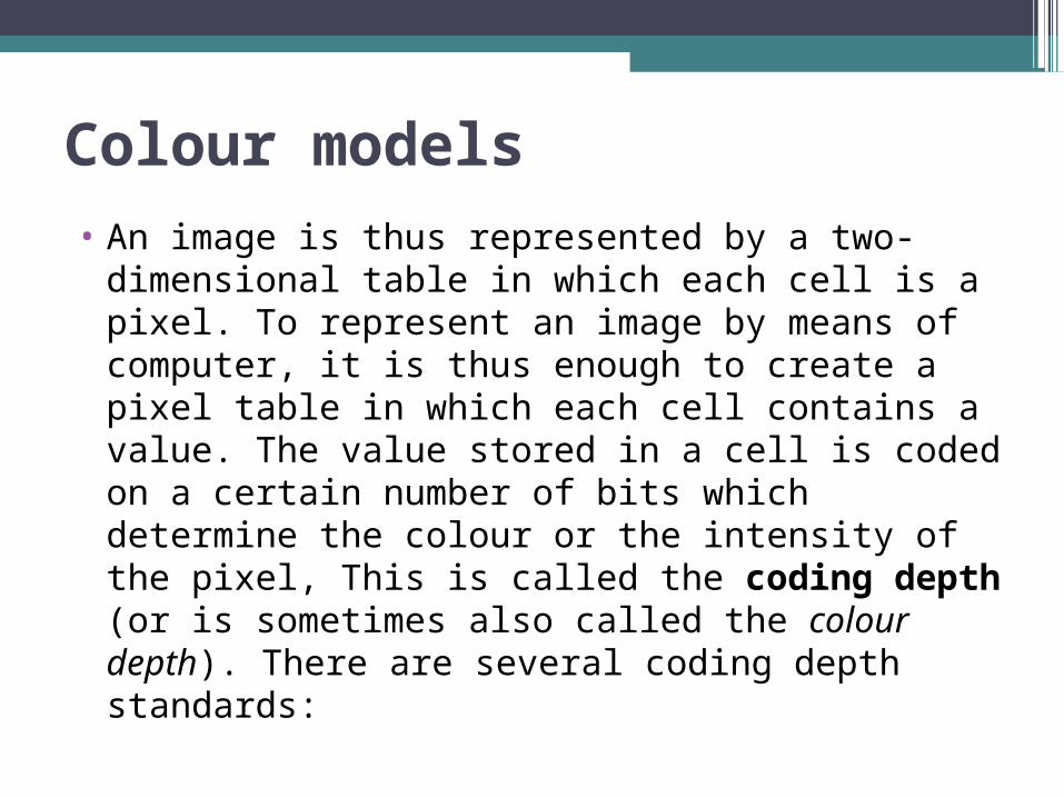
Colour models• An image is thus represented by a two-
dimensional table in which each cell is a pixel. To represent an image by means of computer, it is thus enough to create a pixel table in which each cell contains a value. The value stored in a cell is coded on a certain number of bits which determine the colour or the intensity of the pixel, This is called the coding depth (or is sometimes also called the colour depth). There are several coding depth standards:

Colour models• black and white bitmap: by storing one bit in
each cell, it is possible to define two colours (black or white).
• Bitmap with 16 colours or 16 levels of grey: storing 4 bits in each cell, it is possible to define 24 intensities for each pixel, that is, 16 degrees of grey ranging from black to white or 16 different colours.
• Bitmap with 256 colours or 256 levels of grey: by storing a byte in each cell, it is possible to define 28 intensities, that is, 256 degrees of grey ranging from black to white or 256 different colours.
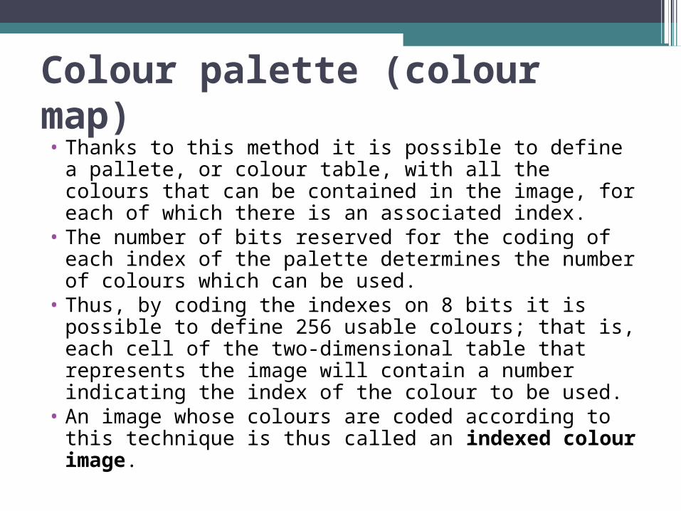
Colour palette (colour map)• Thanks to this method it is possible to define a
pallete, or colour table, with all the colours that can be contained in the image, for each of which there is an associated index.
• The number of bits reserved for the coding of each index of the palette determines the number of colours which can be used.
• Thus, by coding the indexes on 8 bits it is possible to define 256 usable colours; that is, each cell of the two-dimensional table that represents the image will contain a number indicating the index of the colour to be used.
• An image whose colours are coded according to this technique is thus called an indexed colour image.

True Colours
•"True Colours" or "real colours": this representation allows an image to be represented by defining each component (RGB, for red, green and blue). Each pixel is represented by a set comprising the three components, each one coded on a byte, that is, on the whole 24 bits (16 million colours). It is possible to add a fourth component, making it possible to add information regarding transparency or texture; each pixel is then coded on 32 bits.

Weight of an image• To know the weight (in bytes) of an image, it is
necessary to count the number of pixels that the image contains, which amounts to calculating the number of cells in the table , that is to say, the height of the table multiplied by its width. The weight of the image is thus equal to its number of pixels multiplied by the weight of each one of these elements.
• The following is the calculation for a 640x480 True Colour image: ▫Number of pixels: 640 x 480 = 307200 ▫Weight of each pixel:24 bits / 8 = 3 bytes ▫The weight of the image is thus equal to: 307200
x 3 = 921600 bytes 921600 / 1024 = 900 KB
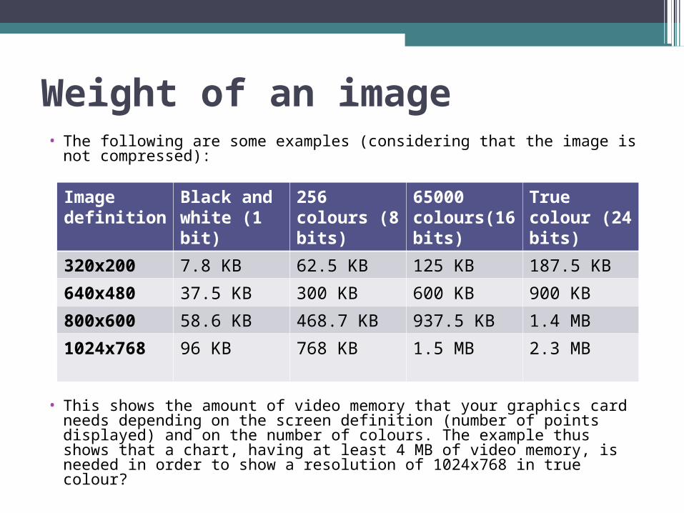
Weight of an image• The following are some examples (considering that the image is
not compressed):
• This shows the amount of video memory that your graphics card needs depending on the screen definition (number of points displayed) and on the number of colours. The example thus shows that a chart, having at least 4 MB of video memory, is needed in order to show a resolution of 1024x768 in true colour?
Image definition
Black and white (1 bit)
256 colours (8 bits)
65000 colours(16 bits)
True colour (24 bits)
320x200 7.8 KB 62.5 KB 125 KB 187.5 KB
640x480 37.5 KB 300 KB 600 KB 900 KB
800x600 58.6 KB 468.7 KB 937.5 KB 1.4 MB
1024x768 96 KB 768 KB 1.5 MB 2.3 MB
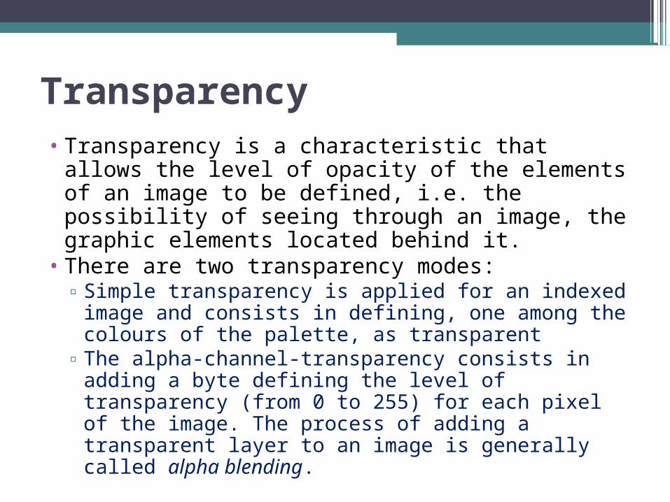
Transparency• Transparency is a characteristic that allows
the level of opacity of the elements of an image to be defined, i.e. the possibility of seeing through an image, the graphic elements located behind it.
• There are two transparency modes: ▫Simple transparency is applied for an indexed
image and consists in defining, one among the colours of the palette, as transparent
▫The alpha-channel-transparency consists in adding a byte defining the level of transparency (from 0 to 255) for each pixel of the image. The process of adding a transparent layer to an image is generally called alpha blending.

vector images and bitmap images• bitmap images (also called raster images):
these are pixeled images, i.e. a set of points (pixels) contained in a table, each of these points having one or more values describing its colour.
• vector images: vector images are representations of geometrical entities such as circles, rectangles or segments. ▫These are represented by mathematical
formulae (a rectangle is defined by two points, a circle by a centre and a radius, a curve by several points and an equation).
▫The processor will “translate” these forms into information that can be interpreted by the graphics card.
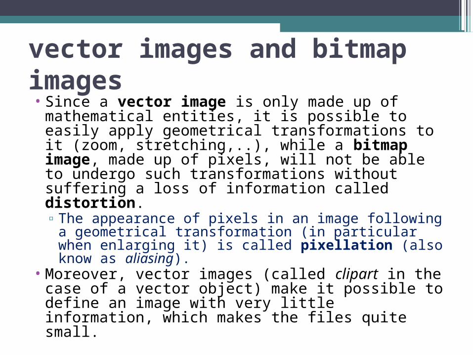
vector images and bitmap images• Since a vector image is only made up of
mathematical entities, it is possible to easily apply geometrical transformations to it (zoom, stretching,..), while a bitmap image, made up of pixels, will not be able to undergo such transformations without suffering a loss of information called distortion. ▫The appearance of pixels in an image following
a geometrical transformation (in particular when enlarging it) is called pixellation (also know as aliasing).
• Moreover, vector images (called clipart in the case of a vector object) make it possible to define an image with very little information, which makes the files quite small.
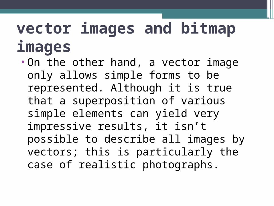
vector images and bitmap images•On the other hand, a vector image only
allows simple forms to be represented. Although it is true that a superposition of various simple elements can yield very impressive results, it isn’t possible to describe all images by vectors; this is particularly the case of realistic photographs.
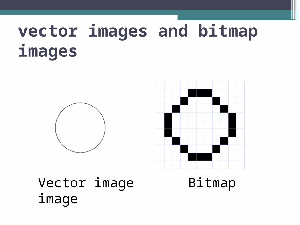
vector images and bitmap images
Vector image Bitmap image

vector images and bitmap images• The “vector” image above is just a
representation of what a vector image could resemble, because the quality of the image depends on the device used to make it visible to the eye. Your screen probably allows you to see this image with a resolution of at least 72 pixels per inch; the same file printed on a printer would offer a better image quality because it would be printed using at least 300 pixels per inch.
• Thanks to the technology developed by Macromedia and its software Macromedia Flash, or the SVG plug-in the vector format can be used on the Internet today.

1-bit Images•Each pixel is stored as a
single bit (0 or 1), so also referred to as binary image.
•Such an image is also called a 1-bit monochrome image since it contains no color.
•Example: “Lena” - by multimedia scientists | this is a standard image used to illustrate many algorithms).

8-bit Gray-level Images•Each pixel has a gray-value between 0 and
255. Each pixel is represented by a single byte; e.g., a dark pixel might have a value of 10, and a bright one might be 230.
• Bitmap: The two-dimensional array of pixel values that rep-resents the graphics/image data.
• Image resolution refers to the number of pixels in a digital image (higher resolution always yields better quality).▫Fairly high resolution for such an image might
be 1600 × 1200, whereas lower resolution might be 640 × 480.

8-bit Gray-level Images
•Frame buffer: Hardware used to store bitmap.▫Video card (actually a graphics card) is
used for this purpose.▫The resolution of the video card does not
have to match the desired resolution of the image, but if not enough video card memory is available then the data has to be shifted around in RAM for display.

Bit-planes for 8-bit grayscale image
8-bit image can be thought of as a set of 1-bit bit-planes, where each plane consists of a 1-bit representation of the image at higher and higher levels of "elevation": a bit is turned on if the image pixel has a nonzero value that is at or above that bit level.

8-bit grayscale levels
•Each pixel is usually stored as a byte (a value between 0 to 255), so a 640 × 480 grayscale image requires 300 kB of storage (640 × 480 = 307200).
The Lena image again, but this time in grayscale.

Image Data Types• The most common data types for graphics and
image file formats: 24-bit color and 8-bit color.• Some formats are restricted to particular
hardware/operating system platforms, while others are “cross-platform” formats.▫ Even if some formats are not cross-platform,
there are conversion applications that will recognize and translate formats from one system to another.
• Most image formats incorporate some variation of a compression technique due to the large storage size of image files.

24-bit Color Images
•The Lena image using 24-bit color

24-bit Color Images• In a color 24-bit image, each pixel is represented by
three bytes, usually representing RGB.▫ This format supports 256 × 256 × 256 possible combined
colors, or a total of 16,777,216 possible colors.▫ However such flexibility does result in a storage penalty:
A 640 × 480 24-bit color image would require 921.6 kB of storage without any compression.
• An important point: many 24-bit color images are actually stored as 32-bit images, with the extra byte of data for each pixel used to store an alpha value representing special effect information (e.g., transparency).
• next slide shows the image forestre.bmp, a 24-bit image in Microsoft Windows BMP format. Also shown are the grayscale images for just the Red, Green, and Blue channels, for this image.
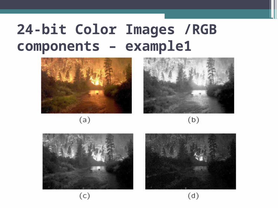
24-bit Color Images /RGB components – example1
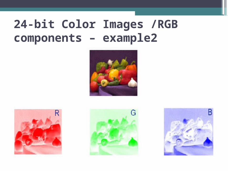
24-bit Color Images /RGB components – example2
8-bit Color Images
•Many systems can make use of 8 bits of color information (the so-called “256 colors”) in producing a screen image.
• Such image files use the concept of a lookup table to store color information.▫Basically, the image stores not color, but
instead just a set of bytes, each of which is actually an index into a table with 3-byte values that specify the color for a pixel with that lookup table index.
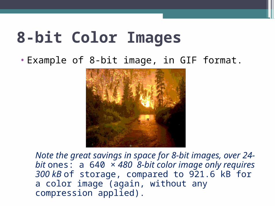
8-bit Color Images• Example of 8-bit image, in GIF format.
Note the great savings in space for 8-bit images, over 24-bit ones: a 640 × 480 8-bit color image only requires 300 kB of storage, compared to 921.6 kB for a color image (again, without any compression applied).
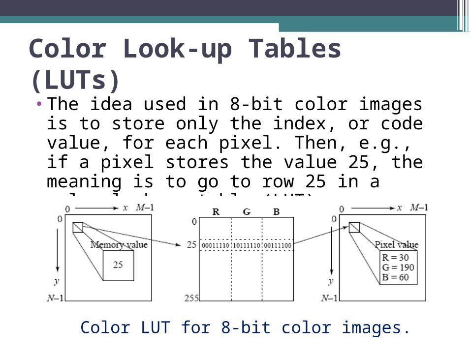
Color Look-up Tables (LUTs)•The idea used in 8-bit color images is to
store only the index, or code value, for each pixel. Then, e.g., if a pixel stores the value 25, the meaning is to go to row 25 in a color look-up table (LUT).
Color LUT for 8-bit color images.
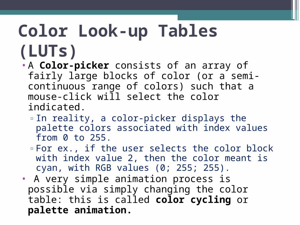
Color Look-up Tables (LUTs)•A Color-picker consists of an array of
fairly large blocks of color (or a semi-continuous range of colors) such that a mouse-click will select the color indicated.▫In reality, a color-picker displays the palette
colors associated with index values from 0 to 255.
▫For ex., if the user selects the color block with index value 2, then the color meant is cyan, with RGB values (0; 255; 255).
• A very simple animation process is possible via simply changing the color table: this is called color cycling or palette animation.

Color-picker for 8-bit color
•Each block of the color-picker corresponds to one row of the color LUT
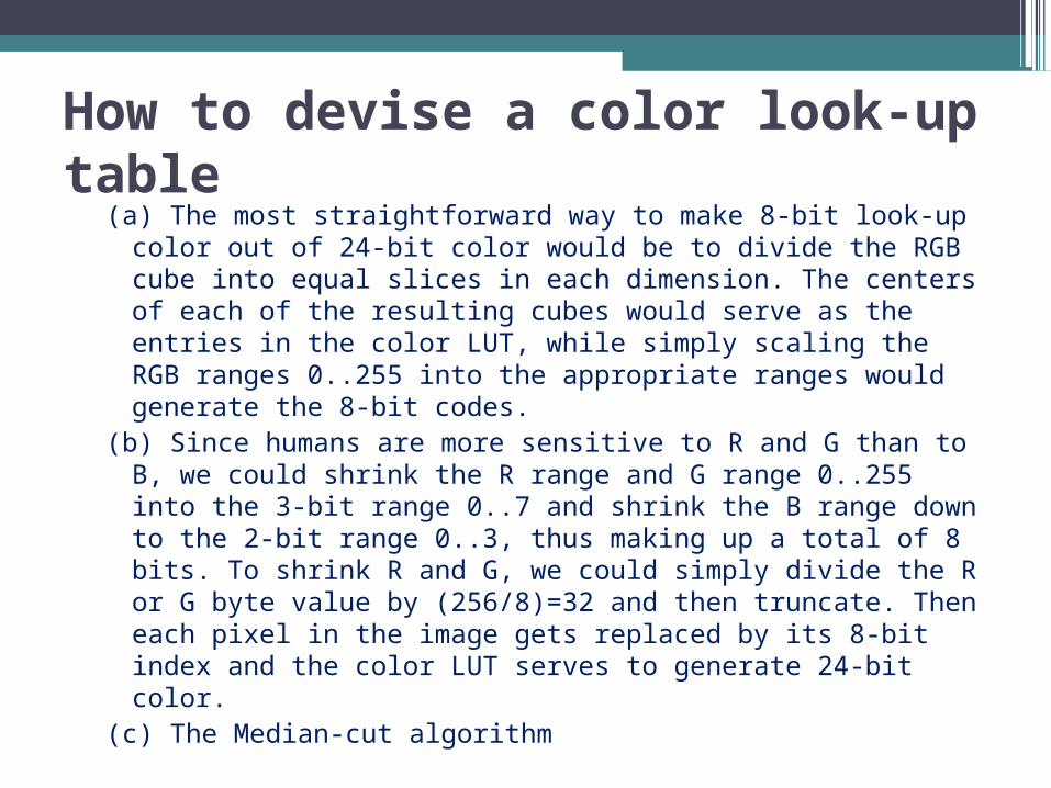
How to devise a color look-up table
(a) The most straightforward way to make 8-bit look-up color out of 24-bit color would be to divide the RGB cube into equal slices in each dimension. The centers of each of the resulting cubes would serve as the entries in the color LUT, while simply scaling the RGB ranges 0..255 into the appropriate ranges would generate the 8-bit codes.
(b) Since humans are more sensitive to R and G than to B, we could shrink the R range and G range 0..255 into the 3-bit range 0..7 and shrink the B range down to the 2-bit range 0..3, thus making up a total of 8 bits. To shrink R and G, we could simply divide the R or G byte value by (256/8)=32 and then truncate. Then each pixel in the image gets replaced by its 8-bit index and the color LUT serves to generate 24-bit color.
(c) The Median-cut algorithm

Median-cut algorithm• A simple alternate solution that does a better job
for this color reduction problem.(a) The idea is to sort the R byte values and find their
median; then values smaller than the median are labeled with a “0“ bit and values larger than the median are labeled with a “1” bit.
(b) This type of scheme will indeed concentrate bits where they most need to differentiate between high populations of close colors.
(c) One can most easily visualize finding the median by using a histogram showing counts at position 0..255.
• The median is the point where half the pixels are smaller and half are larger.
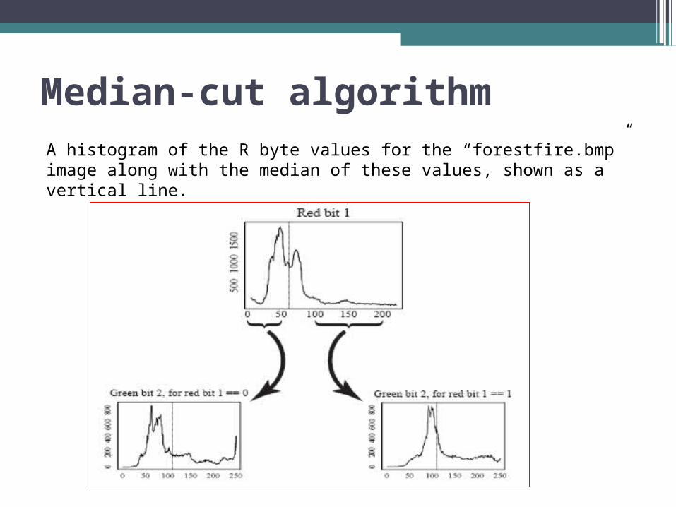
Median-cut algorithmA histogram of the R byte values for the “forestfire.bmp” image along with the median of these values, shown as a vertical line.

What is a file format?• We learned the way in which an image was
coded to be shown on a monitor, however, when we want to store an image in a file, this format is not the most practical? ▫ Indeed, we may want an image which takes
up less memory space, or an image which can be increased in size without causing pixelation.
• Thus, it is possible to store the image, describing it with an equation, in a file with a data structure, which will need to be decoded by the processor before the information is sent to the graphics card.
Types of file formats
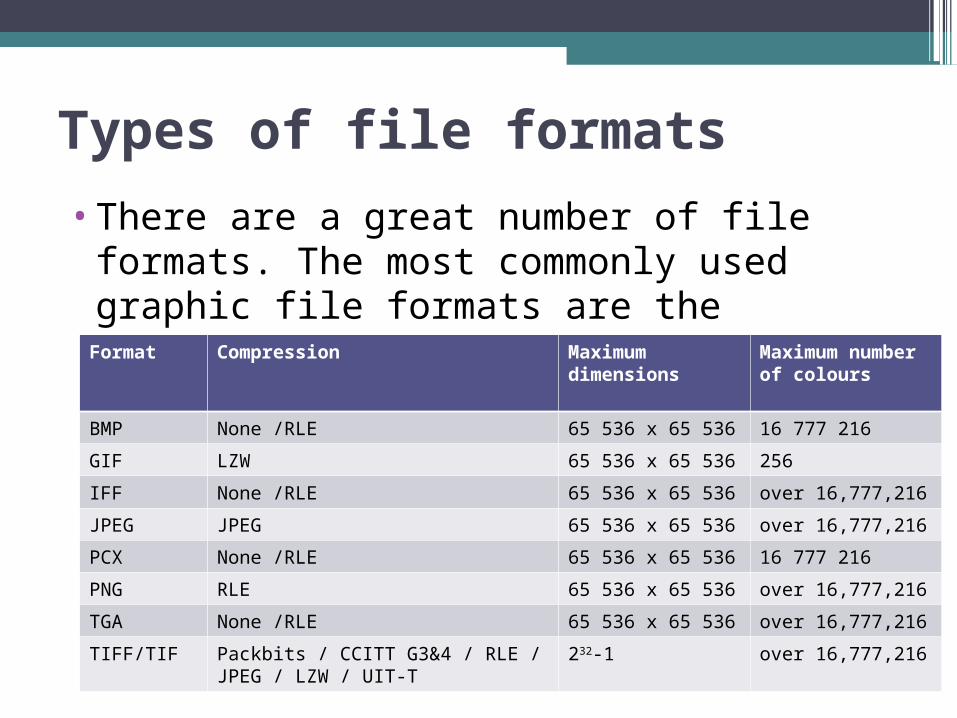
•There are a great number of file formats. The most commonly used graphic file formats are the following: Format Compression Maximum
dimensionsMaximum number of colours
BMP None /RLE 65 536 x 65 536 16 777 216
GIF LZW 65 536 x 65 536 256
IFF None /RLE 65 536 x 65 536 over 16,777,216
JPEG JPEG 65 536 x 65 536 over 16,777,216
PCX None /RLE 65 536 x 65 536 16 777 216
PNG RLE 65 536 x 65 536 over 16,777,216
TGA None /RLE 65 536 x 65 536 over 16,777,216
TIFF/TIF Packbits / CCITT G3&4 / RLE / JPEG / LZW / UIT-T
232-1 over 16,777,216

The BMP format•The BMP is one of the simplest formats. It
was jointly developed by Microsoft and IBM, which explains why it is particularly widespread on Windows and OS/2 platforms.
•A BMP file is a bitmap file, i.e. a graphic image file, with pixels stored in the form of point table and managing the colours either as true colours or using an indexed palette.
•The BMP format has been studied in such a way as to obtain a bitmap that is independent of the peripheral display device (DIB, Device independent bitmap).

The BMP formatThe structure of a bitmap file is the following: • File header: The file header provides
information on the type of file (Bitmap) and its size as well as indicating where information concerning the image actually starts.
• Bitmap information header: The bitmap information header provides information on the image, particularly its dimensions and its colours.
• Palette (optional) • The image body : The coding of the image is
done by successively writing the bits corresponding to each pixel, line by line, starting with the pixel in the bottom left-hand corner.
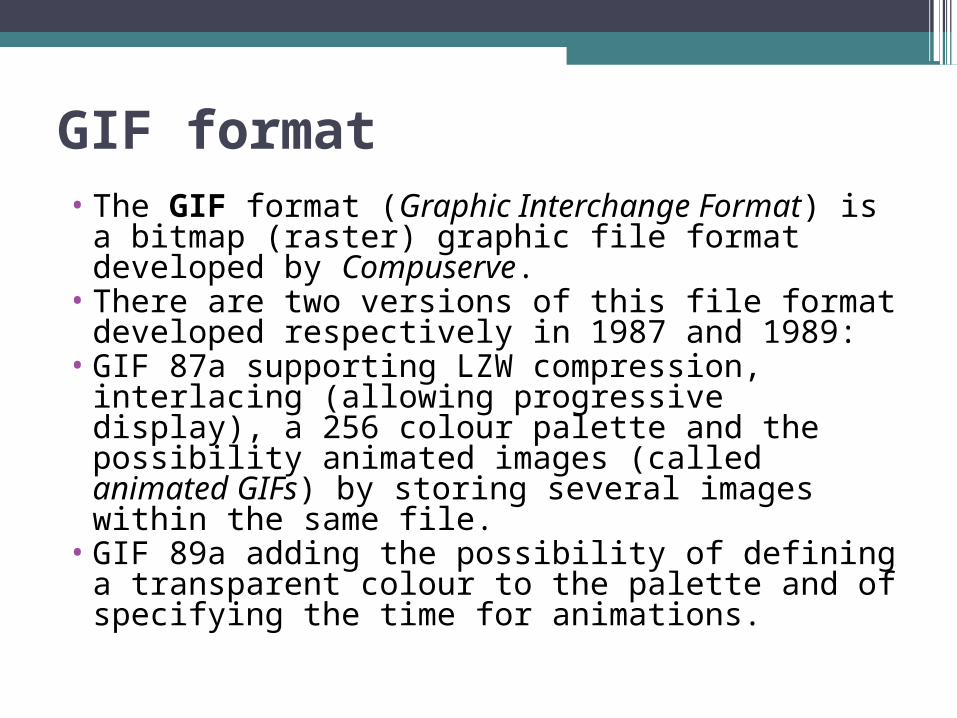
GIF format• The GIF format (Graphic Interchange
Format) is a bitmap (raster) graphic file format developed by Compuserve.
• There are two versions of this file format developed respectively in 1987 and 1989:
• GIF 87a supporting LZW compression, interlacing (allowing progressive display), a 256 colour palette and the possibility animated images (called animated GIFs) by storing several images within the same file.
• GIF 89a adding the possibility of defining a transparent colour to the palette and of specifying the time for animations.

Characteristics of the GIF format• A GIF image may contain between 2 and 256
colours (2, 4, 8, 16, 32, 64, 128 or 256) among 16.8 million in its palette. Thus, due to this palette with a limited number of colours (not limited in different colours), the images obtained by this format are generally very small in size.
• However, given the proprietary character of the LZW compression algorithm, all software publishers handling GIF images must pay a royalty to Unisys, the company that is the holder of the rights. This is one of the reasons why the PNG format is becoming increasingly more popular, to the detriment of the GIF format.

JPEG format• The acronym JPEG (Joint Photographic Expert Group)
comes from the meeting held in 1982 of a group of photographic experts, whose main concern was to work on the ways to transmit information (still or animated images). In 1986, the ITU-T developed compression methods intended for fax sending. These two groups joined to create a joint photographic experts group (JPEG).
• Unlike LZW compression, JPEG compression is a lossy, which affords it one of the best compression ratios, despite the slight loss of quality (20: 1 with 25:1 without any significant loss of quality).
• This compression method is much more effective for photographic images (comprising many different coloured pixels) than on geometrical images (unlike LZW compression) because the nuance differences due to compression are very visible in the latter

The stages of JPEG compression • Chrominance re-sampling, because the eye cannot
distinguish chrominance differences within a square of 2x2 points
• Image division into blocks of 8x8 points, then the application of the DCT function (Discrete Cosine Transform), which breaks up the image into a sum of frequencies
• Quantization of each block, i.e., a loss coefficient is applied (which makes it possible to determine the size/quality ratio) which will “cancel out” or decrease high frequency values, in order to attenuate the details by intelligently going over the block with RLE coding (in a zigzag pattern in order to remove as many zero values as possible).
• Image encoding then compression using the Huffman method

JPEG format• File formats that save a flow coded in JPEG
are actually called JFIF (JPEG File Interchange Format), but the term is usually deformed into “JPEG file".
• It should be noted that there is a lossless form of JPEG coding. Although little used by the data-processing community in general, it is used especially for the transmission of medical images in order to avoid confusing artifacts (purely dependent on the image and its digitalization) with real pathological signs. Compression is thus much less effective (only factor 2).

PNG format•The PNG format (Portable Network
Graphics or Ping format) is a bitmap (raster) graphic file format.
• It was developed in 1995 in order to provide a free alternative to the GIF format, which is a proprietary format whose rights are held by Unisys (proprietor of the LZW compression algorithm), to whom all software publishers using this type of format are under obligation to pay royalties. Thus, PNG is also a recursive acronym for PNG Not GIF.
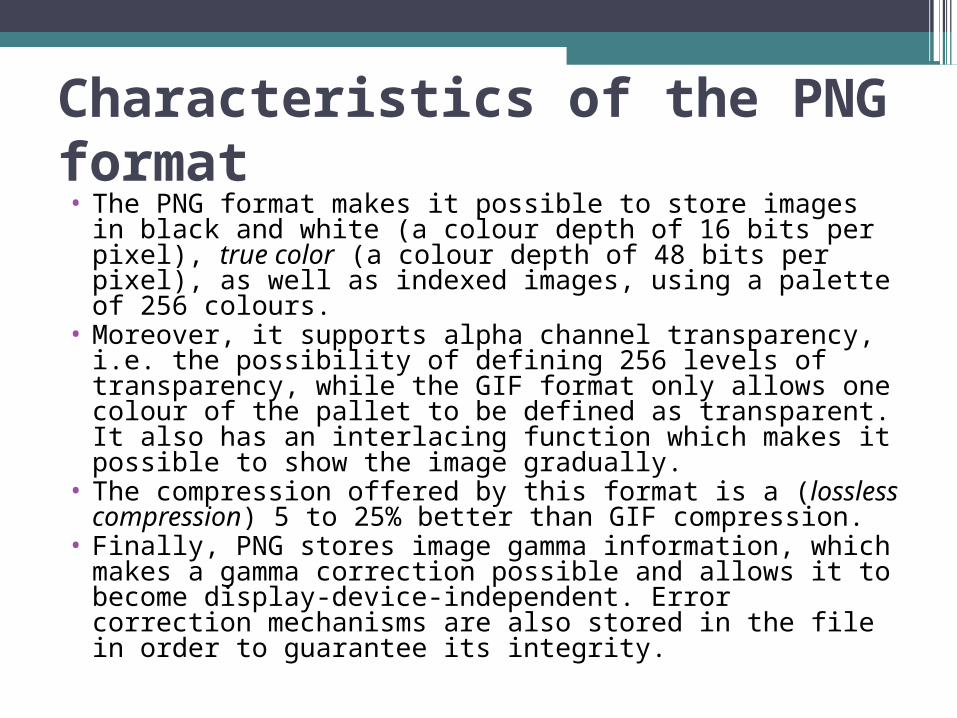
Characteristics of the PNG format• The PNG format makes it possible to store images in
black and white (a colour depth of 16 bits per pixel), true color (a colour depth of 48 bits per pixel), as well as indexed images, using a palette of 256 colours.
• Moreover, it supports alpha channel transparency, i.e. the possibility of defining 256 levels of transparency, while the GIF format only allows one colour of the pallet to be defined as transparent. It also has an interlacing function which makes it possible to show the image gradually.
• The compression offered by this format is a (lossless compression) 5 to 25% better than GIF compression.
• Finally, PNG stores image gamma information, which makes a gamma correction possible and allows it to become display-device-independent. Error correction mechanisms are also stored in the file in order to guarantee its integrity.

Structure of a PNG file• A PNG file comprises a signature, making it possible to
indicate that it is a PNG file, followed by a series of elements called chunks.
• The signature of a PNG file (in decimal notation) is the following: 137 80 78 71 13 10 26 10
• Each chunk comprises 4 parts : ▫ The size, a non-signed 4-byte integer, describing the size of the
chunk ▫ The chunk type: a 4-character (4-bytes) code comprised by
ASCII alphanumeric characters (A-Z, a-z, 65 to 90 and 97 to 122) allowing the nature of the chunk to be established
▫ The chunk data ▫ The CRC (cyclic redundancy check), a 4-byte correcting code
which allows the integrity of the chunk to be checked
• The chunks can be present in any order except that they must start with the header chunk (IHDR chunk) and finish with the end chunk (IEND chunk)

TIF format
The TIF format (Tagged Image File Format) is a bitmap (raster) graphic file format. It was developed in 1987 by Aldus (now belonging to Adobe). The latest specifications (Revision 6.0) were published in 1992.
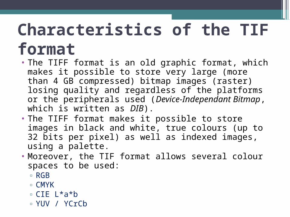
Characteristics of the TIF format• The TIFF format is an old graphic format, which
makes it possible to store very large (more than 4 GB compressed) bitmap images (raster) losing quality and regardless of the platforms or the peripherals used (Device-Independant Bitmap, which is written as DIB).
• The TIFF format makes it possible to store images in black and white, true colours (up to 32 bits per pixel) as well as indexed images, using a palette.
• Moreover, the TIF format allows several colour spaces to be used: ▫ RGB ▫ CMYK ▫ CIE L*a*b ▫ YUV / YCrCb

Structure of a TIFF file• The principle of the TIF format consists in defining
tags (hence the name Tagged Image File Format) describing the characteristics of the image.
• The tags make it possible to store information regarding the image dimensions, the number of colours used, the type of compression (many algorithms can thus be used: Packbits / CCITT G3&4 / RLE / JPEG / LZW / UIT-T), or the gamma correction.
• Thus, image description using tags makes software programming simple by making it possible to save in TIFF format.
• On the other hand, the amount of options is so vast, that many image readers supporting TIFF format do not integrate them all, so that it happens that an image saved using TIFF format may not be readable with another.