multiobjective optimization of rocket engine … oyama ohio aerospace institute, brook park, ohio...
TRANSCRIPT

Akira OyamaOhio Aerospace Institute, Brook Park, Ohio
Meng-Sing LiouGlenn Research Center, Cleveland, Ohio
Multiobjective Optimization of Rocket EnginePumps Using Evolutionary Algorithm
NASA/TM—2001-211082
August 2001
AIAA–2001–2581
https://ntrs.nasa.gov/search.jsp?R=20010094059 2019-05-17T16:24:09+00:00Z

The NASA STI Program Office . . . in Profile
Since its founding, NASA has been dedicated tothe advancement of aeronautics and spacescience. The NASA Scientific and TechnicalInformation (STI) Program Office plays a key partin helping NASA maintain this important role.
The NASA STI Program Office is operated byLangley Research Center, the Lead Center forNASA’s scientific and technical information. TheNASA STI Program Office provides access to theNASA STI Database, the largest collection ofaeronautical and space science STI in the world.The Program Office is also NASA’s institutionalmechanism for disseminating the results of itsresearch and development activities. These resultsare published by NASA in the NASA STI ReportSeries, which includes the following report types:
• TECHNICAL PUBLICATION. Reports ofcompleted research or a major significantphase of research that present the results ofNASA programs and include extensive dataor theoretical analysis. Includes compilationsof significant scientific and technical data andinformation deemed to be of continuingreference value. NASA’s counterpart of peer-reviewed formal professional papers buthas less stringent limitations on manuscriptlength and extent of graphic presentations.
• TECHNICAL MEMORANDUM. Scientificand technical findings that are preliminary orof specialized interest, e.g., quick releasereports, working papers, and bibliographiesthat contain minimal annotation. Does notcontain extensive analysis.
• CONTRACTOR REPORT. Scientific andtechnical findings by NASA-sponsoredcontractors and grantees.
• CONFERENCE PUBLICATION. Collectedpapers from scientific and technicalconferences, symposia, seminars, or othermeetings sponsored or cosponsored byNASA.
• SPECIAL PUBLICATION. Scientific,technical, or historical information fromNASA programs, projects, and missions,often concerned with subjects havingsubstantial public interest.
• TECHNICAL TRANSLATION. English-language translations of foreign scientificand technical material pertinent to NASA’smission.
Specialized services that complement the STIProgram Office’s diverse offerings includecreating custom thesauri, building customizeddata bases, organizing and publishing researchresults . . . even providing videos.
For more information about the NASA STIProgram Office, see the following:
• Access the NASA STI Program Home Pageat http://www.sti.nasa.gov
• E-mail your question via the Internet [email protected]
• Fax your question to the NASA AccessHelp Desk at 301–621–0134
• Telephone the NASA Access Help Desk at301–621–0390
• Write to: NASA Access Help Desk NASA Center for AeroSpace Information 7121 Standard Drive Hanover, MD 21076

August 2001
National Aeronautics andSpace Administration
Glenn Research Center
Prepared for the15th Computational Fluid Dynamics Conferencesponsored by the American Institute of Aeronautics and AstronauticsAnaheim, California, June 11–14, 2001
NASA/TM—2001-211082 AIAA–2001–2581
Akira OyamaOhio Aerospace Institute, Brook Park, Ohio
Meng-Sing LiouGlenn Research Center, Cleveland, Ohio
Multiobjective Optimization of Rocket EnginePumps Using Evolutionary Algorithm

Acknowledgments
The work was supported under the NASA’s ISE and RAC programs. The authors would like to thankDr. J. Veres of NASA Glenn Research Center for providing the pump code.
Available from
NASA Center for Aerospace Information7121 Standard DriveHanover, MD 21076
National Technical Information Service5285 Port Royal RoadSpringfield, VA 22100
Available electronically at http://gltrs.grc.nasa.gov/GLTRS

NASA/TM—2001-211082 1
MULTIOBJECTIVE OPTIMIZATION OF ROCKET ENGINE PUMPSUSING EVOLUTIONARY ALGORITHM
Akira OyamaOhio Aerospace InstituteCleveland, Ohio 44142
440–962–3148, [email protected]
Meng-Sing Liou1
National Aeronautics and Space AdministrationGlenn Research CenterCleveland, Ohio 44135
216–433–5855, [email protected]
ABSTRACTA design optimization method for turbopumps ofcryogenic rocket engines has been developed.Multiobjective Evolutionary Algorithm (MOEA) isused for multiobjective pump design optimizations.Performances of design candidates are evaluated byusing the meanline pump flow modeling method basedon the Euler turbine equation coupled with empiricalcorrelations for rotor efficiency.To demonstrate the feasibility of the present approach,a single stage centrifugal pump design and multistagepump design optimizations are presented. In bothcases, the present method obtains very reasonablePareto-optimal solutions that include some designsoutperforming the original design in total head whilereducing input power by 1%. Detailed observation ofthe design results also reveals some important designcriteria for turbopumps in cryogenic rocket engines.These results demonstrate the feasibility of the EA-based design optimization method in this field.
INTRODUCTIONWhile the budget for space development programs hasdrastically shrunk in most countries, recent and futurespace missions increasingly demand high performanceand reliable rocket engine systems and components,such as turbopumps. Progress in computational fluiddynamics (CFD) methods and development ofpowerful computational facilities have contributed tothe reduction in required cost and time to developadvanced turbopump designs. The design process stilllargely depends on experienced designers. Therefore,numerical design methods coupled with CFD, whichare capable of efficiently developing advancedturbopump designs, can greatly reduce suchdependency.
Among numerical optimization algorithms, gradient-based methods are long-standing and most widely usedapproaches1-3. These methods use the gradient of anobjective function with respect to changes in designvariables to calculate a search direction using steepestdescent, conjugate gradient, quasi Newton techniques,or adjoint formulations. The solution obtained by thesemethods will be a global optimum, only if the objectiveand constraints are differentiable and convex4.Unfortunately, the distribution of an objective functionof real-world design problems is usually multimodaland one could only hope for a local optimumneighboring the initial design point. Therefore, todetermine the global optimum, one must optimize froma number of initial points and check for consistency inthe optima obtained. In this sense, the gradient-basedmethods are not robust.Evolutionary Algorithms (EAs, for example, see [5])are emerging design optimization algorithms modeledon the mechanism of natural evolution. EAs searchfrom multiple points, instead of moving from a singlepoint. In addition, they require no derivatives orgradients of the objective function. These features leadto robustness and simplicity in coupling with anyevaluation codes. Parallel efficiency also becomes veryhigh by using a simple master-slave concept forfunction evaluations, if such evaluations consume mostof CPU time. Design optimization using CFD is atypical case. Application of EAs to multiobjectivedesign problems is also straightforward because EAsmaintain a population of design candidates in parallel.Due to these advantages, EAs are unique and attractiveapproach to real-world design optimization problems.Recently, EAs have been successfully applied toaerospace design optimization problems5-9.

NASA/TM—2001-211082 2
The objective of the present study is to develop anddemonstrate a design optimization method forturbopumps used in the cryogenic rocket engines. TheMultiobjective Evolutionary Algorithm (MOEA) willbe used for multiobjective optimization of pumpdesigns. Performances of design candidates will beevaluated by using the meanline pump flow modelingmethod based on the Euler turbine equation coupledwith empirical correlations for rotor efficiency. Presentapproach will be applied to centrifugal and multistageturbopump design optimization problems.
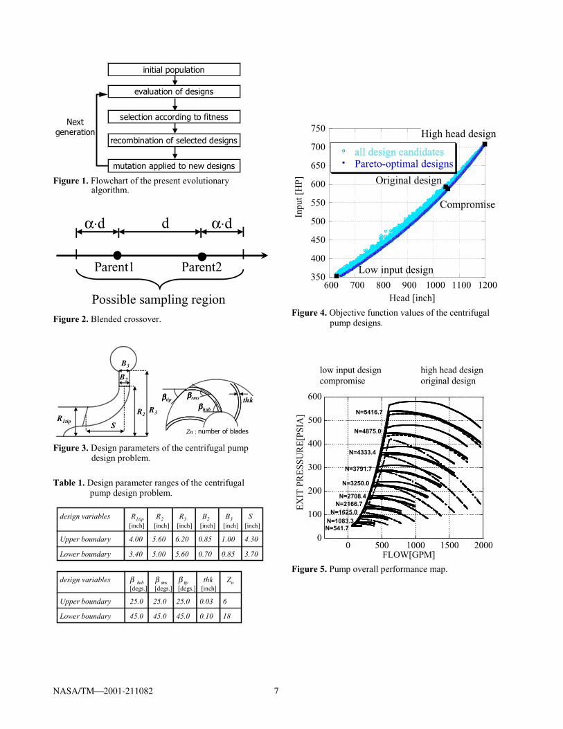
EVOLUTIONARY ALGORITHMSEAs mimic mechanism of natural evolution, where abiological population evolves over generations to adaptto an environment by selection according to fitness,recombination and mutation of genes (Fig.1). WhenEAs are applied to optimization problems, individual,fitness, and genes usually correspond to a designcandidate, an objective function value, and designvariables, respectively. One of the key features of EAsis that it searches from multiple points in the designspace, instead of moving from a single point likegradient-based methods do. Furthermore, thesemethods work on function evaluations alone and do notrequire derivatives or gradients of the objectivefunction. These features lead to the followingadvantages:1) Robustness: EAs have capability of finding a
global optimum, because they don’t use functiongradients that direct the search toward a localoptimum. In addition, EAs have capability tohandle any design problems that may involve non-differentiable objective function and/or a mix ofcontinuous, discrete, and integer designparameters.
2) Capability of sampling various Pareto-optimalsolutions in parallel: Real-world designoptimization problems typically involve multipleand often competing objectives. The solution tosuch problem is not a unique optimal solution, buta set of compromised solutions, largely known asPareto-optimal solutions. Each of those solutions isoptimal in the sense that no improvement can beachieved in one objective component that does notlead to degradation in at least one of the remainingcomponents. Therefore, primary goal of amultiobjective optimization problem is, unlike thatof a single objective optimization, to find variousPareto-optimal solutions to show the precisetradeoff information among the completingobjectives. By maintaining a population ofsolutions and introducing the concept of Pareto-optimality, EAs can uniformly sample variousPareto-optimal solutions in parallel.
3) Suitability to parallel computing: Since EAs arepopulation-based search algorithms, all designcandidates in each generation can be evaluated inparallel by using the simple master-slave concept.Parallel efficiency is also very high, if objectivefunction evaluations consume most of CPU time.
4) Simplicity in coupling evaluation codes: As thesemethods use only objective function values ofdesign candidates, EAs do not need substantialmodification or sophisticated interface toevaluation codes. If an all-out re-coding wererequired to every optimization problem like theadjoint methods, extensive validation of the newcode would be necessary every time. EAs can savesuch troubles.
The present MOEA uses floating-point representation,where an individual is characterized by a vector of realnumbers. It is natural to use the floating-pointrepresentation for real parameter optimizationproblems instead of binary representation because it isconceptually closest to the real design space, andmoreover, the string length is reduced to the number ofdesign variables. Fonseca’s Pareto-based rankingmethod10 is used for fitness assignment where anindividual’s rank corresponds to the number ofindividuals in the current population that are better thanthe corresponding individual in every objectivefunction. To maintain diversity in the population, astandard sharing function10 is incorporated. As theelitism, the best-N selection1 1 is incorporated, wherethe best N individuals are selected for the nextgeneration among N parents and N children based onPareto-optimality5 so that the Pareto-optimal solutionswill be kept once they are formed. Parents are selectedfrom the best N individuals randomly. To generate newdesign candidates from these parents, the blendedcrossover (BLX-a) is used, which is the most common
approach for recombination of two parents representedby a vector of real numbers proposed by Eshelman andSchaffer12. In this approach, children are generated on asegment defined by two parents, but the segment maybe extended equally on both sides determined by a userspecified parameter a. Thus, a child solution is
expressed as:
2)1(11 ParentParentChild ◊-+◊= gg (1)
21)1(2 ParentParentChild ◊+◊-= gg (2)where
g = ( 1 + 2a ) u - a (3)Child1, Child2 and Parent1, Parent2 denote designparameters of the children and parents, respectively. uis uniform random number in [0,1]. Schematic view ofBLX-a is shown in Fig. 2. When an EA is applied to a
design optimization problem, what is important isbalance of two conflicting goals: exploiting good
NASA/TM—2001-211082 3
solutions and exploring the search space13. Thus, BLX-0.5 is used in which both exploration and exploitationare carried out equally. Since the strong elitism is used,high mutation rate of 0.2 is applied and a randomdisturbance is added to the parameter in the amount upto ± 20% of the design space. Population size andmaximum number of generations are set to 100 and 90for the centrifugal pump design, 100 and 120 for themultistage pump design. Unbiased initial population isgenerated by randomly spreading solutions over theentire design space in consideration.
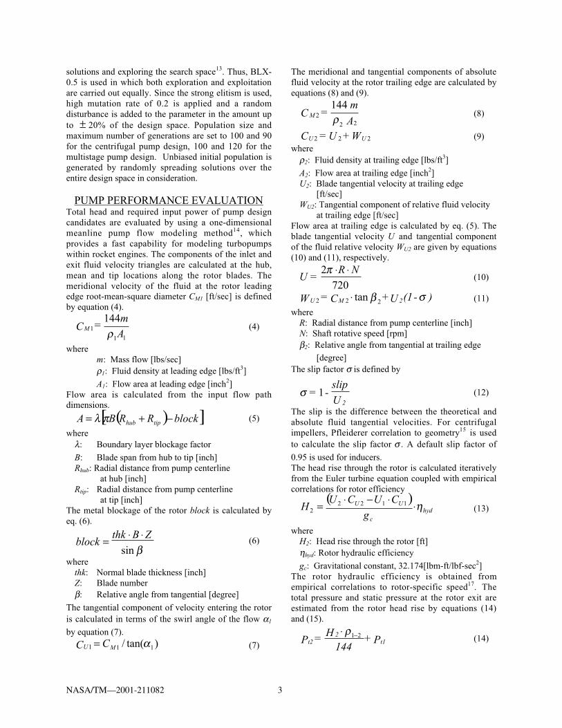
PUMP PERFORMANCE EVALUATIONTotal head and required input power of pump designcandidates are evaluated by using a one-dimensionalmeanline pump flow modeling method14, whichprovides a fast capability for modeling turbopumpswithin rocket engines. The components of the inlet andexit fluid velocity triangles are calculated at the hub,mean and tip locations along the rotor blades. Themeridional velocity of the fluid at the rotor leadingedge root-mean-square diameter CM1 [ft/sec] is definedby equation (4).
11
1144
Am
=CM r(4)
wherem: Mass flow [lbs/sec]r1: Fluid density at leading edge [lbs/ft3]
A1: Flow area at leading edge [inch2]Flow area is calculated from the input flow pathdimensions.
( )[ ]blockRRBA tiphub -+= pl (5)
wherel: Boundary layer blockage factor
B: Blade span from hub to tip [inch]Rhub: Radial distance from pump centerline
at hub [inch]Rtip: Radial distance from pump centerline
at tip [inch]The metal blockage of the rotor block is calculated byeq. (6).
bsin
ZBthkblock
◊◊= (6)
wherethk: Normal blade thickness [inch]Z: Blade numberb: Relative angle from tangential [degree]
The tangential component of velocity entering the rotoris calculated in terms of the swirl angle of the flow a1
by equation (7).)tan(/ 111 aMU CC = (7)
The meridional and tangential components of absolutefluid velocity at the rotor trailing edge are calculated byequations (8) and (9).
MC =m
A2
2 2
144r (8)
U UC = U +W2 2 2 (9)where
r2: Fluid density at trailing edge [lbs/ft3]
A2: Flow area at trailing edge [inch2]U2: Blade tangential velocity at trailing edge
[ft/sec]WU2: Tangential component of relative fluid velocity
at trailing edge [ft/sec]Flow area at trailing edge is calculated by eq. (5). Theblade tangential velocity U and tangential componentof the fluid relative velocity WU2 are given by equations(10) and (11), respectively.
7202 NR
=U◊◊p
(10)
)-(1U+C=W 2MU sb 222 tan◊ (11)
whereR: Radial distance from pump centerline [inch]N: Shaft rotative speed [rpm]b2: Relative angle from tangential at trailing edge
[degree]The slip factor s is defined by
s = -slip
U 21 (12)
The slip is the difference between the theoretical andabsolute fluid tangential velocities. For centrifugalimpellers, Pfleiderer correlation to geometry15 is usedto calculate the slip factor s . A default slip factor of
0.95 is used for inducers.The head rise through the rotor is calculated iterativelyfrom the Euler turbine equation coupled with empiricalcorrelations for rotor efficiency
( )hyd
c
UU
g
CUCUH h◊◊-◊= 1122
2 (13)
whereH2: Head rise through the rotor [ft]hhyd: Rotor hydraulic efficiency
gc: Gravitational constant, 32.174[lbm-ft/lbf-sec2]The rotor hydraulic efficiency is obtained fromempirical correlations to rotor-specific speed17. Thetotal pressure and static pressure at the rotor exit areestimated from the rotor head rise by equations (14)and (15).
P+144
H=P t12
t221-◊ r
(14)

NASA/TM—2001-211082 4
g1442
C-P=P
c
ts ◊◊◊ 2
22
22r
(15)
wherePt1: Total pressure at the leading edge [psia]Pt2: Total pressure at the trailing edge [psia]r1-2: Average density of the fluid from the leading
edge to the trailing edge [lbs/ft3]Ps2: Static pressure at the trailing edge [psia]
Fluid absolute velocity at trailing edge C2 [ft/sec] isdefined by
22
222 UM CCC += (16)
Total pressure at the discharge of the last stage Pt4
[psia] is given by the following equation
)( 224224 sttt PPPP -◊-= -w (17)
where the design point total pressure loss coefficient ofthe diffusion system is assumed to be known and isinput in terms of a normalized loss coefficient w2-4. The
total head rise through pump is calculated by
41
144
)(144
-
-◊=
rtt PP
H (18)
whereH4: Total head rise through pump[ft]Pt4: Total pressure at the pump exit [psia]r1-4: Average density of the fluid from the inlet
to the discharge [lbs/ft3]
The input power required to drive the rotor iscalculated from the head rise through the rotor, massflow, rotor hydraulic efficiency, mechanical efficiency,volumetric efficiency and disk pumping loss as
mechdisk
volhyd
PLHm
inputhhh
12 ◊˜˜¯
ˆÁÁË
Ê+
◊◊= (19)
whereinput: Input power [hp]hmech: Mechanical efficiency
hvol : Volumetric efficiency
PLdisk: Disk Pumping loss [hp]
The mechanical efficiency is assumed to be 0.98 andthe volumetric efficiency is based on internal leakagesand is expressed as the ratio of leakage to the inletflow. The disk pumping loss is calculated fromempirical correlations to geometry, fluid density atrotor trailing edge, and the shaft rotative speed16.During the calculation, local static pressure at the rotortip is compared to the local vapor pressure to check forthe cavitation inception point.To estimate off-design total head and required inputpower, the empirically derived variation of slip factorand rotor efficiency as a function of flow-speed ratio Fis used. Correction factor is also applied to the totalpressure loss coefficient of the diffusion system as afunction of loading parameter L.
32 0571508.0077472.06681688.0534988.1 FFFdesign
◊+◊+◊-=s
s(20)
32
,
029265.014086.03096.086387.0 FFFdesignhyd
hyd ◊-◊-◊+=h
h(21)
32 18765.08798.083527.18151.1 LLLdesign
◊+◊+◊-=w
w(22)
The loading parameter is defined in terms of the velocitiesat the vaneless diffuser exit and the velocity at thediffusion system throat.
23
23 MU
throat
CC
CL
+= (23)
whereCthroat: Fluid absolute velocity at the diffusion system
throat [ft/sec]CU3: Tangential component of fluid absolute velocity
at vaneless diffuser exit [ft/sec]CM3: Meridional component of fluid absolute
velocity at vaneless diffuser exit [ft/sec]
The velocity at the diffusion system throat is defined bythe equations (24) and (25).
A
m=CM
33
3144
r (24)
32
)1( 2323 RR
CC UU ◊◊-= -v (25)
where the pressure loss coefficient at the diffuser exit w2-3
is assumed to be 0.1. Fluid velocity at the throat is givenby the equation (26).
A
m=C
throat3
throat144
r (26)

NASA/TM—2001-211082 5
CENTRIFUGAL PUMP DESIGNFirst, redesign of a single-stage centrifugal pump, M-1oxygen scaled tester is demonstrated. Objectives of thepresent design problem are maximization of total head andminimization of input power at a design point. Theseobjectives are competing and therefore the solution to thisoptimization problem is Pareto-optimal solutions.The design point is shaft rotative speed of 5,416.7[rpm],total temperature of the fluid entering the pump of 545[Rankine], total pressure of the fluid entering the pump of50.0 [psia], and mass flow into the pump of 188.7[lbm/sec].Design parameters are rotor leading edge tip radius (Rtip1),rotor trailing edge radius (R2), volute tongue radius (R3),blade span at trailing edge (B2), blade span at volutetongue (B3), axial length of the blade at the root-mean-square diameter (S), number of blades (Zn), blade thickness(thk), blade trailing edge angle at the hub, root-mean-square radius, and tip (bhub , bmid , b tip) as shown in Fig. 3.
Table 1 presents present design spaces.Total head and input power of Pareto-optimal designs,original design, and all other design candidates areillustrated in Fig. 4. Designs that have cavitation areeliminated from the figure. Present Pareto-optimalsolutions successfully displays tradeoff informationbetween maximization of the total head and minimizationof the input power. Such tradeoff information is veryhelpful to a higher-level decision-maker in selecting adesign with other considerations. Among the Pareto-optimal solutions, some designs outperform the originaldesign in the total head while reducing the input power by1%.Figure 5 compares overall performance maps of theoriginal design, the highest total head design, the lowestinput power design, and a compromised design thatovercomes the original design in both objectives.Moreover, the compromised design is seen to improve theexit pressure in all off-design conditions. The designparameters of these designs are shown in Table 2.The absolute flow velocity at rotor exit hub is shown inFig. 6. This figure indicates the optimum designs havesmall exit flow velocity, which contributes to minimizingthe total pressure loss in the diffusion system. Byminimizing the total pressure loss in the diffusion system,designs can improve their total head rise. To minimize theexit flow velocity, the optimum designs have small slipfactor values, i.e., large slip than others. Actually, all threeoptimum designs in Table 2 have small axial length, whilethe high head design and the compromised designmaximize R2 to increase slip due to the inertial effect (Lowinput design minimize R2 to minimize input power). Thelow input design and the compromised design alsominimize their blade angle at hub and tip to reduceabsolute fluid velocity at rotor exit (the high head designmaximize blade trailing edge angles to improve its totalhead). However, it is known that non-uniform radial
velocity around the periphery of the impeller due to largeslip degrades its head rise. Therefore, this effect should becounted in the future study.Figure 7 shows the total pressure loss coefficient of thediffusion system of the designs. Pareto-optimal solutionssuccessfully minimize it to increase their total head rise.According to these detailed observations of the results,present MOEA obtained reasonable Pareto-optimalsolutions, which ensure the feasibility of the present designoptimization approach in rocket engine pump designs.
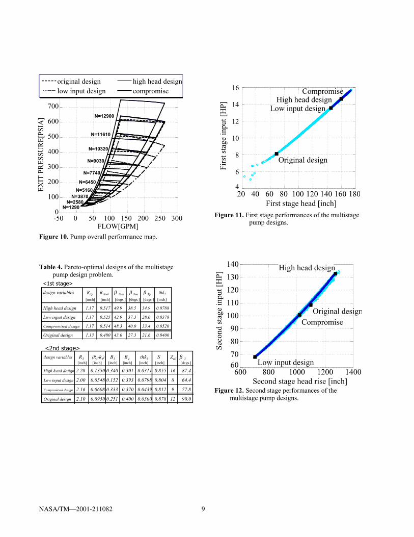
MULTISTAGE PUMP DESIGNNext, present design optimization method is applied to theredesign of RL10A-3-3A liquid oxygen pump consistingof one inducer and a single centrifugal impeller, followedby a vaneless diffuser and conical exit volute. Theobjectives are maximization of total head andminimization of input power at the design point, which isshaft rotative speed of 12,900[rpm], total temperature ofthe fluid entering the pump of 175 [Rankine], totalpressure of the fluid entering the pump of 40.0 [psia], andmass flow into the pump of 40.0 [lbm/sec]. Designparameters and the corresponding parameter ranges areshown in Fig. 8 and Table 3, respectively.Figure 9 shows total head and input power of Pareto-optimal designs, original design, and all other designcandidates that have no cavitation. Though this designoptimization problem involves two stages and a largenumber of design parameters, the present MOEA findsreasonable Pareto-optimal solutions including somedesigns that improve both total head and input power by asmuch as 1%.Figure 10 shows overall performance maps of the originaldesign and optimized designs. The compromised designimproves the exit pressure in all off-design conditions. Thedesign parameters of these designs are shown in Table 4.Figures 11 and 12 illustrate the head rise and the requiredinput power of the first and the second stages. Because theexit of the first stage connects with the inlet of the secondstage directly, the relation between the head rise and inputpower becomes linear. The optimum designs increase theirhead rise through the first stage because the slope of thecurve consisting of Pareto-optimal solutions in Fig. 12 issteeper than that of the line in Fig. 11. To increase the headrise through the first stage, the highest head design and thecompromised design increase Rtip, b 2hub, b2rms, and b2tip.
Another interesting thing is that the second stages of thePareto-optimal designs are not optimal by themselves,especially in the high head region. This is due to thenonlinear interactions between the first and the secondstages, which make a multistage pump design verydifficult.Figure 13 shows fluid velocity at rotor exit hub. ThePareto-optimal designs have a small fluid velocity at exitlike the single stage pump design. However, the optimumdesigns that have the total head of 950-1200 inches do not

NASA/TM—2001-211082 6
minimize their total head. This is probably due tocomplicated interactions between the first and secondstages.Figure 14 is the total pressure loss coefficient of thedesigns. This figure is also interesting because the optimaldesigns in low total head region minimize their totalpressure loss coefficient but the optimal designs in the hightotal head region maximize it. More work is necessary tounderstand the multistage pump designs.
SUMMARYIn the present study, a design optimization method forcryogenic rocket engine turbopumps has been developed.Multiobjective Evolutionary Algorithm is used for themultiobjective optimization of pump designs.Performances of design candidates are evaluated by usingthe meanline pump flow modeling method, which is basedon the Euler turbine equation coupled with empiricalcorrelations for rotor efficiency.To demonstrate the feasibility of the present approach,single stage centrifugal pump design and multistage pumpdesign optimizations are presented. In both cases, presentmethod obtains reasonable Pareto-optimal solutions thatinclude designs outperforming the original design in totalhead as well as input power by 1%. Detailed observationof the design results also reveals some important designpolicies in turbopump design of cryogenic rocket engines.These results ensure the feasibility of EA-based designoptimization method in this field.
REFERENCES[1] Hicks, R. M., Murman, E. M., and Vanderplaats, G.
N., “An Assessment of Airfoil Design by NumericalOptimization,” NASA TM X-3092, Ames ResearchCenter, Moffett Field, California, July 1974.
[2] Reuther, J., Cliff, S., Hicks, R., and van Dam, C. P.,“Practical Design Optimization of Wing/BodyConfigurations Using the Euler Equations,” AIAApaper 92-2633, 1992.
[3] Reuther, J., Jameson, A., Farmer, J., Martinelli, L.,and Saunders, D., “Aerodynamic Shape Optimizationof Complex Aircraft Configurations via an AdjointFormulation,” AIAA paper 96-0094, 1996.
[4] Vanderplaats, G. N., Numerical OptimizationTechniques for Engineering Design with applications,McGraw-Hill, Inc., New York, 1984.
[5] Quagliarella, D., Periauz, J., Poloni, C., and Winter G.(Eds.), Genetic Algorithms in Engineering andComputer Science, John Wiley and Sons, Chichester,1997.
[6] Powell, D. J., Tong, S. S. and Sholbick, M. M.,“EnGENEous Domain Independent, MachineLearning for Design Optimization,” Proceedings ofthe Third International Conference on GeneticAlgorithms, Morgan Kaufmann Publishers, Inc., SnaMateo, California, pp.151-159, 1989.
[7] Obayashi, S. and Takanashi, S., “GeneticOptimization of Target Pressure Distributions forInverse Design Methods, ” AIAA Journal, Vol. 34,No. 5, pp. 881-886, 1996.
[8] Oyama, A., “Multidisciplinary Optimization ofTransonic Wing Design Based on EvolutionaryAlgorithms Coupled with CFD solver,” EuropeanCongress on Computational Methods in AppliedSciences and Engineering, Barcelona, Spain,September 2000.
[9] Sasaki, D., Obayashi, S., Sawada, K. and Himeno, R.,“Multiobjective Aerodynamic Optimization ofSupersonic Wings Using Navier-Stokes Equations,”CD-ROM Proceedings of the ECCOMAS 2000, 2000.
[10] Fonseca, C. M. and Fleming, P. J., “Geneticalgorithms for multiobjective optimization:formulation, discussion and generalization”,Proceedings of the Fifth International Conference onGenetic Algorithms, Morgan Kaufmann Publishers,Inc., San Mateo, California, pp. 416-423, 1993.
[11] Tsutsui, S. and Fujimoto, Y., “Forking GeneticAlgorithms with blocking and shrinking modes(fGA),” Proceedings of the Fifth InternationalConference on Genetic Algorithms, MorganKaufmann Publishers, Inc., San Mateo, California,pp.206-213, 1993.
[12] Eshelman, L. J. and Schaffer, J. D., “Real-codedgenetic algorithms and interval schemata,”Foundations of Genetic Algorithm 2, MorganKaufmann Publishers, Inc., San Mateo, CA, pp.187-202, 1993.
[13] Booker, L. B., “Improving Search in GeneticAlgorithms,” Genetic Algorithms and SimulatedAnnealing, Morgan Kaufmann Publishers, Inc., SanMateo, CA, pp.61-73, 1987.
[14] Veres, J. P., “Centrifugal and Axial Pump Design andOff-Design Performance Prediction,” NASA TM106745, Lewis Research Center, Cleveland, Ohio,October 1994.
[15] Kovats, A., “Design and Performance of Centrifugaland Axial Flow Pumps and Compressors,”Macmillan, New York, 1964.
[16] Stepanoff, A. J., “Centrifugal and Axial Flow Pumps:Theory, Design, and Applications,” Wiley, NewYork, 1957.
NASA/TM2001-211082 7
initial population
evaluation of designs
selection according to fitness
recombination of selected designs
mutation applied to new designs
Nextgeneration
Figure 1. Flowchart of the present evolutionary
algorithm.
Parent2Parent1
α⋅d d α⋅d
Possible sampling region Figure 2. Blended crossover.
R2R3
R1tipS
B2
B3
thkββββtip
ββββhub
ββββrms
Zn : number of blades
Figure 3. Design parameters of the centrifugal pump design problem.
Table 1. Design parameter ranges of the centrifugal
pump design problem.
design variables R1tip R2 R3 B2 B3 S[inch] [inch] [inch] [inch] [inch] [inch]
Upper boundary 4.00 5.60 6.20 0.85 1.00 4.30
Lower boundary 3.40 5.00 5.60 0.70 0.85 3.70
design variables β hub β rms β tip thk Zn[degs.] [degs.] [degs.] [inch]
Upper boundary 25.0 25.0 25.0 0.03 6
Lower boundary 45.0 45.0 45.0 0.10 18
350
400
450
500
550
600
650
700
750
600 700 800 900 1000 1100 1200
all design candidatesPareto-optimal designs
Inpu
t [H
P]Head [inch]
Low input design
Compromise
High head design
Original design
Figure 4. Objective function values of the centrifugal
pump designs.
0
100
200
300
400
500
600
0 500 1000 1500 2000
low input designcompromise
high head designoriginal design
EX
IT P
RE
SSU
RE
[PSI
A]
FLOW[GPM]
N=5416.7
N=4875.0
N=4333.4
N=3791.7
N=3250.0
N=2708.4N=2166.7
N=1625.0N=1083.3N=541.7
Figure 5. Pump overall performance map.

NASA/TM2001-211082 8
Table 2. Pareto-optimal designs of the centrifugal pump design problem.
design variables R1tip R2 R3 B2 B3 S[inch] [inch] [inch] [inch] [inch] [inch]
High head design 3.50 5.60 6.05 0.846 0.871 3.74
Low input design 3.71 5.00 6.08 0.701 0.859 3.74
Compromised design 3.92 5.59 5.63 0.730 0.878 3.76
Original design 3.66 5.34 5.91 0.814 0.908 4.00
design variables β hub β rms β tip thk Zn[degs.] [degs.] [degs.] [inch]
High head design 44.9 36.0 44.6 0.100 18
Low input design 25.3 33.2 26.1 0.065 6
Compromised design 26.7 37.2 26.4 0.042 7
Original design 35.0 35.0 35.0 0.050 12
Figure 6. Flow velocity at second stage exit hub.
Figure 7. Total pressure loss coefficient of the centrifugal pump designs.
R2hub
R3
R1tip
S
B3
B4
ββββ2hub ββββ2rms ββββ2tip thk2
R4-R3
ββββ3 thk3 Zn3
Figure 8. Design parameters of the multistage pump design problem.
Table 3. Design parameter ranges of the multistage pump design problem.
design variables Rtip R2hub β 2hub β 2rms β 2tip thk2
[inch] [inch] [degs.] [degs.] [degs.] [inch]
Upper boundary 1.18 0.53 50.0 40.0 35.0 0.08
Lower boundary 1.08 0.43 35.0 25.0 20.0 0.03
<1st stage>
design variables R2 (R4-R3) B2 B3 thk3 S Zn3 β 3
[inch] [inch] [inch] [inch] [inch] [inch] [degs.]
Upper boundary 2.20 0.15 0.35 0.50 0.08 1.00 16 90.0
Lower boundary 2.00 0.05 0.15 0.30 0.03 0.80 8 60.0
<2nd stage>
Figure 9. Objective function values of the multistage pump designs.
0.3
0.35
0.4
0.45
0.5
0.55
0.6
0.65
600 700 800 900 1000 1100 1200 1300
Tot
al p
ress
ure
loss
coe
ffic
ient
head [inch]
Compromise
Original design
Low input design
120
140
160
180
200
220
240
260
600 700 800 900 1000110012001300
C2hu
b [f
t/sec
]
Head [inch]
Low input design
High head design
Original design
Compromise
80
90
100
110
120
130
140
150
160
800 900 1000 1100 1200 1300 1400 1500
all design candidatesPareto-optimal designs
Inpu
t [H
P]
Head [inch]
Compromise
Low input design
Original design
High head design
High head design
NASA/TM2001-211082 9
Figure 10. Pump overall performance map.
Table 4. Pareto-optimal designs of the multistage pump design problem.
design variables Rtip R2hub β 2hub β 2rms β 2tip thk2
[inch] [inch] [degs.] [degs.] [degs.] [inch]
High head design 1.17 0.517 49.9 38.5 34.9 0.0788
Low input design 1.17 0.525 42.9 37.3 28.0 0.0378
Compromised design 1.17 0.514 48.3 40.0 33.4 0.0520
Original design 1.13 0.480 43.0 27.3 21.6 0.0400
<1st stage>
design variables R3 (R4-R3) B3 B4 thk3 S Zn3 β 3[inch] [inch] [inch] [inch] [inch] [inch] [degs.]
High head design 2.20 0.1350 0.340 0.301 0.0311 0.855 16 87.4
Low input design 2.00 0.0548 0.152 0.393 0.0798 0.804 8 64.4
Compromised design 2.16 0.0608 0.333 0.370 0.0439 0.812 9 77.8
Original design 2.10 0.0950 0.251 0.400 0.0300 0.878 12 90.0
<2nd stage>
Figure 11. First stage performances of the multistage pump designs.
Figure 12. Second stage performances of the multistage pump designs.
0
100
200
300
400
500
600
700
800
-50 0 50 100 150 200 250 300
original designlow input design
high head designcompromise
EX
IT P
RE
SSU
RE
[PSI
A]
FLOW[GPM]
N=12900
N=11610
N=3870N=5160
N=6450
N=7740
N=9030
N=10320
N=1290N=2580
4
6
8
10
12
14
16
20 40 60 80 100 120 140 160 180
Firs
t sta
ge in
put [
HP]
First stage head [inch]
High head designCompromise
Low input design
Original design
6070
80
90
100
110
120
130
140
600 800 1000 1200 1400
Seco
nd s
tage
inpu
t [H
P]
Second stage head rise [inch]
Compromise
High head design
Low input design
Original design

NASA/TM2001-211082 10
Figure 13. Flow velocity at second stage exit hub.
Figure 14. Total pressure loss coefficient of the multistage pump designs.
140
160
180
200
220
240
260
800 900 100011001200130014001500
C3hu
b [f
t/sec
]
Total head [HP]
Low input design
High head design
Compromise
Original design
0.18
0.19
0.2
0.21
0.22
0.23
0.24
0.25
800 900 100011001200130014001500
W3-
4
Total head [inch]
High head designCompromise
Original design
Low input design
This publication is available from the NASA Center for AeroSpace Information, 301–621–0390.
REPORT DOCUMENTATION PAGE
2. REPORT DATE
19. SECURITY CLASSIFICATION OF ABSTRACT
18. SECURITY CLASSIFICATION OF THIS PAGE
Public reporting burden for this collection of information is estimated to average 1 hour per response, including the time for reviewing instructions, searching existing data sources,gathering and maintaining the data needed, and completing and reviewing the collection of information. Send comments regarding this burden estimate or any other aspect of thiscollection of information, including suggestions for reducing this burden, to Washington Headquarters Services, Directorate for Information Operations and Reports, 1215 JeffersonDavis Highway, Suite 1204, Arlington, VA 22202-4302, and to the Office of Management and Budget, Paperwork Reduction Project (0704-0188), Washington, DC 20503.
NSN 7540-01-280-5500 Standard Form 298 (Rev. 2-89)Prescribed by ANSI Std. Z39-18298-102
Form Approved
OMB No. 0704-0188
12b. DISTRIBUTION CODE
8. PERFORMING ORGANIZATION REPORT NUMBER
5. FUNDING NUMBERS
3. REPORT TYPE AND DATES COVERED
4. TITLE AND SUBTITLE
6. AUTHOR(S)
7. PERFORMING ORGANIZATION NAME(S) AND ADDRESS(ES)
11. SUPPLEMENTARY NOTES
12a. DISTRIBUTION/AVAILABILITY STATEMENT
13. ABSTRACT (Maximum 200 words)
14. SUBJECT TERMS
17. SECURITY CLASSIFICATION OF REPORT
16. PRICE CODE
15. NUMBER OF PAGES
20. LIMITATION OF ABSTRACT
Unclassified Unclassified
Technical Memorandum
Unclassified
National Aeronautics and Space AdministrationJohn H. Glenn Research Center at Lewis FieldCleveland, Ohio 44135–3191
1. AGENCY USE ONLY (Leave blank)
10. SPONSORING/MONITORING AGENCY REPORT NUMBER
9. SPONSORING/MONITORING AGENCY NAME(S) AND ADDRESS(ES)
National Aeronautics and Space AdministrationWashington, DC 20546–0001
Available electronically at http://gltrs.grc.nasa.gov/GLTRS
August 2001
NASA TM—2001-211082AIAA–2001–2581
E–12923
WU–708–87–13–00
16Multiobjective optimization; Evolutionary algorithm; Pumps
Unclassified -UnlimitedSubject Categories: 05 and 07 Distribution: Nonstandard
Prepared for the 15th Computational Fluid Dynamics Conference sponsored by the American Institute of Aeronautics andAstronautics, Anaheim, California, June 11–14, 2001. Akira Oyama, Ohio Aerospace Institute, 22800 Cedar Point Road,Brook Park, Ohio 44142; and Meng-Sing Liou, NASA Glenn Research Center. Responsible person, Meng-Sing Liou,organization code 5880, 216–433–5855.
Akira Oyama and Meng-Sing Liou
Multiobjective Optimization of Rocket EnginePumps Using Evolutionary Algorithm
A design optimization method for turbopumps of cryogenic rocket engines has been developed. Multiobjective Evolu-tionary Algorithm (MOEA) is used for multiobjective pump design optimizations. Performances of design candidates areevaluated by using the meanline pump flow modeling method based on the Euler turbine equation coupled with empiri-cal correlations for rotor efficiency. To demonstrate the feasibility of the present approach, a single stage centrifugalpump design and multistage pump design optimizations are presented. In both cases, the present method obtains veryreasonable Pareto-optimal solutions that include some designs outperforming the original design in total head whilereducing input power by 1 percent. Detailed observation of the design results also reveals some important design criteriafor turbopumps in cryogenic rocket engines. These results demonstrate the feasibility of the EA-based design optimiza-tion method in this field.