multiphasic construct studied in an ectopic osteochondral...
TRANSCRIPT

on October 5, 2018http://rsif.royalsocietypublishing.org/Downloaded from
rsif.royalsocietypublishing.org
ResearchCite this article: Jeon JE, Vaquette C,
Theodoropoulos C, Klein TJ, Hutmacher DW.
2014 Multiphasic construct studied in an
ectopic osteochondral defect model. J. R. Soc.
Interface 11: 20140184.
http://dx.doi.org/10.1098/rsif.2014.0184
Received: 21 February 2014
Accepted: 10 March 2014
Subject Areas:biomaterials, biomedical engineering
Keywords:multiphasic scaffold, biomaterials,
osteochondral repair, tissue engineering,
in vivo model
Author for correspondence:Dietmar W. Hutmacher
e-mail: [email protected]
& 2014 The Author(s) Published by the Royal Society. All rights reserved.
Multiphasic construct studied in anectopic osteochondral defect model
June E. Jeon, Cedryck Vaquette, Christina Theodoropoulos, Travis J. Kleinand Dietmar W. Hutmacher
Institute of Health and Biomedical Innovation, Queensland University of Technology, 60 Musk Avenue,Kelvin Grove, Queensland 4059, Australia
In vivo osteochondral defect models predominantly consist of small animals,
such as rabbits. Although they have an advantage of low cost and manageabil-
ity, their joints are smaller and more easily healed compared with larger
animals or humans. We hypothesized that osteochondral cores from large
animals can be implanted subcutaneously in rats to create an ectopic
osteochondral defect model for routine and high-throughput screening of mul-
tiphasic scaffold designs and/or tissue-engineered constructs (TECs). Bovine
osteochondral plugs with 4 mm diameter osteochondral defect were fitted
with novel multiphasic osteochondral grafts composed of chondrocyte-
seeded alginate gels and osteoblast-seeded polycaprolactone scaffolds, prior
to being implanted in rats subcutaneously with bone morphogenic protein-7.
After 12 weeks of in vivo implantation, histological and micro-computed tom-
ography analyses demonstrated that TECs are susceptible to mineralization.
Additionally, there was limited bone formation in the scaffold. These results
suggest that the current model requires optimization to facilitate robust bone
regeneration and vascular infiltration into the defect site. Taken together, this
study provides a proof-of-concept for a high-throughput osteochondral
defect model. With further optimization, the presented hybrid in vivo model
may address the growing need for a cost-effective way to screen osteochondral
repair strategies before moving to large animal preclinical trials.
1. IntroductionArticular cartilage is a unique tissue, which lacks vasculature, and has limited
self-healing ability. When left untreated, cartilage damage caused by trauma or
other degenerative conditions will not only cause pathological changes to the
surrounding cartilage, but also to the subchondral bone [1]. Osteochondral
lesions, which allow bone marrow infiltration into the damaged site, have
better regenerative capabilities but they often result in fibrocartilage with
inferior mechanical properties and diminished long-term durability. Current
treatment strategies for osteochondral lesions, such as joint debridement and
microfracture, have the disadvantage of fibrocartilage formation [2]. Osteochon-
dral autografts or mosaicplasty are also commonly used to treat osteochondral
defects and often have better outcomes, but these procedures have problems of
donor tissue availability, topology mismatch and donor site morbidity [3].
Autologous chondrocyte implantation (ACI) and matrix-associated ACI
(M-ACI) are some of the cell-based treatment methods that have shown positive
outcomes [4,5] but they also fall short of fully recapitulating the characteristics
of the native tissue [6].
In order to further improve current cell-based treatment methods, such as
ACI and M-ACI, the effects of combining other factors such as scaffolds
(cellular solids), matrices (hydrogels), growth factors and mechanical stimuli
are actively being investigated [7]. When combined with growth factors such
as TGF-b1, hydrogels such as alginate [8] and agarose [9] have been shown
to help chondrocytes maintain their spherical morphology while supporting
chondrogenic differentiation and cartilage-specific matrix deposition. Cartilage
constructs can also be mechanically stimulated in vitro to enhance chondrocyte
rsif.royalsocietypublishing.orgJ.R.Soc.Interface
11:20140184
2
on October 5, 2018http://rsif.royalsocietypublishing.org/Downloaded from
matrix synthesis and remodelling [10,11], and to recapitulate
zonal characteristics in the construct [12,13]. For bone tissue
engineering, polymeric and ceramic biomaterials are com-
monly used to design and fabricate scaffolds [14] with the
addition of osteogenic growth factors, such as bone morpho-
genic protein (rh-BMP)-2 or rh-BMP-7 and bone-forming cells
(e.g. osteoblasts) [15]. One of the most recent developments
in osteochondral tissue engineering is the emergence of not
only biphasic but multiphasic scaffolds [16]. By integrating
cartilage- and bone-specific matrices and scaffolds, which
are tailor-made to enhance chondrogenic or osteogenic devel-
opment of the construct, multiphasic tissue-engineering
approaches aim to enhance the integration and regenerative
potential of the engineered grafts.
With an increasing number of concepts emerging in
the cartilage and osteochondral tissue-engineering disciplines,
there is a growing need for high-throughput and cost-
effective in vivo animal models. Rabbits are commonly used
for osteochondral defect studies, but their joint scales are
much smaller than humans [17] (cartilage thickness: approx.
0.3 mm [18]), and osteochondral lesions in smaller animals,
such as rabbits, are known to have the tendency to heal
more readily compared with larger animals [19]. As a result,
treatment strategies developed using small animals may not
be as effective in larger animals, and there are obvious limit-
ations in interpreting and extrapolating treatment outcomes
from small-animal studies [20]. To this end, it is important
to scale up and use larger animal models with comparable
cartilage thickness and joint scale as humans for osteochon-
dral tissue-engineering studies [21]. However, large animal
models (e.g. porcine, dog or equine) are relatively expensive
and facilities that can accommodate them may not be readily
accessible, which make them less feasible in routine screening
of newly developed tissue-engineering strategies. To bridge
the gap of cost effectiveness by maintaining larger sample
size, accessibility and anatomical tissue scales, we hypo-
thesized that osteochondral cores from large animals, with
osteochondral defects, implanted subcutaneously in rats
would allow for screening of osteochondral repair potential
of multiphasic constructs.
2. Material and methods2.1. Chondrocyte and osteoblast isolation and cultureChondrocytes were isolated from macroscopically normal parts
of the cartilage from patients undergoing joint replacement surgeries
with ethical approval from Queensland University of Technology
and Prince Charles Hospital (n ¼ 3). Superficial (S) and middle-
deep (MD) zone chondrocytes were isolated, as described previously
[22]. This technique has been optimized in our laboratory and
involves manual dissection of the two layers using scalpel blades.
Diced S and MD cartilage pieces were digested overnight in 0.15%
collagenase type 2 (Worthington, Lakewood, NJ, USA) in serum-
free basal medium (LG-DMEM, 2 mM GlutaMax, 110 mg l21
sodium pyruvate, 50 U ml21 penicillin, 50 mg ml21 streptomycin).
All reagents were obtained from Invitrogen (CA, USA) unless
noted otherwise. Isolated chondrocytes were filtered through cell-
strainers (100 mm), washed using phosphate-buffered saline (PBS)
and seeded in T175 flasks at a density of 3000 cells cm22 for expan-
sion up to 1 passage (P1). Primary osteoblasts were isolated from the
bone chips collected from the macroscopically normal bone off-cuts
obtained from the joint replacement surgery patients. Bone chips
were washed 10 times by vigorous shaking in PBS and incubated
in 0.25% trypsin-EDTA for 30 min. After another wash in PBS,
bone chips were cultured in T175 flasks. Chondrocytes and osteo-
blasts from each patient were cultured separately using the basal
medium supplemented with 10% fetal bovine serum (FBS, Hyclone,
UT, USA), and media (15–20 ml) were changed twice a week. Once
confluent, cells were passaged using 0.1% trypsin-EDTA.
2.2. Chondrogenic differentiation of alginate discsseeded with surface or middle-deep chondrocytesand mechanical stimulation (cartilagecompartment)
After expansion, S and MD chondrocytes (P1) were resuspended
in 2% w/v alginate (Pronova UP LVG, FMC biopolymers, PA,
USA) solution at 107 cells ml21 and cross-linked using a
custom-made mould immersed in 102 mM CaCl2 bath [22].
Each S and MD construct was 4 mm and 1.5 mm in diameter
and thickness, respectively. Alginate discs were placed in
24-well plates and cultured in serum-free chondrogenic media
(HG-DMEM (Invitrogen), 1.25 mg ml21 bovine serum albumin,
1% ITS þ 1, 1027 M dexamethasone, 0.1 mM L-ascorbic acid (all
Sigma, USA) and 10 ng ml21 TGF-b3 (GroPrep Bioreagents, Ade-
laide, Australia)) for 12 weeks with media changed twice per
week (0.6 ml/construct). Following the 12-week culture, S and
MD alginate constructs were divided into either non-
compressed (NC) or compressed (Comp) groups. Constructs
selected for loading were subjected to a one-week intermittent
dynamic compression in a commercial unconfined compression
bioreactor (Cartigen C10–12c, Tissue Growth Technologies, Min-
netonka, MN, USA) while those in the NC group were cultured
under free-swelling conditions. The loading protocol was chosen
based on a previous optimization study for chondrocytes in algi-
nate gels [12] and consisted of 1 Hz sinusoidal compression for
3 h d21 at 50% compressive strain.
2.3. Biphasic construct fabrication, assembly andosteoblast seeding (bone compartment)
For the first layer, medical-grade polycaprolactone (PCL) was used
to fabricate a composite scaffold via fused deposition modelling
(FDM, Osteopore Inc., Singapore). The scaffolds measured 100 �100 � 6 mm3 and had 100% interconnectivity, 70% porosity and
a 08/908 lay-down pattern. For the second layer, medical-grade
PCL pellets (Lactel, USA) were loaded into a 2 ml syringe and
were electrospun using an in-house melt electrospinning device
(4 cm tip-to-collector distance, 808C, 20 ml h21, 7 kV) [23,24].
After 4 min of electrospinning, highly porous PCL melt-electro-
spun mesh with roughly 8 mm diameter was produced on top
of the aluminium foil-covered glass slides placed over the collector.
The biphasic scaffold was assembled as previously reported
[25,26]. Briefly, 6 mm long FDM scaffold cylinders were punched
out using a 4 mm biopsy punch and one side of the cylinder
was placed 1 cm from a hot plate heated to 3008C for 4 s and
then quickly press-fitted for 10 s onto the pre-cut PCL meshes
(4 mm diameter, approx. 1 mm thick). This heat treatment partially
melted the first layer of the FDM component enabling it to strongly
bind to the electrospun scaffold upon cooling and solidification.
Once the biphasic scaffolds were fused, they were soaked in 1 M
NaOH solution overnight to increase hydrophilicity. Biphasic scaf-
folds were then washed in 70% ethanol and put under UV for
20 min to sterilize and were left to dry in a sterile laminar hood
overnight. Once dry, biphasic scaffolds were placed in 24-well
plates and each scaffold was seeded with 2.5 � 105 osteoblasts
in 100 ml of basal media supplemented with 10% FBS. Cells
were allowed to adhere to the scaffold for 4 h in the incubator
before adding additional media (1.5 ml/construct). Scaffolds

electrospun
PCL scaffold
bovi
ne b
one
bovi
ne b
one
bovi
neca
rtila
ge
bovi
neca
rtila
ge
PCL-FDMscaffold
2%alginate
BMP-7
electrospun PCL meshS
MD2 mm
6 mm
1 mm
4 mm
(b)
(a)
(c) (d )
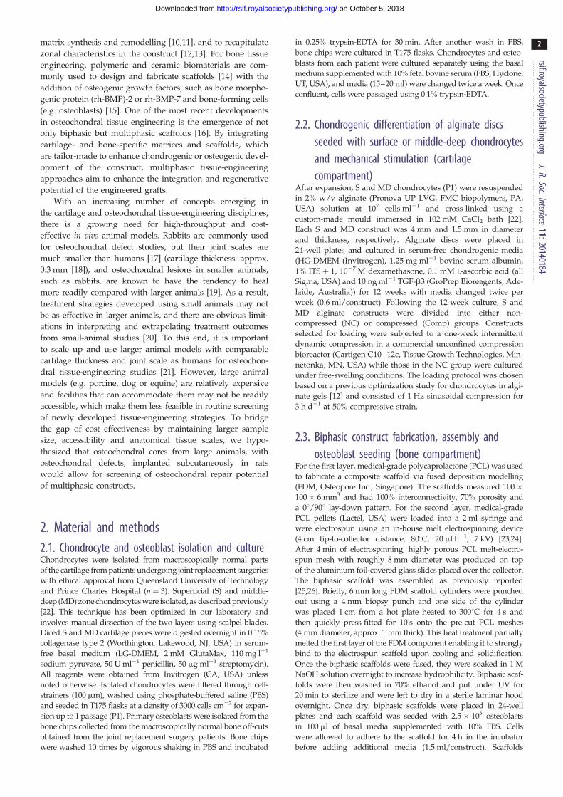
Figure 1. (a) Overview of the experimental design. Triphasic constructs were composed of chondrocyte-seeded bilayered (S, MD) 2% alginate gels and osteoblast-seeded PCL biphasic scaffolds. Alginate gels were cultured in chondrogenic media for 12 weeks and subjected to one week of compressive stimulation prior to in vivoimplantation. Triphasic constructs seeded with chondrocytes and osteoblasts were imaged using stereo microscopy, confocal microscopy (rhodamine – phalloidin(red), DAPI (blue)) and scanning electron microscopy (b) (scale bar, 1 mm). Prior to the rat subcutaneous implantation, osteochondral cores prepared frombovine knees were filled with triphasic constructs and the cartilaginous compartment was covered with electrospun PCL mesh (c) (scale bar, 6 mm). Osteochondralconstructs were implanted in rat subcutaneously in the dorsal pouches underneath the skin (d ) and allowed to mature for 12 weeks.
rsif.royalsocietypublishing.orgJ.R.Soc.Interface
11:20140184
3
on October 5, 2018http://rsif.royalsocietypublishing.org/Downloaded from
were cultured for 24 h prior to the final assembly into triphasic
osteochondral constructs.
2.4. Preparation of bovine osteochondral defects andtriphasic construct assembly
An adult bovine osteochondral joint was obtained from a local
abattoir. The joint was securely clamped on top of a surgical
bench and the joint capsule was opened using sterile scalpel
blade and surgical forceps. Osteochondral plugs of 6 mm in diam-
eter were cut from the patellofemoral groove using a sterile
trephine and a hacksaw. The tissue was constantly irrigated
with sterile PBS containing antibiotics to minimize heat-induced
damage. To create 4 mm diameter full thickness defects, osteo-
chondral plugs (n ¼ 32) were clamped down and were drilled in
the centre using a sterile trephine. The defect plugs were then cul-
tured in basal media containing 10% FBS for 3 days until the
triphasic construct insertion and rat subcutaneous implantation.
The triphasic construct was assembled 24 h prior to the
in vivo implantation using a modified protocol from a previous
study [22]. First, S and MD alginate discs (Comp or NC) were
placed on sterile filter paper soaked with 200 mM EDTA for 3 s
to partially de-cross-link one side on each disc. The de-cross-
linked sides were then pressed together for 10 s before being
transferred to a 102 mM CaCl2 bath for 10 min. To combine the
alginate constructs with the PCL biphasic scaffolds, the MD
side of the combined alginate was partially de-cross-linked
using 200 mM EDTA-soaked filter paper and was press-fitted
on top of the FDM side of the biphasic scaffold for 10 s to
allow alginate to partially infiltrate the pores of the PCL-FDM
scaffolds and were re-cross-linked in 102 mM CaCl2 bath. Com-
bined triphasic constructs were cultured in basal media
supplemented with 10% FBS for 24 h prior to combining with
the osteochondral defect plugs and being implanted in rat
subcutaneously. Cell-free alginates and biphasic PCL scaffolds
were also prepared using the same method, as controls.
2.5. Subcutaneous implantation of multiphasicconstructs in rat
Figure 1a depicts the global strategy conducted in this study,
which consisted of inserting a triphasic construct (figure 1b)
in a bovine osteochondral defect plug (figure 1c) prior to subcu-
taneous implantation in a rodent model (figure 1d ). Immediately
before the surgical implantation, triphasic constructs were taken
out of the media, gently dried using sterile gauze and inserted
into the bovine osteochondral defect plugs. 15 ml of recombinant
human bone morphogenic protein-7 (rhBMP-7, 1 mg ml21,
Olympus Biotech Corporation) mixed with 15 ml of fibrinogen
and 15 ml of thrombin (TISSEL, Baxter, IL, USA) was injected
into the bone compartment of the osteochondral defect. A thin
PCL electrospun membrane (less than 0.5 mm thick, 8 mm diam-
eter) was glued on top of the cartilage/alginate side using 5 ml of
fibrinogen and 5 ml of thrombin to give an added protection
against fibrous tissue infiltration into the cartilage compartment.
Bovine defect plugs containing the triphasic constructs and
rhBMP-7 were then implanted subcutaneously in athymic nude
rats. This experimental design did not consider the implantation
of osteoblast-seeded only (no rh-BMP-7) triphasic scaffolds as no
ectopic bone formation was expected in this group, as we have
recently demonstrated [27]. Animal ethics approval for the use
of rats in this experiment was granted by the Animal Ethics
Committee of Griffith University. Four 8-week-old male rats
(Animal Resources Centre, Canning Vale, WA, Australia) were
anaesthetized with isoflurane, and eight incisions were made
longitudinally along the central line of the shaved dorsal area,

rsif.royalsocietypublishing.org
4
on October 5, 2018http://rsif.royalsocietypublishing.org/Downloaded from
approximately 1.5 cm apart, and subcutaneous pockets were
made with a pair of surgical scissors. The assembled bovine
defect plugs were inserted individually in each subcutaneous
pocket. Rats were allowed to move freely within the cage and
were closely monitored throughout the experiment. Following
12 weeks of implantation, animals of all groups were sacrificed,
and the bovine defect plugs were fixed in 4% paraformaldehyde
(PFA) for 2 h. Fixed explants were incubated in a solution of
50 mM BaCl2 and 100 mM sodium cacodylate trihydrate over-
night to stabilize the remaining alginate gels and kept in 0.1%
sodium azide in PBS solution at 48C prior to further analysis.
J.R.Soc.Interface11:20140184
2.6. Analysis of glycosaminoglycan, DNA andmechanical properties of superficial andmiddle-deep alginate constructs
After 12 weeks of chondrogenic culture and one week of loading,
S and MD alginate constructs (NC and Comp) were analysed for
glycosaminoglycan (GAG) and DNA content (n ¼ 6), and also
compressive modulus (n ¼ 6). Prior to the biochemical assays,
S and MD constructs were digested in 0.5 mg ml21 proteinase
K solution (Invitrogen) overnight at 608C and thoroughly
mixed using the vortex. A modified 1,9-dimethylmethylene
blue (Sigma) assay at pH 1.5 [28] was used to determine GAG
content. DNA content in the S and MD constructs was quantified
using the Quant-iT PicoGreen dsDNA assay kit (Invitrogen)
according to the manufacturer’s protocol. The absorbance read-
ing from the GAG plate and the fluorescence reading from the
PicoGreen kit were measured on a POLARstar microplate
reader (BMG Labtech, Mornington, Australia). The compressive
moduli of the constructs were measured on an Instron 5848
microtester fitted with a 5 N load cell (Instron, Australia).
S and MD constructs were kept in media until immediately
before the compression test. The compression testing protocol
comprised a slow downward ramp (10 mm s21) from the contact
point (0.02 N) until 50% compressive strain level was reached.
The slope of the stress–strain curve in the 10–15% strain range
was used to calculate the compressive modulus.
2.7. Immunofluorescence staining of superficial andmiddle-deep constructs
In order to visualize the accumulation of collagen types I and II
following the long-term chondrogenic culture and loading, S and
MD alginate gels were immersed in a fixative solution containing
4% w/v PFA, 100 mM sodium cacodylate trihydrate (Sigma) and
10 mM CaCl2. To stabilize the alginate during the processing
steps, constructs were incubated at 48C overnight in 50 mM
BaCl2 solution containing 100 mM sodium cacodylate trihydrate.
Fixed constructs were paraffin-embedded and sectioned at 5 mm.
Once de-paraffinized and rehydrated, sections were soaked in
10 mM sodium citrate/0.05% Tween 20 buffer at pH 6.0 and
heated in a pressure cooker for 4 min at 948C. Heat-treated sec-
tions were further incubated with 0.1% w/v pronase and 0.1%
w/v hyaluronidase (all Sigma) solution at 378C for 30 min.
After the antigen retrieval process, sections were blocked with
2% FBS solution for 1 h and incubated overnight in primary
antibody solution for collagen type I (Col I, dilution 1 : 500,
I-8H5, MP Biomedicals, USA) and collagen type II (Col II,
dilution 1 : 200, II-II6B3, Developmental Studies Hybridoma Bank
(DSHB), USA). Sections were washed twice in PBS and incubated
in fluorescence-labelled goat anti-mouse secondary antibody
(Alexa Fluor 488, Invitrogen) for 1 h prior to mounting with Prolong
Gold (Invitrogen). After allowing the mounting media to dry in the
dark, sections were visualized using a fluorescence microscope
(Axio Imager A1, Zeiss, Jena, Germany).
2.8. Morphological analysis of the multiphasic scaffoldTriphasic constructs seeded with zonal chondrocytes (alginate)
and osteoblasts (biphasic PCL scaffold) were cultured in basal
medium supplemented with 10% FBS for one week prior to ima-
ging for morphological analysis (figure 1b). Triphasic constructs
were fixed in 4% PFA for 30 min and immersed in PBS/5 mM
CaCl2 solution to be imaged using the stereo microscope
(DMS1000, Leica, Australia). PFA-fixed constructs stained with
rhodamine–phalloidin and 40,6-diamidino-2-phenylindole
(DAPI) (all Invitrogen) in 5 mM CaCl2 in PBS solution were
imaged using a Nikon A1R confocal laser scanning microscope
system (Nikon Corp., Tokyo, Japan). Samples fixed in 3% glutar-
aldehyde in 0.1 M cacodylate buffer (pH 7.4) were imaged
without dehydration processes using Hitachi analytical table top
microscope TM3000 (Hitachi, Tokyo, Japan) operating at 5 kV.
2.9. Micro-computed tomographyOsteochondral explants were fixed in 4% PFA and stored in 0.1%
sodium azide in PBS at 48C prior to imaging. In order to visualize
the mineralized tissue, fixed osteochondral explants were scanned
in a mCT40 (Scanco Medical, Bruttisellen, Switzerland) at a
resolution of 12 mm, a voltage of 45 kVp and a current of
177 mA. The volume of newly formed bone within the bone com-
partment of the osteochondral construct was measured by the
micro-computed tomography (mCT) software using a greyscale
threshold of 220. For this experiment, the bovine bone was manu-
ally excluded for considering uniquely the newly formed bone
matrix (cell-free constructs: n ¼ 4; NC and Comp constructs: n ¼14). Three-dimensional images of the scaffolds were reconstructed
from the scans by the mCT system software package.
2.10. Equilibrium partitioning of an ionic contrastagent – micro-computed tomography
In order to visualize the GAG distribution in the cartilage and
alginate components of the explants, equilibrium partitioning
of an ionic contrast agent–mCT (EPIC-mCT) analysis was used,
according to the protocol described by Benders et al. [29].
Explants were incubated in 1 ml of ionic contrast agent solution
(40% ioxaglate (Hexabrix, Mallingckrodt, Hazelwood, MO,
USA)/60% PBS) for 16 h at 48C and scanned using mCT40
(Scanco Medical) at 45 kVp/177 mA. Scanned images were
analysed using Scanco mCT software (Scanco Medical).
Attenuation threshold levels were set between 1500 and 3500
Hounsfield units (HU) for all samples analysed. Gaussian filter
was used with Sigma of 1.2 and a support of 2. Three cross-
sectional images were taken at varying locations. As samples
immersed in the contrast agent may not be suitable for other ana-
lyses, EPIC-mCT was first performed using limited sample
numbers (n ¼ 2 per group). Based on the result of the first analy-
sis showing small differences between the groups, the rest of the
samples were allocated for other analysis.
2.11. Histological and immunohistochemical analysis ofosteochondral explants
Fixed osteochondral explants were decalcified in 5% formic acid
at room temperature for 14 days under constant agitation. Formic
acid was changed with fresh solution every other day. Following
the decalcification process, explants were embedded in paraffin
blocks and sectioned at 5 mm thickness. Haematoxylin and
eosin (H/E) staining was carried out using a Leica ST5010 Auto-
stainer (Leica Microsystems Pty Ltd, North Ryde, Australia).
Sections were also stained with 0.1% w/v Safranin-O for
10 min and counter stained with 0.05% w/v fast green and
Weigert’s iron haematoxylin for 5 and 10 min, respectively.
0.4
0.3
0.2
0.1
0S MD
S MD
S
** **
MD
12
8
4
0
200
150
100
50
0
DN
A (
mg)/
cons
truc
tG
AG
(mg
)/co
nstr
uct
E (
kPa)
S
MD
MD
S
NC
NC
NCCol II Col I
NC
Comp Comp
Comp Comp
NC
NC
Comp
NCComp
Comp
(b)
(c)
(d )
(a)
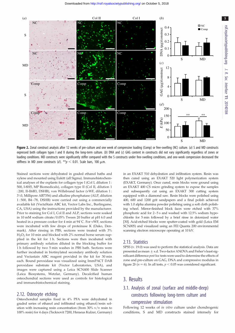
Figure 2. Zonal construct analysis after 12 weeks of pre-culture and one week of compressive loading (Comp) or free-swelling (NC) culture. (a) S and MD constructsexpressed both collagen types I and II during the long-term culture. (b) DNA and (c) GAG content in constructs did not vary significantly regardless of zones orloading conditions. MD constructs were significantly stiffer compared with the S constructs under free-swelling conditions, and one-week compression decreased thestiffness in MD zone constructs (d ). **p , 0.01. Scale bars, 100 mm.
rsif.royalsocietypublishing.orgJ.R.Soc.Interface
11:20140184
5
on October 5, 2018http://rsif.royalsocietypublishing.org/Downloaded from
Stained sections were dehydrated in graded ethanol baths and
xylene and mounted using Eukitt (all Sigma). Immunohistochem-
ical analyses of the explants for collagen type I (Col I, dilution 1 :
500, I-8H5, MP Biomedicals), collagen type II (Col II, dilution 1
: 200, II-II6B3, DSHB), von Willebrand factor (vWF, dilution 1 :
3\0, Millipore AB7356) and alkaline phosphatase (ALP, dilution
1 : 500, B4–78, DSHB) were carried out using a commercially
available kit (VectaStain ABC kit, Vector Labs Inc., Burlingame,
CA, USA) using the instructions provided by the manufacturer.
Prior to staining for Col I, Col II and ALP, sections were soaked
in 10 mM sodium citrate/0.05% Tween 20 buffer at pH 6.0 and
heated in a pressure cooker for 4 min at 948C. For vWF, sections
were incubated with few drops of proteinase K (Dako, Den-
mark). After rinsing in PBS, sections were treated with 3%
H2O2 for 10 min and blocked with 2% normal horse serum sup-
plied in the kit for 1 h. Sections were then incubated with
primary antibody solution diluted in the blocking buffer for
1 h followed by two 5 min washes in PBS bath. Sections were
further incubated in biotinylated secondary antibody solution
and Vectastain ABC reagent provided in the kit for 30 min
each. Bound peroxidase was visualized using ImmPACT DAB
peroxidase substrate kit (Vector Laboratories, USA), and
images were captured using a Leica SCN400 Slide Scanner
(Leica Biosystems, Wetzlar, Germany). Decalcified human
osteochondral sections were used as controls for histological
and immunohistochemical staining.
2.12. Osteocyte etchingOsteochondral samples fixed in 4% PFA were dehydrated in
graded series of ethanol and infiltrated using ethanol/resin sol-
ution with increasing resin concentration (from 30% v/v resin to
100% resin) for 4 days (Tecknovit 7200, Heraeus Kulzer, Germany)
in an EXAKT 510 dehydration and infiltration system. Resin was
then cured using an EXAKT 520 light polymerization system
(EXAKT, Germany). Once cured, resin blocks were ground using
an EXAKT 400 CS micro grinding system to expose the samples
and subsequently cut using an EXAKT 300 cutting system
equipped with a diamond saw. Resin blocks were polished using
400, 600 and 1200 grit sandpapers and a final polish achieved
with 1.0 alpha alumina powder polishing using a soft cloth polish-
ing wheel. Mirror-finished block faces were etched with 37%
phosphoric acid for 2–5 s and washed with 12.5% sodium hypo-
chlorite for 5 min followed by a brief rinse in deionized water
[30]. Acid-etched blocks were sputter-coated with gold (Leica EM
SCN005) and visualized using an FEI Quanta 200 environmental
scanning electron microscope operating at 10 kV.
2.13. StatisticsSPSS (v. 19.0) was used to perform the statistical analysis. Data are
presented as mean+ s.d. Two-factor ANOVA and Fisher’s least sig-
nificant difference post hoc tests were used to determine the effects of
zone and pre-culture on GAG, DNA and compressive modulus in
figure 2b (n ¼ 6). In all tests, p , 0.05 was considered significant.
3. Results3.1. Analysis of zonal (surface and middle-deep)
constructs following long-term culture andcompressive stimulation
Following 12 weeks of in vitro culture under chondrogenic
conditions, S and MD constructs stained intensely for

atte
nuat
ion
(HU
)
–1000 10 938(HU)
–1000 10 938(HU)
–1000 10 938(HU)
cell-free
compressed
non-compressed
3500
1500
(b)
(a)
(c)
Figure 3. EPIC-mCT images and histograms of attenuation in the cartilaginous compartments (dotted area) following in vivo implantation. Lower attenuation levelsindicate higher GAG content and high attenuation levels indicate bone or tissues with low GAG content. (a) Cell-free alginate gel, (b) alginate gel subjected to oneweek of compression and (c) non-loaded gel implanted within the cartilaginous compartment had similar attenuation levels between the different groups, anddepth-dependent zonal variations were not observed. Bone-like attenuation patterns were visible in the outer rims of the bovine cartilage in all explants.
rsif.royalsocietypublishing.orgJ.R.Soc.Interface
11:20140184
6
on October 5, 2018http://rsif.royalsocietypublishing.org/Downloaded from
collagen type II (Col II) around chondrocytes but limited
staining was observed in spaces further away from the cells
(figure 2a). Collagen type I (Col I) was also expressed in
some zonal chondrocytes and was less intense compared
with Col II. Both Col II and I stained similarly between
groups that were compressed for one week (Comp) and
those that were NC. DNA and GAG levels did not vary
significantly between groups regardless of zones or loading
conditions (figure 2b,c). Unconfined compression tests
revealed that MD constructs were significantly more stiff
compared with the S constructs under free-swelling con-
ditions (figure 2d; p ¼ 0.002). Compressive stimulation
decreased stiffness of MD constructs but not in S constructs
( p ¼ 0.009).
3.2. Triphasic scaffold assemblyAlginate discs seeded with surface and middle-deep
chondrocytes were well integrated, with visibly smooth tran-
sition line, as shown under the stereo microscope (figure 1b).
The PCL-FDM scaffold and the melt-electrospun PCL mesh
were also well integrated. Scanning electron microscopy
images show that top portions of the thin mesh filaments
are fused with the larger FDM scaffold fibres, which had
been partially melted by the heat treatment (figure 1b). The
interface between the zonal alginate construct and the PCL
scaffolds was relatively more fragile than the other interfaces,
yet was able to withstand manual handling using forceps.
Partial de-cross-linking of the alginate and press-fitting it
on top of the porous FDM scaffold resulted in alginate infil-
tration through the pores of the PCL scaffold and the
topmost layer of the PCL scaffold was partially encapsulated
in alginate gel (figure 1b). Fibrin glue used for the rh-BMP-7
delivery also served to hold the construct in place within the
osteochondral defect (figure 1c), and construct loosening did
not occur during the implantation procedures (figure 1d ).
3.3. Analysis of osteochondral constructs following invivo implantation: equilibrium partitioning of anionic contrast agent – micro-computed tomographyand micro-computed tomography
High degree of attenuation in the EPIC-mCT images has
been reported to show low GAG concentration in cartilage
[29]. The upper portion of the osseous compartment and
the inner parts of the cartilage compartment of the construct
had lower attenuation levels (figure 3). Zonal differences in
attenuation levels between the S and MD alginate layers
were not apparent. Attenuation level distributions were
also similar in cell-free (figure 3a) and cell-containing
alginate layers cultured with (figure 3b) or without com-
pression (figure 3c). The outer edge of the bovine
cartilage, along with the bovine bone had high attenuation
in the EPIC-mCT images, which is most likely owing to cal-
cification of the cartilage in these regions. This is apparent
from the three-dimensional mCT images of explants not
stained with Hexabrix, which show that the outer rims of
the bovine cartilage and the upper portion of the bovine
bone had substantial mineralization in most explants
(figure 4). Surprisingly, there was limited mineralization in
the PCL compartment with or without the pre-seeded osteo-
blasts (figure 4e) and no significance differences were found
between the groups (figure 4i).
3.4. Analysis of cartilage compartment: histology andimmunohistochemistry
The intensity of Safranin-O within the bovine tissue was the
strongest in the hypertrophic zone of the cartilage near the
bone and the newly mineralized regions on the outer edge
of the cartilage (figure 5a,b). These areas stained faintly of
collagen type II and had distinct boundaries (figure 5c,d ).

(b)
(a)
(c) (g)
(h)(d )
(e)
( f )
2.5
2.0
1.5
1.0
0.5
0
cell-free
compressed
non-compressed
bone
vol
ume
(mm
3 )
(i)
Figure 4. mCT images showing mineralized tissues in the scaffold. Explants of the triphasic scaffold inserted in bovine core, which had cell-free (osteoblast) (a,e) and osteo-blast-seeded bone compartments ( patient 1: b,f; patient 2: c,g; patient 3: d,h), had little bone formation in the osseous compartment. Explants that contained alginate gelssubjected to a one-week compressive loading prior implantation are shown in (e – h), and those that had non-loaded alginates are shown in (a – d ). Mineralization was visibleon the outer rims of the cartilage in all groups including the cell-free controls. (i) Bone volume within the bovine osteochondral defect as measured by mCT. There was nostatistical difference among the three groups (cell-free n¼ 4, Comp and NC n ¼ 14). (Online version in colour.)
rsif.royalsocietypublishing.orgJ.R.Soc.Interface
11:20140184
7
on October 5, 2018http://rsif.royalsocietypublishing.org/Downloaded from
Layered alginate constructs were largely intact in constructs
pre-seeded with cells compared with those that were cell-
free at the time of implantation (figure 6a– i). A thin line of
cells was found in some areas in between the S and MD
layers. Cells in the alginate appeared either as isolated
cells or were in large aggregates. Cell aggregates stained
faintly of collagen type II in the centre. Cell-free alginate
gels were fully infiltrated with fibrous tissues and many
multinucleated cells were found in between the alginate
debris (figure 6j–u).
3.5. Analysis of bone compartment: histology,immunohistochemistry and osteocyte etching
Sections stained for vWF indicated a limited blood vessel net-
work within the osseous construct while there were many

(b)(a) (c) (d )
bovinebone
bovinebone
bovinecartilagebovine
cartilage
triphasic construct triphasic construct
2m
m
2m
m
Figure 5. (a,b) Safranin-O and (c,d ) collagen type II-stained images of bovine cartilage tissue following in vivo implantation. Areas of the cartilage corresponding tothe mineralized regions are indicated by the open arrow. (b,d) Scale bars, 200 mm. (Online version in colour.)
rsif.royalsocietypublishing.orgJ.R.Soc.Interface
11:20140184
8
on October 5, 2018http://rsif.royalsocietypublishing.org/Downloaded from
blood vessels found within the bovine bone (figure 7a,b, black
arrowheads). Scanning electron micrographs of acid-etched
explants also show that osteocytes within the bovine bone had
well-preserved processes, which were extensively interconnected
with each other (figure 7c,d, black arrowheads) although those
within approximately 100 mm of inner and outer edges of the
bone had relatively diminished interconnectivity and some
empty lacunae, possibly from heat or mechanically induced
cell injury during the osteochondral plug preparation. The
upper regions of the bovine bone, which were also densely
mineralized according to the mCT analysis, had numerous
patches, which stained strongly with Safranin-O (figure 7e,white arrowheads). These regions of bone also contained many
cells, which stained positive for ALP, as indicated by the black
arrowhead in figure 7f. Lower parts of the bone also exhibited
Safranin-O (figure 7g, white arrowheads)-stained regions and
ALP-positive cells (figure 7h, black arrowhead), but to a lesser
degree. Although the fibrous interstitial tissue stained intensively
for ALP in both the top and bottom portion of the bovine osteo-
chondral plug (figure 7f,h), there was a clear difference within the
bovine bone with the top portion having a large number of ALP-
positive stained cells as opposed to the bottom portion where
only a very few cells were positively stained.
3.6. Fibrous tissue infiltrationFibrous tissue infiltration occurred throughout the osteochondral
explants in all samples. In the bovine cartilage, fibrous tissues
were found to penetrate towards the periphery of the mineraliz-
ing areas (figure 8a,b,e,f,i,j) from the both outer and inner edge
of the bovine cartilage. Fibrous tissue infiltration also occurred
from the top portion of the cartilage and immediately below
the mineralized regions (figure 8c,g,k). Rat fibroblasts also satu-
rated the electrospun mesh and formed a cellular bridge
between the mesh and cartilage (figure 8c,g,k). Fibrous tissues
fully surrounded the PCL-FDM/melt-electrospun scaffold in
the osseous compartment, and they were also present throughout
the bovine bone (figure 8d,h,l ). Macrophage-like multinucleated
cells were visible in some areas of the fibrous tissue, which may
indicate inflammatory responses.
4. DiscussionPreclinical animal testing is an important step towards the
translation of newly developed tissue-engineering concepts
from bench to bedside. Immunodeficient rodents are widely
used for xenograft-based studies and have the benefit of low
cost and manageability. Subcutaneous implantation in severe
combined immunodeficiency mouse or rat is a well-established
method of studying human tissue development and has been
used to study the development of tumours [31], bone [32]
and cartilage [33]. Bovine osteochondral cores have been
used in the past to study cartilage defect repair in vitro [34],
as they have comparable cartilage thickness to humans. Com-
bining the use of bovine osteochondral defect plugs and
subcutaneous implantation strategies is a new concept that
has not been well characterized. In this study, we developed
a hybrid in vivo animal model to implant multiphasic osteo-
chondral constructs and evaluated the outcomes after
12 weeks. Our results indicate that our hybrid in vivo defect
model requires further optimization to support robust bone
and cartilage formation.
Multiphasic scaffold design is a growing trend in osteo-
chondral tissue engineering, with a recent increase in the
number of studies exploring the biphasic concepts. There
are advantages in using multiphasic designs over monopha-
sic constructs for osteochondral repair. For instance, scaffold
types and growth factor additives can be optimized for the
development of cartilage and bone separately, and the
option of post-assembly allows for chondrogenic and osteo-
genic pre-culture prior to the in vivo implantation [35].
However, unlike monophasic constructs, designing the carti-
lage–bone interface in multiphasic tissue graft is a major
challenge. Although the presence of bovine defect plug
offers a degree of protection from external mechanical stres-
ses, histological analysis of the implanted constructs shows
that the alginate constructs had been separated from the
PCL scaffolds in some explants possibly owing to gradual
weakening of the interface region (figure 6a– i).Recapitulation of zonal architecture and mechanical prop-
erties similar to native articular cartilage remain important
goals in functional regeneration of cartilage. As a result,
recent developments in cartilage tissue engineering show a
growing number of investigators attempting to incorporate
zonal architecture [36] and mechanical pre-conditioning [37]
to further improve the functionality of the cartilage construct
in vitro. In our study, one week of mechanical loading did not
significantly affect collagen types I, II, total DNA and GAG
levels and using S and MD zone chondrocytes to fabri-
cate layered constructs did not result in zonal differences

bovinealginate
alginatealginate
fibrous tissue
fibrous tissue
fibrous tissue
fibrous tissue
fibrous tissuefibrous tissue
cartilage
bovinecartilage
bovinecartilage
non-compressed
haem
atox
ylin
and
eos
inco
llage
n ty
pe I
colla
gen
type
II
compressed cell-free
(b)(a) (c)
(d ) (e) ( f )
(g) (h) (i)
( j) (k) (l)
(m) (n) (o)
(p) (q) (r)
(s) (t) (u)
Figure 6. Histological and immunohistochemical images of explant cartilaginous compartment. While explants implanted with both NC (a,d,g,j,m,p,s) and Comp(b,e,h,k,n,q,t) alginate gels had retained much of the alginate constructs during the 12-week in vivo culture, those in the cell-free group had little alginate left(c,f,i,l,o,r,u). While S and MD alginate gels remained intact in the cell-seeded groups, fibrous tissue infiltration was visible in the interface between the two gels(arrows). Cells found within the alginate compartment in all groups formed dense aggregates but did not stain strongly for either collagen type I ( j – o) or II ( p – u).Scale bars: (a – c), 1 mm; (d – f, j – l, p – r), 200 mm; (g – j, m – o, s – u), 50 mm. (Online version in colour.)
rsif.royalsocietypublishing.orgJ.R.Soc.Interface
11:20140184
9
on October 5, 2018http://rsif.royalsocietypublishing.org/Downloaded from
(figure 2). Not surprisingly, EPIC-mCT images of the explants
also show that we were not able to achieve zone-specific
differences in the GAG distribution in constructs with or
without the mechanical loading (figure 3). Compared to the
12 weeks of culture, one week is a relatively short period of
time, and it is possible that mechanical loading should be
applied earlier and for a longer duration for optimal results.
Also, as indicated by others, expanded chondrocyte sub-
populations gradually lose zonal phenotypes in vitro [38]
and may require zone-specific differentiation strategies. In
future studies, improvements in zonal cartilage formation
may be achieved by applying different types of mechanical
load (e.g. shear stress, hydrostatic pressure) to better
represent zone-specific physiological load.
One of the benefits of implanting osteochondral constructs
within the osteochondral defect is that resident chondrocytes
and osteoblasts in the surrounding osteochondral tissues may
influence the integration and the differentiation processes of

(b)(a)
(c)
(g) (h)
(d )
(e) ( f )
bovine bone
fibrous tissue
fibrous tissuePCL FDM
fibre
Figure 7. Representative imaging of the bovine bone across the different groups. vWF staining shows well-developed blood vessels in and around the bovine bone(black arrowhead) (a), while little to no defined vWF staining is visible within the osseous scaffold within the defect (b) from a NC sample. Osteocyte etching revealswell-preserved cells in the bone that are in close proximity to the infiltrated fibrous tissues (black arrowhead) (c) and those that are well within the bone (d ) from aNC sample. Representative histological images from a NC sample, which indicate areas within the bone staining intensely with Safranin-O (top (e), bottom (g), whitearrowhead). Sections of a compressed sample stained for ALP show depth-dependent staining patterns with more cells staining for ALP near the top portion of thebone ( f ) compared with those in the bottom (h) (black arrowheads). Scale bars: (a,b,e – h), 200 mm; (c,d ), 50 mm. (Online version in colour.)
rsif.royalsocietypublishing.orgJ.R.Soc.Interface
11:20140184
10
on October 5, 2018http://rsif.royalsocietypublishing.org/Downloaded from
the immature construct. Our analysis of the mCT images shows
that some parts of the bovine cartilage had gone through
hypertrophy, especially at the outer edges of the bovine
cartilage (figure 4). There was a clear boundary around the
mineralized areas of the cartilage, which stained intensely
with Safranin-O, but had little to no stain for collagen types I
and II (figure 5). This observation is comparable to the cal-
cification process of the growth plate cartilage where
concentration of aggregating proteoglycans and collagen
type II in the growth plate cartilage is at its highest immedia-
tely before hypertrophy, followed by a dramatic decrease, as
the tissue gets mineralized [39]. Sharp transitions of proteo-
glycans and collagen content seen near the edges of the
mineralized cartilage may be indicative of an ongoing endo-
chondral ossification-like process. Factors that may have
contributed to cartilage calcification are chondrocyte hyper-
trophy and apoptosis, and the presence of inflammatory
cytokines and rh-BMP-7 [40].
Bone morphogenic protein-7 is well known for its ability
to stimulate bone formation in vivo [41], but robust bone
formation and long-term survival are also dependent on suc-
cessful angiogenesis. In this study, the use of rh-BMP-7 in the
implanted osseous constructs did not sufficiently augment
bone development even though there was prominent miner-
alization in the bovine cartilage. Studies suggest that vascular
invasion and mineralization can occur in tissue-engineered
cartilage following ectopic implantation in mouse, especially
when they are developed using pre-differentiated human
mesenchymal stem cells [42] or expanded chondrocytes
[43]. These studies also show that constructs developed

(b)(a)
(c)
(d )
(e)
(g)
(h)
( j)
(k)
(i)
(l)
( f )triphasic scaffold triphasic scaffold
triphasic scaffold
PCL FDMscaffold
PCL FDM scaffold
PCL FDM scaffold
PCL FDMscaffold
PCL FDM scaffold
PCL FDMscaffold
bovinetissue
bovinetissue
bovinetissue
bovinebone
bovinebone
bovinebonemelt electrospun
scaffold
melt electrospunscaffold
melt electrospun scaffoldmelt electrospun scaffold
melt electrospunscaffold
melt electrospun scaffold
Figure 8. Haematoxylin-/eosin-stained sections of osteochondral explants. (a – d ) NC, (e – h) Comp and (i – l ) cell-free. Fibrous tissue infiltration was seen in both theinner and outer edges near the lower portion of the bovine cartilage in all explants (a,e,i, and arrowheads in b,f,j ). Fibrous tissue infiltration was also seen in the upper partof the cartilage and they were seen primarily from the inner edges of the cartilage (arrowheads in c,g,k). Fibrous tissues also fully infiltrated the bovine bone, PCL-FDMscaffolds and the PCL mesh (a,e,i,d,h,l ). Scale bars: (a,e,i), 1 mm; (b – d,f – h,j – l ), 200 mm. (Online version in colour.)
rsif.royalsocietypublishing.orgJ.R.Soc.Interface
11:20140184
11
on October 5, 2018http://rsif.royalsocietypublishing.org/Downloaded from
from fully differentiated (i.e. freshly isolated) chondrocytes
tend to resist vascular invasion and mineralization. However,
what was apparent in our study was that most pronounced
mineralization occurred mainly in the bovine cartilage, rather
than in the engineered cartilage containing the expanded chon-
drocytes. A possible reason for this, other than rh-BMP-7, may
be the close proximity of the mineralized parts of the bovine
cartilage to the host vasculature, increasing its vulnerability
to hypertrophy.
On the other hand, the lack of bone formation in the
osseous compartment may be owing to insufficient vascu-
lar ingrowth. Sections stained for vWF indicate higher
concentration of blood vessels within the bovine bone
compared with the osseous compartment of the construct
(figure 7a,b). Highly vascularized areas of the bovine bone
also had well-preserved osteocytes (figure 7c,d ), and in
these areas histological images show a number of small
defined areas which stained intensely with Safranin-O, an
indicator of cartilage-like tissue formation. Cells that stained
for ALP were found in larger numbers near the top portion
of the bovine bone, coinciding with the higher number of
Safranin-O-stained areas near the top portion of the bone
(figure 7e,f ). These observations show that the role of angio-
genesis in bone formation is prominent and that it often
dictates the success of bone regeneration.
It is possible that dense bovine bone may have acted as a
barrier for vascular infiltration. Although the bovine bone
itself was vascularized, spaces within the bone were occupied
by fibrous tissues, which together with the dense mineralized
matrix can be a physical barrier to vascular ingrowth.
Delayed or compromised vascular infiltration may affect the
construct development in two ways. Firstly, prolonged depri-
vation of oxygen and nutrients would have decreased the
viability of the pre-seeded osteoblasts, rendering them inef-
fective in initiating bone regeneration. While longer in vitroosteogenic differentiation of osteoblasts on the PCL scaffolds
may help to kick start mineralization, the vascularization
issue will likely remain an issue for post-implantation bone
regeneration. Secondly, the delivery method of rh-BMP-7 to
the osseous compartment was through fibrin glue [44], with

rsif.royalsocietypublishing.orgJ.R.Soc.Interface
11:20140184
12
on October 5, 2018http://rsif.royalsocietypublishing.org/Downloaded from
the resorption time frame of two weeks during an in vivoimplantation [45]. If rh-BMP-7 leached out of the defect site
prior to sufficient cellular and vascular infiltration, it may
have induced bone formation elsewhere, with limited
rh-BMP-7-induced bone formation within the osseous com-
partment. Synthetic oxygen carrier-enriched hydrogels as
rh-BMP-7 delivery vehicles may be considered as an alterna-
tive to fibrin glue, as they have been shown to help bone
regeneration [46]. The use of hydrogel-coated microspheres
to deliver VEGF (gelatin hydrogel) prior to rh-BMP-7
(PLGA) has been reported to improve ectopic bone formation
in rat through improved vascular network [47]. Increasing the
duration of the release profile of rh-BMP-7 and combining
other growth factors, such as VEGF, may help better bone
regeneration in the multiphasic constructs in future studies.
While the osteochondral plugs provided structural sup-
port for the implanted constructs, they did not shield them
from fibrous tissue infiltration. Not only was fibrous tissue
infiltration observed in the bovine bone and the osseous
compartment of the triphasic scaffold, fibrous tissue pen-
etration was visible within the non-mineralized areas of the
bovine cartilage and alginate constructs (figure 8a– l ). A fibrous
tissue layer had bridged the alginate and bovine cartilage
together and had infiltrated into the alginate compartment
(figure 6d–o). They also filled the interface region between
the two alginate layers (figure 6d– i) and aggregated into
small spheroids in some areas within the alginate. Interestingly,
the morphology of the alginate constructs and the degree of rat
fibroblast infiltration varied between the chondrocyte-seeded
and the cell-free groups. Chondrocyte-seeded alginate con-
structs retained their overall shape while cell-free alginate
constructs did not. Large multinucleated cells were also visi-
ble around the remaining alginate in the cell-free constructs
(figure 6d–o). While it is not clear as to why the chondrocyte-
seeded alginate gels fared better against fibrous tissue infiltra-
tion, other groups have also noted that constructs seeded with
cells survive better when implanted in osteochondral defects
compared with the acelluar constructs [48].
A limiting factor in the presented model is the lack of
mechanical stress, which routinely occurs in the knee joint. It
is evident that mechanical stimulation through compressive,
tensile and hydrostatic loading improves matrix production
in both chondrocytes and osteoblasts [49–51]. Mechanical
stimulation also appears to influence osteoblast and osteoclast
activity and encourages mineralization [52,53]. While it will be
difficult to apply physiological loads in this hybrid in vivomodel, it does allow for optimization of several other factors
important in osteochondral repair, such as cell source and bio-
material type. The repair tissue in the hybrid in vivo defect
model may have arisen from a mixture of cells from three
different species (human, bovine and rat). The use of tissues
from different species may actually be advantageous, by iden-
tifying the source of the cells and tissues using species-specific
antibodies. Nonetheless, the use of three different species is not
a requirement, and using osteochondral cores from normal or
osteoarthritic human donors may offer the potential to study
the effects of the osteoarthritic environment on cartilage
repair, but they are difficult to obtain frequently or in large
quantities. Finally, the model described here employed multi-
phasic constructs with hydrogels and composite scaffolds of
different scales and fabrication techniques but could be used
with virtually any biomaterial and scaffold repair approach.
Taken together, this study provides a proof-of-concept for a
novel in vivo osteochondral defect model. With further
optimization, the presented hybrid in vivo model may help
address the growing need for a cost-effective way to screen
osteochondral repair strategies before moving to large-animal
preclinical trials.
Acknowledgement. Antibodies II-II6B3 (developed by ThomasF. Linsenmayer) and B4–78 (developed by Jerry A. Katzmann)were obtained from the Developmental Studies Hybridoma Bankdeveloped under the auspices of the NICHD and maintained bythe University of Iowa, Department of Biology, Iowa City, IA52242, USA.
Funding statement. The research leading to these results has receivedfinancial support from the European Union’s Seventh FrameworkProgramme (FP7/2007–2013) under grant agreement no. 309962(project HydroZONES) and National Health and Medical ResearchCouncil Australian–European Union Health Research CollaborationAPP1067108. Additionally, T.K. and D.W.H. were funded throughARC Future Fellowships. The authors have no conflict of interestwith regard to the work.
References
1. Goldring MB, Goldring SR. 2010 Articular cartilageand subchondral bone in the pathogenesis ofosteoarthritis. Ann. NY Acad. Sci. 1192, 230 – 237.(doi:10.1111/j.1749-6632.2009.05240.x)
2. Saris DB et al. 2008 Characterized chondrocyteimplantation results in better structural repair whentreating symptomatic cartilage defects of the kneein a randomized controlled trial versusmicrofracture. Am. J. Sports Med. 36, 235 – 246.(doi:10.1177/0363546507311095)
3. Grayson WL, Chao P-HG, Marolt D, Kaplan DL,Vunjak-Novakovic G. 2008 Engineering custom-designed osteochondral tissue grafts. TrendsBiotechnol. 26, 181 – 189. (doi:10.1016/j.tibtech.2007.12.009)
4. Brittberg M, Lindahl A, Nilsson A, Ohlsson C,Isaksson O, Peterson L. 1994 Treatment of deep
cartilage defects in the knee with autologouschondrocyte transplantation. New Engl. J. Med.331, 889 – 895. (doi:10.1056/NEJM199410063311401)
5. Tuan RS. 2007 A second-generation autologouschondrocyte implantation approach to thetreatment of focal articular cartilage defects.Arthritis Res. Ther. 9, 109. (doi:10.1186/ar2310)
6. Harris JD, Siston RA, Brophy RH, Lattermann C,Carey JL, Flanigan DC. 2011 Failures, re-operations,and complications after autologous chondrocyteimplantation: a systematic review. OsteoarthritisCartilage 19, 779 – 791. (doi:10.1016/j.joca.2011.02.010)
7. Williams DF. 1999 The Williams dictionary ofbiomaterials. Liverpool, UK: Liverpool UniversityPress.
8. Klein TJ, Rizzi SC, Schrobback K, Reichert JC, Jeon JE,Crawford RW, Hutmacher DW. 2010 Long-termeffects of hydrogel properties on humanchondrocyte behavior. Soft Matter 6, 5175 – 5183.(doi:10.1039/c0sm00229a)
9. Mauck RL, Yuan X, Tuan RS. 2006 Chondrogenicdifferentiation and functional maturation ofbovine mesenchymal stem cells in long-term agarose culture. Osteoarthritis Cartilage14, 179 – 189. (doi:10.1016/j.joca.2005.09.002)
10. Mauck RL, Soltz MA, Wang CCB, Wong DD, ValhmuWB, Hung CT, Ateshian GA, Chao PG. 2000Functional tissue engineering of articular cartilagethrough dynamic loading of chondrocyte-seededagarose gels. J. Biomech. Eng. 122, 252 – 260.(doi:10.1115/1.429656)

rsif.royalsocietypublishing.orgJ.R.Soc.Interface
11:20140184
13
on October 5, 2018http://rsif.royalsocietypublishing.org/Downloaded from
11. Nagel T, Kelly DJ. 2012 Mechanically inducedstructural changes during dynamic compression ofengineered cartilaginous constructs can potentiallyexplain increases in bulk mechanical properties.J. R. Soc. Interface 9, 777 – 789. (doi:10.1098/rsif.2011.0449)
12. Jeon JE, Schrobback K, Hutmacher DW, Klein TJ.2012 Dynamic compression improves biosynthesis ofhuman zonal chondrocytes from osteoarthritispatients. Osteoarthritis Cartilage 20, 906 – 915.(doi:10.1016/j.joca.2012.04.019)
13. Ng KW, Mauck RL, Statman LY, Lin EY, Ateshian GA,Hung CT. 2006 Dynamic deformational loadingresults in selective application of mechanicalstimulation in a layered, tissue-engineered cartilageconstruct. Biorheology 43, 497 – 507.
14. Hutmacher DW, Schantz JT, Lam CXF, Tan KC, LimTC. 2007 State of the art and future directions ofscaffold-based bone engineering from abiomaterials perspective. J. Tissue Eng. Regen. Med.1, 245 – 260. (doi:10.1002/term.24)
15. Bessa PC, Casal M, Reis RL. 2008 Bonemorphogenetic proteins in tissue engineering: theroad from the laboratory to the clinic, part I (basicconcepts). J. Tissue Eng. Regen. Med. 2, 1 – 13.(doi:10.1002/term.63)
16. Vaquette C, Cooper-White J. 2013 A simple methodfor fabricating 3-D multilayered composite scaffolds.Acta Biomater. 9, 4599 – 4608. (doi:10.1016/j.actbio.2012.08.015)
17. Simon WH. 1970 Scale effects in animaljoints. I. Articular cartilage thickness andcompressive stress. Arthritis Rheum. 13, 244 – 256.(doi:10.1002/art.1780130305)
18. Frisbie DD, Cross MW, McIlwraith CW. 2006 Acomparative study of articular cartilage thickness inthe stifle of animal species used in human pre-clinical studies compared to articular cartilagethickness in the human knee. Vet. Comp. Orthop.Traumatol. 19, 142 – 146.
19. Sah RL, Ratcliffe A. 2010 Translational models formusculoskeletal tissue engineering and regenerativemedicine. Tissue Eng. B 16, 1 – 3. (doi:10.1089/ten.teb.2009.0726)
20. Ahern BJ, Parvizi J, Boston R, Schaer TP. 2009Preclinical animal models in single site cartilagedefect testing: a systematic review. OsteoarthritisCartilage 17, 705 – 713. (doi:10.1016/j.joca.2008.11.008)
21. Muschler GF, Raut VP, Patterson TE, Wenke JC,Hollinger JO. 2010 The design and use of animalmodels for translational research in bone tissueengineering and regenerative medicine. Tissue Eng.B 16, 123 – 145. (doi:10.1089/ten.teb.2009.0658)
22. Jeon J, Malda J, Schrobback K, Irawan D, Masuda K,Sah RL, Hutmacher DW, Klein TJ. 2010 Engineeringcartilage tissue with zonal properties. In Methods inbioengineering: 3D tissue engineering (edsF Berthiaume, J Morgan), pp. 205 – 224. Norwood,MA: Artech House.
23. Brown TD, Dalton PD, Hutmacher DW. 2011 Directwriting by way of melt electrospinning. Adv. Mater.23, 5651 – 5657. (doi:10.1002/adma.201103482)
24. Dalton PD, Vaquette C, Farrugia BL, Dargaville TR,Brown TD, Hutmacher DW. 2013 Electrospinningand additive manufacturing: convergingtechnologies. Biomater. Sci. 1, 171 – 185. (doi:10.1039/c2bm00039c)
25. Vaquette C, Fan W, Xiao Y, Hamlet S, HutmacherDW, Ivanovski S. 2012 A biphasic scaffold designcombined with cell sheet technology forsimultaneous regeneration of alveolar bone/periodontal ligament complex. Biomaterials 33,5560 – 5573. (doi:10.1016/j.biomaterials.2012.04.038)
26. Costa PF, Vaquette C, Zhang Q, Reis RL, Ivanovski S,Hutmacher DW. 2014 Advanced tissueengineering scaffold design for regeneration ofthe complex hierarchical periodontal structure.J. Clin. Periodontol. 41, 283 – 294. (doi:10.1111/jcpe.12214)
27. Vaquette C, Ivanovski S, Hamlet SM, Hutmacher DW.2013 Effect of culture conditions and calciumphosphate coating on ectopic bone formation.Biomaterials 34, 5538 – 5551. (doi:10.1016/j.biomaterials.2013.03.088)
28. Enobakhare BO, Bader DL, Lee DA. 1996Quantification of sulfated glycosaminoglycans inchondrocyte/alginate cultures, by use of 1,9-dimethylmethylene blue. Anal. Biochem. 243,189 – 191. (doi:10.1006/abio.1996.0502)
29. Benders KE, Malda J, Saris DBF, Dhert WJA, Steck R,Hutmacher DW, Klein TJ. 2010 Formalin fixationaffects equilibrium partitioning of an ionic contrastagent-microcomputed tomography (EPIC-muCT)imaging of osteochondral samples. OsteoarthritisCartilage 18, 1586 – 1591. (doi:10.1016/j.joca.2010.10.005)
30. Feng JQ et al. 2006 Loss of DMP1 causes rickets andosteomalacia and identifies a role for osteocytes inmineral metabolism. Nat. Genet. 38, 1310 – 1315.(doi:10.1038/ng1905)
31. Xu X, Prestwich GD. 2010 Inhibition of tumorgrowth and angiogenesis by a lysophosphatidic acidantagonist in an engineered three-dimensional lungcancer xenograft model. Cancer 116, 1739 – 1750.(doi:10.1002/cncr.24907)
32. Kim SS, Sun Park M, Jeon O, Yong Choi C, Kim B-S.2006 Poly(lactide-co-glycolide)/hydroxyapatitecomposite scaffolds for bone tissue engineering.Biomaterials 27, 1399 – 1409. (doi:10.1016/j.biomaterials.2005.08.016)
33. Malda J, Woodfield TBF, van der Vloodt F, Wilson C,Martens DE, Tramper J, van Blitterswijk CA, Riesle J.2005 The effect of PEGT/PBT scaffold architecture onthe composition of tissue engineered cartilage.Biomaterials 26, 63 – 72. (doi:10.1016/j.biomaterials.2004.02.046)
34. Tam HK, Srivastava A, Colwell CW, D’Lima DD. 2007In vitro model of full-thickness cartilage defecthealing. J. Orthop. Res. 25, 1136 – 1144. (doi:10.1002/jor.20428)
35. Augst A et al. 2008 Effects of chondrogenic andosteogenic regulatory factors on compositeconstructs grown using human mesenchymalstem cells, silk scaffolds and bioreactors.
J. R. Soc. Interface 5, 929 – 939. (doi:10.1098/rsif.2007.1302)
36. Klein TJ, Malda J, Sah RL, Hutmacher DW. 2009Tissue engineering of articular cartilage withbiomimetic zones. Tissue Eng. B 15, 143 – 157.(doi:10.1089/ten.teb.2008.0563)
37. Hung CT, Mauck RL, Wang CCB, Lima EG, Ateshian GA.2004 A paradigm for functional tissue engineeringof articular cartilage via applied physiologicdeformational loading. Ann. Biomed. Eng. 32, 35 – 49.(doi:10.1023/B:ABME.0000007789.99565.42)
38. Darling EM, Athanasiou KA. 2005 Rapid phenotypicchanges in passaged articular chondrocytesubpopulations. J. Orthop. Res. 23, 425 – 432.(doi:10.1016/j.orthres.2004.08.008)
39. Alini M, Matsui Y, Dodge GR, Poole AR. 1992 Theextracellular matrix of cartilage in the growth platebefore and during calcification: changes incomposition and degradation of type II collagen.Calcif. Tissue int. 50, 327 – 335. (doi:10.1007/BF00301630)
40. Ea HK, Nguyen C, Bazin D, Bianchi A, Guicheux J,Reboul P, Daudon M, Liote F. 2011 Articularcartilage calcification in osteoarthritis: insights intocrystal-induced stress. Arthritis Rheum. 63, 10 – 18.(doi:10.1002/art.27761)
41. Geesink RG, Hoefnagels NH, Bulstra SK. 1999Osteogenic activity of OP-1 bone morphogeneticprotein (BMP-7) in a human fibular defect. J. BoneJoint Surg. Br. 81, 710 – 718. (doi:10.1302/0301-620X.81B4.9311)
42. Pelttari K, Winter A, Steck E, Goetzke K, Hennig T,Ochs BG, Aigner T, Richter W. 2006 Prematureinduction of hypertrophy during in vitrochondrogenesis of human mesenchymal stem cellscorrelates with calcification and vascular invasionafter ectopic transplantation in SCID mice. ArthritisRheum. 54, 3254 – 3266. (doi:10.1002/art.22136)
43. Dell’Accio F, De Bari C, Luyten FP. 2001 Molecularmarkers predictive of the capacity of expandedhuman articular chondrocytes to form stablecartilage in vivo. Arthritis Rheum. 44, 1608 – 1619.(doi:10.1002/1529-0131(200107)44:7,1608::AID-ART284.3.0.CO;2-T)
44. Patel VV, Zhao L, Wong P, Pradhan BB, Bae HW,Kanim L, Delamarter RB. 2006 An in vitro and invivo analysis of fibrin glue use to control bonemorphogenetic protein diffusion and bonemorphogenetic protein-stimulated bone growth.Spine J. 6, 397 – 403. (doi:10.1016/j.spinee.2005.11.006)
45. Brennan M. 1991 Fibrin glue. Blood Rev. 5,240 – 244. (doi:10.1016/0268-960X(91)90015-5)
46. Kimelman-Bleich N et al. 2009 The use of asynthetic oxygen carrier-enriched hydrogel toenhance mesenchymal stem cell-basedbone formation in vivo. Biomaterials 30,4639 – 4648. (doi:10.1016/j.biomaterials.2009.05.027)
47. Kempen DH, Lu L, Heijink A, Hefferan TE, CreemersLB, Maran A, Yaszemski MJ, Dhert WJA. 2009 Effectof local sequential VEGF and BMP-2 delivery onectopic and orthotopic bone regeneration.

rsif.royalsocietypublishing.org
14
on October 5, 2018http://rsif.royalsocietypublishing.org/Downloaded from
Biomaterials 30, 2816 – 2825. (doi:10.1016/j.biomaterials.2009.01.031)
48. Cao Z, Hou S, Sun D, Wang X, Tang J. 2012Osteochondral regeneration by a bilayered constructin a cell-free or cell-based approach. Biotechnol.Lett. 34, 1151 – 1157. (doi:10.1007/s10529-012-0884-9)
49. Sah RL, Kim Y-J, Doong J-YH, Grodzinsky AJ, Plass AHK,Sandy JD. 1989 Biosynthetic response of cartilageexplants to dynamic compression. J. Orthop. Res. 7,619 – 636. (doi:10.1002/jor.1100070502)
50. Vanderploeg EJ, Wilson CG, Levenston ME. 2008Articular chondrocytes derived from distincttissue zones differentially respond to in vitro oscillatorytensile loading. Osteoarthritis Cartilage 16,1228 – 1236. (doi:10.1016/j.joca.2008.02.016)
51. Parkkinen JJ, Ikonen J, Lammi MJ, Laakkonen J,Tammi M, Helminen HJ. 1993 Effects of cyclichydrostatic pressure on proteoglycan synthesis incultured chondrocytes and articular cartilageexplants. Arch. Biochem. Biophys. 300, 458 – 465.(doi:10.1006/abbi.1993.1062)
52. Kadow-Romacker A, Hoffmann JE, Duda G,Wildemann B, Schmidmaier G. 2009 Effect ofmechanical stimulation on osteoblast- andosteoclast-like cells in vitro. Cells Tissues Organs190, 61 – 68. (doi:10.1159/000178022)
53. Palmoski M, Perricone E, Brandt KD. 1979Development and reversal of a proteoglycanaggregation defect in normal canine kneecartilage after immobilization. ArthritisRheum. 22, 508 – 517. (doi:10.1002/art.1780220511)
J.
R. Soc.Interface11:20140184