multiple-grooved magnetic traction sheaves thorsten ... · multiple-grooved magnetic traction...
TRANSCRIPT

MULTIPLE-GROOVED MAGNETIC TRACTION SHEAVES
Thorsten Schmidt
Technische Universität Dresden Institute of Material Handling and Industrial Engineering
Professorship of Logistics Engineering
Thomas Leonhardt; Martin Anders
Technische Universität Dresden Institute of Material Handling and Industrial Engineering
Professorship of Logistics Engineering
Abstract
This paper discusses a new and innovative form of traction sheaves, which can be used in many hoisting applications that are driven with wire ropes in material handling systems. By use of high performance permanent magnets, integrated in the periphery of traction sheaves, a significant increase of driving capacity is achieved. In this special case it concerns high energy magnets consisting of rare earth materials known as NdFeB magnets. These magnets provide a 20 times higher force than conventional magnets. The results of the research show that the driving capacity of traction sheaves with a round groove design can be increased by around 25% through the use of NdFeB magnets. By this means it is possible to combine high driving capacity with low wearout for the wire rope. Conventional traction sheaves with high driving capacity, such as V-groove sheaves go along with fast wire rope deterioration because of the high local pressure stress on the rope.
1 Introduction
The cost for raw materials and energy is a significant factor in most material handling systems. Current research on magnetic traction sheaves with higher driving capacity [1] conduce an efficient use of resources. A higher driving capacity means reduced masses of lift car and counterbalance of a hoisting device with a constant loading capacity [2]. Simultaneously the required energy for such a driving system is also being reduced because of the lower total mass to be accelerated. Thus the potential to save resources

with these achievements becomes clearly. To introduce the topic, a few basics on traction sheaves will be presented in the following.
A lot of technical solutions in the field of engineering are based on friction, which means that forces are transmitted by friction. The known axiom is that friction force is resulting from a normal force multiplied by a coefficient of friction. For round shaped driving elements the equation named after Eytelwein (1765) represents the driving capacity in form of the ratio of rope force at the incoming side F1 and outgoing side F2.
βµ ⋅= eF
F
2
1 (1)
The factor µ represents the coefficient of friction for the particular groove design and
β is the enclosure angle of the rope at the traction sheave. The coefficient of friction in (1) differs for the particular groove design shown in figure 1 and can be calculated according to [3], [4]. The fiction behavior between ropes and traction sheaves is continuously a topic for present research [5].
V-groove
round groove with undercut
round groove
Figure 1: different groove designs for traction sheaves The driving capability is guaranteed when the maximum transmittable friction force
is bigger than the difference of the rope forces F1 and F2. Further the driving capacity only depends on the enclosure angle β and the coefficient of friction µ from the groove design. As a result the driving capacity can only be increased by a change of the principle design of the rope driving system to get a bigger enclosure angle or it can be increased by using a groove design with a high coefficient of friction. The second option leads to the V-groove design which is known to cause high pressure in the wire rope. To achieve a similar high driving capacity with a round groove design, which has a much better contact behavior with the wire rope, a new factor that influences the ratio F1/F2 is needed. This new influence is given through the magnetic force in the new developed magnetic traction sheaves. By means of modern permanent magnets, such as NdFeB magnets, the

magnetic forces are high enough to make this application useful. Also many other innovative applications become possible with the growth of the energy product of permanent magnets [6]. The principle in the present case is the creation of a magnetic field in the traction sheave, which is shortcut through the wire rope in the groove. In order to achieve this, two separate steel plates are necessary that form the groove and the two poles (see figure 2 and 3). The steel plates are fixed with a distance plate in between, which must consist of a paramagnetic material like aluminum. Also the magnets are integrated between the steel plates, which can be installed with different orientation of its polarity when it comes to multiple-grooved magnetic traction sheaves like it is illustrated in figure 3. These components form a modular assembly that can provide any numbers of grooves. The assembly has to be fixed on a hub that must again consist of paramagnetic material. To ensure an adequate application of the loads to a shaft, test results prove that therefore an austenitic high-grade steel casting is a good solution. For smaller traction sheaves with lower loads, hubs made from polyamide are possible as well.
Figure 2: principle design of a multiple-grooved magnetic traction sheave (without hub) a) Assembly multiple-grooved magnetic traction sheave b) Assembly for one groove: 1 – wire rope; 2 – distance plate; 3 – NdFeB magnets; 4 – steel plates
b) a)

Figure 3: cross-section magnetic traction sheave with 3 grooves (without hub) As is to be seen, the orientation of the magnet has an effect on the total width of the
traction sheave. This is one of the findings resulting from magnetic field analyses with FEM, which will be described in the following chapters. The current research includes further optimization of the geometric design as well as materials and questions about the energy balance in the use of magnetic traction sheaves comparing to conventional ones. In the following the most important findings of the research on magnetic traction sheaves will be summarized.
2 Theoretical analyses
2.1 Basics
The first step for the theory is to find a mathematical description for the influence of the magnetic force on the driving capacity of a traction sheave. To simplify the modeling, the magnetic force is assumed as a linear load along the circumference of the traction sheave. The forces that are applied onto a traction sheave are shown in the model in figure 4 with all necessary values.

Figure 4: model to derive a modified equation F1/F2 with magnetic force a) resolution of forces in point A b) polygon of applied forces
F1;2 rope forces Ft tangential force Fn normal force β enclosure angle φ angle (variable) D diameter traction sheave M torque traction sheave q magnetic linear load dFn normal force component without magnetic influence dFN normal force component with magnetic influence
On the basis of the developed model the following equilibrium of forces can be set up
for dFt.
Nt dFdD2
1q
2
ddF
2
dF2
2
ddFdF ⋅=
⋅⋅+⋅+⋅⋅=⋅= µϕϕϕµϕsinsincos (2)
With the consideration of small angles and neglecting the second order of an
infinitesimal value (dF2) it results in:
a)
b)

⋅+⋅⋅= D2
1qFddF ϕµ (3)
By integration and simplification this term resolves into an extended equation for the
traction capacity, which considers the influence by the magnetic linear load q.
( )22
1
F
1eD2
1q
eF
F −⋅⋅+=
µβµβ (4)
Like it is to be seen in equation (4), the ratio F1/F2 is now dependent on F2 itself. So it
is with the increase of the rope forces no longer a constant. The magnetic influence decreases with higher rope forces (see figure 5). Nevertheless, under consideration of necessary safety factors for lifting devices like for elevators, an increase of traction capacity up to 25 % can be achieved. This is valid for the round groove design with undercut. If this traction capacity is compared with those from a V-groove design, the same order of magnitude is achieved but with less wearout to the rope.
0
1
2
3
4
5
6
7
0 500 1000 1500 2000 2500 3000
F 2 [N]
F 1 /F 2
conventional
magnetic traction sheave
Figure 5: traction capacity with increasing rope force F2
Another significant benefit is the high traction capacity when the rope force F2 is low.
With this it is possible to enhance the use of lightweight constructions. By the example of lifting devices, it is possible to make a lighter construction of the elevator cabin with a constant counterbalance and an increased loading capacity. Furthermore there are many other conceivable applications for magnetic traction sheaves in storage and retrieval machines, cranes and all other applications, where the advantages of the magnetic traction sheaves can be of use.

2.2 Magnetic field analyses with FEM
A large part of the research on magnetic traction sheaves are static magnetic field analyses with FEM. The main objectives of the analyses are the calculation of the mag-netic force and the behavior of the magnetic field in the components of the traction sheave. With certain FEM-models it is possible to vary the dimensions of the components and the set up of the permanent magnets in the system in order to optimize the construction to gain a maximum magnetic force effect on the wire rope.
2.2.1 FEM-models
To achieve the requested optimization it is not necessary to model the entire magnetic traction sheave. During the research different models, starting with two-dimensional and more complex three-dimensional models for single-grooved traction sheaves, leading to plate-models for multiple-grooved traction sheaves were developed. In all models the components including the surrounding air, were modeled as surface or volume and all necessary physical values like the relative permeability, intensity of the coercive field and remanence were applied. As a result the model consists of different material regions, which are always steel, permanent magnet, wire rope and air. The previously mentioned distance plate is modeled as air because of the same magnetic properties. The following figures give an insight into the developed models.
Figure 6: part of a two-dimensional model with resulting magnetic flux density – possible output along the path s
steel plate wire rope air

Figure 7: 3D sector-model of a single-grooved magnetic traction sheave a) volume-model (air hidden) b) part of meshed model (one steel plate and air hidden)
Figure 8: 3D plate-model - cross-section of a multiple-grooved magnetic trac- tion sheave
In all different models the attempt to receive results for the flux density and the
magnetic force on the wire rope was successful and provided values of the same order of magnitude. The last shown model in figure 8 turned out to be the best one to analyze the multiple-grooved magnetic traction sheaves. The whole model with its components is a plate, which is only few millimeters thick and therefore fast in solving the FEM-analysis. Thus it is very effective for varying many parameters in geometry, material and for comparing the results from the different analyses. The reason for choosing a three-
a) b)
steel plate wire rope magnets
steel plate
wire rope
magnet surrounding air

dimensional model is the output of the magnetic force directly in the analysis without further manual calculation.
2.2.2 Results
The results of the FEM-analyses were the foundation for the design of magnetic traction sheaves within the research. Beside some optimizations several new findings could be determined. The main aspects of the results will be described in the following. The first concern was about the thickness of the steel plates. With the help of the FEM-analyses it was possible to determine a necessary minimum of the thickness to provide the maximum magnetic force effect for the wire rope. By decreasing the thickness in the model step by step, a limit value could be determined from were the magnetic force was dropping. This thickness is valid for single-grooved or respectively for the outer steel plates in multiple-grooved traction sheaves. Like previously shown in figure 3, there are two ways to orient the polarity of the magnets in multiple-grooved traction sheaves. The magnets can be in opposite order so that for each groove magnetic circles are forming itself. When they have the same orientation, the magnetic field passes from one magnet/groove to another (see figure 9).
Figure 9: behaviour of the magnetic field in different configurations of the magnets Resulting from this, the minimum thickness must be considered always for the outer
steel plates and the inner ones in the opposite configuration. For the equal configuration of the magnets, the thickness of the inner steel plates can be reduced to a minimum without loosing the magnetic force. Thus it is possible to reduce the width of the multiple-grooved traction sheave in a significant way in order to keep up with conventional traction sheaves (see width difference in figure 3). The limit value of the thickness itself is depending on the size of the traction sheave or respectively the size of the used permanent magnets in the system. Another achievement in increasing the magnetic force on the wire rope is the modification of the groove design. By reducing the depth of the groove an improvement of passing the magnetic field into the wire rope is achieved. As a result the magnetic force can be increased up to 25 %. In figure 10 an illustration of the magnetic field is shown, which gives an idea of the improvement. The

field is now aligned more radial to the traction sheave whereby the magnetic force effect is intensified.
Figure 10: improving magnetic field in the rope by reducing the depth of the groove a) conventional round groove design with undercut b) groove with reduced depth
One other important finding is the ideal width of the undercut of the groove. It comes
to the realization that there has to be an optimum value. If the undercut is too small, a lot of magnetic flux passes across the air gap between the two steel plates and is therefore lost for the magnetic force effect on the wire rope. On the other hand an excessive undercut leads to a smaller contact area between the wire rope and the groove and in addition the rope is more drawn laterally than radial to the traction sheave. To prove this theory the width of the undercut was varied in FEM-analyses for different rope/ sheave diameters. It could be determined that for each size of the system an optimum exists. Figure 11 shows an example for a groove suitable for 10 mm rope diameter.
6,06,57,07,58,08,59,09,5
0,4 0,6 0,8 1,0 1,2 1,4 1,6 1,8 2,0 2,2 2,4 2,6 2,8 3,0undercut width [mm]
ma
g. l
ine
ar
loa
d q
[N/m
m]
Figure 11: behavior of the magnetic linear load q with variable width of the undercut
b) a)
As it is to bee seen the loss of magnetic force is not extensive, however it can be stated that a tendency to an optimal range exists. By analyzing different sizes of grooves it was possible to work out guidelines in which the recommended widths for the undercut are stated. The previously mentioned minimum thicknesses of the steel plates are also part of the guidelines.
3 Experimental testing
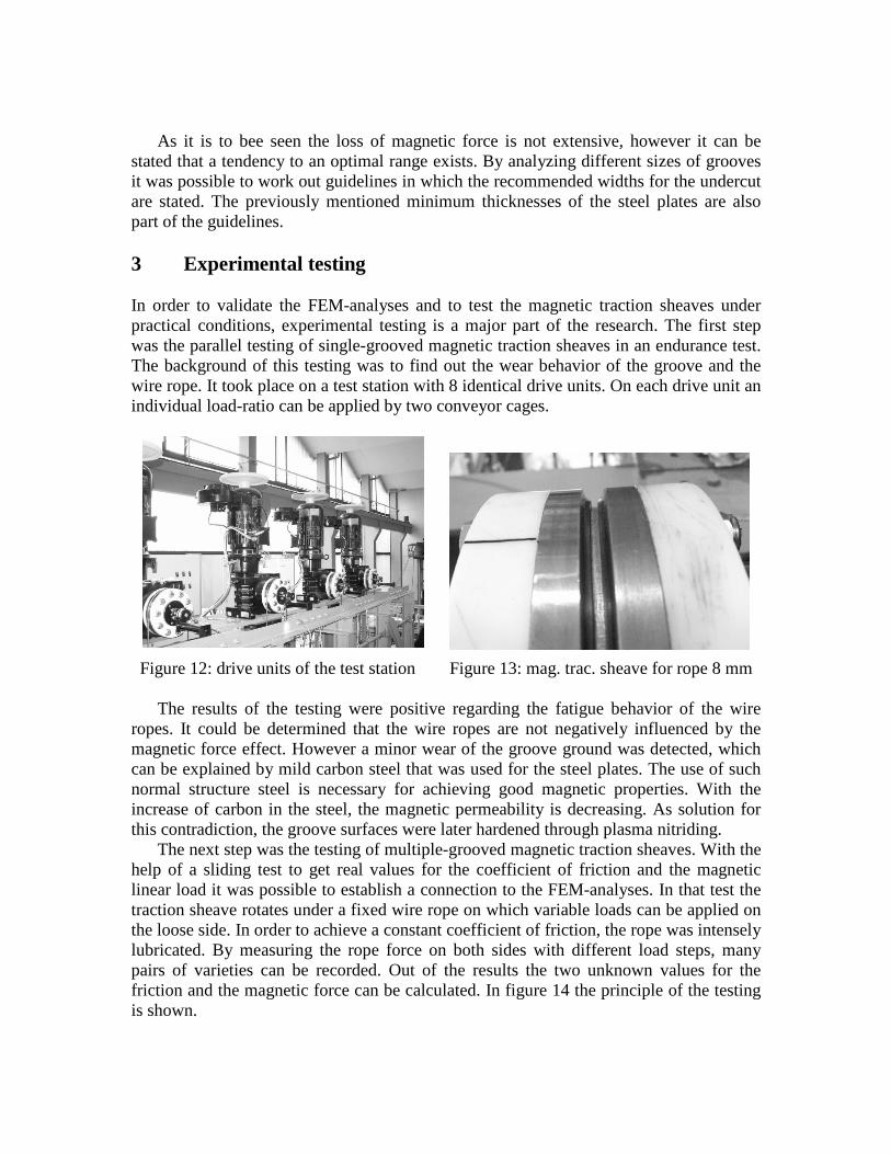
In order to validate the FEM-analyses and to test the magnetic traction sheaves under practical conditions, experimental testing is a major part of the research. The first step was the parallel testing of single-grooved magnetic traction sheaves in an endurance test. The background of this testing was to find out the wear behavior of the groove and the wire rope. It took place on a test station with 8 identical drive units. On each drive unit an individual load-ratio can be applied by two conveyor cages.
Figure 12: drive units of the test station Figure 13: mag. trac. sheave for rope 8 mm The results of the testing were positive regarding the fatigue behavior of the wire
ropes. It could be determined that the wire ropes are not negatively influenced by the magnetic force effect. However a minor wear of the groove ground was detected, which can be explained by mild carbon steel that was used for the steel plates. The use of such normal structure steel is necessary for achieving good magnetic properties. With the increase of carbon in the steel, the magnetic permeability is decreasing. As solution for this contradiction, the groove surfaces were later hardened through plasma nitriding.
The next step was the testing of multiple-grooved magnetic traction sheaves. With the help of a sliding test to get real values for the coefficient of friction and the magnetic linear load it was possible to establish a connection to the FEM-analyses. In that test the traction sheave rotates under a fixed wire rope on which variable loads can be applied on the loose side. In order to achieve a constant coefficient of friction, the rope was intensely lubricated. By measuring the rope force on both sides with different load steps, many pairs of varieties can be recorded. Out of the results the two unknown values for the friction and the magnetic force can be calculated. In figure 14 the principle of the testing is shown.
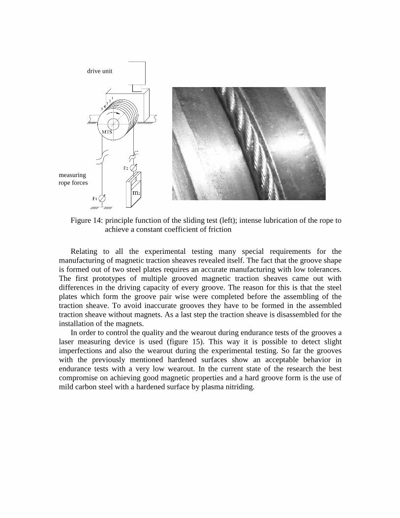
Figure 14: principle function of the sliding test (left); intense lubrication of the rope to achieve a constant coefficient of friction
Relating to all the experimental testing many special requirements for the
manufacturing of magnetic traction sheaves revealed itself. The fact that the groove shape is formed out of two steel plates requires an accurate manufacturing with low tolerances. The first prototypes of multiple grooved magnetic traction sheaves came out with differences in the driving capacity of every groove. The reason for this is that the steel plates which form the groove pair wise were completed before the assembling of the traction sheave. To avoid inaccurate grooves they have to be formed in the assembled traction sheave without magnets. As a last step the traction sheave is disassembled for the installation of the magnets.
In order to control the quality and the wearout during endurance tests of the grooves a laser measuring device is used (figure 15). This way it is possible to detect slight imperfections and also the wearout during the experimental testing. So far the grooves with the previously mentioned hardened surfaces show an acceptable behavior in endurance tests with a very low wearout. In the current state of the research the best compromise on achieving good magnetic properties and a hard groove form is the use of mild carbon steel with a hardened surface by plasma nitriding.
drive unit
measuring rope forces

-4
-3
-2
-1
0
1
2
3
-6 -5 -4 -3 -2 -1 1 2 3 4 5 6[mm]
[mm
]
default
measured
Figure 15: measuring the form of the grooves during the testing
4 Summary
The concept magnetic traction sheave is a proven possibility to increase the driving capacity in material handling systems. Depending on the point of view, different advantages can be derived. The general statement is the achievement of the same magnitude of driving capacity from a V-groove design with a round-groove design by using high performance permanent magnets. The comparison with a conventional round-groove design leads to a reduction of the masses of a system. If compared with a V-groove design directly, the service life of the wire rope can be increased significantly. The research on magnetic traction sheaves has shown the possible application of multiple-grooved magnetic traction sheaves with certain effects, which has to be taken under consideration.
The research will be proceeding in order to prove the positive effect on different applications with variable dimensions. Different hoisting and pulling devices like winches, service lifts, traction sheaves to relief stress on multilayer spooling rope drums and many more will be the concern of future research.
5 References
[1] Gräbner, P.: Treibscheibe für Hochleistungsreibpaarungen. Patent WO 03/076324 A 1, 7. März 2003.

[2] Gräbner, P.: Neue Wege bei der Anwendung des Leichtbaus in der Aufzugstechnik. In: Hebezeuge Fördermittel – Fachzeitschrift für Technische Logistik, Berlin 48 (2008) 5., S. 356-359 [3] Pajer, G.; Scheffler, M; Gräbner, P.; Adam, G.; Kurth, F.: Unstetigförderer 1.
Berlin: Verlag Technik, 1989: 5. stark bearbeitete Ausgabe. [4] TRA Technische Regeln für Aufzüge. Taschenbuch-Ausgabe 2001. Berlin-Wien-
Zürich: Carl Heymanns Verlag, Beuth-Verlag. [5] Usabiaga, H.; Madoz, M.A.; Ezkurra, M.; Pagalday, J.M.: Mechanical interaction
between wire ropes and sheaves. Proceedings of the OIPEEC Conference “Trends for Ropes: design, application, operation”: Athens, Greece (2006)
[6] Coey, J.M.D: Permanent magnet applications. Journal of Magnetism and
Magnetic Materials 248. ELSEVIER (2002), 441-456