multiple linker screening strategies for the development
TRANSCRIPT
Multiple Linker Screening Strategies for the Development of New Microporous
Coordination Polymers with Remarkable Surface Area
Jacob Van Oosterhout
Submitted as a requirement for graduation from the University of Michigan

i
Acknowledgments
First of all, I would like to thank Professor Adam Matzger for being an extremely
knowledgeable and helpful mentor, for having the trust in me to allow me a degree of autonomy,
and for fostering a unique and challenging research environment. I am also deeply indebted to
the University of Michigan and specifically UROP for providing me with the opportunity to
perform undergraduate research in a world-class environment. I would like to thank Jennifer
Schnobrich and Kyoungmoo Koh, with whom I closely collaborated with, for their careful
guidance and eagerness to provide pointers and to challenge my assumptions until every
statement could be backed up with robust data. The entire Matzger group deserves
acknowledgement for their friendliness and eagerness to help out an undergrad, and I would like
to especially thank Jeremy Feldblyum for his collaboration in exploring the properties of a
particularly tricky MCP, and Antek Wong-Foy for his assistance with the technical equipment
the research required.
I would be nothing (literally) without my family, and would like to thank my father Bob,
my mother Mary Ann, and my sister Maika for bearing my twenty-two years with grace and
poise. I would like to thank my father for teaching me how to ask questions, and for managing
my stress when experiments invariably performed poorly. Last, but certainly not least, I would
like to thank my great-uncle, Howard Burke, for fostering in me a love of chemistry and for
inspiring me to continue the "family tradition" of chemistry research. His experiences gave me a
direction to point towards during my tumultuous early undergraduate years. For that, and to
honor a long and productive career of organic research, I dedicate this thesis to Howard Burke.

ii
Table of Contents
Acknowledgments...........................................................................................................................................i
Chapter 1 - Introduction to Synthesis of Microporous Coordination Polymers ........................................... 1
Chapter 2 - Development of an MCP with remarkable surface area from mixture of two linear linkers ..... 7
Chapter 3 - Mixed linker studies of H2BDC, H2NDC, and H2BPDC and a highly porous MCP
isostructural to UMCM-8 ............................................................................................................................ 23

1
Chapter 1 - Introduction to Synthesis of Microporous Coordination Polymers 1.1 Introduction
Microporous coordinating polymers (MCPs) are composed of metal ions or metal clusters joined
by organic ligands, also called linkers, which can produce a rigid, microporous, crystalline
framework based on the flexibility of the organic linker. Research concerning MCPs has
exploded in the recent past due to enticing features such as ultra-high surface area1 and structural
stability, but also due to potential commercial applications in gas storage2, catalysis
3, and
separations of gases4 and liquids.
5 Variations in linker geometry and the chemical properties of
metals enable a sizable array of both established and potential avenues for MCP formation.
1.2 General Concepts
Reticular Synthesis
The vast array of avenues for MCP formation can render MCP discovery more of an art than a
science. Logical methods to predict how separate building units will combine to form an MCP
has been defined as reticular synthesis.6 Unlike synthetic methodologies prevalent in other
fields, such as retrosynthetic analysis in organic synthesis, the structural characteristics of metal
clusters and linking ligands are unchanged after reaction. As a result, reticular synthesis uses the
chemistry of metal clusters and linkers to predict MCP products. The zinc acetate cluster
[Zn4O(CO2)6], for instance, forms an octahedral building unit which, if the carboxylate C-atoms
are joined linearly such as with a benzene ring, can form a cubic MCP with high porosity, called
MOF-5.7 Changing the geometry of the organic linker to a triangular unit results in an MCP of a
completely different structure with large, well defined pores, known as MOF-177.8 Dicopper
complexes when bonded with carboxylates produce building units utilizing the well-known
copper paddlewheel geometric motif. Three carboxylates joined by a benzene ring in the form of

2
benzene-1,3,5-tricarboxylic acid form another stable MCP, HKUST-1.9 Combining the
chemistry of metal clusters with the geometry of linking ligands enables prediction and
discovery of a vast array of MCPs.
Surface Area and the BET Method
Adsorption refers to the process in which gas molecules come into contact with a solid and, due
to intermolecular forces, accumulate next to the adsorbant.10
The ability of MCPs to adsorb
gases is the most widely studies and potentially valuable aspect of MCP chemistry. Since MCPs
are composed of repeating units of porous frameworks, an MCP crystal has a vast quantity of
accessible pores, and accordingly, a large surface area for gas molecules to adsorb. Adsorption
information of MCPs is obtained by measuring gas uptake at a constant temperature. Two
primary models exist to correlate gas adsorption with accessible surface area. The Langmuir
model assumes that gases adsorb in monolayers directly to the walls of the adsorbant. An
alternative model proposed by Brunauer, Emmet and Teller, called the BET model, assumes
multiple layers are able to accumulate on the adsorbant, a process known as multilayer
adsorption.11
The possibility of multilayer adsorption results in the Langmuir model tending to
overestimate the accessible surface area of an MCP, rendering the BET model the preferred
predictive tool. Adsorption analysis in this thesis will use the BET model to predict surface
areas.
Interpenetration
Interpenetration is defined as the nonchemical conjoining of two separate frameworks in such a
fashion that separation of the frameworks would require the breaking of multiple bonds.12
Interpenetration greatly decreases the accessible pore size of a given MCP and consequently
reduces the accessible surface area. Two frameworks can either interpenetrate such that the

3
distance between the two lattices is maximized, which interpenetration specifically refers to, or
such that the distance between the two lattices are minimized, which is referred to as catenation.
Interpenetrated frameworks, despite significantly lower surface area, can still maintain
significant porosity13
sufficient to selectively adsorb gases. The studies contained in this thesis
primarily focus on maximizing accessible surface area of MCPs, so the differences between
interpenetrated and catenated structures are not relevant for the purposes of these studies.
Methodologies for MCP Characterization
X-ray diffraction is the most powerful tool available to chemists who wish to know the precise
structure of a crystalline solid. Two primary types of x-ray diffraction exist: single-crystal x-ray
diffraction and powder x-ray diffraction (PXRD). Single-crystal x-ray diffraction shines an
intense x-ray beam upon a crystal sample with minimal imperfections. X-rays are diffracted by
atoms in the crystal onto an x-ray detector. Analysis of the diffraction patterns can produce a
solved crystal structure. Single-crystal XRD is time consuming and requires very careful growth
of MCPs. PXRD, alternatively, uses powdered crystalline samples to yield a pattern which is
unique to the crystal's unit cell. PXRD cannot directly be used to solve the unit cell of a crystal,
but the unit cell can be modeled using various programs. Predicted powder patterns can easily
be obtained from these models and compared to experimental powder patterns.
1.3 Strategies Employed in MCP Discovery
Reticular synthesis remains a widely used strategy for MCP discovery. A specific offshoot of
reticular synthesis uses linkers which are similar to other linkers known to combine with metal
building units to yield MCPs, a process known as isoreticular anaylsis. Isoreticular synthesis
was coined by Yaghi, et al. in 2002 to yield the isoreticular metal-organic framework (IRMOF)
series of cubic MCPs.14
The IRMOF series of MCPs expanded on the MCP morphology known

4
to arise from a mixture of linear terephthalic acid linkers with Zn4O clusters to yield cubic MOF-
5. Variation of the geometry of linear linkers yielded cubic MCPs. Similar isoreticular studies
were also applied to triangular tritopic linkers of increasing size and copper salts to yield MCPs
of increasing porosity.15
Isoreticular studies come at a cost, since increasing linker size also
increases the likelihood of interpenetration while decreasing the structural stability of the MCP.
If an MCP encompases too much open space and thus lacks structural integrity, its structure may
collapse upon removal of solvent from crystal pores. Alternate methods for discovery of MCPs
involve examining unique linker geometries to formulate different building units for MCP
growth.
1.4 Research in the Matzger Group
The Matzger group has probed the cutting edge of MCP chemistry for the better part of a decade,
and has employed various methodologies for MCP discovery. Research in the Matzger group
demonstrated the ability to form MCPs from asymmetric linkers,16
developed a theoretical
platform for predicting an MCP's surface area based upon the ratio between the atomic mass of
the linker and metal,17
and pioneered polymer-induced heteronucleation as a method to
synthesize MCPs with different structures than MCPs that are obtained under more traditional
methods.18
UMCM-1 and UMCM-2, two MCPs displaying exceptionally high surface areas, were among
the first MCPs to show the value of mixed-linker systems in the synthesis of highly porous
MCPs.19,20
UMCM-1 combined a linear ditopic linker and a triangular tritopic linker with Zn4O
clusters to yield an MCP with very large pores. Lengthening the linear linker slightly yielded
UMCM-2, an MCP with a then-record BET surface area. UMCM-1 and UMCM-2 demonstrated
the ability to synthesize MCPs with surface areas in excess of the highest surface areas obtained

5
from MCPs composed of just one linker while also avoiding interpenetration and other structural
defects.
In addition, the Matzger group demonstrated a mixture of two linear linkers based on 4,4'-
biphenyldicarboxylic acid (H2BPDC) with constituent groups on the benzene rings form cubic
MCPs with greatly reduced interpenetration in comparison with MCPs formed from linear
unsubstituted linkers.21
Reaction of (H2BPDC) with Zn(NO3)2 yields a doubly interpenetrated
IRMOF-9 or, under extremely specific conditions not viable for industrial scale, non-
interpenetrated IRMOF-10.22
Interpenetrated IRMOF-9 has a BET surface area of 1700 m2/g,
while noninterpenetrated IRMOF-10 has a theoretical BET surface area of approx. 5000 m2/g.
23
Replacement of H2BPDC with 2,2',6,6'-tetramethylbiphenyl-4,4'-dicarboxylic acid
(H2Me4BPDC) added some steric bulk to the linker, but the steric hindrance provided by four
methyl groups was insufficient to prevent interpenetration. Replacement of H2BPDC with the
extremely bulky 9,10-bis(triisopropylsilyloxy)phenanthrene-2,7-dicarboxylate (TPDC, Figure
1.1) was sufficiently bulky to inhibit interpenetration but also blocked adsorption sites. A
mixture of H2Me4BPDC and TPDC with Zn(NO3)2 was found to yield a MCP with surface area
of up to 3000 m2/g. The results demonstrated that strategies exist to use a system of mixed
linkers of similar geometry to inhibit interpenetration while still yielding high surface areas.
Figure 1.1. H2Me4BPDC and H2TPDC.

6
1.5 Content of Thesis
The contents of the thesis described below examine the viability of using two linear linkers of
different lengths to afford highly porous MCPs while avoiding interpenetrated structures.
Research in the Matzger lab has demonstrated the viability of mixed linker systems in which the
linkers are of different geometry. Linkers of similar geometry but with different steric-hindering
groups can be combined to produce non-interpenetrated MCPs as well. This thesis displays the
viability of an alternate strategy for MCP design. Instead of adding different bulky groups to
yield a randomly mixed MCP, a mixture of two linear linkers of different length can yield highly
structured, highly stable MCPs with high surface area which are not prone to interpenetration.
Chapter two presents the synthesis of a UMCM-8, an MCP composed of two linear linkers
possessing remarkable surface area with no evidence of interpenetration. Chapter three presents
an isoreticular study based upon the results of the previous chapter, and shows the synthesis of
UMCM-9, an isostructural MCP to UMCM-8 with a BET surface area of almost 5000 m2/g. In
addition, a screen composed of three separate linear linkers of different lengths is shown and
analyzed. The results contained herein demonstrate the viability of systems of mixed linear
linkers to afford highly porous MCPs, which opens the sizable library of linear linkers to be
studied for viable 2-linker combinations.

7
Chapter 2 - Development of an MCP with remarkable surface area from mixture of two
linear linkers
2.1 Introduction
The discovery and synthesis of new MCPs with desirable properties tends to focus on the
reaction between an organic linking ligand and a metal cluster. Many researchers require a great
deal of trial and error to discover conditions which yield MCPs with large BET surface areas.
Reticular chemistry, or the examination of the geometry of the linker and metal ion used, can
predict the structure of an MCP. For example, Yaghi, et al, demonstrated with the IRMOF-X
series that linear linkers combine with octahedral Zn4O clusters to yield cubic MCPs with high
porosity. MOF-5, the simplest MCP of the IRMOF-X series, is composed of 1,4-
benzenedicarboxylic acid and Zn4O clusters. MOF-5 has a very good BET surface area of 3362
m2/g.
24 Current models predict an MCP isostructural to MOF-5 but with longer linkers to have a
greater BET surface area.17
However, IRMOF-8, a cubic MCP composed of Zn4O clusters and
2,6-napthalenedicarboxylic acid (H2NDC) can only reach a BET surface area of 1466 m2/g,
which is much lower than the maximum available BET surface area derived from the crystal
structure (4390 m2/g).
17 The severely reduced accessible surface area occurs due to
interpenetration of IRMOF-8 lattices. The overlapping crystal lattices impede gas adsorption
and reduce the effective surface area of an MCP.
2.2 Two-Linker Syntheses of Highly Porous MCPs
When multiple linkers are combined in the same pot in the presence of metal ions, one of two
reactions can occur. Each linker can react independently with the metal cluster different MCPs
composed of only one linker species, a process known as segregation. The linkers can also
combine together to produce a new material in a process known as copolymerization. Literature
data suggests that multiple linkers can induce copolymerization to yield MCPs with very high

8
surface areas. In our group, Kyoungmoo Koh presented the synthesis of UMCM-1 (University
of Michigan Crystalline Material), a highly porous MCP produced from H3BTB, 1,4-
benzinedicarboxilic acid (H2BDC) and zinc nitrate hexahydrate. UMCM-1 possesses a very high
BET surface area of 4160 m2/g. BDC and BTB copolymerized to form UMCM-1 only between
mole ratios of 3:2 and 1:1 BDC:BTB, and in other cases yielded a mixture of MOF-5, MOF-177,
and UMCM-1 (Figure 2.1).
Figure 2.1. Different phases resulting from reacting different mole ratios of BDC and NDC.19
2.3 Strategy
Octahedral Zn4O clusters and linear H2BDC and H2NDC linkers can be arranged to form a
specific number of tetragonal or cubic cages (Figure 2.2). We predicted
an MCP composed of both cubic and tetragonal cages would reduce interpenetration while
maintaining a robust, stable structure.

9
Figure 2.2. Possible cubic and tetragonal cage structures resulting from different arrangements of long and
short linear linkers with octahedral metal clusters.
A 2-linker screen composed of H2BDC and H2NDC would allow in depth study of the differing
structures which can result from a mixture of linear linkers. The screen would enable an

10
understanding of which long/short linker combinations would segregate and which combinations
would copolymerize into one of the cubic or tetragonal cage structures in Figure 2.2. In addition,
we would be able to discern whether or not one linker arrangement predominates over the others.
Mixed-linker solutions run the risk of having small quantities of segregated MCPs growing on a
copolymerized MCP, which would pose problems for single crystal x-ray diffraction. In order to
accurately determine the unit cell, a crystal sample must be pure and free of irregularities. Since
all possible structures which may result from the screen are known, the unit cells can be modeled
using Materials Studio. Predicted powder x-ray diffraction patterns can then be compared to
experimental powder x-ray diffraction patterns to determine crystal structure.
2.4 Analysis of BDC-NDC screen
A screen of base-ten mole ratios of H2BDC and H2NDC dissolved in diethylformamide (DEF)
with Zn4O clusters obtained isolated a pure MCP with a PXRD pattern different from existing
MCPs, 25
which we called UMCM-8 at a 1:1 mole ratio of BDC to NDC (Figure 2.3). Pure
MOF-5 was observed in all samples with a mole ratio of BDC:NDC of 7 or greater. A 6:4 mole
ratio of BDC:NDC yielded a mixture of UMCM-8 and MOF-5.

11
Figure 2.3. MCPs obtained from various mol ratios of H2BDC and H2NDC.
Samples containing between 60 and 80 mol % NDC were observed to have cubic UMCM-8
growing around impure phase crystals appeared similar to the highly phase-impure IRMOF-8
obtained in DEF. As a result, we hypothesize that IRMOF-8 forms more readily than UMCM-8
in samples of 40 mol % BDC or less and thus serves as a nucleation point for UMCM-8 growth.
MCPs have been demonstrated to be able to form core-shell MCPs, where previously formed
MCP grows a shell composed of a different MCP.26
Previous syntheses of core-shell MCPs
required seed MCPs to be obtained in one sample, which is then replaced with new mother liquor
containing the requisite linkers and metal clusters for formation of the shell MCP. A mixture of
H2BDC and H2NDC in mole ratios of 40% BDC or less appears to exhibit one-pot core-shell
MCP growth. However, the IRMOF-8 obtained from DEF is very phase-impure, and more
rigorous studies than visual observation to prove one-pot core-shell UMCM-8 and IRMOF-8
growth would be very difficult to perform.
1H-NMR analysis of the BDC-NDC screen shows the mol % BDC increasing in obtained
samples as the mol % BDC increased in solution preparation.27
Initial samples with 70 mol % or

12
greater BDC content yielded samples with zero observed NDC, representing pure MOF-5
(Figure 2.4). A 1:1 mol ratio of BDC:NDC produced UMCM-8 composed of 45% BDC.
Figure 2.4. Mol % BDC obtained by using various ratios of BDC and NDC in the presence of zinc nitrate.
The mol % in obtained samples closely matches a quadratic polynomial function when plotted
against mol % BDC in original solution. This correlation supports the hypothesis that quickly
forming IRMOF-8 serves as a nucleation point for UMCM-8. Formation of IRMOF-8 would
remove an excess of NDC from solution, which leaves less NDC to copolymerize with BDC to
form UMCM-8. MOF-5 appears not to engage in one-pot core-shell formation since unreacted
BDC is lost upon removal of mother liquor. Since 1:1 mol ratio of BDC:NDC yields a sample of
45 mol% BDC, we suspect slight quantities of IRMOF-8 exist in the center of UMCM-8 crystals.
The IRMOF-8 in the UMCM-8 crystals can disrupt attempts to solve the structure via single-
crystal x-ray diffraction while not having an overly adverse effect on surface area.
BDC quantities greater than 50 mol % showed that excess BDC overwhelmingly favored MOF-5
formation. Without a similar quantity of NDC, BDC will bind only to zinc clusters bound to
other BDC molecules to form MOF-5. Mechanistic studies, in which a mixture of BDC and
NDC is dissolved in deuterated n,n’-diethylformamide (DEF), and aliquots of mother liquor are
13
analyzed via NMR at specific intervals could give insights towards the rates of formation of
IRMOF-8 and UMCM-8, but such studies would have significant drawbacks and difficulties, not
the least of which is the fact that deuterated DEF is not commercially available.
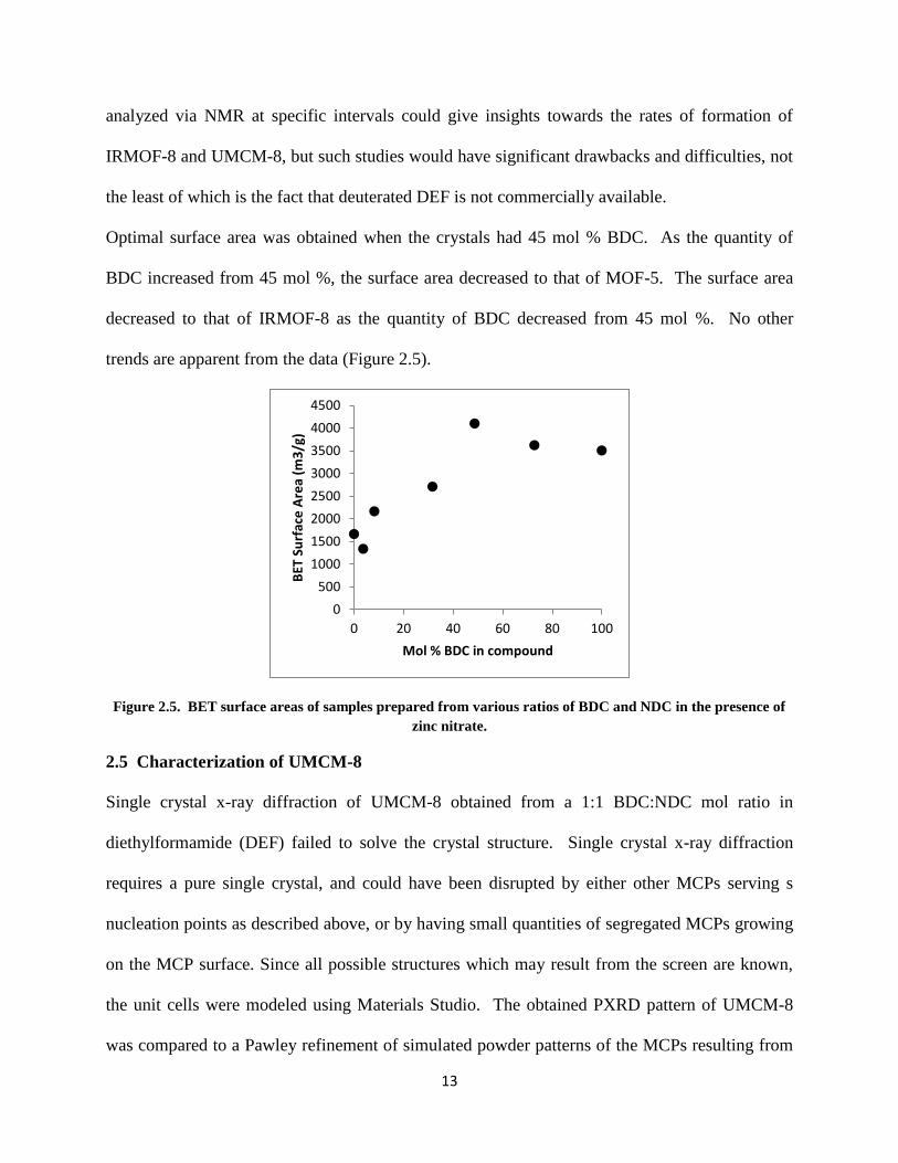
Optimal surface area was obtained when the crystals had 45 mol % BDC. As the quantity of
BDC increased from 45 mol %, the surface area decreased to that of MOF-5. The surface area
decreased to that of IRMOF-8 as the quantity of BDC decreased from 45 mol %. No other
trends are apparent from the data (Figure 2.5).
Figure 2.5. BET surface areas of samples prepared from various ratios of BDC and NDC in the presence of
zinc nitrate.
2.5 Characterization of UMCM-8
Single crystal x-ray diffraction of UMCM-8 obtained from a 1:1 BDC:NDC mol ratio in
diethylformamide (DEF) failed to solve the crystal structure. Single crystal x-ray diffraction
requires a pure single crystal, and could have been disrupted by either other MCPs serving s
nucleation points as described above, or by having small quantities of segregated MCPs growing
on the MCP surface. Since all possible structures which may result from the screen are known,
the unit cells were modeled using Materials Studio. The obtained PXRD pattern of UMCM-8
was compared to a Pawley refinement of simulated powder patterns of the MCPs resulting from
0
500
1000
1500
2000
2500
3000
3500
4000
4500
0 20 40 60 80 100
BET
Su
rfac
e A
rea
(m3
/g)
Mol % BDC in compound

14
various combinations of BDC and NDC. The experimental powder pattern matched the
simulated powder pattern of the MCP composed of 3 BDC and 3 NDC arranged facially (Figure
2.6).
2.6. Overlay of Pawley refinement results from PXRD patterns of simulated fac-(Zn4O)(BDC)3(NDC)3and
experimental PXRD patterns of UMCM-8.
Figure 2.7. a. UMCM-8 unit cell, composed of a cubic NDC and BDC cages connected by the corners. b.
Facially arranged Zn4O(BDC)3(NDC)3 UMCM-8 clusters.

15
The unit cell of UMCM-8 is a tetragonal unit cell composed of one cubic BDC cage, 8 cubic
NDC cages, 6 tetragonal cages composed of 8 BDC and 4 NDC, and 8 tetragonal cages
composed of 4 BDC and 8 NDC.
Figure 2.8. Tetragonal cages which compose UMCM-8. Short linkers represent BDC, long linkers represent
NDC.
The modeled structure of UMCM-8 predicted a BET surface area of 4005 m2/g, which is
significantly greater than that of both IRMOF-8 and MOF-5.28
Nitrogen adsorption analysis of
UMCM-8 gave a BET surface area of 4030 m2/g,
29 which translates well to the predicted surface
area. The close relationship between predicted and experimental surface areas suggests a lack of
structural defects, structural collapse, or interpenetration. BDC cages in UMCM-8's unit cell
prevent the BET surface area from exceeding the maximum surface area of non-interpenetrated
IRMOF-8. However, the additional complexity of the unit cell effectively inhibits
interpenetration of structures.
Thermal gravimetric analysis of UMCM-8 showed two primary weight-loss steps (Figure 2.9).
One weight-loss step between 25-100 °C was a 25% weight loss and corresponded to
evaporation of CH2Cl2 solvent. The second weight-loss step was between 425-525 °C and lost

16
32% weight, corresponding to structural collapse of UMCM-8. No weight loss steps between the
initial solvent evaporation and structural collapse were observed. The pores of UMCM-8 were
not too small to prevent the complete evaporation of dichloromethane solvent. The structural
collapse weight-loss step shows UMCM-8 to be stable to above 400 °C, displaying similar
stability properties to MOF-5.30
Figure 2.9. Thermal gravimetric analysis trace of UMCM-8 in minimal dichloromethane.
2.6 Conclusions
UMCM-8 proves that highly porous MCPs are obtainable from a mixture of linear ditopic
linkers. The mixed-linker strategy employed to synthesize UMCM-8 provides similar stability to
cubic MCPs such as MOF-5 while avoiding the interpenetration issues that plague IRMOF-8.
CH2Cl2 evaporation
Structural collapse

17
The mechanics of MCP formation in a mixed linker system are not fully understood, and may
warrant further study.
2.7 Experimental Section/Supporting Information
Synthesis of UMCM-8 H2BDC (0.460 g, 2.77 mmol) and H2NDC (0.598 g, 2.77 mmol) were
dissolved in 250 mL of DEF via sonication. Zn(NO3)2·6H2O (4.25 g, 14.28 mmol) was added to
the solution. The mixture was sonicated for 15 minutes then heated in an oven at 100° C for
three days. After three days, the sample was cooled to room temperature, and the crystals were
washed three times with DMF (250 mL). The crystals were then exchanged in dichloromethane
three times over the course of three days. Vacuum activation at room temperature removed the
solvent, yielding UMCM-8. The yield of the reaction, determined by the weight of dry UMCM-
8 (1.13 g), is 48.0% based on H2BDC.
Preparation of BDC-NDC screen Stock solutions of H2BDC (0.0264 g, 0.159 mmol in 6 mL
DEF), H2NDC (0.0343 g, 0.159 mmol in 6 mL DEF), and Zn(NO3)2·6H2O (0.2856 g, 0.960
mmol in 12 mL DEF) were prepared. The stock solutions were sonicated for 15 minutes. BDC
and NDC stock solutions were combined in 1 mL Zn stock solution in quantities equal to the
molar ratio of the linker (with sum of ten) multiplied by 100 L. The samples were heated in an
oven at 85° C, shaken after 15 minutes heat, then heated for 48 hours, when crystal formation
was observed. After crystal formation was observed, the samples were cooled to room
temperature, and the mother liquor was exchanged three times with DMF (2 mL). The samples
were then exchanged in dichloromethane three times over the course of three days. Crystalline
products remained in dichloromethane solvent.
Computer modeling Possible structures resulting from linear linkers were predicted by tiling
the repeating unit derived from the coordination modes. Geometric structures were optimized

18
using the Forcite Plus module in Material Studio 5.5 from Accelerys. BET surface areas were
predicted from the optimized geometric structures using PLATON v.14.31
X-ray diffraction Powder X-ray diffraction was performed on a Rigaku R-Axis Spider
diffractometer equipped with an image plate detector and Cu Kα radiation operating in
transmissionmode.Thesamplewassetat45°inχ,rotatedinφandoscillatedinωtominimize
preferred orientation.
Figure 2.10. Powder X-ray diffraction patterns of IRMOF-8 (top), UMCM-8 (middle), and MOF-5 (bottom).

19
Figure 2.11. Powder X-ray diffraction patterns of BDC-NDC screen, from pure NDC (top) to a 5:5
BDC:NDC mol ratio (bottom).
Figure 2.12. Powder X-ray diffraction patterns of BDC-NDC from 5:5 BDC:NDC mol ratio (top) to pure
BDC (bottom).

20
Gas Sorption Measurements N2 adsorption/desorption isotherms were measured
volumetrically at 77 K N2 adsorption/desorption isotherms were measured volumetrically at 77 K
in the range 1.00 × 10⁻⁵ ≤P/P0 ≤1.00withanAutosorb-1C outfitted with the micropore option
by Quantachrome Instruments (Boynton Beach, Florida USA), running version 1.2 of the ASWin
software package. Ultra-high purity He (99.999%, for void volume determination) and N2
(99.999%) were purchased from Cryogenic Gasses and used as received. Samples were stored in
CH2Cl2. UMCM-8 was dried under vacuum (< 0.1 millitorr) at room temperature. The resulting
mass of dried material in the cell was ~30 mg.
Figure 2.13. Nitrogen isotherm for UMCM-8 taken at 77 K.
0
200
400
600
800
1000
1200
1400
0 0.2 0.4 0.6 0.8 1
N2 u
pta
ke (
cm3/g
)
P/Po
ADS DES

21
Figure 2.14. BET fit for the N2 adsorption isotherm of UMCM-8 (BET SA = 4005 m2/g). The relative
pressurerange(0.02≤P/Po≤0.1)forcalculatingthesurfaceareasatisfiesthecriteriaforapplyingBET
theory.32
1H-NMR Studies of BDC-NDC screen Composition of linkers in MCPs was determined by
1H-NMR spectroscopy. Approx. 10 mg dried crystals were decomposed in 1 M NaOD in D2O
solution. NMR spectra were obtained on a Varian MR 400 400 MHz spectrometer.
y = 0.8685x + 0.001 R² = 0.9994
0
0.01
0.02
0.03
0.04
0.05
0.06
0.07
0.08
0.09
0.1
0 0.02 0.04 0.06 0.08 0.1 0.12
1/(
W((
Po
/P)-
1))
P/Po

22
Figure 2.15. 1H-NMR spectrum after digesting UMCM-8 in 1 M NaOD . Integration of the BDC and NDC
peaks yielded a BDC content of 45 mol %.
23
Chapter 3 - Mixed linker studies of H2BDC, H2NDC, and H2BPDC and a highly porous
MCP isostructural to UMCM-8
3.1 Introduction
Results of the previous chapter demonstrated the viability of combining H2BDC and H2NDC
with Zn4O clusters to synthesize a non-interpenetrated MCP with high surface area. Applying
the principles used in the synthesis of UMCM-8 to other mixed-linker systems can potentially
showcase the breadth of the synthetic strategy. Studies on based on UMCM-1 show longer
linkers can be used to produce an MCP similar to existing MCPs, but with much higher surface
area. Koh, et al. replaced H2BDC with thieno[3,2-b]thiophene-2,5-dicarboxylate (H2T2DC) to
produce UMCM-2, an MCP isostructural to UMCM-1 with over 5000 m2/g BET surface area.
20
Furukawa, et al. increased the length of both linkers, using 4,4',4''-[benzene-1,3,5-triyl-
tris(ethyne-2,1-diyl)]tribenzoate (H3BTE) and biphenyl-4,4'-dicarboxylate (H2BPDC) to produce
MOF-205, an MCP with BET surface area of 6240 m2/g.1 However, UMCM-1 and MOF-210
are not isostructrual. Scheme 1 shows the different linker combinations used to produce MCPs
with linkers similar to those used to produce UMCM-1.

24
Figure 3.1. Increasing the length of the linkers in a mixed linker system can greatly increase the surface area of
the resulting MCP.
On a similar note, replacing H2BDC or H2NDC with H2BPDC under the conditions used to
produce UMCM-8 may yield an MCP with greater surface area than UMCM-8 while
maintaining UMCM-8's resistance to structural interpenetration. BPDC is known to react with
Zn4O clusters to yield doubly interpenetrated IRMOF-9 and non-interpenetrated IRMOF-10, an
MCP isostructural to MOF-5 and IRMOF-8. IRMOF-9 possesses a BET surface area greater
than IRMOF-8 (1904 m2/g).
14
3.2 Strategy
A three-linker screen composed of H2BDC, H2NDC, and H2BPDC enables thorough exploration
of the bonding patterns of linear linkers. While the results at equivalent mol percent
concentrations of two linkers are known from UMCM-8 studies, and can thus be extrapolated
upon to predict the properties of BDC-BPDC and NDC-BPDC mixtures, the presence of three

25
linkers in one solution can add potentially unforeseen complexities to MCP formation. A large
screen enables the examination of a large number of differing linker-ratio concentrations. X-ray
diffraction, nitrogen adsorption, and 1H-NMR analyses of results will properly characterize any
newly discovered MCPs.
3.3 Analysis of three-linker screen composed of H2BDC, H2NDC, and H2BPDC
Due to solubility issues with H2BPDC, the screen was run in a 2:1 volumetric solution of n-
methylpyrrilidinone (NMP) to DEF. A mixture of three separate linkers could potentially yield
one single MCP composed of three different linkers, one single MCP composed of two linkers, a
mixture of MCPs composed of two linkers, or a mixture of MCPs composed of one linker.
Figure 3.2 shows, at points where the results could be identified, most mixtures of the three
linkers formed exactly one MCP. One new MCP powder pattern was consistently observed in
the screen, and was called UMCM-9.

26
Figure 3.2. Three-linker diagram of BDC-NDC-BPDC screen. From a given point, follow the line downard
to the left to obtain the BDC mol ratio, follow the line upward to the right to obtain the NDC mol ratio, and
follow the line across to the right to obtain the BPDC mol ratio. Shaded areas represent ratios where known
MCPs were obtained.
A mixture of MOF-5 and IRMOF-9 was observed at a 1:1 mol ratio of BDC and BPDC, as
opposed to a new MCP isostructural to UMCM-8. Two apparent crystal morphologies were
observed at equal concentrations of BDC and BPDC, but PXRD analysis showed one crystal
morphology to be composed of IRMOF-9, a doubly interpenetrated cubic MCP composed of
BPDC and Zn4O clusters, and the other to be composed of a mixture of IRMOF-9 and MOF-5
(Figure 3.3).

27
Figure 3.3. PXRD comparison between IRMOF-9 (top), MOF-5 (upper middle), and MCPs obtained from a
5:5 mol ratio of BDC and BPDC.
As Figure 3.3 demonstrates, the secondary morphology almost exactly matches the powder
pattern of IRMOF-9. The powder pattern of the primary morphology matches most peaks with
IRMOF 9, but also has peaks at 9.7°, 14.8°, 15.4° two-theta which closely match peaks observed
in MOF-5's powder pattern. Since no MCP similar to UMCM-8 was observed when H2BDC and
H2BPDC were mixed, it can be concluded that merely mixing linear linkers cannot guarantee the
formation of a single, highly porous MCP. Further study could determine the presence of an
upward limit to the difference in length between two linear linkers which can copolymerize to
form a 2-linker MCP.
The blank areas on Figure 3.2 represent BDC-NDC-BPDC ratios in which no specific MCP
could be identified. All blank ratios yielded one single MCP which displayed powder patterns
similar to those displayed by cubic MOF-5 and IRMOF-8, and tetragonal UMCM-8 and UMCM-
9. The locations of the peaks were shifted either to the right or to the left in comparison with
powder patterns of previously known MCPs. It is quite likely that these crystals possess unique
structures, but the high likelihood of linkers which do not directly contribute to the crystal

28
structure, as in the BDC-NDC screen, render single-crystal x-ray diffraction extremely difficult.
The addition of a third linker to a mixed-linker system greatly increases the number of potential
crystal structures, which rendered the modeling strategy used to address the BDC-NDC screen
unviable.
The asterisk in Figure 3.2 located at a 2:6:2 BDC-NDC-BPDC mol ratio corresponds to a sample
displaying intriguing characteristics. Powder x-ray diffraction of the sample matches very well
with the predicted powder pattern of non-interpenetrated IRMOF-8 (Figure 3.4-a). Instead of the
poor quality cube-like IRMOF-8 crystals (Figure 3.4-c), large, clear, cubic crystals (Figure 3.4-b)
are formed. In all other IRMOF-8 producing mol ratios, the IRMOF-8 was of poor phase purity,
similar to the IRMOF-8 obtained in the BDC-NDC screen in Chapter 2.
Figure 3.4. a. PXRD patterns of predicted non-interpenetrated IRMOF-8 (bottom) and sample obtained
from 2-6-2 mol ratio of BDC, NDC and BPDC (top). b. Cubic crystals obtained at 2-6-2 mol ratio of BDC,
NDC, and BPDC. c. Poor phase-purity IRMOF-8 obtained at other BDC-NDC-BPDC mol ratios.

29
A nitrogen adsorption isotherm of a 2:6:2 BDC-NDC-BPDC mol ratio gave a BET surface area
of 4263 m2/g, which closely matches the maximum available surface area of IRMOF-8.
17 It
would appear that a specific mol ratio of three linkers can yield non-interpenetrated IRMOF-8,
but single crystal x-ray diffraction failed to yield a solved crystal structure and 1H-NMR of
digested product in D2O showed significant presence of BDC and BPDC in the product.
Integration of key BDC and BPDC NMR peaks showed the IRMOF-8-like compound to be
composed of 13 mol % BDC, 80 mol % NDC, and 7 mol % BPDC. Since the IRMOF-8-like
compound is composed of 20% non-NDC linkers, we hypothesize that the sample is not pure
IRMOF-8 and could potentially contain small quantities of MOF-5 and IRMOF-9. In addition,
the inability of single-crystal diffraction to yield a crystal structure suggests that BDC and BPDC
are interacting in unknown ways within the crystal lattice. BDC and BPDC could potentially be
contributing to the crystal structure in a disorganized fashion, which is suggested by a lack of
PXRD peaks which do not match with the predicted PXRD pattern of non-interpenetrated
IRMOF-8. However, why the specific 2-6-2 mol ratio of BDC, NDC, and BPDC forms the
highly porous IRMOF-8-like substance and not similar mol ratios of linkers is unknown and
difficult to determine experimentally.
3.4 Discovery of UMCM-9, an MCP isostructural to UMCM-8 displaying remarkable
surface area
UMCM-9 was found to have a tetragonal unit cell isostructural to UMCM-8 (Figure 3.5-a)
resulting from NDC and BPDC ligands coordinated to Zn4O clusters in a facial arrangement
(Figure 3.5-b).

30
Figure 3.5. a. Unit cell structure of UMCM-9, composed of cubic NDC and BPDC cages connected at the
corner. b. Facially arranged Zn4O(NDC)3(BPDC)3 UMCM-9 cluster.
Like UMCM-8, UMCM-9's unit cell is composed of one cubic BPDC cage, 8 cubic NDC cages,
6 tetragonal cages composed of 8 BPDC and 4 NDC, and 8 tetragonal cages composed of 4
BPDC and 8 NDC.
As attempts to use single-crystal x-ray diffraction to solve the crystal structure of UMCM-9
failed due to consistently poor diffraction of the crystals, the UMCM-9 unit cell was modeled.
Pawley refinements of the modeled structure were compared to PXRD patterns obtained from
UMCM-9 samples. A Pawley refinement of the powder x-ray pattern of the modeled structure
closely matches the experimental results obtained from a 1:1 mol ratio of H2NDC and H2BPDC
(Figure 3.6).
a
b

31
Figure 3.6. Overlay of Pawley refinement results from PXRD patterns of simulated fac-
(Zn4O)(NDC)3(BPDC)3and experimental PXRD patterns of UMCM-9.
Analysis of the simulated UMCM-9 structure using PLATON predicted a BET surface area of
4900 m2/g. However, a nitrogen adsorption isotherm taken after traditional evacuation of
dichloromethane solvent under vacuum yielded a BET surface area of only 1330 m2/g. PXRD
patterns of UMCM-9 before and after dichloromethane evacuation (Figure 3.7) suggest a
structural change in the crystal after evacuation, which is indicative of structural collapse.

32
Figure 3.7. PXRD pattern of UMCM-9 before evacuation of dichloromethane solvent (bottom) and UMCM-9
after evacuation of dichloromethane solvent (top).
Although the peaks at 5.5° and 11° two-theta are unchanged after evacuation, the smaller peak at
7.8° two-theta shifts significantly, suggesting significant structural changes in the tetragonal
cage.
Alternate methods of solvent removal exist which can reduce the likelihood of structural collapse
during activation of MCPs. Instead of the traditional activation method, in which the mother
liquor (usually DMF or DEF) is exchanged with a more volatile solvent such as dichloromethane
or THF, which is then evacuated under vacuum, Nelson, et. al. proposed activation via
supercritical CO2 as a method to greatly increase accessible surface area.33
It was hypothesized
that, since CO2 at temperatures and pressures above the critical point lacks surface tension,
capillary forces would prevent the structural collapse of the MCP.
A nitrogen adsorption isotherm of UMCM-9 after supercritical CO2 activation showed activated
UMCM-9 to have a BET surface area of 4969 m2/g. Had UMCM-9 suffered from
interpenetration and not structural collapse, CO2 activation of UMCM-9 should not have yielded
such a dramatic increase in accessible surface area.

33
Thermal gravimetric analysis of UMCM-9 showed two primary weight-loss steps – solvent
evaporation finishing at approximately 50° C, and structural collapse between 400-500° C
(Figure 3.8). Structural collapse represented a 42% weight loss. Like UMCM-8, no weight loss
steps were observed between solvent evaporation and structural collapse. If UMCM-8’spores
were too large to prevent complete evaporation of dichloromethane solvent, UMCM-9’s larger
framework would be expected to yield similar results. UMCM-9 has slightly lower thermal
stability than UMCM-8, but is still stable up to 400°C. Thermal stability of UMCM-9 similar to
MOF-5,30
along with the BET surface area obtained after supercritical CO2 activation,
demonstrates that UMCM-9 possesses the structural integrity afforded by cubic MCPs while
avoiding interpenetration issues which plague IRMOF-8 and IRMOF-9.
Figure 3.8. TGA trace of UMCM-9 in minimal dichloromethane.

34
3.5 Conclusions
A screen composed of three linear linkers H2BDC, H2NDC, and H2BPDC demonstrated the
strengths and limitations of multiple linker screens. Equal mol ratios of H2NDC and H2BPDC
were combined to yield highly porous, noninterpenetrated UMCM-9. Structural stability
concerns mandate CO2 activation to achieve high surface areas for UMCM-9. Some
combinations of linear linkers, such as a combination of H2BDC and H2BPDC, fail to
copolymerize into a new MCP. A three-linker screen can showcase peculiar and unexplained
chemistry as demonstrated by the formation of a structure very similar to IRMOF-8 at one
specific combination of linkers and displaying remarkable porosity, but containing significant
quantities of BDC and BPDC.
3.6 Experimental Section/Supporting Information
Synthesis of UMCM-9 H2NDC (28.7 mg, 0.132 mmol) and H2BPDC (35.6 mg, 0.147 mmol)
were dissolved in a mixture of 6.7 mL of DEF and 13.3 mL of N-methyl pyrrolidone.
Zn(NO3)2·6H2O (0.238 g, 0.800 mmol) was added to the solution. The mixture was sonicated
for 15 min and heated to 85 °C. After 4 days, crystals of a single phase were obtained. After
cooling to room temperature the product was isolated by decanting the mother liquor and
washing with DMF (3 × 20 mL). The resulting solid was then immersed in 20 mL CH2Cl2 for 2
days, during which time the CH2Cl2 was replaced three times then sample was stored in CH2Cl2.
The yield of the reaction, determined from the weight of the solvent-free material (57.9 mg), is
41.8 % based on H2NDC.
Supercritical CO2 Activation of UMCM-9 Activation was performed with a Jasco PU-1580-
CO2 delivery pump equipped with a back pressure regulator (Jasco BP-1580-81). The CH2Cl2-

35
soaked sample (0.1 g) was placed a metal column and CH2Cl2 was exchanged with liquid CO2 at
100 bar; the liquid CO2–charged column was heated at 35 °C for 30 min. CO2 was vented over
30 minutes via the back pressure regulator to obtain the activated sample.
Preparation of Three-Linker Screen
Stock solutions of H2BDC (0.1055 g, 0.635 mmol in a mixture of 16 mL NMP and 8 mL DEF),
H2NDC (0.1372 g, 0.635 mmol in a mixture of 16 mL NMP and 8 mL DEF), H2BPDC (0.1715
g, 0.635 mmol in a mixture of 16 mL NMP and 8 mL DEF), and Zn(NO3)2·6H2O (1.714 g, 5.76
mmol in a mixture of 48 mL NMP and 24 mL DEF) were prepared and sonicated for 15 minutes.
The screen was prepared by adding to one mL Zn stock solution each ratio of BDC, NDC, and
BPDC adding up to 1 mL. For example, the 3:3:4 BDC:NDC:BPDC sample was prepared by
adding 300 L BDC stock solution, 300 L NDC stock solution, and 400 L BPDC stock
solution to 1 mL Zn stock solution. All samples were heated to 85 °C, shaken after 15 minutes
heat, then left in the oven. After 4 days, crystal formation was observed. All samples were
cooled to room temperature, and products were isolated by decanting the mother liquor and
washing with DMF (3 × 2 mL per sample). The resulting solids were each immersed in 2 mL
CH2Cl2 for three days, during which time the CH2Cl2 was replaced with fresh CH2Cl2 three
times.
Preparation of IRMOF-8-like sample
H2BDC (0.0088 g, 0.0529 mmol), H2NDC (0.0343 g, 0.1587 mmol), and H2BPDC (0.0357 g,
0.0529 mmol) were dissolved in a mixture of 12 mL NMP and 8 mL DEF. Zn(NO3)2·6H2O
(0.2380 g, 0.800 mmol) was added to the solution, which was then sonicated for 15 minutes, then
heated to 85 °C. The sample was shaken after 15 minutes heating, then left in the oven. After 4
days, crystals of a single phase were obtained. After cooling to room temperature the product

36
was isolated by decanting the mother liquor and washing with DMF (3 × 20 mL). The resulting
solid was then immersed in 20 mL CH2Cl2 for 2 days, during which time the CH2Cl2 was
replaced three times then sample was stored in CH2Cl2.
X-ray diffraction Powder X-ray diffraction was performed on a Rigaku R-Axis Spider
diffractometer equipped with an image plate detector and Cu Kα radiation operating in
transmissionmode.Thesamplewassetat45°inχ,rotated inφandoscillatedinωtominimize
preferred orientation.

37
Figure 3.9. PXRD patterns of IRMOF-9, UMCM-9, IRMOF-8, UMCM-8, and MOF-5 (top to bottom).
Gas Sorption Measurements N2 adsorption/desorption isotherms were measured
volumetrically at 77 K N2 adsorption/desorption isotherms were measured volumetrically at 77 K
in the range 1.00 × 10⁻⁵ ≤P/P0 ≤1.00withanAutosorb-1C outfitted with the micropore option
by Quantachrome Instruments (Boynton Beach, Florida USA), running version 1.2 of the ASWin
software package. Ultra-high purity He (99.999%, for void volume determination) and N2
(99.999%) were purchased from Cryogenic Gasses and used as received. Samples were stored in

38
CH2Cl2. Samples were dried under vacuum (< 0.1 millitorr) at room temperature. The resulting
mass of dried material in the cell was ~30 mg.
Figure 3.10. Nitrogen adsorption isotherms taken at 77 K for UMCM 9 after conventional solvent evacuation
(black) and supercritical CO2 activation (gray).
Figure 3.11. BET fit for the N2 adsorption isotherm of UMCM-9 (BET SA = 4969 m2/g). The relative
pressurerange(0.05≤P/Po≤0.1)for calculating the surface area satisfies the criteria for applying BET
theory.23
0
200
400
600
800
1000
1200
1400
1600
0 0.2 0.4 0.6 0.8 1
N2 u
pta
ke (
cm3/g
)
P/Po
ADS (supercritical CO2) DES (supercritical CO2)
ADS (conventional) DES (conventional)
y = 0.6996x + 0.0017 R² = 0.9993
0
0.01
0.02
0.03
0.04
0.05
0.06
0.07
0.08
0 0.02 0.04 0.06 0.08 0.1 0.12
1/(
W((
Po
/P)-
1))
P/Po

39
Figure 3.12. Nitrogen adsorption isotherm taken at 77 K of sample obtained from a 2:6:2 BDC-NDC-BPDC
mol ratio.
Figure 3.13. BET fit for the N2 adsorption isotherm of sample obtained from a 2:6:2 BDC-NDC-BPDC mol
ratio (BET SA = 4263 m2/g).Therelativepressurerange(0.05≤P/Po≤0.1)forcalculatingthesurfacearea
satisfies the criteria for applying BET theory.23
0
200
400
600
800
1000
1200
1400
0 0.2 0.4 0.6 0.8 1
N2
Up
take
(cm
3 /g)
P/P0
Adsorption Desorption
y = 0.8165x + 0.0004 R² = 0.9991
0.00E+00
1.00E-02
2.00E-02
3.00E-02
4.00E-02
5.00E-02
6.00E-02
7.00E-02
8.00E-02
9.00E-02
0 0.02 0.04 0.06 0.08 0.1 0.12
1 /
(W((
P0/
P)
- 1
))
P/P0

40
1H-NMR Studies of UMCM-9 and BDC-NDC-BPDC screen Composition of linkers in MCPs
was determined by 1H-NMR spectroscopy. Approx. 10 mg dried crystals were decomposed in 1
M NaOD in D2O solution. NMR spectra were obtained on a Varian MR 400 400 MHz
spectrometer.
Figure 3.14. 1H-NMR spectrum of UMCM-9 after digesting in 4 wt% NaOD solution. From the integration
values of peaks, the empirical formula is estimated as Zn4O(NDC)1.32(BPDC)1.68.
Figure 3.15. 1H-NMR spectrum of sample obtained from a 2-6-2 BDC-NDC-BPDC mol ratio after digesting
in 4 wt% NaOD solution. From the integration values of the peaks, the sample contains 13 mol % BDC, 80
mol % NDC, and 7 mol % BPDC.

41
References
1 Furukawa, H.; Ko, N.; Go, Y. B.; Aratani, N.; Choi, S. B.; Choi, E.; Yazaydin, A. O.; Snurr, R. Q.; O'Keeffe, M.; Kim, J.;
Yaghi, O. M. Science 2010, 329, 424-428
2 Murray, L. J.; Dinca, M.; Long, J. R. Chem. Soc. Rev. 2009, 38, 1294-1314.
3 Lee, J.; Farha, O. K.; Roberts, J.; Scheidt, K. A.; Nguyen, S. T.; Hupp, J. T., Chem Soc Rev 2009, 38 (5), 1450-1459.
4 Keskin, S.; van Heest, T. M.; Sholl, D. S., Chemsuschem 2010, 3 (8), 879-891.
5 Cychosz, K. A.; Wong-Foy, A. G.; Matzger, A. J., J Am Chem Soc 2009, 131 (40), 14538-14543..
6 Yaghi, O. M.; O'Keeffe, M.; Ockwig, N. W.; Chae, H. K.; Eddaoudi, M.; Kim, J., Nature 2003, 423 (6941), 705-714.
7 Rosi, N. L.; Eckert, J.; Eddaoudi, M.; Vodak, D. T.; Kim, J.; O'Keeffe, M.; Yaghi, O. M., Science 2003, 300 (5622),
1127-1129.
8 Chae, H. K.; Siberio-Perez, D. Y.; Kim, J.; Go, Y.; Eddaoudi, M.; Matzger, A. J.; O'Keeffe, M.; Yaghi, O. M., Nature
2004, 427 (6974), 523-527.
9 Chui, S. S. Y.; Lo, S. M. F.; Charmant, J. P. H.; Orpen, A. G.; Williams, I. D., Science 1999, 283 (5405), 1148-1150.
10 Sing, K. S. W.; Everett, D. H.; Haul, R. A. W.; Moscou, L.; Pierotti, R. A.; Rouquerol, J.; Siemieniewska, T., Pure and
Applied Chemistry 1985, 57 (4), 603-619.
11 S. Brunauer, P. H. Emmett and E. Teller, J. Am. Chem. Soc., 1938, 60, 309.
12 Batten, S. R.; Robson, R., Angew Chem Int Edit 1998, 37 (11), 1460-1494.
13 Reineke, T. M.; Eddaoudi, M.; Moler, D.; O'Keeffe, M.; Yaghi, O. M., J Am Chem Soc 2000, 122 (19), 4843-4844.
14 Eddaoudi, M.; Kim, J.; Rosi, N.; Vodak, D.; Wachter, J.; O'Keeffe, M.; Yaghi, O. M., Science 2002, 295 (5554), 469-
472.
15 Yuan, D. Q.; Zhao, D.; Sun, D. F.; Zhou, H. C., Angew Chem Int Edit 2010, 49 (31), 5357-5361.
16 Wong-Foy, A. G.; Lebel, O.; Matzger, A. J., J Am Chem Soc 2007, 129 (51), 15740-15741.
17 Schnobrich, J. K.; Koh, K.; Sura, K. N.; Matzger, A. J. Langmuir 2010, 26, 5808.
18 Grzesiak, A. L.; Uribe, F. J.; Ockwig, N. W.; Yaghi, O. M.; Matzger, A. J., Angew Chem Int Edit 2006, 45 (16), 2553-
2556.
19Koh, K.; Wong-Foy, A. G.; Matzger, A. J., Angew Chem Int Edit 2008, 47 (4), 677-680.
20 Koh, K.; Wong-Foy, A. G.; Matzger, A. J., J Am Chem Soc 2009, 131 (12), 4184-4185.
21 Park, T. H.; Koh, K.; Wong-Foy, A. G.; Matzger, A. J., Crystal Growth & Design 2011, 11 (6), 2059-2063.

42
22
Rowsell, J. L. C.; Yaghi, O. M., J Am Chem Soc 2006, 128 (4), 1304-1315.
23 Walton, K. S.; Snurr, R. Q., J Am Chem Soc 2007, 129 (27), 8552-8556.
24 Rowsell, J. L. C.; Millward, A. R.; Park, K. S.; Yaghi, O. M. 2004, 126, 5666-5667.
25 See supporting Information for powder patterns.
26 Koh, K.; Wong-Foy, A. G.; Matzger, A. J., Chem Commun 2009, (41), 6162-6164.
27 For detailed explanation of NMR methodology, see Supporting Information
28 For an explanation of computational methods, see Supporting Information
29 For an explanation of surface area studies, see Supporting Information.
30 Liu, Y. Y.; Ng, Z. F.; Khan, E. A.; Jeong, H. K.; Ching, C. B.; Lai, Z. P., Microporous and Mesoporous Materials 2009,
118 (1-3), 296-301.
31 Spek, A. L. J Appl. Cryst. 2003, 36, 7-13.
32 Walton, K. S.; Snurr, R. Q. 2007, 129, 8552-8556.
33 Nelson, A. P.; Farha, O. K.; Mulfort, K. L.; Hupp, J. T., J Am Chem Soc 2009, 131 (2), 458-460.