multiple-patterning optimizations for the long run · • full-chip coloring vs....
TRANSCRIPT

A. B. Kahng, ICCAD-2011 Litho Workshop, 111110
Multiple-Patterning Optimizations for the Long Run
Andrew B. KahngUCSD VLSI CAD Laboratory
http://vlsicad.ucsd.edu/

(2)A. B. Kahng, ICCAD-2011 Litho Workshop, 111110
Multiple-Patterning Lithography (MPL)• MPL is needed in sub-30nm foundry nodes
• Limitations of 193i• Timing of EUV• So far, DPL and TPL; QPL on the way
• MPL is now a likely multi-node solution for both FEOL and BEOL patterning
• MPL may also be used in future EUV contexts• E.g., 13.6nm EUV + SADP for 11nm HP
• Multiple patterning steps give rise to a number of graph coloring-centric optimizations • E.g., pattern splitting, mask coloring assignment

(3)A. B. Kahng, ICCAD-2011 Litho Workshop, 111110
Many Design Technology and Flow Issues• Lack of clear MPL design guidelines
• Designer-foundry iterations increase design TAT• Hard to co-optimize between foundry and designers
• Understanding tradeoffs between MPL approaches• Design restrictions vs. DRC checks, density, variability, …
• Library design and characterization• Full-chip coloring vs. correct-by-composition coloring• Timing models for multiple stitching/coloring solutions
• MPL-aware placement and routing• How much mask design is done and fixed in P&R tool?• Gridless or gridded routing?• Is routability estimation now broken?

(4)A. B. Kahng, ICCAD-2011 Litho Workshop, 111110
Agenda• LELE• SADP• Futures
• Will try to touch on:• Where academic research is today (UCLA, UT, UIUC)• Some of the elephants in the room

(5)A. B. Kahng, ICCAD-2011 Litho Workshop, 111110
Variability in LELE Lithography
1 2 1 2 1
W W
S S
mask2
Positive photoresistDielectric
Positive-Tone LELE (in BEOL) Linewidth variation
Negative-Tone LELE (in BEOL) Space variation
mask1
After exposure + etchCu filling
(misaligned to left)

(6)A. B. Kahng, ICCAD-2011 Litho Workshop, 111110
• Comparison of design guardband (Min-Max delay)• Unimodal representation is too pessimistic
Impact of Bimodality on Guardband
CD mean difference
Large CD group
Small CD group
0.0E+00
5.0E-12
1.0E-11
1.5E-11
2.0E-11
2.5E-11
3.0E-11
1 nm 2 nm 3 nm 4 nm 5 nm 6 nm
Del
ay (s
)
CD Mean Difference
Best case: Large CD groupWorst case: Large CD groupBest case: Small CD groupWorst case: Small CD groupBest case: Pooled CDWorst case: Pooled CD
Green linesfrom 1st patterning
Blue linesfrom 2nd
patterning

(7)A. B. Kahng, ICCAD-2011 Litho Workshop, 111110
Impact of Bimodality on Path Delay• Bimodality can help reduce path delay variation
• Reduction of covariance when alternately colored
C12 C12 C12 C12
C12 C21 C12 C21
++
++
+-
+-
+4
0
Variation () is accumulated
Variation () is compensated
0
5
10
15
20
25
0 1 2 3 4 5 6CD Mean Difference (nm)
Uniform
Alternate
Sigm
a / M
ean
(%)
SPICE Simulation Results
(8)A. B. Kahng, ICCAD-2011 Litho Workshop, 111110
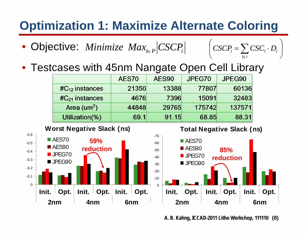
Optimization 1: Maximize Alternate Coloring• Objective:
• Testcases with 45nm Nangate Open Cell Library
iPi CSCPMaxMinimize
-0.6
-0.5
-0.4
-0.3
-0.2
-0.1
0
Init. Alt. Init. Alt. Init. Alt.
2nm 4nm 6nm
Worst Negative Slack (ns)
AES70AES90JPEG70JPEG90
-70
-60
-50
-40
-30
-20
-10
0
Init. Alt. Init. Alt. Init. Alt.
2nm 4nm 6nm
Total Negative Slack (ns)
AES70AES90JPEG70JPEG90
Init. Opt.2nm
Init. Opt.4nm
Init. Opt.6nm
Init. Opt.2nm
Init. Opt.4nm
Init. Opt.6nm
59% reduction 85%
reduction
ilili DCSCCSCP
(9)A. B. Kahng, ICCAD-2011 Litho Workshop, 111110
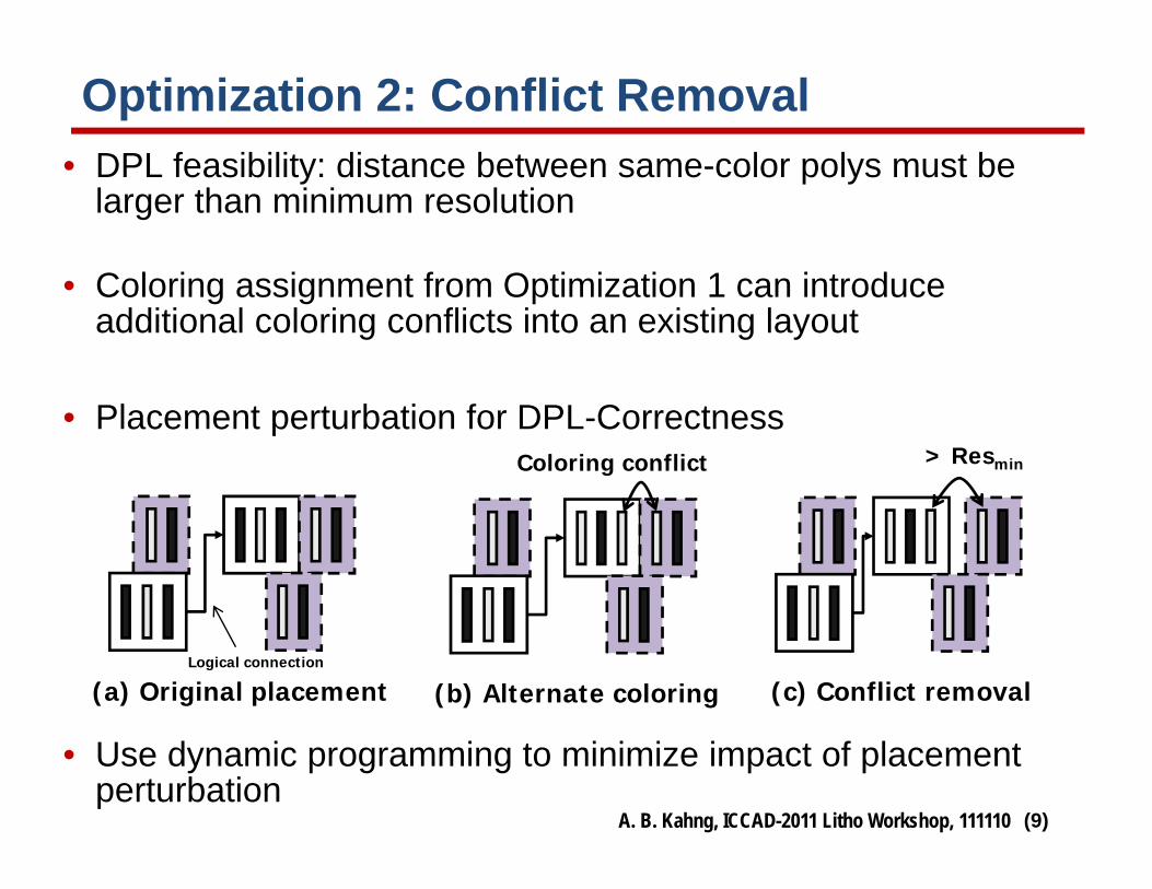
Optimization 2: Conflict Removal• DPL feasibility: distance between same-color polys must be
larger than minimum resolution
• Coloring assignment from Optimization 1 can introduce additional coloring conflicts into an existing layout
• Placement perturbation for DPL-Correctness
• Use dynamic programming to minimize impact of placement perturbation
(a) Original placementLogical connection
(b) Alternate coloring
Coloring conflict
(c) Conflict removal
> Resmin

(10)A. B. Kahng, ICCAD-2011 Litho Workshop, 111110
Overall Mitigation of DPL Bimodality
• Bimodal timing model Reduce pessimism• Alternate coloring Improve timing• Placement perturbation Remove conflicts
Stage #Conflict TimingMetric
Mean CD Difference2nm 4nm 6nm
Initial Coloring(Unimodal) 0
WNS (ns) -1.113 -2.016 -2.902TNS (ns) -671.1 -1776.3 -3348.5
Initial Coloring(Bimodal) 0
WNS (ns) -0.191 -0.354 -0.527TNS (ns) -8.17 -26.56 -64.64
AlternateColoring 219
WNS (ns) -0.090 -0.145 -0.267TNS (ns) -1.48 -3.85 -22.40
DPL-Corr(+ECO Routing) 0
WNS (ns) -0.104 -0.183 -0.295TNS (ns) -3.43 -10.45 -28.42
Library/IP + .lib model + SP&R + signoff + PV + MDP = (Bad AND Ugly)!

(11)A. B. Kahng, ICCAD-2011 Litho Workshop, 111110
• Three interconnect patterns
• Study impact of stitching strategy on RC and circuit delay
• Derive analytical RC equations for LELE DPL with overlay and bimodal CD distribution
Ground plane
Ground cap.Coupling cap.
neighborsvictim
Color 1
Color 2
Which stitching location is better?
Experiment setup:
Single patterning (SPL) DPL symmetric DPL asymmetricGround plane
Ground cap.Coupling cap.
neighborsvictim
Ground plane
Ground cap.Coupling cap.
neighborsvictim
Guidelines for BEOL with LELE DPL
T. B. Chan, UCSD, BACUS 2011

(12)A. B. Kahng, ICCAD-2011 Litho Workshop, 111110
Stitching Impact on Delay
• Optimal stitching location shifts to the driver side due to resistance shielding effect
• Similar trends are observed for 45nm and 22nm
10.00%
15.00%
20.00%
25.00%
1 3 5 7 9 11 13 15 17 19 213
/Mean de
lay (%
)
stitching location
10.00%
15.00%
20.00%
25.00%
1 3 5 7 9 11 13 15 17 19 21
3/M
ean de
lay (%
)
stitching location
45nm technology 22nm technology
driver receiver
Color 1 Color 2Color 1 Color 2
20 RC modules
delay
stitching location
T. B. Chan, BACUS 2011

(13)A. B. Kahng, ICCAD-2011 Litho Workshop, 111110
UCLA Framework for DP-Enabled Design
• O(n) coloring followed by LP-based conflict removal • Simultaneously fixes all conflicts without creating others• No need for iterative loop of coloring + legalization• Handling of spacing rules is done cleanly
Design with Conventional
Rules
Layout Simplification
Mask Assignment
Sign-offYes
LP for Conflict Removal w/ Fixed Area
LP for Conflict Removal
w/ Area Increase
DP Layers & Constraint Definition
Optional
Conflict = 0 ?
No
Optional
R. Ghaida, UCLA, ICCAD 2011

(14)A. B. Kahng, ICCAD-2011 Litho Workshop, 111110
Layout Decomposition
• Design rule-dependent projection• Project from each lineside and lineend based on rule value• Color violating parts and insert stitches
• Use all candidate stitches Guarantee to find a coloring solution if one exists
• No segmentation • Handles tip-to-tip, tip-to-side, side-to-side, and min size rules naturally• Dealing with polygons rather than rectangles smaller problem size
Violating partsNon‐violating parts
R. Ghaida, UCLA, ICCAD 2011

(15)A. B. Kahng, ICCAD-2011 Litho Workshop, 111110
Minimize layout perturbation
DP rules
Xi = current location, Xinit = initial location of edge iWi = weight, Aij = arc b/w edges i and j, dij = DR value
LP-based Legalization with Min Perturbation
ijijij
i
initiii
AdXXts
XXWMin
,:..
||
R. Ghaida, UCLA, ICCAD 2011
(16)A. B. Kahng, ICCAD-2011 Litho Workshop, 111110
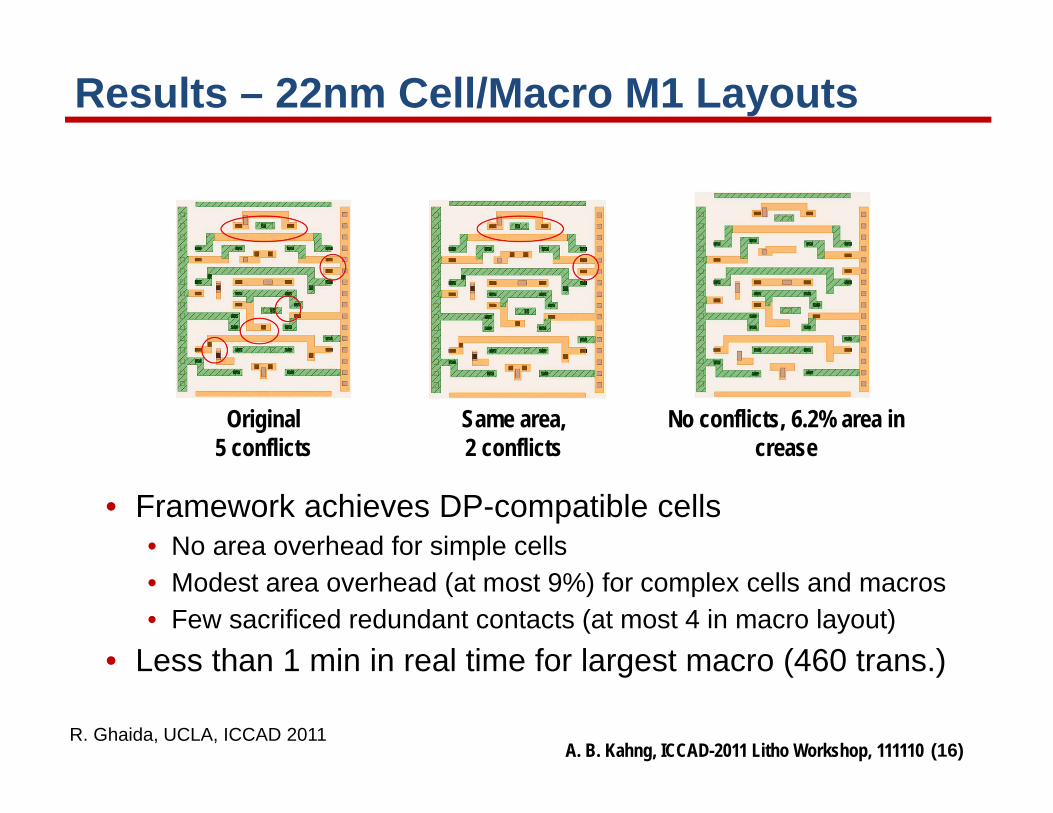
Results – 22nm Cell/Macro M1 Layouts
• Framework achieves DP-compatible cells• No area overhead for simple cells• Modest area overhead (at most 9%) for complex cells and macros• Few sacrificed redundant contacts (at most 4 in macro layout)
• Less than 1 min in real time for largest macro (460 trans.)
No conflicts, 6.2% area increase
Original 5 conflicts
Same area, 2 conflicts
R. Ghaida, UCLA, ICCAD 2011

(17)A. B. Kahng, ICCAD-2011 Litho Workshop, 111110
Triple Patterning for 14nm Dense M1
• Leverages 3-color stitching capability• Uses existing infrastructure for 2-coloring
(Any DP decomposition will work)• Supports different values for TT, TS, and SS spacing rules
S = W = 28nmTT = TS = 60nm, SS = 84nm (3x pitch relax.)
R. Ghaida, UCLA, ICCAD 2011

(18)A. B. Kahng, ICCAD-2011 Litho Workshop, 111110
UT Austin TPL Decomposition Flow
Decomposition Graph Construction
Semi-Definite Programming
Bridge Computation
Layout Graph Simplification
B. Yu et al., Univ. of Texas, ICCAD 2011
Triple PatterningProblem
Optimization Flow
• TPL reduces native conflicts• TPL is NP-Hard, ILP is slow• 140x speed-up using SDP
approximation vs. ILP

(19)A. B. Kahng, ICCAD-2011 Litho Workshop, 111110
Multi-Modal Variability in SADP• Different variabilities for different implementations
Copper
ManrdelSpacer
block
gap
DielectricM 0.5M S 0.5M
0.5B
M-BM-B
0.5M
S
0.5B
Feature Variance (2) (nm)Metal CD by mandrel sM
2 2.0
Metal CD by gap sM2+(2sS)2 3.3
Metal CD by wide mandrel+block (0.5sM)2+sM-B2+(0.5sB)2 8.1
Metal CD by wide gap+block (0.5sM)2+sS2+sM-B
2+(0.5sB)2 8.2
K. Jeong Ph.D. thesis, UCSD 2011

(20)A. B. Kahng, ICCAD-2011 Litho Workshop, 111110
• SADP shows more sensitivity tighten spacer control spec Spacer thickness variation is ~1/3 of mask overlay control• P-DE/DP shows least sensitivity lessen alignment spec
Maximum Crosstalk-Induced Delay
-6%-4%-2%0%2%4%6%8%
10%
Cro
ssta
lk D
elay
Var
iatio
n (%
)
Overlay Error (S)
P-DE/DPN-DE/DPP-SADPN-SADP

(21)A. B. Kahng, ICCAD-2011 Litho Workshop, 111110
UT Austin Graph-Based SADP Decomposition
Ban et al., Univ. of Texas, DAC 2011
Grouping, merging and coloring
Remove core mask violation using
trim mask
remove conflicts by re-grouping nodes in
conflict graph
Generation of assist mandrel
(22)
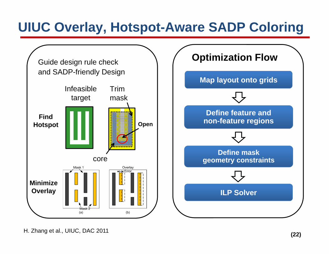
UIUC Overlay, Hotspot-Aware SADP Coloring
H. Zhang et al., UIUC, DAC 2011
Map layout onto grids
Define feature and non-feature regions
Define mask geometry constraints
ILP Solver
Optimization Flow
Find Hotspot
Minimize Overlay
Trim mask
Open
core
Infeasible target
Guide design rule check and SADP-friendly Design

(23)A. B. Kahng, ICCAD-2011 Litho Workshop, 111110
NL NL NR NRWLWL
VDD
VDDVSS
VSSBLB
BL
UCSD 2007-2008 IAL SRAM Bitcell Design
PG1
PU1
PD1PG2
PU2
PD2
VDD
VSSBLB BL
WL
NL NR
PG1
PG2
PD2
PD1
PU2
PU1
Schematic Layout Micrograph
• Our conclusions in 2008: very large area penalty (40+ %?) for logic standard cells – especially, migration of M1 layouts was problematic Kwangok Jeong stopped working on this
• However, Periodic Structures seems to be working on this, and Owa-san’s talk this morning inspires new attention!
PG1
PU1
PD1PG2
PU2
PD2

(24)A. B. Kahng, ICCAD-2011 Litho Workshop, 111110
Future Needs and Directions (1)• Which router is MPL-friendlier: gridded or gridless?
• Gridded routing: fewer odd cycles but faces routability issues• Gridless routing: good routability but introduces large-area odd cycles
• Fix routability estimation• Global router’s prediction of routability is harmed by MPL increases design iterations and TAT
• Trimodal variation mitigation for TPL • Odd-cycle fix methodology: floorplan, reroute, stitch…• Impact of stitching on reliability DRs? E.g., EM:
• 20nm logic node will see shorter, narrower wires• Should stitching to avoid color conflict be more acceptable?
• Algorithms for incremental (ECO) MPL layout• Orthogonal: still more DAM (design criticality-aware
DoseMap, overlay sequencing, etc.) and MAD

(25)A. B. Kahng, ICCAD-2011 Litho Workshop, 111110
Future Needs and Directions (2)• Basic, definitive tradeoff studies to determine costs,
benefits of MPL design methodology options• Cell-level coloring? No coloring at cell-level, but chip-level
coloring? Only coloring of pins and obstacles, with chip-level color-aware routing? …
• How should timing modeling and signoff tools recapture margin?
• SADP vs. LELE vs. DDL vs. LCL tradeoffs: DRC complexity vs. area overheads, layout methodology, signoff, variability, reliability, etc.
• Framework for “rules to design” what-if studies (~UCLA DRE)• “Theoretical” foundations still needed as well
• Ground “rules” to achieve correct MPL layouts with min overhead
• DRC-like layout compliance check with min overhead• …

(26)A. B. Kahng, ICCAD-2011 Litho Workshop, 111110
Acknowledgments
Many people generously provided inputs, slides, and other help to put together this talk!
1. Chul-Hong Park and Kwangok Jeong, Samsung2. Puneet Gupta and Rani Ghaida, UCLA3. Hongbo Zhang and Martin D.F. Wong, UIUC4. David Z. Pan, UT Austin5. Tuck-Boon Chan and Jingwei Lu, UCSD

A. B. Kahng, ICCAD-2011 Litho Workshop, 111110
Thank You

A. B. Kahng, ICCAD-2011 Litho Workshop, 111110
Backup Slides
(29)A. B. Kahng, ICCAD-2011 Litho Workshop, 111110
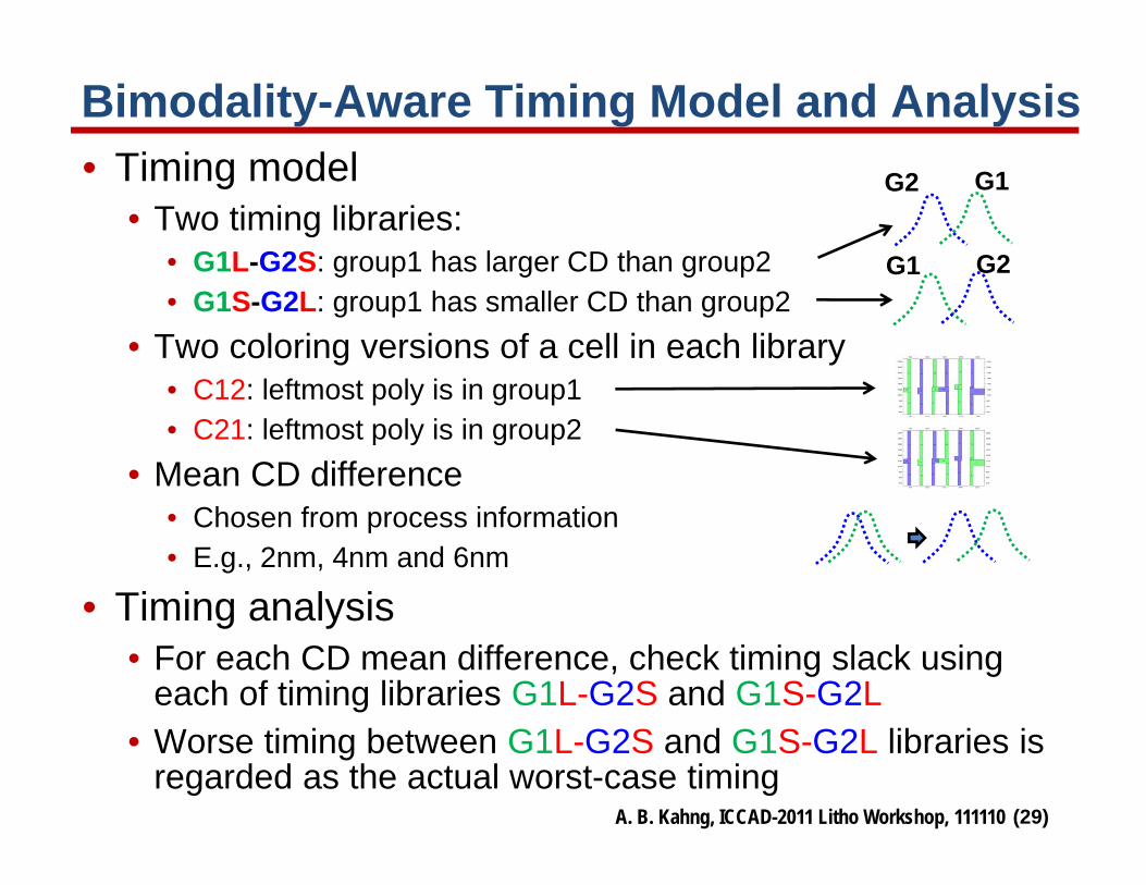
Bimodality-Aware Timing Model and Analysis• Timing model
• Two timing libraries: • G1L-G2S: group1 has larger CD than group2• G1S-G2L: group1 has smaller CD than group2
• Two coloring versions of a cell in each library• C12: leftmost poly is in group1• C21: leftmost poly is in group2
• Mean CD difference• Chosen from process information• E.g., 2nm, 4nm and 6nm
• Timing analysis• For each CD mean difference, check timing slack using
each of timing libraries G1L-G2S and G1S-G2L• Worse timing between G1L-G2S and G1S-G2L libraries is
regarded as the actual worst-case timing
G1G2
G2G1

(30)A. B. Kahng, ICCAD-2011 Litho Workshop, 111110
Variability Vs. Mask Assignments• Block mask patterns that define line edge should be avoided
• Patterns by mandrel vs. patterns by gap• Still exists bimodality between A and B• Important signal nets should be generated by mandrel
Target metalpattern
With overlay error
No CD variationCD variation
Final pattern
Line edges definedby only spacers
block mask (yellow) defines line edges
AB Coloring1 Coloring2
A < B A > B
(31)
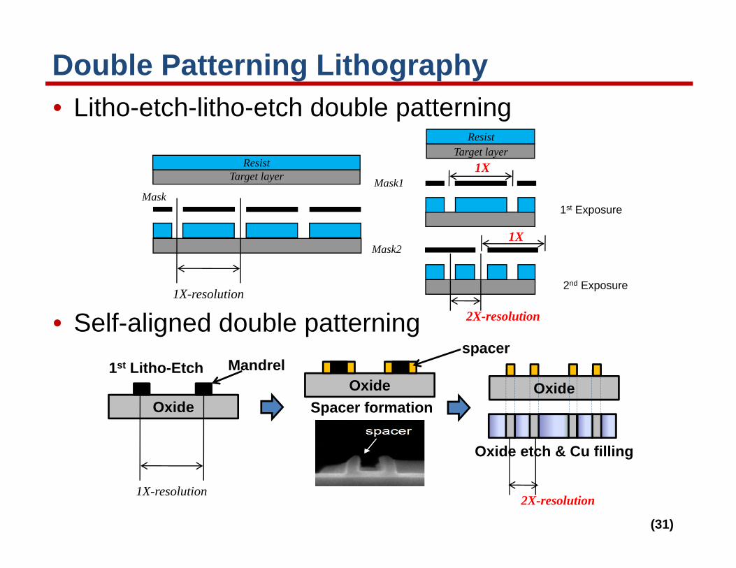
Double Patterning Lithography• Litho-etch-litho-etch double patterning
• Self-aligned double patterning
Target layerResist
1st Exposure
2nd Exposure
Mask1
Mask2
Target layerResist
Mask
1X-resolution
1X
2X-resolution
1X
Oxide
1st Litho-EtchOxide
Spacer formation
Oxide etch & Cu filling
OxideMandrel
spacer
1X-resolution2X-resolution

(32)A. B. Kahng, ICCAD-2011 Litho Workshop, 111110
BEOL Design-Level Analysis Framework• Overlay-aware extraction flow
1. Design GDSTOP.GDS
Initial GDS
AES core with NanGate 45nm Tech.
2. Split GDS
Base GDS Sub-GDS1
Sub-GDS2
DPL layersNon-DPL layers 3. PatternDecomposition
Sub-GDS1-1
Sub-GDS1-2
Sub-GDS2-1
Sub-GDS2-2
ILP-based min cost coloring(Kahng et al. ICCAD08)
Coloring and Splitting
SUB2.GDSSUB1.GDS
4. Shift and Merge(Cadence Virtuoso)
Shifting and Merging
SUB1 (x1, y1)TOP.GDS
SUB2 (x2, y2)
TOP.GDS
TOP.GDS
5. Resize and Extraction(Synopsys Hercules, Star-RCXT) Resizing