multiple realities: video projection in the tomb of … papers/cain_ramsses_ii.pdfmindscapes, vr and...
TRANSCRIPT
Mindscapes, VR and Cultural Landscapes Maurizio Forte (Editor)
1
Multiple Realities: Video Projection in the Tomb of Ramsses II
Kevin Cain, Philippe Martinez
INSIGHT—Institute for Study and Integration of Graphical Heritage Techniques
768 Brannan Street San Francisco CA 94103 e-mail: [email protected]
Abstract Here we present a new approach to archaeological reconstruction, in which we project digitally reconstructed iconography within a damaged Egyptian tomb. Combining video projection, computer animation, and digital compositing, a kind of ‘plural space’ is generated in the tomb’s burial chamber; this work is designed to enable visitors to view elements that were destroyed in antiquity. Also, we suggest that the act of projecting computer graphics reconstructions onto the walls of the tomb mirrors the ritual animation of the tomb’s inscriptions during the Egyptian ‘opening of the mouth’ ceremony. Our applica-tion is grounded in art installation, traditional archaeology, and the use of computers as theatre.
Keywords: 3D scanning, archaeology, reconstruction, Ramsses II, Egypt
1. Overview of the project
This paper briefly describes an effort to reconstruct the damaged tomb of Ramsses II (KV7) via computer animation and video projection. In our 2003 pilot pro-ject, we a) identified damaged inscriptions in KV7, b) documented these areas with laser scanning, c) used the documentation to develop a 3D reconstruction, and d) projected the resulting images onto the damaged inscrip-tions in the tomb. In order to explore our workflow, in the sections below we examine each step in the process. To give some context, we begin with a general introduc-tion to our work in KV7 and detail some of the technical details underlying our reconstruction technique.
1.1 Introduction -- The Tomb of Ramesses II (KV7)
The tomb of Ramsses II is one of the largest subter-ranean structures to have been created by the ancient Egyptians and one of the most impressive tombs erected in the Valley of the Kings, a site that has been recog-nized as World Heritage by UNESCO. The Valley as a whole is a site that continues to suffer from its success and the millions of visitors it receives every year. KV7, while closed to visitors, brings mixed emotion to its beholder in its present state. It was built near the famous tomb of Tutankhamun in a location that was revealed to be a poor choice in two principal aspects. While it was chosen for the apparent quality of the limestone in this area, the beauty of which is well exemplified by the quality of the carved raised reliefs decorating the outer
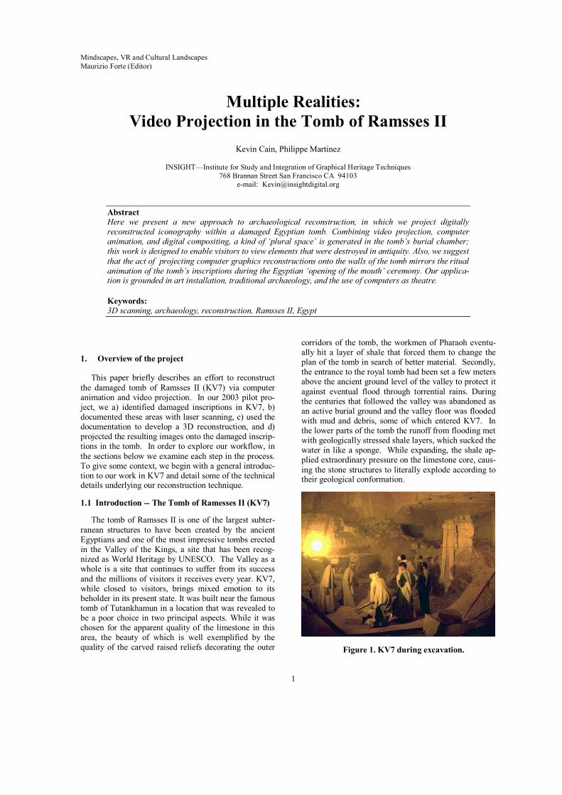
corridors of the tomb, the workmen of Pharaoh eventu-ally hit a layer of shale that forced them to change the plan of the tomb in search of better material. Secondly, the entrance to the royal tomb had been set a few meters above the ancient ground level of the valley to protect it against eventual flood through torrential rains. During the centuries that followed the valley was abandoned as an active burial ground and the valley floor was flooded with mud and debris, some of which entered KV7. In the lower parts of the tomb the runoff from flooding met with geologically stressed shale layers, which sucked the water in like a sponge. While expanding, the shale ap-plied extraordinary pressure on the limestone core, caus-ing the stone structures to literally explode according to their geological conformation.
Figure 1. KV7 during excavation.
2
The archaeological exploration of the tomb was com-plicated by the need to excavate a huge quantity of run-off mud and debris, material which had hardened to the consistency of concrete. The tomb is now almost totally emptied from its muddy encasing and is receiving the focused attention of restorers working under Dr. Chris-tian Leblanc. Work is proceeding to restore both the structure of the tomb as well as its decoration. While KV7 is not yet open to the public, its location in the neighbourhood of the tomb of Tutankhamun and the fact that it is the tomb of Ramesses the Great has turned it into an attraction worth mentioning to the passing groups of tourists. This situation tends to make it clear that once opened it should become one of the highlights of a visit to the Valley.
However, Christian Leblanc fears the actual state of the monument might belie its ancient glory and deceive its visitors. In response, we structured our work in such a way that site visitors could better understand KV7. Three requirements were identified:
1. Dr. Leblanc needed a precise 3D scan of the architecture of the tomb to prepare for its strengthening and restoration. Also, since the preparation of documentation needed for the scientific publication would take a using clas-sical analogue techniques, we became inter-ested in ways to use the 3D scan archive to create the documents needed for scholarly publication. It was thus decided that the rem-nants of the tomb’s very shallow decoration would need to be scanned in a very precise manner to facilitate an automated digital epi-graphic survey. This novel approach is some-thing that many Egyptologists have been day-dreaming of for decades without any real hope of achieving. When discussion began, a 3D scanner able to survey such fine relief did not in fact exist. At the time we began to envision the project we instead were evaluating differ-ent approaches, mainly structured light and short range laser scanning. Digital photogra-phy was also to be used to survey the actual state of the wall surfaces and be used as realis-tic textures of the 3D models, to be exploited in the scientific publication of the monument.
2. Apart from this scientific endeavour that would be the logical and necessary output of the decade of hard work already put in the pro-ject by Christian Leblanc’s team, we were also asked to think about different ways to bring the tomb back to its ancient glory. At the least, we hoped to be able to pass an idea of the complexity and beauty of the tomb’s archi-tectural and decorative program as well as of its history and importance to its future visitors.
3. Our work should thus lead to the 2D recon-struction of the polychrome decoration from
parallels gathered in contemporaneous nearby tombs, a reconstruction that would not only be shown on screen or paper but that should be projected on the walls of the destroyed burial chamber. In this way, a visit of the tomb would be turned into a three dimensional digi-tal sound and light show, its beholder being plunged into the ancient brilliance of the place after having been turned into the witness of its actual desecrated state, remnant shadows of its ancient glory.
Even if the context thus presented is necessary to un-derstand the scope of the ongoing archaeological re-search that underlies our digital efforts, for the purposes of this paper we will concentrate on 3D laser scanning and projection. NOTE: for an informal day-by-day summary of field work in 2003, see: www.insightdigital.org; please click on Field Journal 2003
1.2 Documentation Goals
Our 2003 field work involved a team of ten. Work was carried out in the Valley of the Kings on the Nile’s West bank in Thebes, Egypt, through official invitation of the Egyptian government (Supreme Council of An-tiquities) and of Christian Leblanc, Research Director for the CNRS and actual field director of the French archaeological mission in Western Thebes. The main aim was to prepare scientific documents for publication, as well as to guide decisions in the context of current restoration and presentation work.
There are three facets to this documentation effort:
1. 3D Laser Scanning. During our three weeks of field work, we gathered over half a billion detailed measurements of Ramesses II’s tomb and temple using three laser scanning systems with standard PCs as control systems.
2. High-resolution digital photography. Our photographers shot over one thousand docu-mentary images of the tomb during our field work. A laptop was used to preview these high resolution photographs in the tomb, and other systems were used to archive the huge number of images shot with Canon D-60 and Nikon D-100 cameras.
2. Video Projection in Ramesses II’s burial chamber. Digital artists used a desktop PC to project a digital restoration onto the walls of the tomb’s burial chamber. This was the first ‘digital restoration’ of its kind that we have at-tempted.
These three facets were led according to two separate but complementary fields of research. In 2002, we were called on site to scan the remnants of a granite colossus
3
of the king that used to stand in front of the second py-lon of the Ramesseum. The colossus has rested on its back across the main axis of the temple since the medie-val era and plays an active part in the romantic aspect of this ruin. Nevertheless since it is also blocking the main axis of the site, the current state of the colossus prevents visitors from understand the Ramesseum’s architecture. In an effort to present and preserve the site in a modern way, the Franco-Egyptian mission working on site was asked to prepare a project for the restoration and re-erection of the colossus. Therefore, the most important fragments were scanned last year with a Mensi SOISIC scanner and a virtual reconstruction was achieved against a template using a 3D scan of the best preserved of the two Memnon colossi. If the results appeared inter-esting and new, they were not as helpful as first thought in judging the feasibility and interest of a physical re-construction. The virtual colossus needed to be judged against its real setting and a model of the temple in its actual state was therefore necessary. We thus decided to ask for the help of Mensi and the generosity of EdF to secure the use of a fast 3D long range scanner that would enable us to survey the architectural remnants of the mortuary temple for the King of Kings.
2. Field Sampling Discussion
Below we would like to consider field sampling is-sues related to our January 2003 fieldwork, including practical problems and solutions encountered during our laser scanning fieldwork in Egypt. For this work, our team of ten used both the Minolta 910 and Mensi GS-100 laser scanners. A Minolta 700 scanner was also on hand, which was used primarily for testing. For the purposes of this report, after a presentation of our on site test of the GS-100 scanner, we shall concentrate on the use of the Minolta 910 scanner since it relates to our specific area of interest for digital epigraphic archiving.
2.1 Scanning in KV7
Our scanning project in KV7 required optimization for two diametrically opposed factors: quality and speed. The slight wall relief was in many cases sub-millimeter and therefore required high resolution, while the enormous amount of wall space demanded a scan-ning approach that was fast and simple. Acknowledging the difficulties, the following requirements were laid out.
2.2 Acquisition Details & Statistics
Resolution • In 2002, we carried out a number of trials
in KV7 with the Minolta 700, a precursor to the Minolta 910. While results were in some cases quite satisfactory for docu-menting general epigraphic features, the 200x200 sample resolution was ulti-
mately not sufficient to properly docu-ment the small carvings and hieroglyphs present in the tomb.
• Therefore, resolution became a key con-cern and we became convinced that we required sub-millimeter accuracy throughout our documentation of KV7 in order to capture necessarily details.
Speed of Use • Since access to the tomb is limited, we
were concerned with finding a way to maximize the total wall area we were able to scan during our field work.
• Since the Minolta 900’s scan time is fixed, maximizing wall coverage de-pended mainly on:
o Using a medium-angle lens o While we needed to move the
scanner quickly throughout the tomb in order to cover ground efficiently, we also needed to keep the scanner perpendicular to the wall in order to maximize quality (see discussion in Sec-tion 2 above).
Therefore: • We designed and built a simple rig that
allowed the scanner to track vertically a set distance from the wall to be scanned—see Section D, “Methods”, be-low This approach provided a significant improvement over a tripod mount in be-ing able to maintain a consistent scan an-gle.
Robustness
• The punishing environment of KV7 is no-toriously dusty, hot, and difficult to work in.
• Therefore we needed a scanner that could operate several hours a day in these con-ditions.
2.3 Analysis of the Minolta 910
Our work with the Minolta 910, as described above, allowed us to successfully complete the scope of work we planned. Following is a summary of the machine’s performance during our field work:
Advantages: • The Minolta 910 operated flawlessly in
the difficult heat/dust environment of the tomb.
4
• The portability of the scanner allowed us to set up scan viewpoints reasonably quickly and easily.
Disadvantages:
• The presence of 3D data artifacts (de-scribed below) incurred processing time to correct.
• Standard optical triangulation deficien-cies (see below) must be taken into con-sideration, as with any laser scanner that uses this method of 3D range finding.
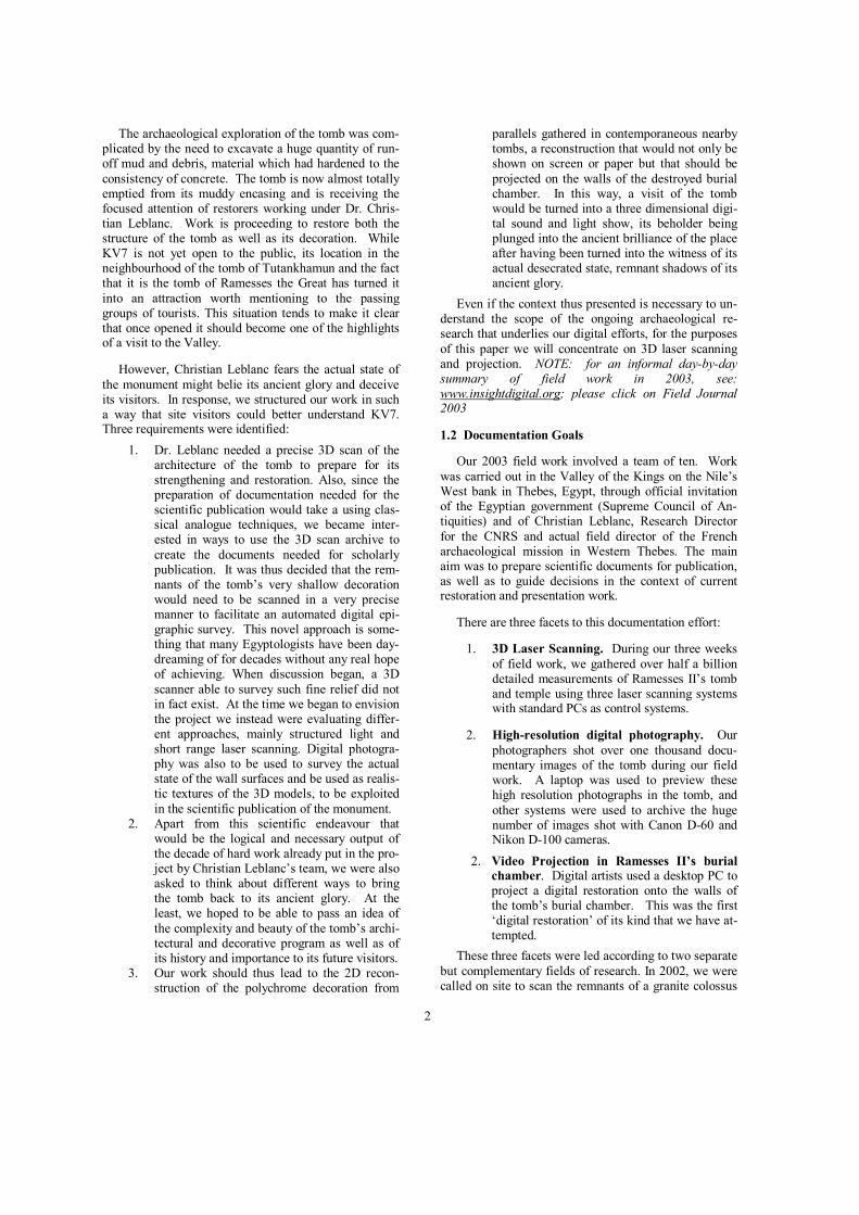
Figure 2. Kevin Cain working with the Minolta 910 in KV7.
Note the specially designed transparent plate on the bottom of the scanner—this on-site modification proved necessary in order to provide stability during shooting,
the metal base of the scanner not being sturdy enough to avoid transmitting vibration during scanning.
Statistics, timing, efficiency
The Minolta 910 scanner captures: • 640x480 3D measurements per scan • Scan time is apprx. 2.5 seconds per scan • Apprx. 5 second transfer time is needed
following scan (either via SCSI or via PCMCIA flashcard)
• Color is captured at the scan resolution of 640x480
Operating Notes: • The Minolta 910’s depth of field is fixed
at 200mm—which means it can only re-
cord depth readings within a 200mm Z-depth. Points that fall outside of this depth of field are simply discarded.
o In KV7, the planar nature of the walls posed no problem what-soever for the limited depth of field in the scanner. However, for more dimensional objects (such as our 2002 field work for the colossus of Ramesses II) the limited depth of field re-quires careful viewpoint plan-ning in order to capture the en-tire form.
• The Minolta can be controlled remotely by a computer (via SCSI) or directly from the unit’s back panel
o For our field work, we found it fastest to use the scan controls directly on the back panel. Not only did it speed up the saving of data (which was written to PCMCIA cards) but it obviated the need for a control computer which would have had to move along with the scanner and tri-pod/rig in very difficult sur-roundings.
Field Mission Statistics:
• Average number of scans/hour: 14 • Average distance between adjacent
points: 0.3 – 0.6 mm • Total number of scans: 2300+
2.4 Techniques—Mounting and Shooting with the Minolta 900
During tests, we mounted the Minolta 900 onto a special tripod, as shown above and below. Tripod set-ups were the fastest we clocked, but the tilting angles required by the tripod introduced prominent 3D artifacts (the nature of these artifacts is discussed below).
5
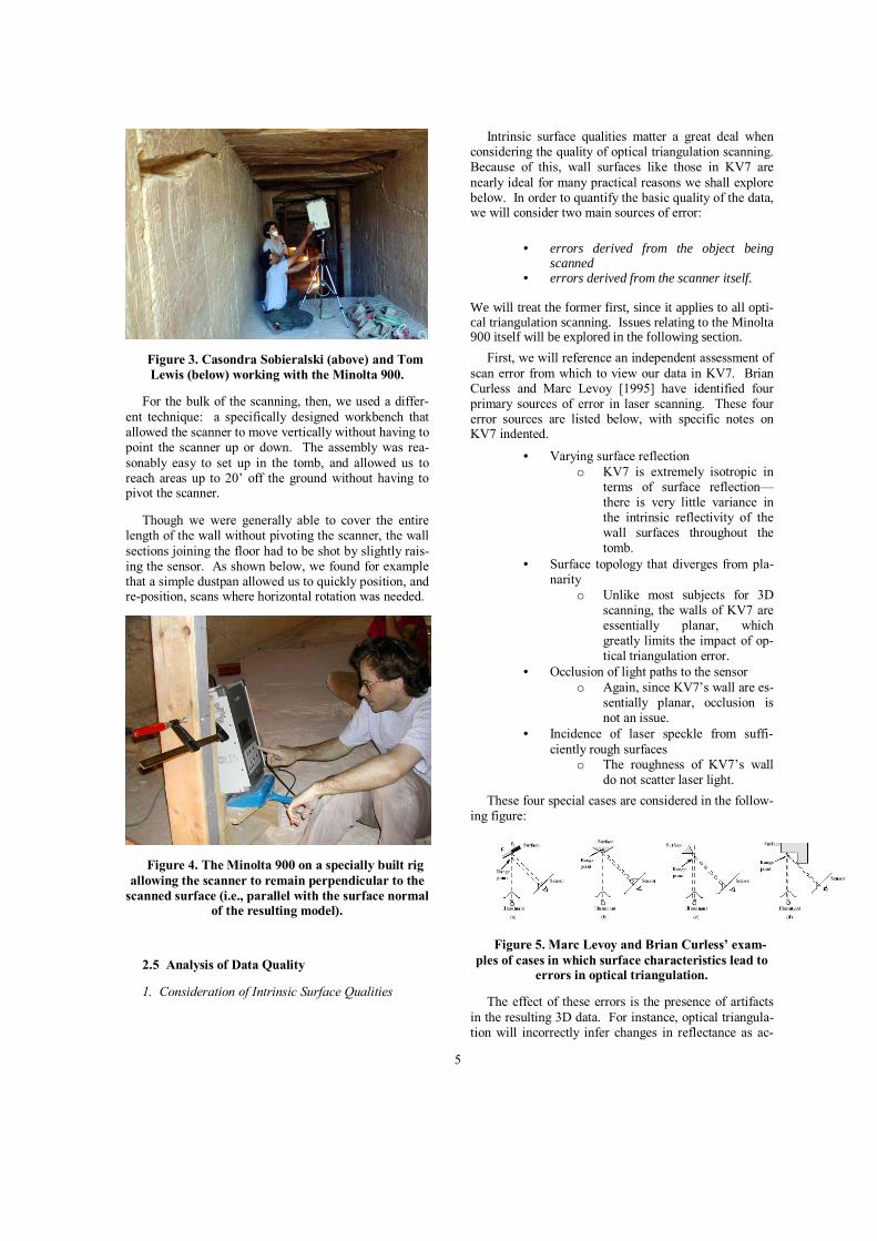
Figure 3. Casondra Sobieralski (above) and Tom Lewis (below) working with the Minolta 900.
For the bulk of the scanning, then, we used a differ-ent technique: a specifically designed workbench that allowed the scanner to move vertically without having to point the scanner up or down. The assembly was rea-sonably easy to set up in the tomb, and allowed us to reach areas up to 20’ off the ground without having to pivot the scanner.
Though we were generally able to cover the entire length of the wall without pivoting the scanner, the wall sections joining the floor had to be shot by slightly rais-ing the sensor. As shown below, we found for example that a simple dustpan allowed us to quickly position, and re-position, scans where horizontal rotation was needed.
Figure 4. The Minolta 900 on a specially built rig allowing the scanner to remain perpendicular to the
scanned surface (i.e., parallel with the surface normal of the resulting model).
2.5 Analysis of Data Quality
1. Consideration of Intrinsic Surface Qualities
Intrinsic surface qualities matter a great deal when considering the quality of optical triangulation scanning. Because of this, wall surfaces like those in KV7 are nearly ideal for many practical reasons we shall explore below. In order to quantify the basic quality of the data, we will consider two main sources of error:
• errors derived from the object being scanned
• errors derived from the scanner itself. We will treat the former first, since it applies to all opti-cal triangulation scanning. Issues relating to the Minolta 900 itself will be explored in the following section.
First, we will reference an independent assessment of scan error from which to view our data in KV7. Brian Curless and Marc Levoy [1995] have identified four primary sources of error in laser scanning. These four error sources are listed below, with specific notes on KV7 indented.
• Varying surface reflection o KV7 is extremely isotropic in
terms of surface reflection—there is very little variance in the intrinsic reflectivity of the wall surfaces throughout the tomb.
• Surface topology that diverges from pla-narity
o Unlike most subjects for 3D scanning, the walls of KV7 are essentially planar, which greatly limits the impact of op-tical triangulation error.
• Occlusion of light paths to the sensor o Again, since KV7’s wall are es-
sentially planar, occlusion is not an issue.
• Incidence of laser speckle from suffi-ciently rough surfaces
o The roughness of KV7’s wall do not scatter laser light.
These four special cases are considered in the follow-ing figure:
Figure 5. Marc Levoy and Brian Curless’ exam-ples of cases in which surface characteristics lead to
errors in optical triangulation.
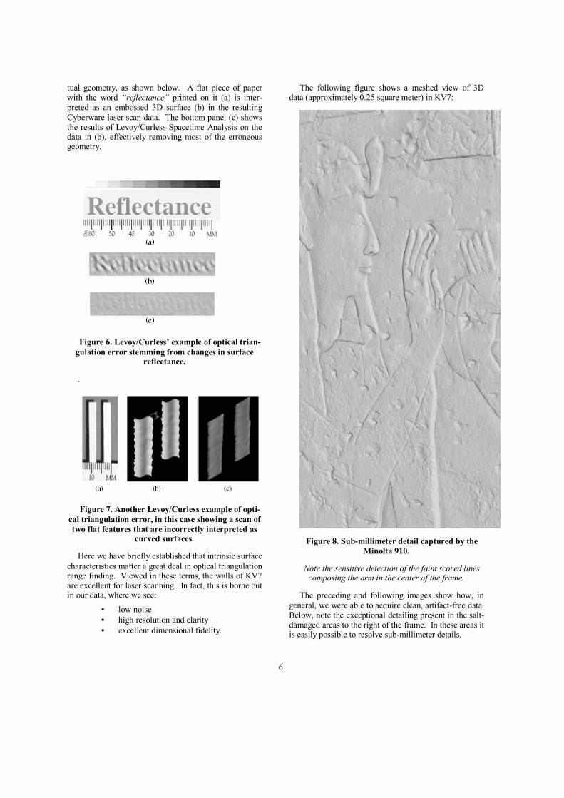
The effect of these errors is the presence of artifacts in the resulting 3D data. For instance, optical triangula-tion will incorrectly infer changes in reflectance as ac-
6
tual geometry, as shown below. A flat piece of paper with the word “reflectance” printed on it (a) is inter-preted as an embossed 3D surface (b) in the resulting Cyberware laser scan data. The bottom panel (c) shows the results of Levoy/Curless Spacetime Analysis on the data in (b), effectively removing most of the erroneous geometry.
Figure 6. Levoy/Curless’ example of optical trian-gulation error stemming from changes in surface
reflectance.
.
Figure 7. Another Levoy/Curless example of opti-cal triangulation error, in this case showing a scan of two flat features that are incorrectly interpreted as
curved surfaces.
Here we have briefly established that intrinsic surface characteristics matter a great deal in optical triangulation range finding. Viewed in these terms, the walls of KV7 are excellent for laser scanning. In fact, this is borne out in our data, where we see:
• low noise • high resolution and clarity • excellent dimensional fidelity.
The following figure shows a meshed view of 3D data (approximately 0.25 square meter) in KV7:
Figure 8. Sub-millimeter detail captured by the Minolta 910.
Note the sensitive detection of the faint scored lines composing the arm in the center of the frame.
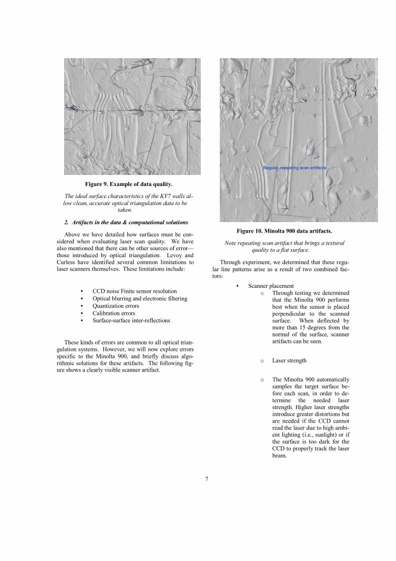
The preceding and following images show how, in general, we were able to acquire clean, artifact-free data. Below, note the exceptional detailing present in the salt-damaged areas to the right of the frame. In these areas it is easily possible to resolve sub-millimeter details.
7
Figure 9. Example of data quality.
The ideal surface characteristics of the KV7 walls al-low clean, accurate optical triangulation data to be
taken.
2. Artifacts in the data & computational solutions
Above we have detailed how surfaces must be con-sidered when evaluating laser scan quality. We have also mentioned that there can be other sources of error—those introduced by optical triangulation. Levoy and Curless have identified several common limitations to laser scanners themselves. These limitations include:
• CCD noise Finite sensor resolution • Optical blurring and electronic filtering • Quantization errors • Calibration errors • Surface-surface inter-reflections
These kinds of errors are common to all optical trian-gulation systems. However, we will now explore errors specific to the Minolta 900, and briefly discuss algo-rithmic solutions for these artifacts. The following fig-ure shows a clearly visible scanner artifact.
Figure 10. Minolta 900 data artifacts.
Note repeating scan artifact that brings a textural quality to a flat surface.
Through experiment, we determined that these regu-lar line patterns arise as a result of two combined fac-tors:
• Scanner placement o Through testing we determined
that the Minolta 900 performs best when the sensor is placed perpendicular to the scanned surface. When deflected by more than 15 degrees from the normal of the surface, scanner artifacts can be seen.
o Laser strength
o The Minolta 900 automatically
samples the target surface be-fore each scan, in order to de-termine the needed laser strength. Higher laser strengths introduce greater distortions but are needed if the CCD cannot read the laser due to high ambi-ent lighting (i.e., sunlight) or if the surface is too dark for the CCD to properly track the laser beam.
8
With GSI, we have explored different ways to quan-tify these artifacts. Visualization data was added for Minolta data within GSI’s software in order to see ver-tex and face normals. When displayed:
• Face normals from the Minolta data ap-pear to vary ~15 degrees, which in turn causes vertex normal problems.
o Vertex normals are more accu-rate than face normals, since they are averaged around the incident faces.
The apparent difficulty with face normals seems to account for the presence of these artifacts. The above description also suggests computational solutions:
• Global smoothing of vertex normals (without modifying the underlying ge-ometry) remove the artifact
• A very light smoothing algorithm could be used to detect and erase these signa-ture artifacts where present. Further work is in progress regarding implemen-tation of this approach.
3. Consideration of other error sources
In addition to the above, there are other sources of er-ror deserving of consideration.
• Inverse-square law effects o Since light falls off at the
square of its distance from a given object, this basic property of physics has an effect on the return of the laser light to the CCD. However, since the Mi-nolta 900 operates at short dis-tances from the subject of the scan, these effects are not sig-nificant for this scanner.
• Meshing errors o Creating a 3D mesh from a
point cloud requires specific in-formation about the viewpoint from which a scan was taken. Even when this information is known, there are a variety of approaches for generating sur-face meshes, and each can be considered to contribute its own unique errors.
2.6 Defining ‘Resolution’ in 3D Scanning
Resolution is unquestionably the primary metric for all 3D scanning. Nonetheless this metric eludes quantifi-cation. Everyone who works with laser data is familiar with the vagaries of defining “resolution”. Below we
offer some definitions on which to build our concept of “Adjusted Resolution Index”, or ARI, which will then be used as the foundation for a proposed technique.
1. Definitions:
• Distance to Point (DP): the linear distance from the lens to the point being measured, in millimeters.
• Point Interval Value (PIV): the averaged minimal regular spacing of 3D points for a set of measurements, in millimeters, forming the effective resolution limit for edge-length reso-lution, below.
• Point accuracy (PA): the intrinsic ability of a scanner to resolve a point in space, independ-ent of the distance between points. Point ac-curacy is subject to inverse-square law falloff, as below:
• Point falloff (PFO): erosion of point accuracy as DP increases, according to the inverse square law, lens quality, and other effects.
• Maximal grid resolution (MGR): the UV framing grid used to define a given scan’s viewpoint.
For instance, consider the following scan: • PIV=1 mm • PA=.5 mm • MGR=10mm
While the grid resolution for this long range scan is set to 10mm, this spacing value will only be consistent for a plane extending in front of the scanner. (In the case of the GS-100, this would instead be a cylinder swept in XYZ space at a fixed distance from the pivoting GS-100 scan head.) Therefore, for non-conforming objects, the PIV will effectively change for each sample, creating much higher or lower values, some which may uninten-tionally dip below the scanner’s intrinsic accuracy limits (PA).
2. Computational Terminology (Intrinsic to Correla-tion)
Minimal edge length resolution (MELR): the aver-age linear distance between adjacent points in a point set
• Since adjacent vertices will be tesselated into triangular polys, edge length actually repre-sents a real limit to resolution.
ICP resolution (ICPR): the effective resolution to which ICP can generate meaningful solutions
* In most ICP approaches, edge length (delta from vertex location A to vertex location B) represents a real limit to the resolution of a merged point cloud.
9
o The GSI Studio approach al-lows registration of meshes at points other than vertices, ena-bling sub-edge-length registra-tion.
2.6.1 Confidence and Intrinsic Surface Characteris-tics
Since all laser data is dependent on the surface char-acteristics of real-world objects, there can be no objec-tive consideration of scan “resolution” without factoring in the intrinsic qualities of the scanned surface(s).
1. Composite Surfaces The above is complicated by composite materials, where specularity, color or lacunarity change across a "limb", as shown below. Computational sensitivity is especially required in optical triangulation systems, since color limbs across flat planes (i.e., black writing on a white sheet of paper) can in fact be interpreted as a Z dis-placement. (See notes below on Levoy's Space/Time Analysis for expansion) Reprocessing algorithms are needed to compensate for these artifacts.
Desired homogenous, isotropic surfaces
The scanned surfaces in KV7 were nearly ideal in terms of isotropism and surface characteristics. Specifi-cally, the walls of KV7 exhibit:
• Light surface color, excellent laser return (al-lowing minimal laser levels and therefore minimal noise/distortion).
• Extremely homogenous surface color. • Low specularity. • Nearly total control of ambient light. In the
same way that light-colored walls allowed the Minolta 900 to scan at lower laser power and therefore with less noise, the fact of KV7's un-derground location allowed nearly total con-trol of lighting.
2.6.2 Adjusted registration index (ARI)
As noted above, “resolution” is a term without a fixed identity for laser scan data. Therefore, we would like to suggest a new metric, called “adjusted registra-tion index” or ARI, for appropriately quantifying the actual registration of scan data,. Whereas “confidence” is generally expressed as a per-vertex value, here we suggest assigning ARI for a set of points.
1. Per-point values:
• Confidence scalar (Conf)r: 0 to 1 (0=scan an-gle parallel to given surface (perpendicular to normal), 1=scan angle perpendicular to given surface, parallel with normal)
• Gain threshold (Gain): 0 to 1 (0=device-dependent limit at which intrinsic light re-turn/ambient lighting blind the CCD to incom-ing sensor laser light, 1=perfect return of laser to CCD)
• Specularity scalar (Spec): 0 to 1 (0=nominal gain threshold, 1=perfect light return of laser to CCD)
1. Computing global ARI from a group of
points, 1…n:
2. On-Site Align and Merge
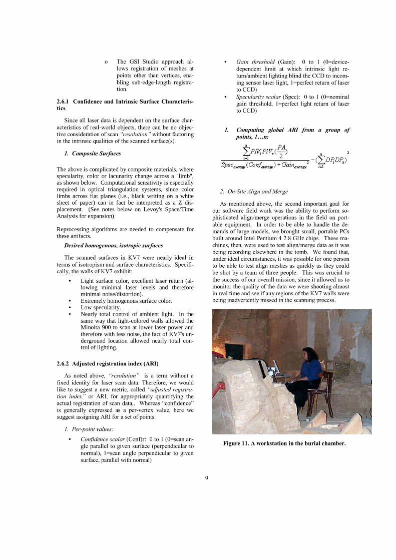
As mentioned above, the second important goal for our software field work was the ability to perform so-phisticated align/merge operations in the field on port-able equipment. In order to be able to handle the de-mands of large models, we brought small, portable PCs built around Intel Pentium 4 2.8 GHz chips. These ma-chines, then, were used to test align/merge data as it was being recording elsewhere in the tomb. We found that, under ideal circumstances, it was possible for one person to be able to test align meshes as quickly as they could be shot by a team of three people. This was crucial to the success of our overall mission, since it allowed us to monitor the quality of the data we were shooting almost in real time and see if any regions of the KV7 walls were being inadvertently missed in the scanning process.
Figure 11. A workstation in the burial chamber.
10
3. Projecting digital epigraphy within KV7
The previous sections describe the process we used to obtain a global 3D scan archive for KV7. Now we will examine a small part of that archive which serves as the basis for our digital reconstruction.
3.1 The iconographic program in KV7
“Whatever the case, one fact is sure: the decoration of the tomb was completed, as proved during the careful examination of all walls with remaining fragments of relief and painted decoration. The iconographic reper-toire was essentially the same as that in the tomb of Seti I. In addition to the traditional scenes of offering, the great funerary compilations find place of honour: the Litany of the Sun in the first corridor; the Book of Am-Duat and the Book of Gates divided over the walls of several corridors and chambers; the Opening of the Mouse Ritual in the fourth and the fifth corridors; the Book of the Cow Goddess of the Sky in the annex (N); select chapters of the Book of the Dead, accompanied by vignettes, on the walls of antechamber (I), and the annex (Q2). As in many of the royal tombs a shaft was present, cut between the corridor (D) and the "Chariot Room", but unlike other known shafts, its walls were decorated from the mouse downwards; notable on the east wall are scenes and texts relating to the twelfth division of the Book of the Am-Duat.”
- Dr. Christian LeBlanc, CNRS, director of field work in KV7.
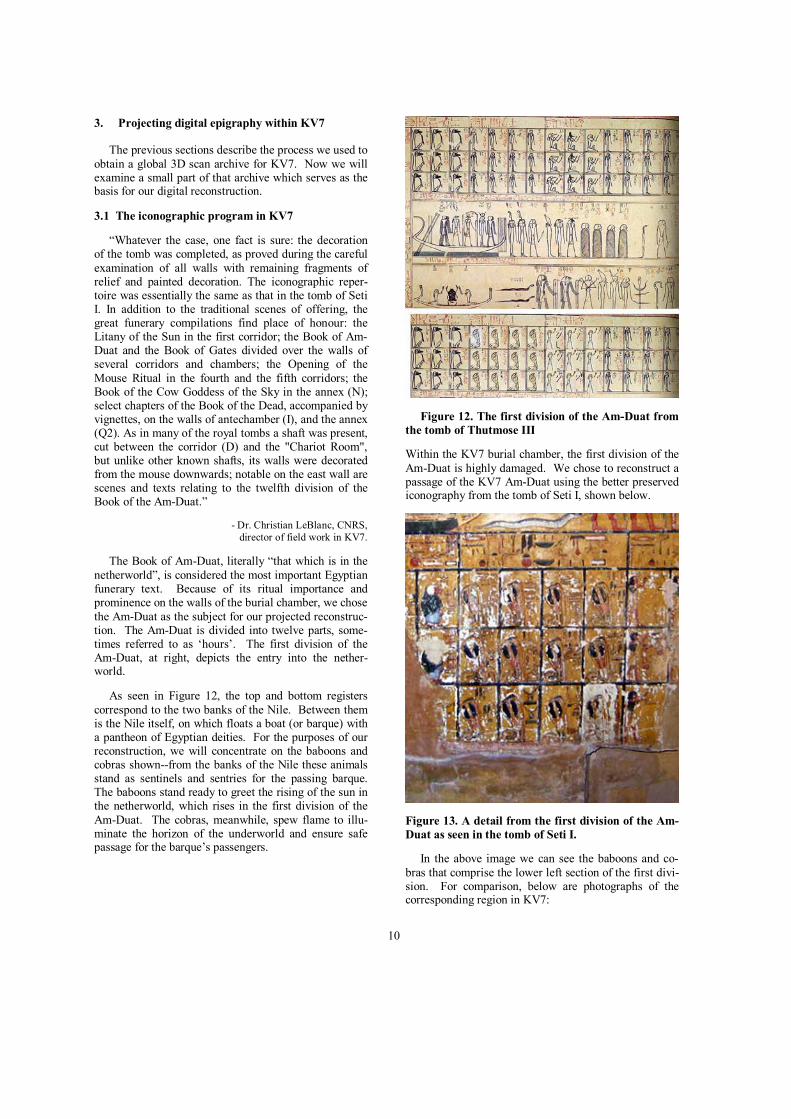
The Book of Am-Duat, literally “that which is in the netherworld”, is considered the most important Egyptian funerary text. Because of its ritual importance and prominence on the walls of the burial chamber, we chose the Am-Duat as the subject for our projected reconstruc-tion. The Am-Duat is divided into twelve parts, some-times referred to as ‘hours’. The first division of the Am-Duat, at right, depicts the entry into the nether-world.
As seen in Figure 12, the top and bottom registers correspond to the two banks of the Nile. Between them is the Nile itself, on which floats a boat (or barque) with a pantheon of Egyptian deities. For the purposes of our reconstruction, we will concentrate on the baboons and cobras shown--from the banks of the Nile these animals stand as sentinels and sentries for the passing barque. The baboons stand ready to greet the rising of the sun in the netherworld, which rises in the first division of the Am-Duat. The cobras, meanwhile, spew flame to illu-minate the horizon of the underworld and ensure safe passage for the barque’s passengers.
Figure 12. The first division of the Am-Duat from the tomb of Thutmose III
Within the KV7 burial chamber, the first division of the Am-Duat is highly damaged. We chose to reconstruct a passage of the KV7 Am-Duat using the better preserved iconography from the tomb of Seti I, shown below.
Figure 13. A detail from the first division of the Am-Duat as seen in the tomb of Seti I.
In the above image we can see the baboons and co-bras that comprise the lower left section of the first divi-sion. For comparison, below are photographs of the corresponding region in KV7:
11
Figure 14. Baboon detail, first division of the Am-Duat, KV7.
Similarly, fragments of the cobras are seen here:
Figure 15. Cobra detail, first division of the Am-Duat, KV7.
Figure 16. Comparison with the Am-Duat as seen in another Theban tomb.
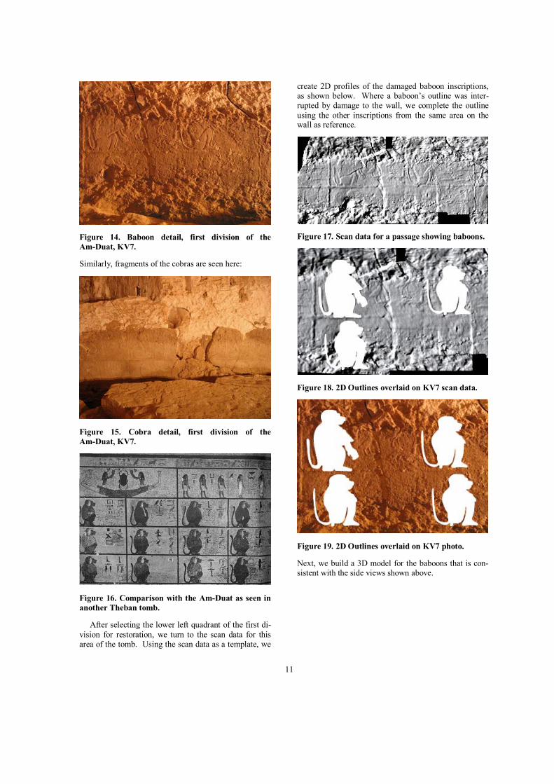
After selecting the lower left quadrant of the first di-vision for restoration, we turn to the scan data for this area of the tomb. Using the scan data as a template, we
create 2D profiles of the damaged baboon inscriptions, as shown below. Where a baboon’s outline was inter-rupted by damage to the wall, we complete the outline using the other inscriptions from the same area on the wall as reference.
Figure 17. Scan data for a passage showing baboons.
Figure 18. 2D Outlines overlaid on KV7 scan data.
Figure 19. 2D Outlines overlaid on KV7 photo.
Next, we build a 3D model for the baboons that is con-sistent with the side views shown above.
12
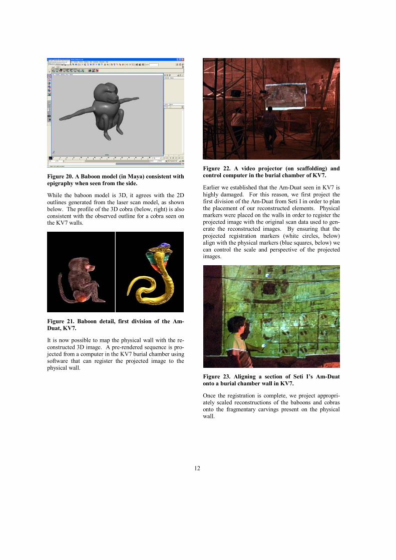
Figure 20. A Baboon model (in Maya) consistent with epigraphy when seen from the side.
While the baboon model is 3D, it agrees with the 2D outlines generated from the laser scan model, as shown below. The profile of the 3D cobra (below, right) is also consistent with the observed outline for a cobra seen on the KV7 walls.
Figure 21. Baboon detail, first division of the Am-Duat, KV7.
It is now possible to map the physical wall with the re-constructed 3D image. A pre-rendered sequence is pro-jected from a computer in the KV7 burial chamber using software that can register the projected image to the physical wall.
Figure 22. A video projector (on scaffolding) and control computer in the burial chamber of KV7.
Earlier we established that the Am-Duat seen in KV7 is highly damaged. For this reason, we first project the first division of the Am-Duat from Seti I in order to plan the placement of our reconstructed elements. Physical markers were placed on the walls in order to register the projected image with the original scan data used to gen-erate the reconstructed images. By ensuring that the projected registration markers (white circles, below) align with the physical markers (blue squares, below) we can control the scale and perspective of the projected images.
Figure 23. Aligning a section of Seti I’s Am-Duat onto a burial chamber wall in KV7.
Once the registration is complete, we project appropri-ately scaled reconstructions of the baboons and cobras onto the fragmentary carvings present on the physical wall.
13
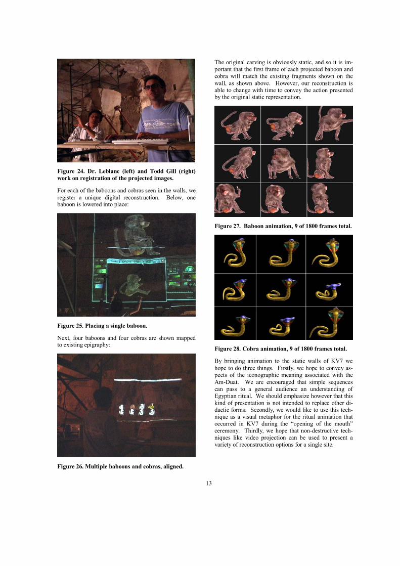
Figure 24. Dr. Leblanc (left) and Todd Gill (right) work on registration of the projected images.
For each of the baboons and cobras seen in the walls, we register a unique digital reconstruction. Below, one baboon is lowered into place:
Figure 25. Placing a single baboon.
Next, four baboons and four cobras are shown mapped to existing epigraphy:
Figure 26. Multiple baboons and cobras, aligned.
The original carving is obviously static, and so it is im-portant that the first frame of each projected baboon and cobra will match the existing fragments shown on the wall, as shown above. However, our reconstruction is able to change with time to convey the action presented by the original static representation.
Figure 27. Baboon animation, 9 of 1800 frames total.
Figure 28. Cobra animation, 9 of 1800 frames total.
By bringing animation to the static walls of KV7 we hope to do three things. Firstly, we hope to convey as-pects of the iconographic meaning associated with the Am-Duat. We are encouraged that simple sequences can pass to a general audience an understanding of Egyptian ritual. We should emphasize however that this kind of presentation is not intended to replace other di-dactic forms. Secondly, we would like to use this tech-nique as a visual metaphor for the ritual animation that occurred in KV7 during the “opening of the mouth” ceremony. Thirdly, we hope that non-destructive tech-niques like video projection can be used to present a variety of reconstruction options for a single site.
14
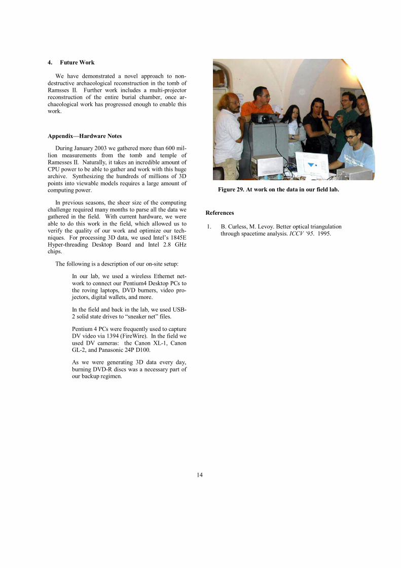
4. Future Work
We have demonstrated a novel approach to non-destructive archaeological reconstruction in the tomb of Ramsses II. Further work includes a multi-projector reconstruction of the entire burial chamber, once ar-chaeological work has progressed enough to enable this work.
Appendix—Hardware Notes
During January 2003 we gathered more than 600 mil-lion measurements from the tomb and temple of Ramesses II. Naturally, it takes an incredible amount of CPU power to be able to gather and work with this huge archive. Synthesizing the hundreds of millions of 3D points into viewable models requires a large amount of computing power.
In previous seasons, the sheer size of the computing challenge required many months to parse all the data we gathered in the field. With current hardware, we were able to do this work in the field, which allowed us to verify the quality of our work and optimize our tech-niques. For processing 3D data, we used Intel’s 1845E Hyper-threading Desktop Board and Intel 2.8 GHz chips.
The following is a description of our on-site setup:
� In our lab, we used a wireless Ethernet net-work to connect our Pentium4 Desktop PCs to the roving laptops, DVD burners, video pro-jectors, digital wallets, and more.
� In the field and back in the lab, we used USB-2 solid state drives to “sneaker net” files.
� Pentium 4 PCs were frequently used to capture DV video via 1394 (FireWire). In the field we used DV cameras: the Canon XL-1, Canon GL-2, and Panasonic 24P D100.
� As we were generating 3D data every day, burning DVD-R discs was a necessary part of our backup regimen.
Figure 29. At work on the data in our field lab.
References
1. B. Curless, M. Levoy. Better optical triangulation through spacetime analysis. ICCV ‘95. 1995.