multiple target tracking using fmcw radar...final project report 2016, unsw canberra at adfa 4 b....
TRANSCRIPT

Final Project Report 2016, UNSW Canberra at ADFA
1
Multiple Target Tracking using FMCW Radar
Michael G.K. Raymond1
University of New South Wales at the Australian Defence Force Academy
This report details the implementation of a multiple-target tracking simulation for a frequency-modulated continuous-wave (FMCW) radar network, using multiple highway based scenarios. The simulated FMCW radar provides a maximum range of 200m with a range resolution of 0.7m. The project provides a simulation platform using multiple scenarios with increasing tracking difficulty. Beginning with tracking a single target and progressing to multiple targets crossing through the same radar relative range. Historically, the latter scenario produces real world target errors as a consequence of incorrect target processing and the region of ambiguity unavoidable within FMCW radar. This project successfully provides a simulation platform for multi-tracking FMCW radar solutions and evaluates the performance of the simulated radar tracking system.
Contents I. Introduction 2 II. FMCW Radar Concepts 2
A. Basic FMCW Concepts 3 B. Tracking using FMCW 3
III. Literature Review 4 IV. Project Details 5
A. Aims 5 B. Methodology 5 C. Implementation 5 D. Testing 6
V. Results 7 A. Singular Target Simulation 8 B. Multiple Target Simulation 10
VI. Conclusion 10 VII. Recommendations 10 VIII. Acknowledgments 10
References 11
Nomenclature R = Distance to the target Pt = Transmitter power Gt = Gain of the transmitter antenna At = Effective aperture (area) of the receiving antenna σ = Radar cross section, or scattering coefficient, of the target F = Antenna pattern propagation factor D = Doppler filter size (transmit pulses in each Fast Fourier transform) B = Receiver Bandwidth N = Noise figure m = Meter
1 Pilot Officer, School of Engineering & Information Technology. ZEIT4500/4501
Final Project Report 2016, UNSW Canberra at ADFA
2
I. Introduction Continuous-wave (CW) and frequency-modulated continuous-wave (FMCW) radar have been used within
the aeronautical industry and military for many years now. Due to its simplicity, low power, low-cost and range flexibility, this type of radar has been used for a wide range of applications. For example, CW and FMCW radar have been used within aircraft for missiles guidance within the AIM-7 sparrow. It has also been used within Semi-active radar homing devices (SARH) and radar altimeters with accuracy down to one centimeter. In recent times FMCW has made resurgence due to the improved processing power of computers. The automotive industry has incorporated it for uses such as Adaptive Cruise Control (ACC), distronic radar (early breaking assist) and enhanced synthetic vision radar which uses a Heads Up Display (HUD).
FMCW radar, although useful for many applications, has some short falls with regard to target tracking.
Although FMCW radar provides range and range-rate (relative velocity) information, it is not able to detect the velocity of beaming targets. Beaming is a term used to describe a target moving in a circular motion with respect to the radar location. In this case the target has no relative velocity with respect the radar position and therefore producing no Doppler shift within the received signal. It is in this case that the target is incorrectly defined by the radar as a stationary target. The ability of the FMCW radar to provide range/range-rate for multiple targets is also a nontrivial determination; in this situation the radar is prone to designating ghost targets. Ghost targets are false targets unavoidable particularly within the triangular-modulated FMCW radar. In order to eliminate them intelligent processing or modified modulation patterns are required. It is for this reason most FMCW radars are normally restricted to environments involving few or a singular moving target. In recent times, many suggested solutions to the short falls of FMCW radar have surfaced, that potentially solve issues related to multiple target tracking. Some of which will be explored within this paper. The project proposed within this report focuses on creating a simulation platform for the tracking of multiple targets. Matlab will be used to design and model various vehicle scenarios, based on those regularly seen within multi-lane highway environments. This will include vehicle mounted radar in varying traffic densities and complexities. The simulation will aim to implement algorithms proposed within the literature review and test the effectiveness of the final triangular FMCW radar system within the simulated environment.
II. FMCW Radar Concepts
Frequency modulated continuous-wave radar may be modulated in a number of ways; saw-tooth, triangular and sinusoidal modulation are some examples. There are advantages and disadvantages to each making them ideal for varying applications. Saw-tooth modulated FMCW for example is used for long-range maritime use for the range accuracy and the ability to operate in poor conditions, but is less suitable for measuring high relative velocities. In this form of modulation, the Doppler shift influences the received signal by shifting the whole wave either up in frequency or down depending on whether the target is moving towards or away from the radar. With saw-tooth modulated FMCW the receiver has no way to extract this Doppler shift and is instead observed as a range error.
Triangular-wave modulated FMCW does not suffer from this issue and is therefore more suitable for applications requiring higher relative velocity processing. In this case distance measurements can be performed on both the up and down sweep and using the average difference between the transmitted and received signals enables both accurate range and range rate information. While the Doppler shift is also much easier to extract.
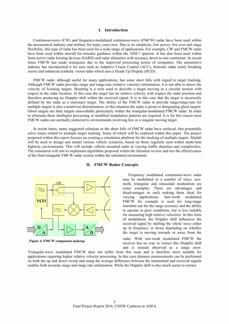
Figure 4. FMCW component makeup

Final Project Report 2016, UNSW Canberra at ADFA
3
A. Basic FMCW Concepts FMCW radar unlike CW radar can detect
Doppler shift as well as range information. This is done by effectively adding a time stamp to the transmitted waveform via frequency modulation; the received waveform may then be mixed with the reference wave within the mixer. The Doppler shift and beat frequency are then extracted and processed for relative velocity and range information respectively. The beat frequency is simply the magnitude of the difference between the reference signal and the received signal frequency, for static targets the difference is proportional to the range-to-target. For moving targets the range extraction is more complicated.
𝑅 = $%∙'
(∙∆$∙$* (1)
Where fb is the beat frequency (Hz) due to the target range, Df is the frequency deviation present within the modulation pattern, and fm is the rate of modulation for the triangular FMCW signal. Although, this formula is only applicable when both slopes of the triangular modulation are equal. When designing a FMCW radar system, range accuracy and resolution must also be considered. Range accuracy refers to conformance between the estimated position and the true position of the platform8, where the range resolution is the ability of the radar to differentiate between two targets that are close together in range. If the range resolution is lower than required, two targets may be seen by the radar as a single target to the user. Range resolution is dictated by the frequency deviation and is analogous to pulse width of a tradition pulse radar10. Similarly, the modulation rate within a FMCW radar is analogous to pulse repetition frequency (PRF) within a pulse radar system and sets the maximum ambiguous range of the system. As with PRF, if the modulation rate is too small for the application, the FMCW radar system may incorrectly identify a target outside the maximum ambiguous range as being closer than its true range.
Figure 4 shows a typical component landscape for a FMCW radar system. Within this makeup one can
identify the mixing of the original signal (f0) and the received signal (f1) which is the Doppler shifted signal (f0+fd). Although the mixer can output both the addition and subtraction on the two signals, we are only interested in the latter10. Equation [2] shows the mathematic explanation of the mixing process.
sin 𝑓/ ∙ sin 𝑓/ + 𝑓1 =12cos 𝑓/ − 𝑓/ + 𝑓1 − cos 𝑓/ + 𝑓/ + 𝑓1
= 7
8cos −𝑓1 − cos 2𝑓/ + 𝑓/ (2)
=12cos 𝑓1 − cos 2𝑓/ + 𝑓/
The resultant frequency is a combination of two components that vary greatly in the order of magnitude, as
f0 is of the gigahertz range where fd is of the kilohertz range. In regards to FMCW radar systems, we are only concerned with the Doppler information and it is for this reason that a bandpass filter is used to attenuate the higher order frequencies. The bandpass filter’s upper and lower cut-off frequencies dictate the maximum and minimum radar processing velocities, respectively. For an automotive radar such as the one simulated within this paper, a minimum processing velocity of approximately 3.6m/s (1km/h) may be adequate. Equation [3] shows how the lower cut-off frequency may be calculated. The process is the same for the upper cut-off frequency using the maximum desired velocity for the radar system.
𝑓1(:;<=>'?@A;$$) =2 ∙ 𝑣> ∙ 𝑓/
𝑐= 2 ∙ 3.6 ∙ 76 ∙ 10J
3 ∙ 10K= 1.824𝑘𝐻𝑧(3)
Figure 5. FMCW radar waveform for a single moving target (a) Transmitted and Received signal, (b) The corresponding beat frequency.

Final Project Report 2016, UNSW Canberra at ADFA
4
B. Tracking Using FMCW In order to track a target the radar system must first identify all potential targets and then assign a tag
(identification number eg. target no.1, 2, 3 etc.) to each target. Data then needs to be processed and stored on for each target. The simulated radar’s ability to track and maintain the correct assignment of the targets will depend on the processing algorithm and the complexity of the environment. The successful elimination of ghost targets is also heavily dependent on the algorithm effectiveness. Although the triangular-wave provides improved range rate information when compared to the saw-tooth wave, it is more susceptible to ghost targets due to replicated frequency deviations on both the upward and downward slope of the frequency modulation wave. This makes it more difficult when attempting to distinguish between multiple targets and requires intelligent processing in order to improve the target tracking success rate. It is for this reason FMCW radar is usually considered for single target tracking such as missile guidance or vehicle speed radar as used by law enforcement. To overcome this issue as discussed within the literature review, there are many proposed methods with varying levels of complexity and reliability.
III. Literature Review 1. FMCW radar As discussed earlier FMCW radar has seen a resurgence of interest in recent times, this is mainly for three
reasons. Firstly, the modulations format is readily compatible with a wide variety of solid-state transmitters8. Secondly, the range information extraction can now be done digitally using the processor based fast Fourier transform (FFT). The final reason is due to the fact that FMCW radars are difficult to detect using conventional forms of intercept systems8. FMCW radar has both linear and sinusoidal modulation methods which have both been used is the past. Linear modulation is more useful for FFT processor operations and for extracting the target range information over a wider range8. Processing of FMCW radar moving target indicator (MTI) operates in an almost identical manner to pulse radars8.
FMCW also enables the radar to have an extremely high time bandwidth product making it highly resistant
to interception from electronic support measure (ESM) systems. This is due to the impracticality of matching the ESM receiver to the radar's sweep pattern8. Another advantage of linear FMCW is the ability for very good range resolution depending on the excursion of the frequency modulation (FM). The range resolution is therefore easily adjustable by simply altering the FM excursion8. Other waveform types have been proposed, such as phase shift keying which offers similar advantages to FMCW. These include the compatibility with solid state transmitters and interception difficulty. The main advantages FMCW has over phase shift keying are complexity, resistance to interference, the ability to implement Sensitivity Time Control (STC) and its compatibility with reflected power cancellers8.
2. Automotive Radar The automotive industry is experiencing an increasing demand for vehicle safety systems. One of the major
tasks of automotive radar safety systems is pedestrian detection4. Although cameras are one of the main sensors used by pedestrian detection systems they become less effective in complex conditions or lighting scenarios. It is in these conditions that FMCW radar based solutions are more advantages4. In order to build a complete and robust pedestrian detection system both methods of detection would need to be considered. Pedestrian detection within the urban driving environment can be a difficult due to the static targets, other vehicles and confusion when pedestrians are in a close proximity to large radar cross section (RCS) targets. In this environment it is expected that the received signal may have a low signal-to-clutter ratio (SCR)4. To combat these issues a 24GHz FMCW radar micro-Doppler analysis system has been proposed enabling classifications of humans, animals and vehicles. This is carried via analysis of kinetic-based spectrographic data in order to classify each target.
Another major component of the automotive radar detection system is autonomous/adaptive cruise control
(ACC) system. In order for the system to function correctly the correct target/vehicle must be differentiable from clutter, where clutter can be considered any object unrelated to the tracked target. Since clutter is due to complex background echoes, clutter modeling is essential and can be quite a challenging task for the radar system7. Although there has been a number of previous empirical studies and modeling of clutter with regard to airborne and static ground targets, there have been few related to FMCW automotive radar clutter7. Development of clutter modeling is underway using data collected from urban environments at varying realistic road speeds. Improved modelling of road clutter will be key to the new age of FMCW radar within the automotive industry.

Final Project Report 2016, UNSW Canberra at ADFA
5
3. Multiple target-tracking In multi-target scenarios, triangular FMCW radar
brings out false/ghost targets due to the frequency modulation waveform shape2. This has the effect of degrading the radars performance or increasing the complexity of the algorithm required for the correct assignment of targets. The complexity is also drastically increased when the number of real targets increases. Ghost targets may also arise through the range-velocity extraction process. This is due to the fact that the targets may have a large difference in
respective ranges or relative velocities. Another potential cause may be that the system incorrectly identifies a combination of beat frequencies as a ghost target2. Figure 2 shows an example of a multi-target situation, the real targets are identified with a red diamond and all others are considered to be ghost targets. A way to improve the correct target assignment of the FMCW radar in a multi-target environment is by altering the triangular frequency modulation waveform. Figure 1 and Figure 3 show examples of two different linear modulation methods which effectively reduce the evidence of ghost targets.
Figure 1 shows a waveform proposed to improve the elimination of ghost targets while maintaining a low complexity required for processing. For the section of the waveform ‘T1’ an approximate range and Doppler shift can be acquired. The second portion
of the modulation ‘T2’ acquires more accurate range and velocity but also acquires associated ghost targets. Combining the information from the two allowed showed an improvement of the miss-detection rate from 67% to 3%2. This can be observed in Figure 2. Another proposed method of linear modulation sees the addition to the traditional triangular waveform. Figure 3 shows the proposed modulation waveform and the addition of a flat frequency period in between the upward and downward slope periods. The flat frequencies are modulated by a PN code sequence
within a specified frequency range. The consequence is unambiguous relative velocities can be extracted from the flat frequency period eliminating potential ghost targets3. The corresponding waveform not only eliminates ghost targets but also provides the advantages of both FSK and FMCW formats3.
IV. Project Details
A. Aims This report aims to successfully simulate the tracking of multiple targets/vehicles within a number of typical
highway scenarios. The radar simulation will base the simulation on previous research papers that propose methods of multiple target tracking. The simulation will also test the limitations of the tracking system through test procedures, which will define the potential applications and possible project improvements/extensions. The project will aim to provide a simulated FMCW tracking radar with potential applications within the automotive industry, UNSW Radar course laboratory program or Australian Regular Army. With this in mind the specification of the radar will also offer a robust, cost effective solution suitable for a vehicle mounted radar.
Figure 1. Two stage triangular modulation pattern
Figure 2. Example of FMCW radar ghost and real targets with triangular modulation FMCW radar
Figure 3. Example of a proposed modulation pattern tracking a single moving target.

Final Project Report 2016, UNSW Canberra at ADFA
6
B. Methodology The frequency modulated continuous-wave radar multiple target tracking simulation has been developed
using systems engineering and software engineering practices. The simulation implements a proposed multi-tracking process using Matlab. The problem has been broken down into distinct sub-problems for simplicity
a) Simulation of FMCW radar (Single target tracking) b) Multiple target tracking
C. Implementation The simulated FMCW radar is constructed using Matlab with specifications based on that seen within the
literature review papers. A sin wave carrier frequency of 76GHz modulated with a 250MHz linear triangular frequency deviation/bandwidth. A system with a range resolution of less than 1m, maximum range of 200m and a maximum transmit power of 4mW has been implemented. The radar tracks multiple vehicles in a highway type scenario with vehicles crossing through the same range at varying speeds. Based on the closing speed of the vehicles crossing range paths the simulation estimates the potential error margin.
1. Simulation of FMCW radar (Single target tracking) Simulation a single target scenario was based on typical closing speeds likely to be encountered when
driving on a highway. The radar parameters are set as per the characteristics stated previously and then assigned a velocity of 100km/h. A single target vehicle must then be defined with a range and range-rate information after which a looped simulation will be carried out. Simulated radar must then output range and range-rate information with a realistic error based on real world factors. This is carried out by extracting the relevant information from the transmitted and received signal comparison or beat frequency. The information is then decimated and compared to the actual target vehicle range and relative speed entered for the simulation. Following the confirmation of this functionality for varying relative range and range-rates, the relevant testing procedure mentioned later within this report was then carried out to test the success of this simulation phase.
2. Multiple target tracking The multiple target-tracking phase of the project initially implements multiple targets with varying range and
range-rate characteristics. This stage does not include crossing range paths as this may be a non-trivial exercise and will be covered in the next phase of the project. The simulation creates multiple scenarios using two or more target objects each with an associated range separation and range-rate. This phase of the simulation also correctly identifies and eliminates ghost targets where applicable. This subsection of the simulation platform allows methods based on the those proposed within the literature review. Once again the error margins will aim to be as close to that expected within real world scenarios. Tracking multiple crossing targets requires additional data processing and storage within the looped scenario. Each acceptable target the radar detected acquires an identification number. From this moment tracking information is processed and stored within a data log. This phase sees multiple target objects traverse a path with range crossing. The simulated radar is required to correctly identify the targets after the range-crossing event is completed. based on the closing velocity between the two targets prior to the range-crossing event. Based on this pre-range crossing information the two targets will acquire an accuracy figure based on the non-unity probability of the tracking prediction correctness. The accuracy figure and final location of each target will be produced and printed for comparison to the actual configured simulation scenario.

Final Project Report 2016, UNSW Canberra at ADFA
7
D. Testing Each project phase has an associated testing procedure to confirm the correct operation, correctness,
robustness and limitations of the simulation platform. The first phase will test a two vehicle scenario including the radar mounted vehicle and one object vehicle with varying closing speeds. The simulated received signal will need to correctly extract the range and range-rate information. The information including error will be decimated and output for a clear comparison to each user selected simulation range and range-rate parameters. The test will be deemed successful if the results with are within the selected simulations parameters inclusive of error.
The second phase will simulate multiple vehicles testing the limitations of the tracking simulation. Parameters such as minimum range resolution will be tested in order to understand where radar range crossing solutions may be required. Initially two vehicles will be tracked with varying closing speeds. After which the limitation of the multiple target tracking will be tested to find the maximum tracking ability of the radar, excluding range crossing events.
The final phase of the project will require the most testing as it involves target range crossing with non-unity probability of correct target assignment. Initially two targets will cross paths with a high velocity differential. After which the closing speeds will be lowered and the success rate tested. The limitations will be tested and where required a solution will be applied to increase the success rate and minimalisation of ghost targets.
V. Results This section will detail the results associated with the FMCW radar tracking simulation testing, verification
and analysis of results. To confirm the success and realism of the simulation multiple simulation variables were altered and the resultant average range and range-rate were recorded. Doing so helped to also understand the simulation behaviour, limitations and processing demand. The goal was to not only produce a platform for potential FMCW radar development and testing but also discover a realistic compromise between accuracy, cost and processing demand. The simulation platform realism also required compromise, as was discovered during the validation stage the MATLAB object-orientated (OO) style also offered certain unrealistic behaviours. As the simulation is also an automotive highway based scenario range-rate/velocity was converted to speed in km/h.
1. Simulation of FMCW Radar (Single target tracking) In order to create a single vehicle target tracking simulation within the Matlab platform, both the radar and
target vehicle objects were created. This allowed each object vehicle’s variables to be managed, updated and reduced algorithm complexity drastically. This allowed the simulation to run faster and created a more realistic FMCW radar. The simulation environment and radar specifications were then created. This included not only the parameters such as carrier frequency, modulation frequency, modulation sweep time, maximum vehicle relative velocity and range but also free space and noise modelling.
The modulation-sweep time was selected and based on the desired maximum range of the vehicles radar system. The sweep time must be much greater than the round time taken for the round trip propagation to the maximum range. This resulted in the radar system sweep time of approximately 7 microseconds, requiring the radar to sweep through 250MHz in a small amount of time. Although this provided for high range accuracy with over 142,000 range position updates per second. The short sweep time required a high amount of processing power, that would likely exceed the cost requirements expected of an automotive industry radar system. It was for this reason a larger sweep time of 2ms was used for testing.
The next consideration for the simulation was the FMCW waveform object and radar specifications. The waveform object and radar specifications based on automotive industry standards9 are summarised in Table [1].
Item Parameter Value Item Parameter Value
1 Operating Frequency 76 GHz 5 Noise Figure 4.5dB 2 Sweep Bandwidth 250Mhz 6 Antenna Aperture 6 x 10⁻⁴m 3 Sweep Time 20ms 7 Antenna Gain 27dB 4 Radar Power 4mW 8 Transmitter Gain 32dB
Table 1. Simulation FMCW waveform object and radar specifications

Final Project Report 2016, UNSW Canberra at ADFA
8
The free space modeling was also carried out using the Matlab object-oriented format. The free space object within the simulation, simulates a narrowband signal propagation and applies a range dependent gain, phase shift and time-delay to the waveform input. Equation [4] shows this relationship.
𝑌 𝑡 = 𝑋(𝑡 − 𝜏)/𝐿 (4)
Where t is the delay and L is the propagation loss. t is simply R/c where R is the propagation distance and c
is the propagation speed. The free space propagation loss (L) is given by Equation [5] 𝐿 = ((WX
Y)8 (5)
The free-space model within the simulation offers a propagation behaviour dependent on the sampling rate
and operating frequency. Using a two-way propagation dynamic modeling a one-dimensional environment for simplicity. As will be discussed later in the Recommendations section the one-dimensional (1D) object-oriented free-space environment offers both advantages and disadvantages when compared to the (X,Y,Z) free-space model. As basic FMCW radar does lacks both azimuth and elevation while offering only range and range-rate information. It was decided the 1D object-oriented simulation style was sufficient for the multiple vehicle highway scenario.
Throughout the design and testing phases, a cost vs accuracy balance was required mainly with regards to
important simulation parameters. The manner in which the simulation processes the range and range-rate information needed to align with an automotive radar. With this in mind the simulation made use of a buffer to store a certain amount of frequency sweeps before extracting the relevant information via a Fast Fourier Transform (FFT). The buffer size plays a large role in deciding how the system will behave with regards to response time, accuracy and processor requirements. This is where a compromise must be taken in order to simulate a system likely to be affordable within the automotive industry. To find a suitable buffer size, system testing was carried out and recorded. Both the range and speed errors for a given buffer size relationship are displayed in Figure [6] and Figure [7].
It can be seen that the larger buffer size improved the accuracy of the range while having less effect on the Doppler shift processing. It is for this reason the range data was the main consideration when selecting a simulation buffer size. A buffer size of 16 was selected for the simulation as it provided a good compromise between accuracy and processing time. A range error of less than 1m provided the accuracy required as well as requiring less processing power for FFT calculations. A better accuracy was achieved with a
Figure 6. Radar range error vs buffer no.
Figure 7. Radar speed error vs buffer no.
0 5 10 15 20 25 30 350
0.5
1
1.5
2
2.5
Range Error (Avg) Quadratic Trendline
0 5 10 15 20 25 30 350
0.1
0.2
0.3
0.4
0.5
0.6
0.7
0.8
0.9
1Speed Error (Avg) Linear trendline

Final Project Report 2016, UNSW Canberra at ADFA
9
buffer size of 32, this unfortunately increased the simulation time exponentially, and would likely exceed the cost benefit balance for an automotive FMCW radar. Once the buffer size was selected the number of buffer iterations combined with a set pause time set the total simulation time of 3 seconds. This allowed adequate time for a number of different scenarios such as vehicle range crossing to be carried out.
Another variable that must be considered when modelling real world behaviour of any radar is noise
modelling. Noise modelling was split into two parts, noise within the FMCW radar system components and noise associated with the propagation through free-space. For simplicity the free-space noise was considered to be negligible. To model the noise within the radar system a noise figure was incorporated in the receiver object and varied to understand the noise impact on the simulated system. Figure [8] and Figure [9] show the relationship between the noise figure, range and range-rate error. It can be seen that a noise figure above 10dB starts to have a significant effect on the accuracy of both range and range-rate within the system. Based on automotive industry standard radar systems the expected noise within the radar system was set to 4.5dB.
2. Multiple target tracking Modeling multiple vehicle/targets the simulation loop was altered to include another vehicle object with
another associated range and range-rate variables. Initially the vehicles were set with range separation and no range crossing. The simulation modelled both vehicles successfully with accuracy and errors falling within the desired performance specifications. The simulation was able to model more vehicles but for the sake of performance testing two target vehicles were adequate.
The second phase of multi-target tracking required range crossing during the simulation time and any error or untoward target interactions to be recorded. The simulation tracked both targets to within 1m with no target confusion recorded. The simulations were then altered with closing speeds reduced to 3km/h will no evidence of reduced tracking performance. This accuracy and lack of target confusion enabled for accurate multiple target tracking results showing little target interaction.
Figure 8. Radar range error vs (noise + reflections) power
Figure 9. Radar speed error vs (noise + reflections) power
10-1 100 101 1020
0.1
0.2
0.3
0.4
0.5
0.6
0.7
Speed Error (Avg) Quadratic trendline
10-1 100 101 1020
0.5
1
1.5
2
2.5
3
Range Error (Avg) Trendline
Final Project Report 2016, UNSW Canberra at ADFA
10
VI. Conclusions This report looked at the FMCW radar basic concepts, applications, weaknesses and proposed a solution to
the short fall for multi-target tracking environments. The simulation is separated into three sub-problems that are; single target, multi-target and multi-target with range crossing simulations. The FMCW radar simulation platform provides a solid basis for which multiple automotive theoretical radar solutions can be behaviorally tested. The modeling of free-space, radar system gain, noise and road reflections provide realistic modeling of real world scenarios with the ability for simple extensions to model multiple environments such as more cluttered or complex environments.
VII. Recommendations To improve on the current FMCW simulation platform, the following recommendations are suggested: I. Incorporation of multiple target interactions or ghost targets (i.e. through non-object orientated
targets), II. Implementation of the waveforms as shown in Figure [1] and Figure [3]. Test both linear
modulation waveforms for the potential elimination of ghost targets within the simulation platform. III. A more realistic modeling environment. This may be carried out by incorporating a non-object
oriented environment such as the (x,y,z) style free-space modeling. The ability for multiple vehicles to interact with regards to the received signal will offer a much more usable and realistic model.
VIII. Acknowledgments I would like to thank my supervisor Dr Neda Aboutorab the guidance and mentoring through the project
process. You are one of the most patient people I know and it has been a pleasure to work with you. Lastly, I would like to thank my partner Rachel for her support not only during this project but for the last four years, I could not have it without you.

Final Project Report 2016, UNSW Canberra at ADFA
11
References 1Kim, D.-B. & Hong, S.-M., n.d. Multiple-target tracking and track management for an FMCW radar network, s.l.: s.n. 2Hyun, E., Oh, W. & Lee, J.-H., n.d. Multi-Target Detection Algorithm for FMCW Radar, Daegu: s.n. 3Fan, Y., Xiang , K., An, J. & Bu, X., n.d. A New Method of multi-target detection for FMCW Automotive Radar, Beijing: Beijing Institute of Technology. 4Villeval, S., Bilik, I. & Gurguz, S. Z., n.d. Application of a 24 GHz FMCW Automotive Radar for Urban Target Classification, s.l.: s.n. 5Chi-Hsien Lin, Y.-S. W. Y.-L. Y. S.-H. W. G.-Y. C.-H. S. a. H.-Y. C., n.d. A 24-GHz Highly Integrated Transceiver in 0.5-µm E/D-PHEMT Process for FMCW Automotive Radar Applications, Jhongli: s.n. Chung, H. H. et al., n.d. A Bandpass Al DDFS-Driven 19GHz Frequency Synthesizer for FMCW Automotive Radar, s.l.: s.n. Falconbridge, I., 2002. Radar Fundamentals, Canberra: Argos Press. Fan, Y., Xiang , K., An, J. & Bu, X., n.d. A New Method of multi-target detection for FMCW Automotive Radar, Beijing: Beijing Institute of Technology. Hyun, E., Oh, W. & Lee, J.-H., n.d. Multi-Target Detection Algorithm for FMCW Radar, Daegu: s.n. Kim, D.-B. & Hong, S.-M., n.d. Multiple-target tracking and track management for an FMCW radar network, s.l.: s.n. Ma, Y.-Z.et al., n.d. Road Clutter Spectrum of BSD FMCW Automotive Radar, s.l.: s.n. Stove, A. G., n.d. Linear FMCW radar techniques, s.l.: s.n. Villeval, S., Bilik, I. & Gurguz, S. Z., n.d. Application of a 24 GHz FMCW Automotive Radar for Urban Target Classification, s.l.: s.n.
Image Credits Figure 1 - Hyun, E., Oh, W. & Lee, J.-H., n.d. Multi-Target Detection Algorithm for FMCW Radar, Daegu: s.n. Figure 2 - 3Fan, Y., Xiang , K., An, J. & Bu, X., n.d. A New Method of multi-target detection for FMCW Automotive Radar, Beijing: Beijing Institute of Technology.
Figure 3 - Fan, Y., Xiang , K., An, J. & Bu, X., n.d. A New Method of multi-target detection for FMCW Automotive Radar, Beijing: Beijing Institute of Technology.
Figure 4 - http://www.st-andrews.ac.uk/~mmwave/mm-waves/avtis/theory-mmw-imaging/radar/
Figure 5 - http://www.radartutorial.eu/02.basics/Frequency%20Modulated%20Wave%20Radar.en.html