multiranger - ddhitech.co.kr i mmmmm table of contents table of contents the multiranger 100 and 200...
TRANSCRIPT

Instruction Manual October 2003
100 / 200multiranger
© Siemens Milltronics Process Instruments Inc. 2003
Safety Guidelines
Warning notices must be observed to ensure personal safety as well as that of others, and toprotect the product and the connected equipment. These warning notices are accompaniedby a clarification of the level of caution to be observed.
Qualified Personnel
This device/system may only be set up and operated in conjunction with this manual.Qualified personnel are only authorized to install and operate this equipment in accordancewith established safety practices and standards.
Warning: This product can only function properly and safely if it is correctly transported,stored, installed, set up, operated, and maintained.
Note: Always use product in accordance with specifications.
Copyright Siemens Milltronics ProcessInstruments Inc. 2003. All Rights Reserved
Disclaimer of Liability
This document is available in bound version and inelectronic version. We encourage users topurchase authorized bound manuals, or to viewelectronic versions as designed and authored bySiemens Milltronics Process Instruments Inc.Siemens Milltronics Process Instruments Inc. willnot be responsible for the contents of partial orwhole reproductions of either bound or electronicversions.
While we have verified the contents ofthis manual for agreement with theinstrumentation described, variationsremain possible. Thus we cannotguarantee full agreement. Thecontents of this manual are regularlyreviewed and corrections are includedin subsequent editions. We welcomeall suggestions for improvement.
Technical data subject to change.
MILLTRONICS®is a registered trademark of Siemens Milltronics Process Instruments Inc.
Contact SMPI Technical Publications at the following address:
Technical PublicationsSiemens Milltronics Process Instruments Inc.1954 Technology Drive, P.O. Box 4225Peterborough, Ontario, Canada, K9J 7B1Email: [email protected]
For the library of SMPI instruction manuals, visit our Web site: www.siemens-milltronics.com

i
mm
mm
m
Table of Contents
Table of Contents
The MultiRanger 100 and 200 ...............................................................................................................1
MultiRanger 100 ............................................................................................................................1MultiRanger 200 ............................................................................................................................1
The Manual ...............................................................................................................................................1Manual Symbols ............................................................................................................................2Configuration Examples ...............................................................................................................2
Specifications ...............................................................................................................................................3
Installation ......................................................................................................................................................8
Mounting ...................................................................................................................................................8Mounting Locations ......................................................................................................................8Mounting Instructions ..................................................................................................................9
Wall Mount ........................................................................................................................... 9Cable routed through a conduit: .................................................................................... 10Panel Mount ....................................................................................................................... 11Mounting the Enclosure .................................................................................................. 12
MultiRanger Board .....................................................................................................................13Installing the Battery ..................................................................................................................13Installing SmartLinx Card ..........................................................................................................14Optional Equipment .....................................................................................................................14
Wiring ..............................................................................................................................................................15
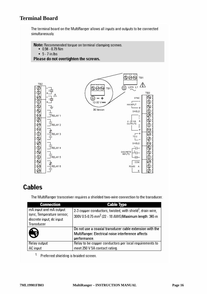
Terminal Board .......................................................................................................................................16Cables .......................................................................................................................................................16Transducers ............................................................................................................................................17Relays .......................................................................................................................................................17Temperature Sensor .............................................................................................................................18mA Input [MR 200 only] .......................................................................................................................18mA Output ...............................................................................................................................................18Level System Synchronization ...........................................................................................................19Power .......................................................................................................................................................19Digital Communications .......................................................................................................................20
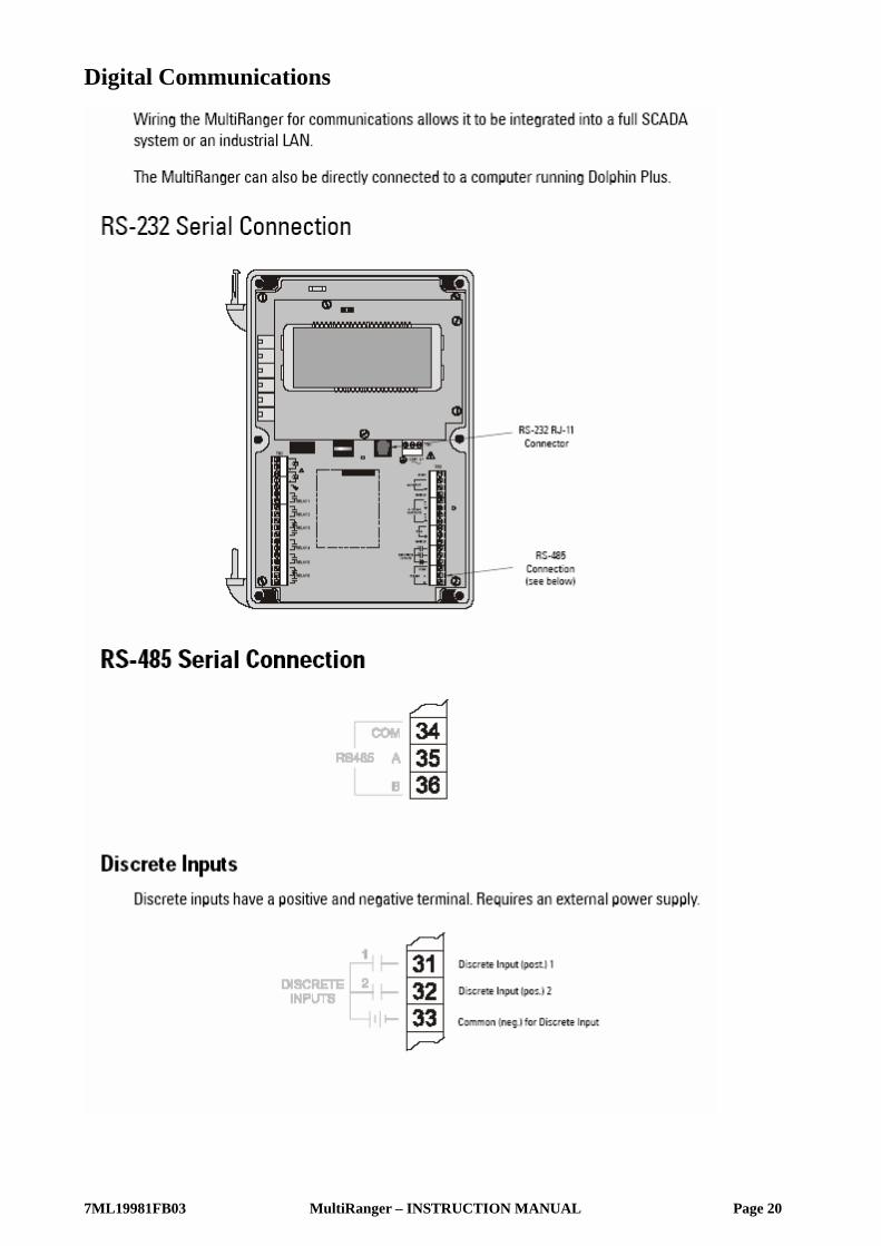
RS-232 Serial Connection ..........................................................................................................20RS-485 Serial Connection ..........................................................................................................20
Discrete Inputs................................................................................................................... 20
Operating the MultiRanger ..................................................................................................................21
RUN Mode ..............................................................................................................................................21Readings in RUN Mode .......................................................................................................................22Status Parameters ................................................................................................................................23Controlling the Display .........................................................................................................................24
Adjusting the primary reading for four-digit LCD readout:...................................... 24Auxiliary Reading ........................................................................................................................24Multiple Readings [MR 200 only] ............................................................................................25
PROGRAM Mode ..................................................................................................................................26

ii
mm
mm
m
Tabl
e of
Con
tent
sStarting PROGRAM Mode ..................................................................................................................26
Hand Programmer .......................................................................................................................26Programmer Keys ........................................................................................................................27
Dolphin Plus ............................................................................................................................................28Dolphin Plus Toolbar Buttons ...................................................................................................29
Activating the MultiRanger .................................................................................................................30Changing Parameters .................................................................................................................30
Security ....................................................................................................................................................31Using Units or Percent (%) ..................................................................................................................31Parameters Types ..................................................................................................................................31Parameter Reset ....................................................................................................................................32Display Readout .....................................................................................................................................32
Changing Parameters(Dolphin Plus) .......................................................................................33Parameter Indexing ....................................................................................................................34
Primary and Secondary Indexes .......................................................................................................35Primary Index ..................................................................................................................... 35Secondary Index................................................................................................................ 35
Starting Measurement ........................................................................................................................36Single Point Models ....................................................................................................................36
Average or Differential [MR 200 only] .......................................................................... 37Dual Point Models .......................................................................................................................37
Average or Differential [MR 200 only] .......................................................................... 38Measurement Conditions ..........................................................................................................38
Response Rate ................................................................................................................... 38Dimensions [MR 200 only]............................................................................................... 38Failsafe................................................................................................................................. 38
Relays ...............................................................................................................................................................39
General Introduction ...................................................................................................................39Relay Function ..............................................................................................................................39
Alarm .................................................................................................................................... 39Pump..................................................................................................................................... 40Miscellaneous.................................................................................................................... 40Relay Status � Non Run Modes .................................................................................... 41
Relay States ..................................................................................................................................41Relay Related Parameters ........................................................................................................41
Relay Wiring Test .............................................................................................................. 42Relay Activation ...........................................................................................................................42Relay Failsafe ...............................................................................................................................43
Preset Applications ...............................................................................................................................44
Backup Level Override ...........................................................................................................................45
Backup Level Override Parameters ..................................................................................................45
Discrete Inputs ...........................................................................................................................................46
Wiring the Discrete Inputs ..................................................................................................................46Programming the Discrete Input Logic ............................................................................................46
mA I/O ..............................................................................................................................................................47
mA Input [MR 200] ................................................................................................................................47

iii
mm
mm
m
Table of Contents
mA Output ...............................................................................................................................................47
Volume [MR 200] ........................................................................................................................................49
Readings ..................................................................................................................................................49Tank Shape and Dimensions ..............................................................................................................49Characterization Chart [MR 200] .......................................................................................................50
Example Chart ..............................................................................................................................50MultiRanger 200 only .................................................................................................................51
Alarms .............................................................................................................................................................52
Level ..........................................................................................................................................................52Setting Simple Level Alarms .....................................................................................................53
Rate [MR 200] .........................................................................................................................................53In Bounds/ Out of Bounds Range [MR 200] ....................................................................................54Cable Fault ..............................................................................................................................................54Temperature [MR 200] ..........................................................................................................................54Loss of Echo (LOE) .................................................................................................................................55
Pump Control ...............................................................................................................................................56
Setting a Pump Down Group ..............................................................................................................56Setting a Pump Up (Reservoir) Group ..............................................................................................57Other Pump Control Algorithms .........................................................................................................59
Set Relays to ALTERNATE DUTY BACKUP [MR 200] ..........................................................59Set Relays to FIXED DUTY ASSIST ........................................................................................59Set Relays to FIXED DUTY BACKUP [MR 200] .....................................................................60Set Relays to ALTERNATE DUTY SERVICE [MR 200] ..........................................................60Set Relays to FIRST IN FIRST OUT (FIFO) ASSIST [MR 200] ............................................61
Optional Pump Controls .......................................................................................................................61Starting Pumps by Rate of Level Change [MR 200] ............................................................61Rotating Pumps by Service Ratio [MR 200] ..........................................................................62Totalizing Pumped Volume [MR 200] ......................................................................................63Setting Independent Failsafe Controls ...................................................................................63Setting a Pump to Run On [MR 200] .......................................................................................64Setting the Pump Start Delays [MR 200] ...............................................................................64Reducing Wall Cling [MR 200] ..................................................................................................64Grouping Pumps [MR 200] ........................................................................................................65Setting a Flush Valve [MR 200] ................................................................................................65Relay Controlled by Communications ....................................................................................66
Tracking Pump Usage ..........................................................................................................................66
Rake (Screen) Control [MR 200] ........................................................................................................67
Setting a Rake Control .........................................................................................................................67Setting the Common Parameters ............................................................................................68Set Relay 1 (Operate Rake) .......................................................................................................68Set Relays 2 to 4 (Level Alarms) ..............................................................................................68
External Totalizers and Flow Samplers [MR 200] ....................................................................69
Relay Contacts .......................................................................................................................................69Totalizer ....................................................................................................................................................69Flow Sampler ..........................................................................................................................................70

iv
mm
mm
m
Tabl
e of
Con
tent
sBased on Volume and Time ......................................................................................................70
Open Channel Monitoring (OCM) [MR 200] ..........................................................................................................................................................71
Common Parameters ............................................................................................................................71Setting Zero Head .......................................................................................................................72
Setting Totalized Volume .....................................................................................................................73Applications Supported by MultiRanger 200 .................................................................................73
BS-3680 / ISO 1438/1 Thin plate V notch weir ............................................................ 73BS-3680 / ISO 4359 Rectangular Flume........................................................................ 74Palmer Bowlus Flume ...................................................................................................... 75H Flume................................................................................................................................ 76
PMDs with Exponential Flow to Head Function ............................................................................77Applicable Weir Profiles ............................................................................................................77Non-Applicable Weir Profiles ..................................................................................................78Parshall Flume ..............................................................................................................................78Leopold Lagco Flume ..................................................................................................................79Cut Throat Flume .........................................................................................................................80
Universal Calculation Support ...........................................................................................................81Typical Flow Characterization ..................................................................................................81Example Flumes ...........................................................................................................................82Example Weirs .............................................................................................................................82
Testing the Configuration ......................................................................................................................83
Simulation ...............................................................................................................................................83Simulating a Single Measurement ...................................................................................................83Simulating a Level Cycle ......................................................................................................................83Checking Volume Characterization [MR 200] .................................................................................84Checking OCM Flow Characterization [MR 200] ...........................................................................84I/O Checkout ...........................................................................................................................................85Application Test .....................................................................................................................................85
MultiRanger Communications ...........................................................................................................87
MultiRanger Communication Systems ............................................................................................87Optional SmartLinx®Cards ................................................................................................................87Communication Systems .....................................................................................................................88Communication Ports ...........................................................................................................................88
Modbus ..........................................................................................................................................88SmartLinx ................................................................................................................................................89Dolphin Plus ............................................................................................................................................89
Communications Installation .............................................................................................................90
Wiring Guidelines ..................................................................................................................................90Ports 1 and 2 .................................................................................................................................90Ports 1 and 2: RS-232 RJ-11 Jack and RS-485 Locations ..................................................90Port 1: RS-232 RJ-11 Jack ..........................................................................................................91Port 2: RS-485 ...............................................................................................................................91
Configuring Communication Ports (Parameters) ...........................................................................92

v
mm
mm
m
Table of Contents
Modbus Register Map ............................................................................................................................95
Word Order (R40,062) ..........................................................................................................................96Map ID (R40,063) ....................................................................................................................................96Product ID (R40,064) ..............................................................................................................................97Point Data (R41,010 � R41,031) ............................................................................................................97Input/Output (R41,070 � R41,143) .........................................................................................................97
Discrete Inputs (R41,070) ..........................................................................................................98Relay Outputs (R41,080) ..............................................................................................................98mA Input (R41,090) [MR 200] .....................................................................................................98mA Output (R41,110-41,111) ........................................................................................................98Pump Control (R41,400 � R41,474) ............................................................................................98Pump ON Setpoint (R41,420 � R41,425) ...................................................................................98Pump OFF Setpoint (R41,430 � R41,435) .................................................................................99Pumped Volume (R41,440 � R41,443) [MR 200] .....................................................................99Pump Hours (R41,450 � R41,461) .............................................................................................99Pump Starts (R41,470 � R41,475) ..............................................................................................99Parameter Access (R43,998 � R46,999) ............................................................................... 100Parameter Indexing ................................................................................................................. 100
Indexing the Parameter Access Area....................................................................... 100Reading Parameters .................................................................................................................101
Global Index Method (P782 = 0) .................................................................................. 101Parameter Specific Index Method (P782 = 1) ......................................................... 102
Writing Parameters .................................................................................................................. 102Global Index Method (P782 = 0) .................................................................................. 102Parameter Specific Index Method (P782 = 1).......................................................... 102
Format Words (R46,000 to R46,999) ............................................................................................... 103Global Index Method (P782 = 0) ............................................................................................ 103Parameter-Specific Index Method (P782 = 1) .................................................................... 103Format Registers ...................................................................................................................... 103
Data Types .................................................................................................................................................. 105
Numeric Values .................................................................................................................................. 105Bit Values .............................................................................................................................................. 105Unsigned Double Precision Integer (UINT32) ............................................................................ 105Split Values .......................................................................................................................................... 106Text Messages .................................................................................................................................... 107Relay Function Codes (P111 Only) ................................................................................................. 108
Error Handling ...........................................................................................................................................110
Modbus Responses ............................................................................................................................110Error Handling ......................................................................................................................................110
Communication Troubleshooting ...................................................................................................112
Generally ...............................................................................................................................................112Specifically ............................................................................................................................................112
Communication Appendix A: Single Parameter Access (SPA) .....................................113
Mapping............................................................................................................................ 113Reading Parameters ...........................................................................................................................113

vi
mm
mm
m
Tabl
e of
Con
tent
sWriting Parameters .............................................................................................................................114Format Register ...................................................................................................................................114Error Codes ...........................................................................................................................................115
Parameter Reference ............................................................................................................................117
MultiRanger 100 and MultiRanger 200 ................................................................................117Helpful Hints ...............................................................................................................................117
Quick Start (P001 to P007) .................................................................................................................119............................................................................................................................................ 119For DPD and DPA Programming [MR 200]............................................................... 120
Volume (P050 to P055) [MR 200] ......................................................................................................123Display and Reading (P060 to P062) ..............................................................................................127Backup Level Override .......................................................................................................................129Failsafe (P070 to P072) ......................................................................................................................131Relays (P100 to P119) .........................................................................................................................132
MultiRanger 200.............................................................................................................. 134Pump Setpoint Modifiers (P121 and P122) [MR 200] ..................................................................139Independent Relay Failsafe (P129) .................................................................................................140Advanced Pump Control Modifiers (P130 to P137) [MR 200] ...................................................141Flush Systems (P170 to P173) [MR 200] .........................................................................................144mA Output (P200 to P219) ..................................................................................................................146Independent mA Setpoints (P210 and P211) .................................................................................148mA Output Limits (P212 and P213) ...................................................................................................149mA Output Trim (P214 to P215) .........................................................................................................150mA Output Failsafe (P219) [MR 200] ...............................................................................................150mA Input (P250 to P260) [MR 200] ...................................................................................................151Discrete Input Functions (P270 to P275) .......................................................................................153Standard Data Logging (P300 to P321) .........................................................................................154Record Temperatures (P300 to P303) ............................................................................................154Record Readings (P304 and P305) .................................................................................................156Pump Records (P310 to P312) ...........................................................................................................156Flow Records (P320 and P321) [MR 200] .......................................................................................157LCD Totalizer (P322 and P323) [MR 200] ........................................................................................158Profile Records (P330 to P337) ........................................................................................................159Auto Record ON and OFF Setpoints (P334 to P337) ....................................................................162Installation Records (P340 to P342) ...............................................................................................164Open Channel Monitoring (P600 to P621) [MR 200] ...................................................................165
Example Exponents........................................................................................................ 167Pumped Volume Totalizer (P622) [MR 200] ...................................................................................174Totalizer (P630 to P645) [MR 200] ....................................................................................................175Range Calibration (P650 to P654) ....................................................................................................178Temperature Compensation (P660 to P664) ..................................................................................181Rate (P700 to P708) ............................................................................................................................183Measurement Verification (P710 to P713) ....................................................................................187Transducer Scanning (P726 to P729) .............................................................................................190Display (P730 to P739) .......................................................................................................................191SmartLinx Reserved (750 to 769) ....................................................................................................194Communications (P770 to P782) .....................................................................................................194SmartLinx Hardware Testing ............................................................................................................197Echo Processing (P800 to P807) ......................................................................................................199

vii
mm
mm
m
Table of Contents
Advanced Echo Processing (P810 to P825) ................................................................................. 202Two methods to select Scope Displays:................................................................... 203
Profile Pointer (P817 to P825) .......................................................................................................... 204Advanced TVT Adjustment (P830 to P835) .................................................................................. 209Advanced Shot Adjustment (P840 to P852) ..................................................................................212Test (P900 to P913) ..............................................................................................................................215Measurement (P920 to P927) ...........................................................................................................219Master Reset (P999) ......................................................................................................................... 222
General Appendix A: Index Types ................................................................................................. 223
Index types ........................................................................................................................................... 223
General Appendix B–Technical Reference ............................................................................. 224
Transmit Pulse ..................................................................................................................................... 224Echo Processing ................................................................................................................................. 224Distance Calculation ......................................................................................................................... 225Sound Velocity .................................................................................................................................... 225Scanning ............................................................................................................................................... 226Volume Calculation [MR 200] .......................................................................................................... 226
Universal, Curved [MR 200] ................................................................................................... 227Flow Calculation ................................................................................................................................. 227
Universal, Linear [MR 200] ..................................................................................................... 228Universal, Curved [MR 200] ................................................................................................... 228
Maximum Process Speed ................................................................................................................ 229
General Appendix C: Troubleshooting ........................................................................................ 230
Common Problems Chart ................................................................................................................. 230Noise Problems ................................................................................................................................... 231
Determine the Noise Source ................................................................................................. 232Non-Transducer Noise Sources ........................................................................................... 232Common Wiring Problems ..................................................................................................... 233Reducing Electrical Noise ...................................................................................................... 233Reducing Acoustical Noise .................................................................................................... 233
Measurement Difficulties ................................................................................................................. 234Flashing LOE Display ............................................................................................................... 234
Adjust Transducer Aiming ........................................................................................... 234Increase Failsafe Timer Value .................................................................................... 235Install a Transducer with a Narrower Beam........................................................... 235Use Dolphin Plus to Debug Echo................................................................................ 235
Fixed Reading ...................................................................................................................................... 235Obstructions in the Sound Beam ......................................................................................... 235Nozzle Mountings .................................................................................................................... 236Set the MultiRanger to Ignore the Bad Echo .................................................................... 236
Wrong Reading ................................................................................................................................... 236Types of Wrong Readings ...................................................................................................... 236Liquid Splashing ........................................................................................................................ 237Adjust the Echo Algorithm ..................................................................................................... 237
Transducer Ringing ............................................................................................................................ 237

viii
mm
mm
m
Tabl
e of
Con
tent
sUnit Repair and Excluded Liability ....................................................................................... 238
General Appendix D: Pump Control Reference ..................................................................... 239
Pump Control Options ....................................................................................................................... 239Pump Groups ............................................................................................................................. 239Pump by Rate [MR 200] .......................................................................................................... 239
Pump Control Algorithms ................................................................................................................. 240Fixed Duty Assist (P111 = 50) ................................................................................................. 240Fixed Duty Backup (P111 = 51) [MR 200] ............................................................................ 241Alternate Duty Assist (P111 = 52) ........................................................................................ 241Alternate Duty Backup (P111 = 53) [MR 200] ..................................................................... 242Service Ratio Duty Assist (P111 = 54) [MR 200] ................................................................ 243Service Ratio Duty Backup (P111 = 55) [MR 200] ............................................................. 244First In First Out (FIFO) (P111 = 56) [MR 200] ...................................................................... 244Pump by Rate (P121) [MR 200] .............................................................................................. 244
Other Pump Controls [MR 200] ....................................................................................................... 244
General Appendix E: Updating Software .................................................................................. 246
Updating Software ............................................................................................................................. 246
General Appendix F: Upgrading ..................................................................................................... 247
Mounting a MultiRanger 100/200 ......................................................................................... 247Connecting the Transducer ................................................................................................... 247
Coaxial Transducer Extention ..................................................................................... 247Connecting a transducer with RG62 coaxial extension cable............................. 248
MultiRanger Plus to MultiRanger 100/200 Parameters .................................................. 249
General Appendix G: Conduit Entry for Class 1, Div 2 Applications ........................... 250
Notes ............................................................................................................................................................. 252

7ML19981FB03 MultiRanger – INSTRUCTION MANUAL Page 1
The MultiRanger 100 and 200
MultiRanger 100과 MultiRanger 200의 두 가지 모델을 적용시킬 수 있는 MultiRanger는 다양한 적용을 할
수 있도록 설계되었다.
• 물, 폐수
• 저장고, 액체측정, Slurries, 고체
• Hoppers, ore bunkers, flotation cells
MultiRanger 100 MultiRanger 100은 single 혹은 dual-point level이며 세 개 혹은 여섯 개의 relay 측정 계기이다. 이는 Digital
Communications를 갖추고 있으며 최근의 echo processing 기술과 진단기능을 제공한다.
MultiRanger 200 MultiRanger 200은 single 혹은 dual-point level이며 세 개 혹은 여섯 개의 relay 계이이며, level과 volume 측
정을 모두 제공한다. 이는 Open Channel Monitoring capabilities와 보다 큰 진보된 pump control algorithms를
갖는다. 그리고 Digital Communications 기능을 갖추고 있다. 또한 최근의 echo processing 기술과 진단기능
을 제공한다.
The Manual 이 매뉴얼은 MultiRanger 100과 MultiRanger 200 모델을 모두 위한 지침을 제공한다. 편의를 위해서
MultiRanger 100의 표준내용을 매뉴얼에 사용하였으며, MultiRanger 200의 추가적인 기능은 marking 하였다.
매뉴얼은 MultiRanger의 모든 정보를 줄 수 있도록 고안 되었으며 제공하는 정보는 다음과 같다.
• Unit을 program하는 방법 • Outline diagrams
• Applications의 예 • Wiring diagrams
• Operation의 원리 • Installation requirements
• Parameter의 값 • Modbus register mapping
• Parameter의 사용 • Modem Configuration
이 매뉴얼에 있어서 질문사항, 코멘트 혹은 제안이 있으시다면 [email protected]의 주소로
연락을 주시기 바랍니다.
Siemens Milltronics의 library를 위해서는 www.siemens-milltronics.com으로 접속하시기 바랍니다.

7ML19981FB03 MultiRanger – INSTRUCTION MANUAL Page 2
Manual Symbols 이들의 사용을 주의 깊게 보기 바람.
Configuration Examples 이 매뉴얼에서 보여지는 configuration 예시는 MultiRanger의 다양함을 보여준다. Application에 접근하는 방
법의 허용되는 범위가 있기 때문에 다른 configuration도 적용이 가능할 것이다.
모든 예시에 있어서 필요로 하는 application을 자세히 알 수 있다. 예시에 필요로 하는 application이 없다
면 가능한 Options을 확인하기 위해서 적용 가능한 parameter reference를 체크하기 바란다.
보다 자세한 정보를 원한다면, Siemens Milltronics 관계자에게 연락을 하기 바람.
www.siemens-milltronics.com

7ML19981FB03 MultiRanger – INSTRUCTION MANUAL Page 3
Specifications

7ML19981FB03 MultiRanger – INSTRUCTION MANUAL Page 4

7ML19981FB03 MultiRanger – INSTRUCTION MANUAL Page 5

7ML19981FB03 MultiRanger – INSTRUCTION MANUAL Page 6

7ML19981FB03 MultiRanger – INSTRUCTION MANUAL Page 7

7ML19981FB03 MultiRanger – INSTRUCTION MANUAL Page 8
Installation Note : • 설치는 유자격자가 행해야 하며, 지방정부의 규정에 맞아야 한다.
• 이 제품은 전기적인 쇼크에 쉽게 영향을 받는다. 알맞은 접지 절차를 따르기 바란다.
모든 field wiring은 적어도 250V에 알맞게 절연되어야만 한다.
Operation 동안에는 Transducer terminal 상에 위험한 voltage가 존재한다.
DC terminals은 IEC 1010-1 Annex H에 따라서 SELV source로부터 제공되어야 한다.
• Non-metalllic enclosure는 도관 연결 사이에서 접지를 제공하지 않는다. 접지형 type bushings와 jumpers를
사용한다.
Mounting
Mounting Locations
Recommended • 주변의 온도는 항상 -20에서 50℃ 이내이어야 한다.
• 대부분의 상호작용이 SCADA system을 통하지 않는다면 MultiRanger display window는 shoulder level에 있
다.
• Hand Programmer를 위한 쉬운 접근이 제공되어야 한다.
• 필요로 하는 Cable의 길이는 최소이어야 한다.
• Mounting surface는 진동이 없어야 한다.
• Unit lid가 open되기 위한 것과 간편한 접근을 위한 충분한 공간이 있어야 한다.
• Laptop computer를 공간은 현장의 Dolphin Plus configuration을 위해서 제공되어야 한다.
Avoid • 햇볕에 직접적으로 노출되는 곳. (직접적인 햇볕을 피하기 위해서는 sun shield를 제공한다.)
• 높은 전압/전류가 존재하는 근처, SCR 혹은 variable frequency motor speed controllers에 접촉하고 있는 곳
7ML19981FB03 MultiRanger – INSTRUCTION MANUAL Page 9
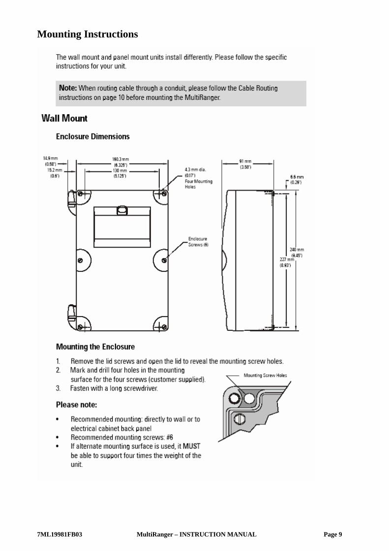
Mounting Instructions
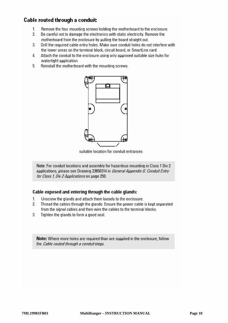
7ML19981FB03 MultiRanger – INSTRUCTION MANUAL Page 10

7ML19981FB03 MultiRanger – INSTRUCTION MANUAL Page 11

7ML19981FB03 MultiRanger – INSTRUCTION MANUAL Page 12
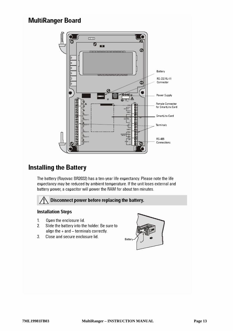
7ML19981FB03 MultiRanger – INSTRUCTION MANUAL Page 13

7ML19981FB03 MultiRanger – INSTRUCTION MANUAL Page 14

7ML19981FB03 MultiRanger – INSTRUCTION MANUAL Page 15
Wiring
7ML19981FB03 MultiRanger – INSTRUCTION MANUAL Page 16
Terminal Board

7ML19981FB03 MultiRanger – INSTRUCTION MANUAL Page 17

7ML19981FB03 MultiRanger – INSTRUCTION MANUAL Page 18

7ML19981FB03 MultiRanger – INSTRUCTION MANUAL Page 19
Level System Synchronization
7ML19981FB03 MultiRanger – INSTRUCTION MANUAL Page 20
Digital Communications

7ML19981FB03 MultiRanger – INSTRUCTION MANUAL Page 21
Operating the MultiRanger

7ML19981FB03 MultiRanger – INSTRUCTION MANUAL Page 22
Readings in Run Mode
Key Function P#
Percent와 Units 사이에서 판독 값을 고정시킨다. • Level : 0-100% • Space or Distance : 100%-0 P920
Numbered pump를 위한 누적된 pump running hours P310
Numbered pump를 위한 누적된 pump starts의 수를 나타내기 위해서 5초 동안 number key를 유지한다. P311
Eight-digit totalizer는 index와 reading area를 사용하는데 고정시키기 위해서 다시 누른다. P737은 default를 세팅한다. OCM과 Pumped Volume에 사용된다.
P322 P323 P920
Head 측정 P926
Head (OCM)에 근거한 순간적인 Flow P925
mA Output 값 P203
온도 P664
Level 변화의 비율 P707
Failsafe Time Left (in%). 판독 값이 업데이트되면 이 값은 (Auxiliary Reading) 100으로 reset되며 다음의 유효한 측정치가 만들어질 때까지 감소하기 시작한다. Failsafe Time Left가 0에 이른다면, LOE가 Display에 나타나게 된다.
Echo Confidence를 나타내기 위해서 4초간 유지한다. P805
Transducer에 의해 global되고 indexed된 입력된 parameter의 값을 나타낸다.
Auxiliary reading은 P731에 규정된 parameter를 나타낸다. P731
Distance P923

7ML19981FB03 MultiRanger – INSTRUCTION MANUAL Page 23
Status Parameters

7ML19981FB03 MultiRanger – INSTRUCTION MANUAL Page 24
Controlling the Display

7ML19981FB03 MultiRanger – INSTRUCTION MANUAL Page 25

7ML19981FB03 MultiRanger – INSTRUCTION MANUAL Page 26
PROGRAM Mode MultiRanger는 이의 특정한 application을 맞추기 위해서 parameter의 세팅에 의해서 프로그램 된다. 거의
대부분의 parameter는 indexed 되고, parameter가 특정한 상태 그리고 한 개의 input 혹은 output 이상에
parameter가 세팅되는 것을 가능하게 한다. MultiRanger가 PROGRAM mode일 때, 이 parameter의 값을 변
경할 수 있으며 operating conditions를 세팅할 수 있다.
Full listing과 parameter 값의 설명을 참고하기 위해서 Parameter Reference 부분을 참고하기 바란다.
MultiRanger의 주요한 programming은 hand programmer에 의해서 행해진다. 다른 접근은 Dolphin Plus
software (개별적으로 구입해야 하는)를 통해서 적용이 가능하다.
Notes : • Run mode로부터 PROGRAM을 활성화하려면, PROGRAM 버튼을 누르고, DISPLAY 를 누른다.
• 측정치가 확인되는 동안에 Display는 간결하게 - - - - 를 읽는다. 읽혀지는 레벨과 다른 Data는 나타나게
되며 프로그램 된 relays들은 작동된다.
• 정상적인 작동에서 Program mode에서의 프로그램 된 unit은 모든 control relay output을 비활성화시킨다.
이의 programming동안은 MultiRanger가 지나쳐짐을 확인한다.
Starting PROGRAM Mode
Hand Programmer Hand Programmer는 MultiRanger에 직접 접근을 가능하게 한다.
Hand Programmer를 맞추고 Program key를 누른다.
Notes : • Programmer에서의 배터리는 교환되지 않는다.
• Hand Programmer는 Siemens Milltronics와는 별개로 주문된다.
편의상 Programmer는 뒤쪽에 magnetic mounting strip을 가지고 있다.
접근이 쉬운 근처에 Programmer를 유지한다.
Display의 위 IR port에 Programmer를 위치한다.
다른 사항이 표시되지 않았다면, 각각의 유효한 키의
누름은 LCD 상에서 변화를 생성한다. Unit의 프로그램 시
확인한다.

7ML19981FB03 MultiRanger – INSTRUCTION MANUAL Page 27
Programmer Keys

7ML19981FB03 MultiRanger – INSTRUCTION MANUAL Page 28
Dolphin Plus

7ML19981FB03 MultiRanger – INSTRUCTION MANUAL Page 29
Dolphin Plus Toolbar Buttons

7ML19981FB03 MultiRanger – INSTRUCTION MANUAL Page 30
Activating the MultiRanger 다음 절차에 있어 모든 지침은 hand programmer에 적용이 되며 MultiRanger가 활성화되게 한다.
1. MultiRanger에 전원을 가한다.
2. Unit 상에서 Programmer를 가리키고 PROGRAM 버튼을 누른다.
3. DISPLAY 버튼을 누른다.
Note : Power up display • Single Point Model
• Transducer의 표면에서 material까지의 거리를 preset 한다.
• Transducer의 선택은 XPS-10을 위해서 preset 한다.
• Empty distance는 5m로 preset 한다.
• Dual Point Model
• Off 상태에서 start되며 레벨 측정치를 갖지 않는다.
• 측정을 세팅하려면, quick start parameter가 조정되어져야 한다.
• 페이지 119의 Quick Start Parameter를 참고바람.
Changing Parameters Note : Parameter 값의 수정이 승인되지 않는다면, Lock parameter (P000)로 접근하여 security code를 입력.
1. Run mode에서 시작하고 Unit을 Program mode로 넣기 위해서 PROGRAM을 누르고 DISPLAY를 누른다.
2. Parameter Number field를 선택하기 위해서 Display를 누른다.
3. Parameter Number를 누른다. 세 번째 digit이 입력된 이후에 parameter 값이 보여진다.
4. 새로운 값을 입력하고 ENTER를 누른다. MultiRanger는 값을 받아들이거나 유효한 값으로 바꿔서 이를
해석한다.
Helpful Hints • Parameter P001에서 P009에서 single digit을 누르고 그 후에 parameter를 나타내기 위해서 DISPLAY를 누
른다.
• ? 아이콘은 MultiRanger가 값을 받아들였지만 입력된 다른 값과 충돌을 일으켰음을 가리킨다.
• Default 값에서 SCROLL arrows는 Quick Start parameter와 바뀌어진 어떠한 것을 보여준다.
• P733은 모든 parameter를 scroll로 접근이 되도록 세팅한다.

7ML19981FB03 MultiRanger � INSTRUCTION MANUAL Page 31
mm
mm
m
Operation
SecurityThe Lock parameter P000 secures the MultiRanger against parameter changes. The unit can still be put into PROGRAM mode when locked, and parameter values can be viewed, but no parameter values can be changed.
When P000 is set to 1954, programming is enabled. To disable programming, enter another value.
P000 (1954) is a fixed value password. Therefore, you should use other means to secure the MultiRanger if security is a concern.
Simulation
P000 Lock also controls how simulations affect control relays. By default, control relays are unaffected by simulation levels. But if P000 is set to �1, they react to the simulated level. See Parameters P925�P927 on page 221 for running a simulation.
Using Units or Percent (%)Many parameters can be viewed either in measurement units (P005) or as a percentage. View the parameter and then press MODE to toggle between units and percentage. The LCD shows the selected measurement type, either units (m, ft) or percentage (%).
MR 200 only:
Percentage is also available when showing flow and volume with 100%, based on the parameter that defines the maximum.
Parameters TypesView Only Parameters
Parameter values indicating status only. They cannot be altered.
Global Values
Parameter values common to all inputs and outputs on the MultiRanger.
When a global parameter is accessed, the index display automatically disappears. When a non-global parameter is accessed, the index display reappears showing the last index number.
Measurement MaximumVolume P051Flow P604

Page 32 MultiRanger � INSTRUCTION MANUAL 7ML19981FB03
mm
mm
m
Ope
ratio
nDefault Values
Parameter default values are indicated with an * in the parameter tables.
P000 Lock
The asterix identifies 1954 as the default value.
Parameter ResetReturning a parameter to factory default.
1. Display the appropriate parameter number.2. Display the appropriate index value (if required).3. Press CLEAR .
4. Press ENTER .
Master Reset (P999)
Returns all parameters to original values.
Use Conditions:
� before initial system installation� following a software upgrade
If complete reprogramming is required, use Dolphin Plus to store and retrieve parameters.
When the dual point option is enabled, P999 is indexed by transducer. Use index 00 to reset the entire MultiRanger.
Display ReadoutThe following readouts are shown when the MultiRanger cannot display a number.
Primary Index Global
Value1954 * OFF: programming permitted
-1 Simulation Controls (relays energize based on simulated level)
other ON: Lock activated and programming not permitted
Display DefinitionParameter has not been set
All values not same when viewing index 0
Value too large for four-digit display
7ML19981FB03 MultiRanger � INSTRUCTION MANUAL Page 33
mm
mm
m
Operation
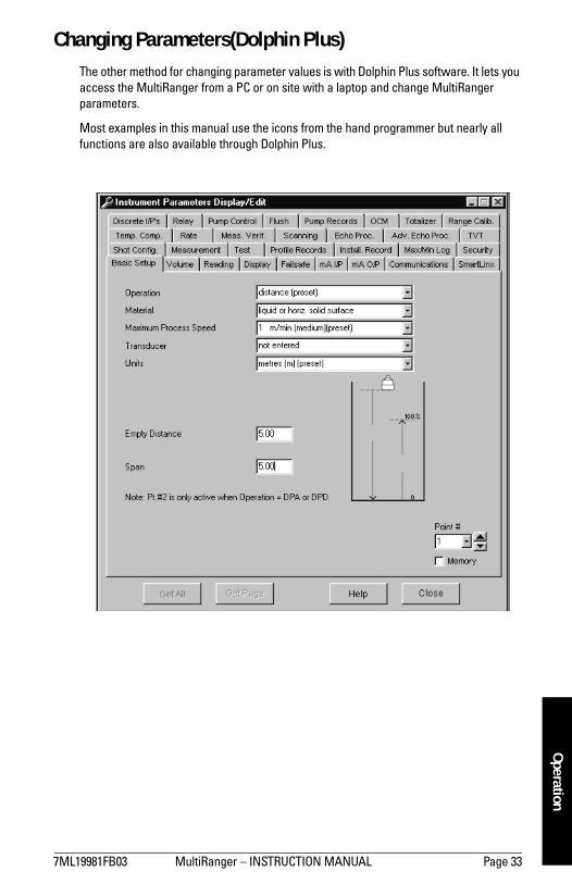
Changing Parameters(Dolphin Plus)The other method for changing parameter values is with Dolphin Plus software. It lets you access the MultiRanger from a PC or on site with a laptop and change MultiRanger parameters.
Most examples in this manual use the icons from the hand programmer but nearly all functions are also available through Dolphin Plus.

Page 34 MultiRanger � INSTRUCTION MANUAL 7ML19981FB03
mm
mm
m
Ope
ratio
n
Parameter IndexingParameters are indexed when they apply to more than one input or output. The index value defines the input/output for that parameter. Indexed parameters contain a value for each index, even if that index is not used.
MultiRanger Display
The index number and the index values are displayed above the parameter indicator on the LCD.
Accessing a Parameter Index
1. Press DISPLAY once to clear current parameter field.2. Enter the new parameter number.
3. Press DISPLAY twice. 4. Press the number of the required index. Or press ARROW keys to scroll
through the available values.
1 2 3 4 65
Index ValueIndex Number
Notes� Transducers are always indexed when the dual point option is enabled.� An indexed transducer is commonly referred to as a Point (short for �Measurement
Point�). Point Number refers to indexed transducers.� To set all indexed values for a parameter to the same value, use index 0.
� MR 200 only: Transducer parameters are indexed only if Operation (P001) is set to Difference (value=4) or Average (value=5) on a single point MultiRanger.
Note: For optimum performance, set values accurately for indexed parameters. Ensure that the correct index value is being changed for each parameter value.

7ML19981FB03 MultiRanger � INSTRUCTION MANUAL Page 35
mm
mm
m
Operation
Primary and Secondary IndexesPrimary Index: relates to direct input or output and can refer to relays, communications ports, and other parameters. In parameters that allow secondary indexes, the primary index is often referred to as a point.
Secondary Index: relates to previously indexed parameters where the parameter requires a second index, permitting multiple values on an indexed input or output.
Primary IndexExample Setting: P111[3] = 52
� P111 sets the Relay Control Function� P111(3) = 52 sets Relay #3 to a value of 52.
Secondary IndexParameters with a secondary index permit multiple values for a primary index (point). For example, a volume calculation based on vessel characterization breakpoints requires a distinct set of breakpoints for each measured point.
Thus the primary index refers to the measurement point, and each secondary index refers to a characterization breakpoint value.
Accessing a Secondary Index
1. Press MODE and then press DISPLAY to activate secondary index. The icon appears under the index field.
2. Enter the secondary index, and then enter the values to set the secondary index.
P111
3 4 5 621
52

Page 36 MultiRanger � INSTRUCTION MANUAL 7ML19981FB03
mm
mm
m
Ope
ratio
nExample [MR 200 only]
P054 provides up to 32 breakpoint levels used with P055 (Volume Breakpoint) for universal volume calculation. The illustration indicates how you can set secondary indexes to specific functions.
� P054 [1,1] = .75m sets breakpoint 1 on transducer 1 to .75m.� P054 [2.1] = 8m sets breakpoint 1 on transducer 2 to 2.75m.
Starting MeasurementThe MultiRanger startup varies between single and dual point models.
Single Point ModelsThe MultiRanger starts in DISTANCE mode with the transducer preset for the XPS-10 and an empty distance of 5 meters. Change the following parameters to reflect your application parameters.
A B CP054 [1.6] = 2m P054 [1,3] = 1.5m P054 [1,1] = .75mP054 [2.6] = 8m P054 [2.3] = 5.5m P054 [2.1] = 2.75m
Parameter Index Value DescriptionP001 G 1 Operation = levelP002 G 1 Material = liquidP003 G 2 Maximum Process Speed = mediumP004 G 104 Transducer = XPS-15P005 G 1 Units = metersP006 G 12 Empty = 12mP007 G 10 Span = 10m
A
C
B
1 2
P054
[6 = 2m]
[3 = 1.5m]
[1 = 0.75m][1 = 2.75m]
[3 = 5.5m]
[6 = 8m]
A
B
C
7ML19981FB03 MultiRanger � INSTRUCTION MANUAL Page 37
mm
mm
m
Operation
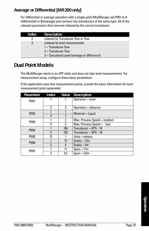
Average or Differential [MR 200 only]For differential or average operation with a single-point MultiRanger, set P001 to 4 (differential) or 5 (average) and connect two transducers of the same type. All of the relevant parameters then become indexed by the correct transducer:
Dual Point ModelsThe MultiRanger starts in an OFF state and does not take level measurements. For measurement setup, configure these basic parameters:
If the application uses two measurement points, provide the basic information for each measurement point separately:
Index Description2 indexed by Transducer One or Two3 indexed by level measurement
1 = Transducer One2 = Transducer Two3 = Calculated Level (average or difference)
Parameter Index Value Description
P001 1 1 Operation = level
2 3 Operation = distance
P002 1 1 Material = Liquid2 1
P003 1 2 Max. Process Speed = medium2 3 Max. Process Speed = fast
P004 1 104 Transducer = XPS - 152 102 Transducer = XPS - 10
P005 G 1 Units = meters
P006 1 12 Empty = 12m2 4 Empty = 4m
P007 1 11 Span = 11m2 3.5 Span = 3.5m

Page 38 MultiRanger � INSTRUCTION MANUAL 7ML19981FB03
mm
mm
m
Ope
ratio
n
3
Average or Differential [MR 200 only]For differential or average operation dual-point MultiRanger, set P001 to 4 (differential) or 5 (average) and connect two transducers of the same type.
All the relevant parameters are then indexed by the correct number:
Measurement ConditionsThe following information will help you configure your MultiRanger for optimal performance and reliability.
Response RateThe response rate of the device influences the measurement reliability. Use the slowest rate possible with the application requirements.
The response rate is also important to functions connected to the filling or emptying indicators.
Dimensions [MR 200 only]The dimensions of the vessel, wet well, or reservoir (except empty and span) are only important if you require volume.
Volume is required to report the level value in terms of volume. The pumped volume function can also report pumped volume or pump efficiencies.
FailsafeThe failsafe parameters ensure that the devices controlled by the MultiRanger default to an appropriate state when a valid level reading is not available.
� P070 � Failsafe Timer activates if an error condition is detected. Upon expiration of the timer, relay status defaults to values based on P071.
� P071 � Failsafe Material Level determines the level reading if the Failsafe Timer expires and the unit is still in an error condition.
� P129 � Relay Failsafe controls the reaction of each relay. See Relay Failsafe on page 43 for more information.
If Failsafe Operation activates frequently, see the Troubleshooting Appendix on page 230.
Index Description2 indexed by Transducer One or Two3 indexed by level measurement
1 = Transducer One2 = Transducer Two3 = Calculated Level (average or difference)
Relay Number
Ring indicates relay is configured
Dot indicates relay is energized/de-energized

7ML19981FB03 MultiRanger � INSTRUCTION MANUAL Page 39
mm
mm
m
Relays
Relays
Relays are the primary controls of external devices such as pumps or alarms.
The MultiRanger comes with extensive control and alarm functions.
General Introduction Six onboard multi-purpose relays are provided on the MultiRanger. Each relay may be independently assigned to one function and has a corresponding status icon on the LCD.
The relay functions fall under three modes of operation:
Relay Function
Alarm
Level
In high alarm, the function goes on when the level rises to the ON setpoint and goes off when the level lowers to the OFF setpoint. In low alarm, the function goes on when the level lowers to the ON setpoint and goes off when the level rises to the OFF setpoint.
In Bounds [MR 200]
The relay will be in alarm if the level is inside the zone between the setpoints.
Out of Bounds [MR 200]
The relay will be in alarm if the level is outside the zone between the setpoints.
Rate of Change [MR 200]
In filling alarm, the function goes on when the rate of filling increases to the ON setpoint and goes off when the rate of filling drops to the OFF setpoint. In emptying alarm, the function goes on when the rate of emptying increases to the ON setpoint and goes OFF when the rate of emptying drops to the OFF setpoint. For emptying alarm, the setpoints must be entered as negative values.
Mode Functionalarm alarm ON = LCD Icon ON = relay coil de-energized pump pump ON = LCD Icon ON = relay coil energizedmiscellaneous contact closed = LCD Icon ON = relay coil energized

Page 40 MultiRanger � INSTRUCTION MANUAL 7ML19981FB03
mm
mm
m
Rela
ysTemperature [MR 200]
In high alarm, the function goes on when the temperature rises to the ON setpoint and goes off when the temperature lowers to the OFF setpoint. In low alarm, the function goes on when the temperature lowers to the ON setpoint and goes off when the temperature rises to the OFF setpoint.
Loss of Echo
The function goes on when the fail-safe timer expires. The function goes OFF when a valid echo is received (fail-safe timer is reset).
Pump
Level
In pump down, the function goes on when the level rises to the ON setpoint and goes off when the level lowers to the OFF setpoint. In pump up, the function goes on when the level lowers to the ON setpoint and goes off when the level rises to the OFF setpoint.
Miscellaneous
Totalizer and Samplers [MR 200]
Refer to Totalizing Pumped Volume on page 63. Relays are normally de-energized, contact closure is approximately 200 mSec duration.
Setpoint - ON / OFF
If the ON setpoint is higher than the OFF setpoint, the relay operates as:
� high alarm � pump down control
If the ON setpoint is lower than the OFF setpoint, the relay operates as:
� low alarm � pump up control
The ON and OFF setpoints can not be the same on an individual relay but may be common to other relays. The dead band or hysteresis is the difference between the ON and OFF setpoints. For in and out of bounds level alarms, the hysteresis is set at ± 2 % of span from either boundary.
7ML19981FB03 MultiRanger � INSTRUCTION MANUAL Page 41
mm
mm
m
Relays
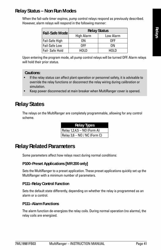
Relay Status – Non Run Modes When the fail-safe timer expires, pump control relays respond as previously described. However, alarm relays will respond in the following manner:
Upon entering the program mode, all pump control relays will be turned OFF. Alarm relays will hold their prior status.
Relay StatesThe relays on the MultiRanger are completely programmable, allowing for any control scheme.
Relay Related ParametersSome parameters affect how relays react during normal conditions:
P100–Preset Applications [MR 200 only]
Sets the MultiRanger to a preset application. These preset applications quickly set up the MultiRanger with a minimum number of parameters.
P111–Relay Control Function
Sets the default state differently, depending on whether the relay is programmed as an alarm or a control.
P111–Alarm Functions
The alarm function de-energizes the relay coils. During normal operation (no alarms), the relay coils are energized.
Fail-Safe Mode Relay StatusHigh Alarm Low Alarm
Fail-Safe High ON OFFFail-Safe Low OFF ONFail- Safe Hold HOLD HOLD
Relay TypesRelay 1,2,4,5 � NO (Form A)Relay 3,6 � NO / NC (Form C)
Cautions:� If the relay status can affect plant operation or personnel safety, it is advisable to
override the relay functions or disconnect the relay wiring during calibration or simulation.
� Keep power disconnected at main breaker when MultiRanger cover is opened.

Page 42 MultiRanger � INSTRUCTION MANUAL 7ML19981FB03
mm
mm
m
Rela
ysP111–Control Functions
The control function energizes the relay coils. When the instrument is at rest (no controls operating) the relay coils are de- energized.
P112–Relay ON Setpoint
Sets the process point at which the relay is tripped.
P113–Relay OFF Setpoint
Sets the process point at which the relay is reset.
P118–Relay Output Logic
Affects relay reaction. Reverses the logic (normally-open to normally-closed or vice versa).
P129–Relay Failsafe
Changes how individual relays react to a failsafe condition on the instrument.
Relay Wiring Test
P119–Relay Logic Test
Checks the application wiring by forcing a relay control function, such as a level alarm or pump control setpoint. Ensure all the relay programming and wiring works properly.
Please verify that ON and OFF respond correctly. Use P119 as a final test once all of the relay programming is done.
Relay ActivationThe flexibility of the relay functions ensures that the MultiRanger can support relay wiring for different systems and applications. Use the following as a guide to the most common parameters.
Relay Setpoints and Functionality
[MR 100]: When a setpoint is reached, the corresponding action is taken. The setpoint can be an ON or OFF setpoint related to a process variable.
[MR 200]: The setpoint can be an ON or OFF setpoint related to a process variable, or a timed setpoint based on interval and duration.

7ML19981FB03 MultiRanger � INSTRUCTION MANUAL Page 43
mm
mm
m
Relays
[MR 100]: Functions affected by setpoint are configured by parameters that determine the application requirements such as timing. P111 Pump and Control functions (see page 134) sets the functions requirements.
[MR 200]: Functions affected by setpoint are configured by parameters that determine the application requirements such as timing. P111 Pump and Control functions (see page 134 sets the function requirements. Other function parameters:
� P132�Pump Start Delay� P133�Pump Power Resumption Delay� P645�Relay Duration
Relay Logic is Modified
Normal operating conditions means that alarms are off and pumps are on. This can be reversed using P118�Relay Output Logic.
Relay Failsafe
P129–Relay Failsafe
Adjusts how individual relays react to a failsafe condition. Relays can be set to:
� OFF Control is by P071�Failsafe Material Level� HOLd Keeps the relay in the current state� dE De-energizes the relay (default for pump controls)� En Energizes the relay

Page 44 MultiRanger � INSTRUCTION MANUAL 7ML19981FB03
mm
mm
m
Rela
ys
Preset ApplicationsPreset applications set up the relay parameters to predetermined values shown below:
Value # Parameters AffectedOff 0 All relays set to OFF
Wet Well 1
1
Pump down with the following settings:
Parameter Relay #1 2 3 4 5 6
P111 52 52 1(H) 1(L) 0 0P112 70% 80% 90% 10% � �P113 20% 20% 85% 15% � �
Wet Well 2
2
Pump down with the following level and rate settings:
Parameter Relay #1 2 3 4 5 6
P111 52 52 1(H) 1(L) 0 0P112 70% 80% 90% 10% � �P113 20% 20% 85% 15% � �P121 1
Because the pumps are started by rate, you must change P703 to desired empty rate.
Reservoir 1
3
Pump up with the following level settings:
Parameter Relay #1 2 3 4 5 6
P111 52 52 1(H) 1(L) 0 0P112 30% 20% 90% 10% � �P113 80% 80% 85% 15% � �
Reservoir 2
4
Pump up with the following level and rate settings:
Parameter Relay #1 2 3 4 5 6
P111 52 52 1(H) 1(L) 0 0P112 20% 20% 90% 10% � �P113 80% 80% 85% 15% � �P121 1
Because the pumps are started by rate you must change P702 to desired fill rate.
Screen
5
Differential control of a screen or rake:
Parameter Relay #1 2 3 4 5 6
P110 3 1 2 3 0 0P111 50 1(H) 1(L) 1(H) � �P112 80% 90% 10% 90% � �P113 20% 85% 15% 10% � �
Alarms
6
General alarms at four setpoints:
Parameter Relay #1 2 3 4 5 6
P111 1(H) 1(L) 1(HH) 1(LL) 0 0P112 80% 20% 90% 10% � �P113 75% 25% 85% 15% � �
7ML19981FB03 MultiRanger � INSTRUCTION MANUAL Page 45
mm
mm
m
Backup Level Override
Backup Level Override
Backup level override provides the option of overriding the ultrasonic input with another contacting point level device, for example, the Pointek CLS 200. The ultrasonic reading is fixed at the programmed switch level until the discrete input is released and the ultrasonic device makes its decisions based on the override value.
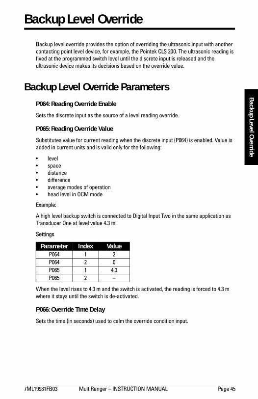
Backup Level Override Parameters P064: Reading Override Enable
Sets the discrete input as the source of a level reading override.
P065: Reading Override Value
Substitutes value for current reading when the discrete input (P064) is enabled. Value is added in current units and is valid only for the following:
� level� space� distance� difference� average modes of operation� head level in OCM mode
Example:
A high level backup switch is connected to Digital Input Two in the same application as Transducer One at level value 4.3 m.
Settings
When the level rises to 4.3 m and the switch is activated, the reading is forced to 4.3 mwhere it stays until the switch is de-activated.
P066: Override Time Delay
Sets the time (in seconds) used to calm the override condition input.
Parameter Index ValueP064 1 2P064 2 0P065 1 4.3P065 2 �
Page 46 MultiRanger � INSTRUCTION MANUAL 7ML19981FB03
mm
mm
m
Dis
cret
e In
puts
Discrete Inputs
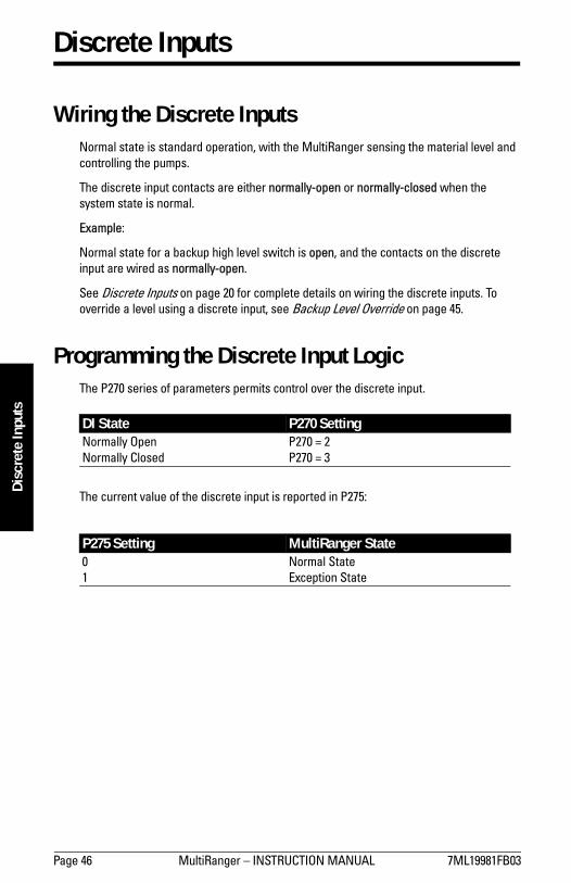
Wiring the Discrete InputsNormal state is standard operation, with the MultiRanger sensing the material level and controlling the pumps.
The discrete input contacts are either normally-open or normally-closed when the system state is normal.
Example:
Normal state for a backup high level switch is open, and the contacts on the discrete input are wired as normally-open.
See Discrete Inputs on page 20 for complete details on wiring the discrete inputs. To override a level using a discrete input, see Backup Level Override on page 45.
Programming the Discrete Input LogicThe P270 series of parameters permits control over the discrete input.
The current value of the discrete input is reported in P275:
DI State P270 Setting Normally OpenNormally Closed
P270 = 2P270 = 3
P275 Setting MultiRanger State01
Normal StateException State

7ML19981FB03 MultiRanger � INSTRUCTION MANUAL Page 47
mm
mm
m
mA
I/O
mA I/O
To integrate the MultiRanger with other equipment, use the mA input and outputs.
The mA input can be used as a level measurement or can be passed on to a SCADA system.
mA Input [MR 200]Level Reading Parameters
To pass the mA input on to a SCADA system, read the value from the appropriate communication registers. For more information, go to the MultiRanger Communications section on page 87.
mA OutputThe MultiRanger has two mA outputs, used to send measurements to other devices.
Configuring the mA output to send a 4 to 20 mA signal scaled from 10% to 90% of span of the second transducer:
Parameter Index Value DescriptionP004 1 250 Transducer = mA input 1P250 1 2 Scale = 4 to 20 mAP251 1 0 4 mA = 0% of spanP252 1 100 20 mA = 100% of spanP253 1 0 Do not damp the input signal
Parameter Index Value DescriptionP200 1 2 set to 4 to 20 rangeP201 1 1 send mA proportional to level readingP202 1 2 base mA on level point 2P210 1 10 set 4 mA at 10% of span1
1. If the level reading drops below 10% of span, the mA output drops below 4 mA.
P211 1 90 set 20 mA at 90% of span2
2. If the level reading rises above 90% of span, the mA output rises above 20 mA.
P219 1 0 set failsafe action as 0 mA
Note: When a mA input parameter is accessed, a mA symbol appears in the upper left corner of the LCD display.

Page 48 MultiRanger � INSTRUCTION MANUAL 7ML19981FB03
mm
mm
m
mA
LI/O
Calibrating 4 mA Output
1. Connect the mA receiving device to the MultiRanger. 2. Put the MultiRanger into PROGRAM mode.3. Set P911�mA Output Value to 4.0.4. View the mA level on the receiving device.5. If there is a discrepancy, use P214�4 mA Output Trim to correct the value.
Press MODE and then the ARROWs to increase or decrease the trim.6. Repeat until the mA level on the receiving device equals 4.0 mA.
The unit is now calibrated for 4 mA for the receiving device.
Calibrating 20 mA Output
1. Connect the mA receiving device to the MultiRanger.2. Put the MultiRanger into PROGRAM mode.3. Set P911�mA Output Value to 20.0.4. View the mA level on the receiving device.5. If there is a discrepancy, use P215�20 mA Output Trim to correct the value.
Press MODE and then the ARROWs to increase or decrease the trim.6. Repeat until the mA level on the receiving device equals 20.0.
The unit is now calibrated for 20 mA for the receiving device.
Verifying the mA Range
Checks that the external device can track the entire 4 to 20 mA range sent by the MultiRanger.
1. Use P920 to put the MultiRanger into Simulation mode (see page 83).2. Run the simulation through one complete fill / empty cycle.3. View P911�mA Output Value to verify that it tracks to the simulation.4. View the mA value reported on the external equipment to verify that it also tracks to
the simulation.
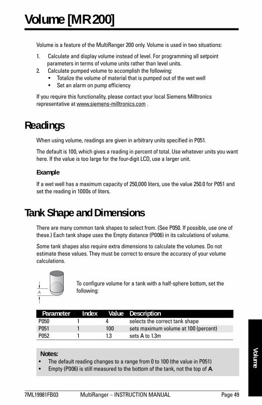
7ML19981FB03 MultiRanger � INSTRUCTION MANUAL Page 49
mm
mm
m
Volume
Volume [MR 200]
Volume is a feature of the MultiRanger 200 only. Volume is used in two situations:
1. Calculate and display volume instead of level. For programming all setpoint parameters in terms of volume units rather than level units.
2. Calculate pumped volume to accomplish the following:� Totalize the volume of material that is pumped out of the wet well� Set an alarm on pump efficiency
If you require this functionality, please contact your local Siemens Milltronics representative at www.siemens-milltronics.com .
ReadingsWhen using volume, readings are given in arbitrary units specified in P051.
The default is 100, which gives a reading in percent of total. Use whatever units you want here. If the value is too large for the four-digit LCD, use a larger unit.
Example
If a wet well has a maximum capacity of 250,000 liters, use the value 250.0 for P051 and set the reading in 1000s of liters.
Tank Shape and DimensionsThere are many common tank shapes to select from. (See P050. If possible, use one of these.) Each tank shape uses the Empty distance (P006) in its calculations of volume.
Some tank shapes also require extra dimensions to calculate the volumes. Do not estimate these values. They must be correct to ensure the accuracy of your volume calculations.
To configure volume for a tank with a half-sphere bottom, set the following:
Parameter Index Value DescriptionP050 1 4 selects the correct tank shapeP051 1 100 sets maximum volume at 100 (percent)P052 1 1.3 sets A to 1.3m
Notes: � The default reading changes to a range from 0 to 100 (the value in P051)� Empty (P006) is still measured to the bottom of the tank, not the top of A.

Page 50 MultiRanger � INSTRUCTION MANUAL 7ML19981FB03
mm
mm
m
Volu
me
Characterization Chart [MR 200]If you cannot use a pre-defined tank, then use one of the universal tank shapes and program the characterization curve.
1. Plot a volume to height chart. Usually a tank supplier will provide this chart. However, if you have a custom-built wet well then you will need access to complete drawings of the well or accurate measurements.
2. Enter the curve values from this chart into P054 and P055. 3. Ensure extra points are added around sharp transitions in the wet well volume (e.g:
as steps in the well wall).
Example Chart
Note: The end points in the curve are 0,0 (fixed) and the point defined by P007�Span and P051�Maximum Volume.
FLOW
LEVEL (P054)0,0
VOLU
ME
(P05
5)
MAX VOLUME P051
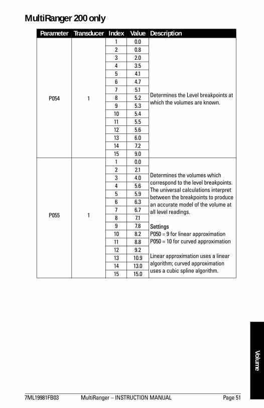
7ML19981FB03 MultiRanger � INSTRUCTION MANUAL Page 51
mm
mm
m
Volume
MultiRanger 200 only
Parameter Transducer Index Value Description
P054 1
1 0.0
Determines the Level breakpoints at which the volumes are known.
2 0.83 2.04 3.55 4.16 4.77 5.18 5.29 5.310 5.411 5.512 5.613 6.014 7.215 9.0
P055 1
1 0.0
Determines the volumes which correspond to the level breakpoints. The universal calculations interpret between the breakpoints to produce an accurate model of the volume at all level readings.
SettingsP050 = 9 for linear approximation P050 = 10 for curved approximation
Linear approximation uses a linear algorithm; curved approximation uses a cubic spline algorithm.
2 2.13 4.04 5.65 5.96 6.37 6.78 7.19 7.810 8.211 8.812 9.213 10.914 13.015 15.0

Page 52 MultiRanger � INSTRUCTION MANUAL 7ML19981FB03
mm
mm
m
Ala
rms
Alarms
LevelThe level alarm is the most common. Use this alarm to warn you when your process is in danger of being upset due to high or low levels.
Generally, the four alarms used are Hi, Hi Hi, Lo, and Lo Lo.
Set the Common Parameters
Prerequisite: You must know the details of your application and substitute the values for the sample values provided. If you are bench testing the unit, then set your test values to be the same as the sample values.
Parameter Index1
1. This example assumes a base, single measurement unit. If your unit has optional dual point software installed then some parameters are indexed by two.
Value DescriptionP001 G 1 Operation = levelP002 G 1 Material = liquidP003 G 2 Maximum Process Speed = mediumP004 G 102 Transducer = XPS-10P005 G 1 Units = metersP006 G 1.8 Empty = 1.8mP007 G 1.4 Span = 1.4m
P007
P006
lo lolo
hi
hi hi

7ML19981FB03 MultiRanger � INSTRUCTION MANUAL Page 53
mm
mm
m
Alarm
s
Setting Simple Level AlarmsTo set Relay Five to a standard level alarm (Hi Hi, Hi, Lo, Lo Lo) do the following:
Available designations:
Rate [MR 200]Rate alarms can trigger an alarm if the vessel is filling/emptying too quickly.
Setting a Filling Rate Alarm
Setting an Emptying Rate Alarm
Parameter Index Value DescriptionP111 5 1 � Set P111, indexed to relay, to the value 1 for level
alarm
� Press UNIT to display the Auxiliary Function symbol.
� Press ARROW keys as required to scroll
to the alarm designation ( , , , or ).
� Press ENTER to enter the value.P112 5 1.2m � Set the ON setpointP113 5 1.15m � Set the OFF setpoint
Alarm DesignationHi Hi
HiLo
Lo Lo
Parameter Index Value DescriptionP111 5 4 These settings trip the alarm when the
reservoir is filling faster than 1m per minute and reset it at 0.9m per minute.
P112 5 1mP113 5 0.9m
Parameter Index Value DescriptionP111 5 4 These settings trip the alarm when the
reservoir is emptying faster than 10% of span per minute and reset the alarm when emptying falls to 5%.
P112 5 -10%P113 5 -5%

Page 54 MultiRanger � INSTRUCTION MANUAL 7ML19981FB03
mm
mm
m
Ala
rms
In Bounds/ Out of Bounds Range [MR 200]Use the bounded range alarms to detect when the level is inside or outside of the range. By using a bounded range alarm, you can effectively put two level alarms (high and low) on one relay.
Setting an Out of Bounds Alarm
Results:
� Trips alarm above 1.35 m and below 0.25m� Resets alarm below 1.25 m and above 0.35m
Setting an In Bounds Alarm
Results:
� Trips alarm below 1.25 m and above 0.35 m� Resets alarm above 1.35 m and below 0.25 m
Cable FaultActivates an alarm if transducer cable circuit enters a shorted or opened state.
Temperature [MR 200]Use the temperature alarm to activate an alarm when the temperature reaches the ON setpoint (P112). This alarm uses the same setpoint parameters as the level alarms (P112 and P113).
Parameter Index ValueP111 5 3P112 5 1.3P113 5 0.3P116 5 0.05
Parameter Index ValueP111 5 2P112 5 1.3P113 5 0.3P116 5 0.05
Parameter Index Value DescriptionP111 5 7 Alarm on transducer cable faultP110 5 1 Alarm on Transducer One

7ML19981FB03 MultiRanger � INSTRUCTION MANUAL Page 55
mm
mm
m
Alarm
s
With P112 and P113, you can set a high alarm (P112 > P113) or a low alarm (P112 < P113).
This shows a high alarm:
The temperature source can be the temperature sensor built into the transducer or an external TS-3, as set by P660.
Loss of Echo (LOE)
Parameter Index Value DescriptionP111 5 5 Alarm on temperatureP112 5 45 ON setpoint at 45 °CP113 5 43 OFF setpoint at 43 °CP110 5 1 Take the temperature reading from
Transducer One
Parameter Index Value DescriptionP110 5 1 Alarm on LOE for Transducer OneP111 5 6 Alarm on LOEP070 G 0.5 Trip alarm when 0.5 minutes (30 seconds)
pass without detecting a valid echo.
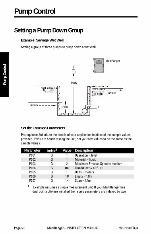
Page 56 MultiRanger � INSTRUCTION MANUAL 7ML19981FB03
mm
mm
m
Pum
p Co
ntro
l
Pump Control
Setting a Pump Down GroupExample: Sewage Wet Well
Setting a group of three pumps to pump down a wet well.
Set the Common Parameters
Prerequisite: Substitute the details of your application in place of the sample values provided. If you are bench testing the unit, set your test values to be the same as the sample values.
Parameter Index1
1. Example assumes a single measurement unit. If your MultiRanger has dual point software installed then some parameters are indexed by two.
Value DescriptionP001 G 1 Operation = levelP002 G 1 Material = liquidP003 G 2 Maximum Process Speed = mediumP004 G 102 Transducer = XPS-10P005 G 1 Units = metersP006 G 1.8 Empty = 1.8mP007 G 1.4 Span = 1.4m
MultiRanger
P006
P007Inflow
Outflow

7ML19981FB03 MultiRanger � INSTRUCTION MANUAL Page 57
mm
mm
m
Pump Control
Set Relays to ALTERNATE DUTY ASSIST
Set the ON Setpoints
Set the OFF Setpoints
Setting a Pump Up (Reservoir) GroupSets a group of three pumps to pump up a reservoir.
Parameter Index Value DescriptionP111 1 52
Sets the pump relays (index 1, 2, and 3) to ALTERNATE DUTY ASSIST.P111 2 52
P111 3 52
Parameter Index Value DescriptionP112 1 1.0m Sets the three setpoints for the pump relays.
The first cycle will use these setpoints. Subsequent cycles rotate the setpoints among the pumps.
P112 2 1.1mP112 3 1.2m
Parameter Index Value DescriptionP113 0 0.5m By using index 0 all six relays are set at the
same time, including any alarm relays. Use with caution.
P006
P007Inflow
Outflow
MultiRanger

Page 58 MultiRanger � INSTRUCTION MANUAL 7ML19981FB03
mm
mm
m
Pum
p Co
ntro
lSet the Common Parameters
Prerequisite: Substitute the details of your application in place of the sample values provided. If you are bench testing the unit, set your test values to be the same as the sample values.
Set Relays to ALTERNATE DUTY ASSIST
Set the Relay ON Setpoints
Set the Relay OFF Setpoints
For more information, see Appendix D: Pump Control Reference on page 239.
Parameter Index1
1. Example assumes a single measurement unit. If your MultiRanger has dual point software installed, some parameters are indexed by two.
Value DescriptionP001 G 1 Operation = levelP002 G 1 Material = liquidP003 G 2 Maximum Process Speed = mediumP004 G 102 Transducer = XPS-10P005 G 1 Units = metersP006 G 1.8 Empty = 1.8mP007 G 1.4 Span = 1.4m
Parameter Index Value DescriptionP111 1 52
Sets the pump relays (index 1, 2, and 3) to ALTERNATE DUTY ASSIST.P111 2 52
P111 3 52
Parameter Index Value DescriptionP112 1 0.4m Sets the three setpoints for the pump relays.
The first cycle will use these setpoints. Subsequent cycles rotate the setpoints among the pumps.
P112 2 0.3mP112 3 0.2m
Parameter Index Value DescriptionP113 0 1.3m By using index 0 all six relays are set at the
same time, including any alarm relays. Use with caution.

7ML19981FB03 MultiRanger � INSTRUCTION MANUAL Page 59
mm
mm
m
Pump Control
Other Pump Control Algorithms
Set Relays to ALTERNATE DUTY BACKUP [MR 200]
Set the Relay ON Setpoints [MR 200]
Set the Relay OFF Setpoints [MR 200]
Set Relays to FIXED DUTY ASSIST
Set the Relay ON Setpoints
Set the Relay OFF Setpoints
Parameter Index Value DescriptionP111 1 53
Sets the pump relays (index 1, 2, and 3) to ALTERNATE DUTY BACKUP.P111 2 53
P111 3 53
Parameter Index Value DescriptionP112 1 0.4m Sets the three setpoints for the pump relays.
The first cycle will use these setpoints. Subsequent cycles rotate the setpoints among the pumps.
P112 2 0.3mP112 3 0.2m
Parameter Index Value DescriptionP113 0 1.3m By using index 0 all six relays are set at the
same time, including any alarm relays. Use with caution.
Parameter Index Value DescriptionP111 1 50 Sets the pump relays (index 1, 2, and 3) to
FIXED DUTY ASSIST. Multiple pumps can run simultaneously.
P111 2 50P111 3 50
Parameter Index Value DescriptionP112 1 0.4m Sets the three setpoints for the pump relays.
The first cycle will use these setpoints. Subsequent cycles rotate the setpoints among the pumps.
P112 2 0.3mP112 3 0.2m
Parameter Index Value DescriptionP113 0 1.3m By using index 0 all six relays are set at the
same time, including any alarm relays. Use with caution.
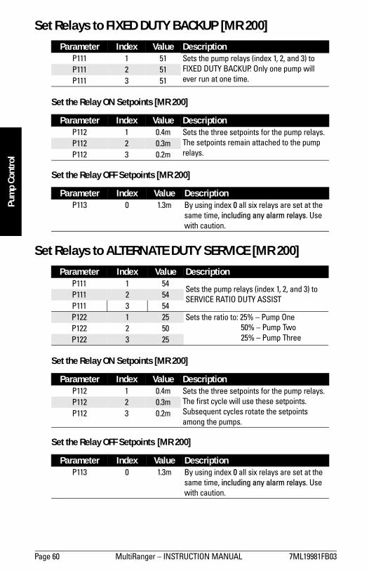
Page 60 MultiRanger � INSTRUCTION MANUAL 7ML19981FB03
mm
mm
m
Pum
p Co
ntro
l
Set Relays to FIXED DUTY BACKUP [MR 200]
Set the Relay ON Setpoints [MR 200]
Set the Relay OFF Setpoints [MR 200]
Set Relays to ALTERNATE DUTY SERVICE [MR 200]
Set the Relay ON Setpoints [MR 200]
Set the Relay OFF Setpoints [MR 200]
Parameter Index Value DescriptionP111 1 51 Sets the pump relays (index 1, 2, and 3) to
FIXED DUTY BACKUP. Only one pump will ever run at one time.
P111 2 51P111 3 51
Parameter Index Value DescriptionP112 1 0.4m Sets the three setpoints for the pump relays.
The setpoints remain attached to the pump relays.
P112 2 0.3mP112 3 0.2m
Parameter Index Value DescriptionP113 0 1.3m By using index 0 all six relays are set at the
same time, including any alarm relays. Use with caution.
Parameter Index Value DescriptionP111 1 54
Sets the pump relays (index 1, 2, and 3) to SERVICE RATIO DUTY ASSISTP111 2 54
P111 3 54P122 1 25 Sets the ratio to: 25% � Pump One
50% � Pump Two25% � Pump Three
P122 2 50P122 3 25
Parameter Index Value DescriptionP112 1 0.4m Sets the three setpoints for the pump relays.
The first cycle will use these setpoints. Subsequent cycles rotate the setpoints among the pumps.
P112 2 0.3mP112 3 0.2m
Parameter Index Value DescriptionP113 0 1.3m By using index 0 all six relays are set at the
same time, including any alarm relays. Use with caution.

7ML19981FB03 MultiRanger � INSTRUCTION MANUAL Page 61
mm
mm
m
Pump Control
Set Relays to FIRST IN FIRST OUT (FIFO) ASSIST [MR 200]
Set the Relay ON Setpoints [MR 200]
Set the Relay OFF Setpoints [MR 200]
Optional Pump Controls
Starting Pumps by Rate of Level Change [MR 200]Use this function when multiple pumps will be controlled by rate of level change rather than setpoints. Pumping costs can be reduced because only the highest ON setpoint needs to be programmed. This results in a lower difference in head to the next wet well which, in turn, results in less energy being used to pump out the well.
Parameter Index Value DescriptionP111 1 56 Sets the pump relays (index 1, 2, and 3) to
FIFO DUTY ASSIST.P111 2 56P111 3 56
Parameter Index Value DescriptionP112 1 0.4m Sets the three setpoints for the pump relays.
The first cycle will use these setpoints. Subsequent cycles rotate the setpoints among the pumps.
P112 2 0.3mP112 3 0.2m
Parameter Index Value DescriptionP113 0 1.3m By using index 0 all six relays are set at the
same time, including any alarm relays. Use with caution.
Parameter Index Value DescriptionP112 1 1.35 Starting pumps by rate allows all setpoints to
be set higher to save money by pumping from the highest safe level of the wet well.
Notice that all indexed relays for both P112 and P113 are set to the same levels.
The pumps will start on 20 second intervals until the rate set in P703 is met.
P112 2 1.35P112 3 1.35P113 1 0.5mP113 2 0.5mP113 3 0.5mP121 1 1P121 2 1P121 3 1P132 G 20.0

Page 62 MultiRanger � INSTRUCTION MANUAL 7ML19981FB03
mm
mm
m
Pum
p Co
ntro
lWhen the first ON setpoint is reached, the pumps will start, one by one, until the material level rate of change is set at the same value or greater than the value in:
� P703 � Emptying Indicator (pump down applications)� P702 � Filling Indicator (pump up applications)
Set delay between pump starts using P132 � Pump Start Delay.
Single and Dual Point [MR 200]
� Single Point Mode: one pump by rate control available that affects all pumps.� Dual Point Mode: a single pump by rate control can be set up for each of the three
available level points. Set Operation for difference or average (P001 = 4 or 5).
Rotating Pumps by Service Ratio [MR 200]
Prerequisite: Set pump relays to a service ratio value (P111 = 54 or 55).
When more than one pump is assigned a Pump Service Ratio value (in any time units) and a pump start is required (P112 Relay Setpoint ON), the pump with the fewest running hours (with respect to the assigned ratio values) starts.
Conversely, when a pump stop is required (113 Relay Setpoint OFF), the pump with the most running hours (as compared to the assigned ratio values) stops.
Parameter Index Value DescriptionP122 1 1 These values will start Pump Two 50% of the
time and Pumps One and Three each 25% of the time.
P122 2 2P122 3 1
Notes: � Set all pump control relay ON and OFF setpoints to the same value� If the level is within 5% of Span (P007) of the OFF setpoint, then the next pump is
not started
Notes: � The MultiRanger will not sacrifice other pumping strategies to ensure that the ratio
is held true� If the pump relays are set to the same value, then the ratio equals 1:1 and all pumps
are used equally (preset)

7ML19981FB03 MultiRanger � INSTRUCTION MANUAL Page 63
mm
mm
m
Pump Control
Totalizing Pumped Volume [MR 200]Prerequisite: the volume of the vessel must be known.
Set in RUN Mode
1. Press PROGRAM for RUN mode.
2. Press TOGGLE to display pumped volume on the totalizer.
3. Press AUXILIARY to display current level in the auxiliary reading area.
Setting Independent Failsafe ControlsIndependent failsafe controls allow you to vary an individual relay from the global failsafe controls programmed in P070 to P072.
Example:
The global failsafe controls are set to hold and Relay Five is set to trigger an alarm bell.
Parameter Index Value DescriptionP001 G 7 Operation = pumped volumeP002 G 1
These parameters are as shown above.
P003 G 2P004 G 102P005 G 1P006 G 1.8P007 G 1.4P050 G 1 Tank shape is Flat Bottom.P051 G 17.6 Max volume is 17.6m3 or 17,600 liters.P111 1 52 Sets relays 1, 2, and 3 as a pump group using
ALTERNATE DUTY ASSIST CONTROL.P111 2 52P111 3 52P112 1 1.0
Sets the ON setpoints for the pump group.P112 2 1.2P112 3 1.4P113 0 0.2 Sets the OFF setpoints for the pump group.
Parameter Index Value DescriptionP071 G HOLd Keep level at last known value.P129 5 dE De-energize Relay Five, and trigger alarm.
P

Page 64 MultiRanger � INSTRUCTION MANUAL 7ML19981FB03
mm
mm
m
Pum
p Co
ntro
l
Setting a Pump to Run On [MR 200]When you need to pump below the normal OFF setpoint, use P130 (Pump Run-On Interval) and P131 (Pump Run-On Duration) to control this event.
Example:
The pump connected to Relay Three is set to pump for an extra 60 seconds every five times it is triggered.
Setting the Pump Start Delays [MR 200]The pump start delay ensures that all of the pumps do not start at once to avoid power surges. There are two parameters used here: P132�Pump Start Delay and P133�Pump Power Resumption Delay. The default is 10 seconds but you can increase this if your pumps take longer to spin up.
Example:
The delay between pumps is set to 20 seconds and the delay of the first pump is set to 30 seconds.
Reducing Wall Cling [MR 200]Use the Wall Cling parameter to randomly alter the ON and OFF setpoints over a range. This eliminates the ridge of material that builds up at the setpoint that can give false echoes.
This setting may increase the number of days between trips to clean the wet well.
Wall cling reduction is set by P136. The relay setpoints ON and OFF are randomly varied inside a range so the material level does not stop at the same point.
Parameter Index Value DescriptionP130 3 5 Wait for Relay Three to pump five times and
then run-on.P131 3 60 Run-on for 60 seconds.
Parameter Index Value DescriptionP132 G 20 Wait at least 20 seconds between pump
starts.P133 G 30 Wait for 30 seconds when power is restored.
Note: P130 counts when the indexed relay is tripped, not the number of pump cycles. If the indexed relay only trips once every four pump cycles then the actual interval of the run-on will be 20 pump cycles, or five cycles of Relay Three.

7ML19981FB03 MultiRanger � INSTRUCTION MANUAL Page 65
mm
mm
m
Pump Control
Example [MR 200]:
A range of 0.5 meters is used to vary the setpoint. The randomly-selected setpoints are always inside the ON and OFF setpoints.
Grouping Pumps [MR 200]You can group pumps and use the same pumping algorithm separately on each group. If you specify different pumping algorithms then the pumps are already grouped by algorithm and you do not need to use this parameter.
Group pumps only when four pumps are using the same algorithm and you want to split them into two groups.
Example:
Pumps One and Two can operate as a group and Pumps Three and Four can operate as another group.
Setting a Flush Valve [MR 200]A flush valve stirs up the sediment on the bottom of the well during pumping so that it doesn�t accumulate. These parameters will control any relays set with P111 = 64 (Flush Valve).
Most sets of parameters will work with only one or two changes; however, for these parameters to work, all of them must be set to a value.
Parameter Index Value DescriptionP137 1 1 Groups Pumps One and TwoP137 2 1P137 3 2 Groups Pumps Three and FourP137 4 2
Random Setpoint Range
Level Setpoint ON
Wall Cling Value
Level Setpoint OFF

Page 66 MultiRanger � INSTRUCTION MANUAL 7ML19981FB03
mm
mm
m
Pum
p Co
ntro
lExample:
The flush valve connects to Relay Four and the watched pump is on Relay One.
Relay Controlled by Communications A relay can be controlled directly by a remote system through communications. No other control schemes can then be used with a relay configured this way. Communications can be used to force status of some control relays, such as pumps.
Settings:
Tracking Pump UsageYou can find out how much an individual pump has been used by viewing the pump records parameters.
Parameter Index Value DescriptionP170 G 1 Watch Relay One to count pump cycles.P171 G 3 Open the flush valve for 3 cycles.P172 G 10 Use the flush value every 10 cycles.P173 G 120 Open the flush valve for 120 seconds.
Parameter Index Value DescriptionP111 5 65 Sets Relay Five to communications control.
Information Available Parameter AccessCurrent RUN time P309Total pump hours P310Total pump starts P311Total pump RUN on occurrences P312 [MR 200 ONLY]

7ML19981FB03 MultiRanger � INSTRUCTION MANUAL Page 67
mm
mm
m
Rake (Screen) ControlM
R 200
Rake (Screen) Control [MR 200]
This feature is only available on the MultiRanger 200.
Screens or rakes are mounted on the inflow channel of the wastewater treatment plant to prevent debris from clogging the equipment.
When material builds up on the screen, a level differential is created, and the water level is higher in front of the screen than behind it. When this differential reaches the programmed setpoint, the MultiRanger activates a relay to operate mechanical rakes that clean the screen and ensure a steady flow.
Setting a Rake ControlTransducer
TwoTransducer One Rake
Transducer[1]
P006[1]
h[1]Rake
Debris Conveyer Transducer[2]
P006[2]
P007[2]
Water Level h[2]
P007[1]
Flow
Point Three: Level Distance = h[1] �h[2]
Note: transducers may be mounted at variant heights.
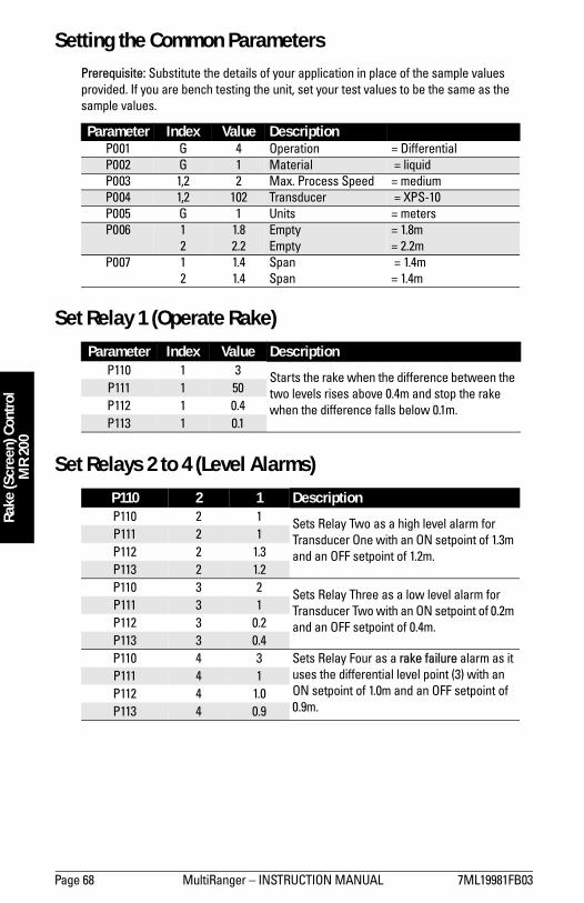
Page 68 MultiRanger � INSTRUCTION MANUAL 7ML19981FB03
Rake
(Scr
een)
Con
trol
MR
200
Setting the Common ParametersPrerequisite: Substitute the details of your application in place of the sample values provided. If you are bench testing the unit, set your test values to be the same as the sample values.
Set Relay 1 (Operate Rake)
Set Relays 2 to 4 (Level Alarms)
Parameter Index Value DescriptionP001 G 4 Operation = DifferentialP002 G 1 Material = liquidP003 1,2 2 Max. Process Speed = mediumP004 1,2 102 Transducer = XPS-10P005 G 1 Units = metersP006 1
21.82.2
EmptyEmpty
= 1.8m= 2.2m
P007 12
1.41.4
SpanSpan
= 1.4m = 1.4m
Parameter Index Value DescriptionP110 1 3 Starts the rake when the difference between the
two levels rises above 0.4m and stop the rake when the difference falls below 0.1m.
P111 1 50P112 1 0.4P113 1 0.1
P110 2 1 DescriptionP110 2 1 Sets Relay Two as a high level alarm for
Transducer One with an ON setpoint of 1.3m and an OFF setpoint of 1.2m.
P111 2 1P112 2 1.3P113 2 1.2P110 3 2 Sets Relay Three as a low level alarm for
Transducer Two with an ON setpoint of 0.2m and an OFF setpoint of 0.4m.
P111 3 1P112 3 0.2P113 3 0.4P110 4 3 Sets Relay Four as a rake failure alarm as it
uses the differential level point (3) with an ON setpoint of 1.0m and an OFF setpoint of 0.9m.
P111 4 1P112 4 1.0P113 4 0.9
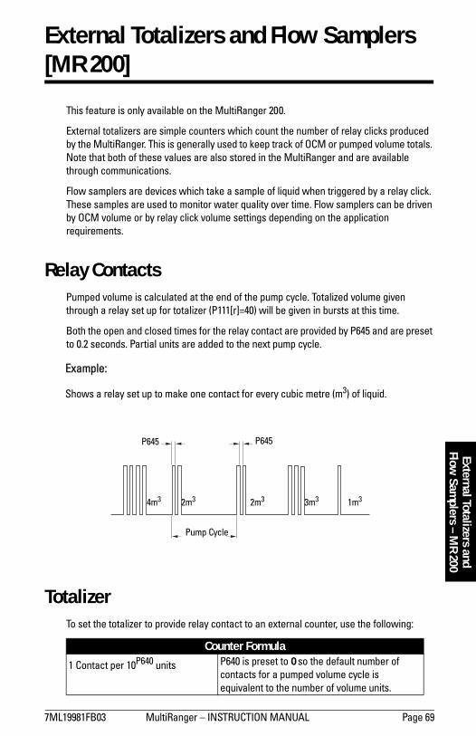
7ML19981FB03 MultiRanger � INSTRUCTION MANUAL Page 69
mm
mm
m
External Totalizers and Flow
Samplers – M
R 200External Totalizers and Flow Samplers [MR 200]
This feature is only available on the MultiRanger 200.
External totalizers are simple counters which count the number of relay clicks produced by the MultiRanger. This is generally used to keep track of OCM or pumped volume totals. Note that both of these values are also stored in the MultiRanger and are available through communications.
Flow samplers are devices which take a sample of liquid when triggered by a relay click. These samples are used to monitor water quality over time. Flow samplers can be driven by OCM volume or by relay click volume settings depending on the application requirements.
Relay ContactsPumped volume is calculated at the end of the pump cycle. Totalized volume given through a relay set up for totalizer (P111[r]=40) will be given in bursts at this time.
Both the open and closed times for the relay contact are provided by P645 and are preset to 0.2 seconds. Partial units are added to the next pump cycle.
Example:
Shows a relay set up to make one contact for every cubic metre (m3) of liquid.
TotalizerTo set the totalizer to provide relay contact to an external counter, use the following:
Counter Formula
1 Contact per 10P640 units P640 is preset to 0 so the default number of contacts for a pumped volume cycle is equivalent to the number of volume units.
P645 P645
4m3 2m3 2m3 3m3 1m3
Pump Cycle

Page 70 MultiRanger � INSTRUCTION MANUAL 7ML19981FB03
mm
mm
m
Exte
rnal
Tot
aliz
ers
and
Flow
Sam
pler
s –
MR
200
The source of units depends on the operation:
Flow Sampler
Based on Volume and TimeTo trigger a flow sampler relay based on flow, use P111[r]=41 and set the other parameters:
By using a mantissa (P641) and an exponent (P642), the relay contacts can be based on a volume other than a multiple of ten.
During the periods of low flow, the sampler may be idle for lengths of time. Program P115 to a time interval in hours to drive the sampler. The sampler will operate based on the volume of flow or the time interval, whichever comes first.
Operation Units Source ParameterOCM (P001=6) P604�Maximum Flow, or P608�Flowrate UnitsPumped Volume (P001=7) P051�Max Volume
Counter Formula
1 Contact per P641 x 10P642 units
Operation Units Source ParameterOCM (P001=6) P604 � Maximum Flow, or P608 � Flowrate Units

7ML19981FB03 MultiRanger � INSTRUCTION MANUAL Page 71
mm
mm
m
Open Channel M
onitoringM
R 200
Open Channel Monitoring (OCM) [MR 200]
An OCM installation is defined one of three ways, based on the Primary Measuring Device (PMD):
1. Dimensional (P600 = 2,3,6,7)
For some common weir and flume types. PMD dimensions (P602) are entered directly.
� BS-3680 / ISO 1438/1 Thin plate V notch weir on page 73� BS-3680 / ISO 4359 Rectangular Flume on page 74� Palmer Bowlus Flume on page 75 � H Flume on page 76
2. Exponential (P600 = 1)
For most other weir and flume types. PMD exponents provided by the manufacturer are entered. Flow is calculated using the exponent (P601) and the maximum values (P603 and P604).
� Standard Weirs on page 77� Parshall Flume on page 78� Leoplod Lagco on page 79� Cut Throat Flume on page 80
3. Universal (P600 = 4,5)
For all other PMDs, the head-to-flow curve can be plotted based on known breakpoints, usually supplied by the PMD manufacturer.
� Typical Flow Characterization on page 81� Example Flumes on page 82� Example Weirs on page 82
Common ParametersThese Quick Start parameters are required for all installations.
Parameter Index Value DescriptionP001 G 6 Operation = OCMP002 G 1 Material = liquidP003 G 2 Max. Process Speed = mediumP004 G 102 Transducer = XPS-10P005 G 1 Units = metersP006 G 1.8 Empty = 1.8mP007 G 1.0 Span = 1.4mP801 G 0.8 Range Extension to avoid LOE

Page 72 MultiRanger � INSTRUCTION MANUAL 7ML19981FB03
mm
mm
m
Ope
n Ch
anne
l Mon
itorin
gM
R 20
0Setting Zero Head
Many PMDs start flowing higher than the traditional empty distance of the application. You can account for the flow in one of two ways:
1. Use P605 (Zero Head) to have OCM calculations ignore levels below that value. Possible head = P007 minus P605.
2. Use P801 Range Extension where the Empty level is set to the bottom of the weir, and above the bottom of the channel. It should be used if the surface monitored can fall past the Empty (P006) level in normal operation without reporting an LOE. The value is added to Empty (P006) and can be greater than the range of the transducer.
The examples on the following pages show both methods.
Note: P603 (Max. Head) is preset to P007 and is not updated when P605 is used. Make sure you set P603 to the correct value when using P605.
P006
P007
P605P603
P006
P801
P007
P603
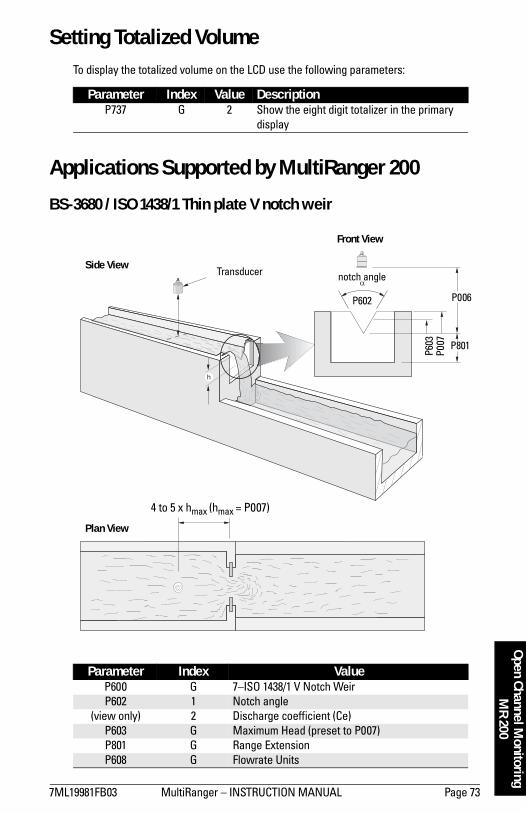
7ML19981FB03 MultiRanger � INSTRUCTION MANUAL Page 73
mm
mm
m
Open Channel M
onitoringM
R 200Setting Totalized Volume
To display the totalized volume on the LCD use the following parameters:
Applications Supported by MultiRanger 200
BS-3680 / ISO 1438/1 Thin plate V notch weir
Parameter Index Value DescriptionP737 G 2 Show the eight digit totalizer in the primary
display
Parameter Index ValueP600 G 7�ISO 1438/1 V Notch WeirP602 1 Notch angle
(view only) 2 Discharge coefficient (Ce)P603 G Maximum Head (preset to P007)P801 G Range ExtensionP608 G Flowrate Units
P801
P006
Transducer
4 to 5 x hmax (hmax = P007)
Plan View
Side View
Front View
P602
notch angle
P603
P007

Page 74 MultiRanger � INSTRUCTION MANUAL 7ML19981FB03
mm
mm
m
Ope
n Ch
anne
l Mon
itorin
gM
R 20
0BS-3680 / ISO 4359 Rectangular Flume
Parameter Index ValueP600 G 6�ISO 4359 Rectangular FlumeP602 1 Approach width (B)
2 Throat width (b)3 Hump Height (p)4 Throat length (L)
(view only) 5 Velocity coefficient (Cv)(view only) 6 Discharge coefficient (Cd)(view only) 7 Cross sectional area
P605 G Zero HeadP608 G Flowrate Units
h Diagonal View
Plan View 4 to 5 x hmax (hmax = P007)
L
Flow
Transducer
P006h
P605 (p)
Flow
Front View Side View
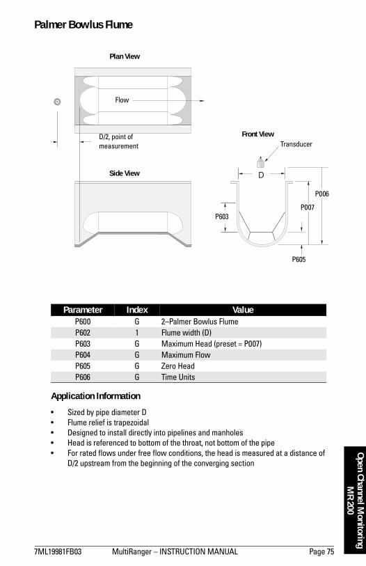
7ML19981FB03 MultiRanger � INSTRUCTION MANUAL Page 75
mm
mm
m
Open Channel M
onitoringM
R 200Palmer Bowlus Flume
Application Information
� Sized by pipe diameter D� Flume relief is trapezoidal� Designed to install directly into pipelines and manholes� Head is referenced to bottom of the throat, not bottom of the pipe� For rated flows under free flow conditions, the head is measured at a distance of
D/2 upstream from the beginning of the converging section
Parameter Index ValueP600 G 2�Palmer Bowlus FlumeP602 1 Flume width (D)P603 G Maximum Head (preset = P007)P604 G Maximum FlowP605 G Zero HeadP606 G Time Units
P006
P007
P605
P603
TransducerD/2, point of measurement
Flow
Plan View
Front View
Side View

Page 76 MultiRanger � INSTRUCTION MANUAL 7ML19981FB03
mm
mm
m
Ope
n Ch
anne
l Mon
itorin
gM
R 20
0H Flume
� Sized by maximum depth of flume� Approach is preferably rectangular, matching width and depth for distance 3 to 5
times the depth of the flume� May be installed in channels under partial submergence (ratio of downstream level
to head). Typical errors are:� 1% @ 30% submergence� 3% @ 50% submergence
� For rated flows under free flow conditions, the head is measured at a point downstream from the flume entrance
� H flumes come with a flat or sloping floor. The same flow table can be used because error is less than 1%.
Parameter Index ValueP600 G 3�H FlumeP602 1 Flume height (D)P603 G Maximum Head (preset = P007)P604 G Maximum FlowP606 G Time Units
Flume Size(Diameter in feet)
Point of Measurementcm inches
0.5 5 1¾0.75 7 2¾1.0 9 3¾1.5 14 5½2.0 18 7¼2.5 23 93.0 28 10¾4.5 41 16¼
Flow
D
Front View Side View
Point of Measurement
Transducer
P006P007
Plan View

7ML19981FB03 MultiRanger � INSTRUCTION MANUAL Page 77
mm
mm
m
Open Channel M
onitoringM
R 200PMDs with Exponential Flow to Head Function
For Primary Measuring Devices (PMDs) that measure flow by an exponential equation, use these parameters. Ensure that you use the correct exponent for your PMD; the values below are samples only.
Standard Weirs
Applicable Weir Profiles
Parameter Index ValueP600 G 1 - Exponential FunctionP601 G Weir Type Value1
1. Values are samples only. Consult weir manufacturer�s documentation for correct flow exponent.
V-notchSuppressed rectangularCipolletti or trapezoidalSutro or proportional
2.501.501.501.00
P603 G Maximum HeadP604 G Maximum FlowP606 G Time UnitsP801 G Range Extension
h
3 to 4 hmax
Weir Profile
Transducer
V-notch or triangular
suppressedrectangular
cipolleti or trapezoidal
sutro orproportional

Page 78 MultiRanger � INSTRUCTION MANUAL 7ML19981FB03
mm
mm
m
Ope
n Ch
anne
l Mon
itorin
gM
R 20
0Non-Applicable Weir Profiles
Flows through these weirs can be measured using the Universal Flow Calculation P600 = 4 or 5. See Universal Calculation Support on page 81.
Parshall Flume
Application Information
� Sized by throat width� Set on solid foundation� For rated flows under free flow conditions, the head is measured at 2/3 the length of
the converging section from the beginning of the throat section
Parameter Index ValueP600 G 1�Parshall FlumeP601 G 1.22�1.607 (consult your flume documentation)P603 G Maximum HeadP604 G Maximum Flow (Q)P606 G Time Units
contractedrectangular
compound Poebing approximate exponential
Note: C = Converging Dimension.
Flow
C 2/3 C
P006
Front View
Plan View
Transducer
Side View

7ML19981FB03 MultiRanger � INSTRUCTION MANUAL Page 79
mm
mm
m
Open Channel M
onitoringM
R 200Leopold Lagco Flume
Application Information
� Designed to be installed directly into pipelines and manholes� Leopold Lagco may be classed as a rectangular Palmer-Bowlus flume� Sized by pipe (sewer) diameter� For rated flows under free flow conditions, the head is measured at a point
upstream referenced to the beginning of the converging section. Refer to the following table:
Parameter Index ValueP600 G 1�Leopold Lagco FlumeP601 G 1.55P603 G Maximum Head (preset P007)P604 G Maximum FlowP605 G Zero HeadP606 G Time Units
Point of Measurement
DivergingConverging
Front View
0 Head
Plan View
Side View
Transducer
Throat

Page 80 MultiRanger � INSTRUCTION MANUAL 7ML19981FB03
mm
mm
m
Ope
n Ch
anne
l Mon
itorin
gM
R 20
0
Cut Throat Flume
Application Information
� Similar to Parshall flume except that the floor is flat bottomed and throat has no virtual length.
� Refer to manufacturer�s specifications for flow equation and point of head measurement.
Flume Size(pipe diameter in inches)
Point of Measurementcm inches
4-12 2.5 115 3.2 1¼18 4.4 1¾21 5.1 224 6.4 2½30 7.6 342 8.9 3½48 10.2 454 11.4 4½60 12.7 566 14.0 5½72 15.2 6
Parameter Index ValueP600 G 1�Cut Throat FlumeP601 G 1.55P603 G Maximum Head (preset P007)P604 G Maximum FlowP606 G Time Units
Plan View

7ML19981FB03 MultiRanger � INSTRUCTION MANUAL Page 81
mm
mm
m
Open Channel M
onitoringM
R 200Universal Calculation Support
When the primary measuring device (PMD) doesn�t fit one of the standard types, it can be programmed using a universal characterization. When Universal is selected as the PMD type (P600), then both P610 and P611 must be entered to define the flow.
Two curve types are supported:
� P600 = 4�linear (piece wise linear)� P600 = 5�curved (cubic spline)
Both are shown in the following chart.
Typical Flow Characterization
Characterization is achieved by entering the head (P610) and corresponding flow (P611), either from empirical measurement or from the manufacturer's specification. Increasing the number of defined breakpoints will increase the accuracy of the flow measurement.
Breakpoints should be concentrated in areas exhibiting the higher degrees of non linear flow. A maximum of 32 breakpoints can be defined. The curve�s end point is always specified by the parameters Maximum Head (P603) and Maximum Flow (P604) for a maximum total of 33 breakpoints.
Use as many breakpoints as required by the complexity of your PMD.See Volume on page 49 for more information and parameters P610 and P611 for characterization.
Maximums (P603, P604)
Linear
Curved
Head (P610)
Flow
(P61
1)
Max. Flow
Zero Flow
Zero
Hea
d
Max
. Hea
d
Head Breakpoints
Flow
Bre
akpo
ints

Page 82 MultiRanger � INSTRUCTION MANUAL 7ML19981FB03
mm
mm
m
Ope
n Ch
anne
l Mon
itorin
gM
R 20
0Example Flumes
These example flumes would both require a universal calculation.
Trapezoidal
Dual Range (nested) Parshall
Example WeirsThese weirs could require universal calculation.
contracted rectangular
compound Poebing approximate exponential

7ML19981FB03 MultiRanger � INSTRUCTION MANUAL Page 83
mm
mm
m
Testing the Configuration
Testing the Configuration
After programming the unit, you must test the device to ensure that it performs to your specifications. This test can be run in simulation mode or by varying the level in the application. The latter is preferred as it more accurately represents running conditions. However, if it is not possible to do a physical test, a simulation will ensure that control programming is correct.
SimulationIn simulation mode, the LCD display reacts to the simulated level changes. Alarm relays will also react to the simulation, but any pump or control relays will not react.
To allow pump or control relays to operate on the simulated level, set P000 to �1.
Simulating a Single MeasurementAccess the appropriate parameter: (press PROGRAM and then key in the parameter number). Press TRANSDUCER five times to overcome Echo Lock (P711) if applicable: the associated Reading is displayed in the Parameter Value field, and any alarm relays are set accordingly.
To verify Reading calculations (P920 to P926)
1. Key in a material level in Units (P005) or % of Span (P007).2. Press ENTER to display the calculated Reading.3. Verify the calculated Reading. 4. To start a simulation from the level entered, press ARROW or .
Simulating a Level CycleStarting a (P920, P921, P922, or P923) simulation when level = 0:
1. Press ENTER to simulate level rise and fall. At the start of a simulation, the default rate is 1% of Span / second.
2. Press the ARROW or to adjust the simulated rate of rise or fall. The maximum rate is 4% of Span / second.

Page 84 MultiRanger � INSTRUCTION MANUAL 7ML19981FB03
mm
mm
m
Test
ing
the
Conf
igur
atio
n The effect of the ARROW key is determined by the state (rate of rise or fall) immediately before the key is pressed.
When the level rises to 100% or falls to 0%, it reverses direction at the same rate.
Checking Volume Characterization [MR 200]To confirm universal volume calculations (P050 = 9, 10) are correct:
1. Go to P920.2. Key in a level associated with a known volume.3. Press ENTER .4. Check the returned volume against the manufacturer�s chart.5. Change parameters P054 and P055, as required.6. Repeat steps 2 to 5 until the volume curve is verified.
Checking OCM Flow Characterization [MR 200]To confirm universal flow calculations (P600 = 4, 5) are accurate:
1. Go to P925.2. Enter a level with a known flow.3. Press ENTER .4. Check the returned flow against the manufacturer�s chart.5. Change parameters P610 and P611, as required.6. Repeat steps 2 to 5 until the flow curve is verified.
Action State (prior to pressing key) Effect
Press
Stop Rise at 1% of Span / second
Rise at 1% of Span / second Rise at 4% of Span / second (max.)
Rise at 4% of Span / second (max.) No effect
Fall at 1% of Span / second Stop
Fall at 4% of Span / second Fall at 1% of Span / second
Press
Stop Fall at 1% of Span / second
Rise at 1% of Span / second Stop
Rise at 4% of Span / second (max.) Rise at 1% of Span / second
Fall at 1% of Span / second Fall at 4% of Span / second (max.)
Fall at 4% of Span / second (max.) No effect

7ML19981FB03 MultiRanger � INSTRUCTION MANUAL Page 85
mm
mm
m
Testing the Configuration
I/O CheckoutAfter the unit is installed, test to verify the wiring.
Relays
Use P119 to force a state change and verify that the results are as expected (pump starts, alarm sounds, etc.).
Discrete Inputs
Use P270 to force the input value and verify that the results are as expected.
1. Go to P270 [DI] where DI = the discrete input to be tested2. Set P270 to 0 (forced OFF)3. Go to P275 [DI] to verify that the value is forced4. Check the state of outputs to ensure that they respond as expected5. Go to P270 [DI]6. Set P270 to 1 (forced ON)7. Go to P275 [DI] to verify that the value is forced8. Check the state of outputs to ensure that they respond as expected
For further information see Discrete Inputs section on page 46.
mA Input [MR 200]
Use P254 to test the mA input value against a true level. Use a trusted external mA source to generate the signal required for testing, and verify the incoming signal with P260. Check that the system responds as expected when the mA level is changed.
mA Output
Use an external device to test the mA output against the measured level. Check that the mA value changes to reflect the changes in the measured level.
Application TestIf you are testing the application by varying the material level (the preferred test method) make sure that none of the control devices is connected (or at least that no power is available to them).
If you are testing the application in simulation mode (and P000 is not �1), then control relays are not energized and the control devices can remain connected.
While the level is being cycled, check the results of the discrete inputs either by closing the circuit externally (preferred) or by using P270 Discrete Input Function to force the input ON or OFF. Try all possible combinations to thoroughly test the setup. For each combination, run a complete cycle to verify that the relays operate as expected.

Page 86 MultiRanger � INSTRUCTION MANUAL 7ML19981FB03
mm
mm
m
Test
ing
the
Conf
igur
atio
n Monitor system performance carefully, under all anticipated operating conditions.
1. When the MultiRanger performs exactly as required, programming is complete.
2. If alternate Reading units, Failsafe action, or relay operation is desired, update the parameters for the new functionality.
3. If the system performance experiences problems, see General Appendix C: Troubleshooting, on page 230.
If you cannot observe all possible operating conditions during the System Performance Evaluation, use the level simulation (see page 83) to verify programming.
When a simulation is run, alarm relays will react to the simulated level changes, but control relays will not react. You can set P000 to value �1 to trigger the control relays based on the simulated level.
Retest the system every time you adjust any control parameters.

7ML19981FB03 MultiRanger - INSTRUCTION MANUAL Page 87
mm
mm
m
Comm
unications
MultiRanger Communications
MultiRanger Communication SystemsThe MultiRanger is an integrated level controller capable of communicating process information to a Supervisory Control and Data Acquisition (SCADA) system, via a serial device such as a radio modem, leased line, or dial-up modem.
The standard MultiRanger supports the following two communication protocols:
Modbus
Modbus is an industry standard protocol used by SCADA and HMI systems. The MultiRanger uses Modbus to communicate via the RS-485 port. For a description of the Modbus protocol, contact your local Schneider representative.
Dolphin
Dolphin is a proprietary Siemens Milltronics protocol designed to be used with Dolphin Plus. For more information on Dolphin Plus or to obtain a copy of the software, please go to www.siemens-milltronics.com to contact your Siemens Milltronics representative.
Optional SmartLinx®CardsThe standard MultiRanger unit may also be enhanced with Siemens Milltronics SmartLinx® communication modules that provide an interface to popular industrial communication systems.
This manual only describes the built-in communications. For more information on SmartLinx, please consult the appropriate SmartLinx manual.
MultiRanger
Connection via radio modem, dial-up modem, or leased line modem

Page 88 MultiRanger � INSTRUCTION MANUAL 7ML19981FB03
mm
mm
m
Com
mun
icat
ions
Communication SystemsThe MultiRanger is capable of communicating with most SCADA systems, PLCs, and PCs. The supported protocols are:
� Modbus RTU/ASCII � base unit on RS-232 or RS-485 transport
� PROFIBUS DP � optional SmartLinx® module
� Allen-Bradley®1 Remote I/O � optional SmartLinx module
� DeviceNet® � optional SmartLinx module
Communication PortsThe MultiRanger comes with two communication ports on the base unit.
RS-232
The RJ-11 jack connects to a laptop computer for the following:
� initial setup� configuration� troubleshooting� periodic maintenance
RS-485
The RS-485 port on the terminal blocks connects into industrial communications wiring and has the following advantages:
� runs communications cable farther � allows multiple slave units on the network, addressed by P771 � Network Address
To communicate with equipment requiring RS-485 capability, Siemens Milltronics offers the RS-485 External Modem Kit. For more information, go to www.siemens-milltronics.com.
ModbusThe Modbus protocol is supported in the base unit and can be configured using the Communications parameters P770 to P782.
To set up communications with a Modbus RTU master device on port 2 using RS-485, set the following parameters:
1. Allen-Bradley is a registered trademark of Rockwell Automation.DeviceNet is a registered trademark of Open DeviceNet Vendor Association.
Port Connection Location Interface1 RJ-11 connector inside enclosure on main board RS-2322 terminal block terminal block RS-485

7ML19981FB03 MultiRanger - INSTRUCTION MANUAL Page 89
mm
mm
m
Comm
unications
SmartLinxOther protocols are available through optional SmartLinx communications modules. Details on how to install and program these modules are contained in the SmartLinx documentation.
Dolphin PlusDolphin Plus software makes it easy to record and compare parameter sets for all the MultiRangers in your company. Dolphin Plus uses a proprietary protocol called Dolphin to communicate with Siemens Milltronics instruments. This protocol is set when P770 = 1.
By default the settings for port 1 (RJ-11 connection) and Dolphin Plus match. These settings are:
Parameter Index Value DescriptionP770 2 3 Modbus RTU slaveP771 2 1 Network address, only used for RS-485P772 2 9.6 Data rate of 9600 baudP773 2 0 No parity, common settingP774 2 8 8 data bits, common settingP775 2 1 1 stop bit, common settingP778 2 0 No modem connectedP782 2 0 Index parameter values globally
Parameter Index Value DescriptionP700 1 1 DolphinP772 1 115.2 Data rate of 115.2 Kilo baudP773 1 0 No parity, common settingP774 1 8 8 data bits, common settingP775 1 1 1 stop bit, common setting
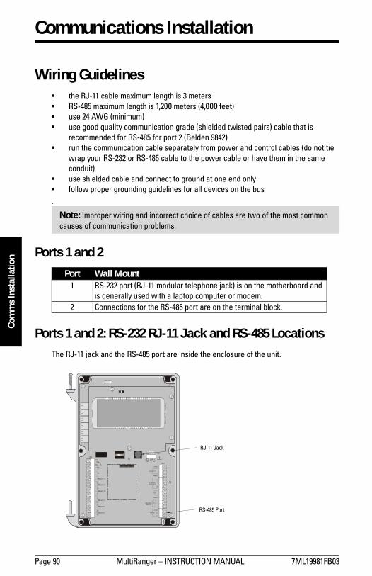
Page 90 MultiRanger � INSTRUCTION MANUAL 7ML19981FB03
mm
mm
m
Com
ms
Inst
alla
tion
Communications Installation
Wiring Guidelines� the RJ-11 cable maximum length is 3 meters� RS-485 maximum length is 1,200 meters (4,000 feet)� use 24 AWG (minimum)� use good quality communication grade (shielded twisted pairs) cable that is
recommended for RS-485 for port 2 (Belden 9842)� run the communication cable separately from power and control cables (do not tie
wrap your RS-232 or RS-485 cable to the power cable or have them in the same conduit)
� use shielded cable and connect to ground at one end only� follow proper grounding guidelines for all devices on the bus
�
Ports 1 and 2
Ports 1 and 2: RS-232 RJ-11 Jack and RS-485 LocationsThe RJ-11 jack and the RS-485 port are inside the enclosure of the unit.
Port Wall Mount1 RS-232 port (RJ-11 modular telephone jack) is on the motherboard and
is generally used with a laptop computer or modem.2 Connections for the RS-485 port are on the terminal block.
Note: Improper wiring and incorrect choice of cables are two of the most common causes of communication problems.
L2/N L1
TB1
TB3
TB2
RELAY 1
RELAY 2
RELAY 3
RELAY 4
RELAY 5
RELAY 6
2
1
mA INPUT
SHIELD
SYNC
1
2
4 - 20 mAOUTPUTS
TS-3
SHIELD
1
2DISCRETEINPUTS
RS485
B
A
COM
RJ-11 Jack
RS-485 Port

7ML19981FB03 MultiRanger � INSTRUCTION MANUAL Page 91
mm
mm
m
Comm
s Installation
Port 1: RS-232 RJ-11 Jack
To connect the unit to a PC using an RS-232 jack, use the cable as shown:
To connect the unit to a modem using an RS-232 jack:
Port 2: RS-485
To connect the unit to an RS-232 modem:
6
1
11
6
6
234
TxRxSG
RxTxSG
235
4678
5432
2345
16 16
16
6
1
Computer DB-9 (male)
RJ-11 jack
RJ-11 onMultiRanger
Modular cable with RJ-11 plug
RJ-11 to DB 9 converter
Note: Jumper pins 4-6 and 7-8 at the DB-9.
6
1
11
6
6
234
TxRxSG
RxTxSG
325
4678
5432
2345
16 16
16
6
1
RS-232 Modem
RJ-11 jack
RJ-11 onMultiRanger
Modular cable with RJ-11 plug
RJ-11 to DB 9 converter
Note: Jumper pins 4-6 and 7-8 at the DB-9.
B23 Tx
A32 RxCOM55RS-232
ModemConverter: RS-232 to RS-485
MultiRanger Terminal Block
DB 9DB 9

Page 92 MultiRanger � INSTRUCTION MANUAL 7ML19981FB03
mm
mm
m
Com
ms
Inst
alla
tion
To connect the unit to a modem using an RS-485 port:
Configuring Communication Ports (Parameters)The 11 parameters listed are indexed to the two communication ports, unless otherwise noted: An asterisk (*) identifies the preset value.
P770 Port Protocol
The communications protocol used between the MultiRanger and other devices.
The MultiRanger supports the Siemens Milltronics Dolphin format (www.siemens-milltronics.com), and the internationally recognized Modbus standard in both ASCII and RTU formats. Other protocols are available with optional SmartLinx cards.
Port Description1 RS-232 port (RJ-11 modular telephone)2 The RS-485 port is on the terminal blocks
Primary Index Communications Port
Values
0 Communications port disabled
1 * Siemens Milltronics Dolphin protocol (preset for port 1)
2 Modbus ASCII slave serial protocol
3 * Modbus RTU slave serial protocol (preset for port 2)
BACOM
(Shield to be grounded at one end)
MultiRanger Terminal Block
B
ACOM
MultiRanger Terminal Block
RS-485 Modem

7ML19981FB03 MultiRanger � INSTRUCTION MANUAL Page 93
mm
mm
m
Comm
s Installation
P771 Network AddressThe unique identifier of the MultiRanger on the network.
For devices connected with the Siemens Milltronics protocol, this parameter is ignored. For devices connected with a serial Modbus slave protocol, this parameter is a number from 1-247. The network administrator must ensure that all devices on the network have unique addresses. Do not use the value 0 for Modbus communications as this is the broadcast address and is inappropriate for a slave device.
P772 Baud RateThe communication rate with the master device.
This specifies the rate of communication in Kbaud. Any value may be entered, but the only values supported are those shown above. The baud rate should reflect the speed of the connected hardware and protocol used.
P773 ParityThe serial port parity.
Ensure that the communications parameters are identical between the MultiRanger and all connected devices, as many modems default to N-8-1.
P774 Data Bits
The number of data bits per character.
Primary Index Communications PortValues Range: 0 to 9999
1 * Preset
Primary Index Communications Port
Values4.8 4800 baud
9.6 9600 baud
19.2 * 19,200 baud (preset for port 2)
115.2 * 115,200 baud (preset for port 1)
Primary Index Communications Port
Values0 * No Parity
1 Odd Parity
2 Even Parity
Primary Index Communications Port
Values
Range: 5 to 8
8 * Modbus RTU
7 or 8 Modbus ASCII
7 or 8 Dolphin Plus
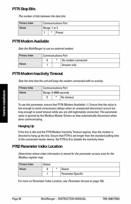
Page 94 MultiRanger � INSTRUCTION MANUAL 7ML19981FB03
mm
mm
m
Com
ms
Inst
alla
tion
P775 Stop Bits
The number of bits between the data bits.
P778 Modem Available
Sets the MultiRanger to use an external modem.
P779 Modem Inactivity Timeout
Sets the time that the unit will keep the modem connected with no activity.
To use this parameter, ensure that P778 (Modem Available) =1. Ensure that the value is low enough to avoid unnecessary delays when an unexpected disconnect occurs but long enough to avoid timeout while you are still legitimately connected. This parameter value is ignored by the Modbus Master Drivers as they automatically disconnect when done communicating.
Hanging Up
If the line is idle and the P779 Modem Inactivity Timeout expires, then the modem is directed to hang up the line. Ensure that P779 is set longer than the standard polling time of the connected master device. Set P779 to 0 to disable the inactivity timer.
P782 Parameter Index Location
Determines where index information is stored for the parameter access area for the Modbus register map.
For more on Parameter Index Location, see Parameter Access on page 100.
Primary Index Communications PortValues Range: 1 or 2
1 * Preset
Primary Index Communications Port
Values0 * No modem connected
1 Answer only
Primary Index Communications PortValues Range: 0-9999 seconds
0 * No timeout
Primary Index GlobalValues 0 * Global
1 Parameter-Specific

7ML19981FB03 MultiRanger � INSTRUCTION MANUAL Page 95
mm
mm
m
Modbus Register Types
Modbus Register Map
Features affecting volume, mA input, and Average or Difference readings apply to the MultiRanger 200 only. They are clearly marked.
The memory map of the MultiRanger occupies the Modbus holding registers (R40,001 and up). This map is used when the protocol is Modbus RTU slave or Modbus ASCII slave.
Register Map for Most Common Data
LegendType The type of data held in the group of registers.
Start The first register to hold the referenced data.
Data Type The possible values of the data in the register. See Data Types on page 105 for more information.
Description The type of data held in the individual registers.
#R The number of registers used for the referenced data.
Read/Write Indicates whether the register is readable, writeable or both.
Type Description Start #R 1
1. Maximum registers shown; fewer may be used depending on options installed.
Data Type Read/Write
Word Order 40,062 0/1 R/W
Map ID Register Map Type 40,063 1 0/1 = P782 R/W
ID Siemens Milltronics Product Code
40,064 1 4 = Model 2006 = Model 100
R
Single Parameter Access (SPA) R40,090 7 see Appendix A on page 113
Point Data
Reading (3)2
2. Varies according to model.MR 100: Available as reading 1 and reading 2 when in either Standard or Dual Point Mode. In Dual Point Mode, reading 1 and reading 2 are always available. MR 200: Available as reading 1, reading 2, and Average or Difference when in either Standard or Dual Point Mode. In Standard Mode, point 2 and 3 are only available if P001 = Average or Difference. In Dual Point Mode, reading 1 and reading 2 are always available. Point 3 is only available if P001[3]= Average or Difference.
41,010 2 -20,000 to 20,000 R
Volume (2)3[MR 200]
3. 2nd volume available in Dual Point Mode only.
41,020 2 -20,000 to 20,000 R

Page 96 MultiRanger � INSTRUCTION MANUAL 7ML19981FB03
mm
mm
m
Mod
bus
Regi
ster
Typ
es
The MultiRanger was designed to make it easy for master devices to get useful information via Modbus. This chart gives an overview of the different sections. A more detailed explanation of each section follows below.
Word Order (R40,062) This determines the format of unsigned, double-register integers (UINT32).
� 0 indicates that the most significant word (MSW) is given first� 1 indicates that the least significant word (LSW) is given first
See Unsigned Double Precision Integer (UINT32) on page 105 for more information.
Map ID (R40,063)This value identifies the register map used by the MultiRanger. See P782 Parameter Index Location on page 94.
See also Parameter Access (R43,998 � R46,999) on page 100 for details.
Type Description Start #R 1
1. Maximum registers shown; fewer may be used depending on options installed.
Data Type Read/Write
Point Data
Temperature (2) 41,0302
�50 to 150 R
I/O
Discrete Inputs (2) 41,070 1 Bit Mapped R
Relay Outputs (3 or 6)
41,0801
Bit Mapped R/W
mA Input (1) [MR 200]
41,0901
0000 to 20,000
R
mA Output (2) 41,1102
0000 to 20,000
R/W
Pump Control
Pump on Setpoint (3 or 6)
41,4206
0000 to 10,000
R/W
Pump off Setpoint (3 or 6)
41,4306
0000 to 10,000
R/W
Pumped Volume (2)[MR 200]
41,4404
UINT32 R
Pump Hours (3 or 6) 41,450 12 UINT32 R
Pump Starts (3 or 6) 41,4706
0000 to 10,000
R
Parameter Access 43,998 to 46999 R/W
Note: Additional information is available from our Web site at www.siemens-milltronics.com

7ML19981FB03 MultiRanger � INSTRUCTION MANUAL Page 97
mm
mm
m
Modbus Register Types
Product ID (R40,064)This value identifies the Siemens device type:
Point Data (R41,010 – R41,031)Measurement point data contain the current instrument readings. These are the values shown for the reading measurement for each measurement point. The reading is based on the setting for P001 (operation). P001 can be set to level, distance, OCM flow, or volume. See Parameter Reference section on page 117 for details.
The measurement registers are 41,010 to 41,012. The MultiRanger uses 41,010 when configured with a single transducer and 41,010 to 41,012 when configured with two transducers (P111=4 or 5 only). Two transducers can create three readings because they can generate an average or differential reading (R41,012) as well as the two level readings (R41,010 and R41,011).
Available registers:
The reading is expressed as a percentage of full scale, multiplied by 100:
Input/Output (R41,070 – R41,143)The MultiRanger has discrete inputs, mA inputs, mA outputs and relay outputs. See below for details for each I/O type.
Device Type ValueMultiRanger 100 6
MultiRanger 200 4
Data Registers ParameterReading 41,010 to 41,012 P920
Volume [MR 200] 41,020, 41,021 P924
Temperature 41,030 and 41,031 P912
Reading Value0 0.00%
5000 50.00%
7564 75.64%
20,000 200.00%

Page 98 MultiRanger � INSTRUCTION MANUAL 7ML19981FB03
mm
mm
m
Mod
bus
Regi
ster
Typ
es
Discrete Inputs (R41,070) This table shows the current status of the discrete inputs. Only register 41,070 is used.
Relay Outputs (R41,080)This table shows the current status of the relays. A reading of 0 means that the relay function is not asserted and a 1 means that it is asserted. For example, a 1 for a pump relay means that the pump is running.
Values are written to control a relay only if the Relay Control Function (P111) is set to communications (65). See Relay Function Codes (P111 Only) on page 108.
mA Input (R41,090) [MR 200]The mA input is scaled from 0 to 2,000 (0 to 20 mA multiplied by 100). P254 displays the value of the input. This parameter is indexed by the input number.
mA Output (R41,110-41,111) The mA output is scaled from 0 to 2,000 (0 to 20 mA multiplied by 100). This is displayed in P911.
Pump Control (R41,400 – R41,474)Only relays set for pump control (P111 = 50 to 52) are available. These registers have no effect on relays programmed for other uses.
Pump ON Setpoint (R41,420 – R41,425)The ON setpoint level (P112) for the referenced pump relay.
The setpoint is scaled from 0 to 10,000 (0 to 100% of span multiplied by 100). So 54.02% is shown in the register as 5402.
Discrete Input Data Address1 41,070, bit 1
2 41,070, bit 2
Relay Data Address1 41,080, bit 1
2 41,080, bit 2
3 41,080, bit 3
4 41,080, bit 4
5 41,080, bit 5
6 41,080, bit 6
7ML19981FB03 MultiRanger � INSTRUCTION MANUAL Page 99
mm
mm
m
Modbus Register Types
Pump OFF Setpoint (R41,430 – R41,435) The OFF setpoint level (P113) for the referenced pump relay.
The setpoint is scaled from 0 to 10,000 (0 to 100% of span multiplied by 100). So 54.02% is shown in the register as 5402.
Pumped Volume (R41,440 – R41,443) [MR 200]The pumped volume registers hold the current total for all of the pumps associated with a level point. These registers are available only if operation is set to pumped volume (P001 = 7).
These volumes can become very large. Therefore, two registers are used to hold the value. See Unsigned Double Precision Integer (UINT32) on page 105 for more information.
The value in the registers is given as an integer value but must be interpreted as having the number of decimals set in P633 (LCD Totalized Decimal Position): this number can be 0 to 3. Ensure that your software accounts for these decimal places before you report the pumped volume totals.
Pump Hours (R41,450 – R41,461) The number of running hours for the referenced pump relay. The hours are given to three decimal places, so the integer must be divided by 1000 to get the correct value. For example 12,340 represents 12.34 hours.
This value comes from parameter P310. See page 157 of the Parameter Reference section for details.
Pump Starts (R41,470 – R41,475)The number of pump starts for the referenced pump relay.
This value comes from parameter P311. See page 157 of the Parameter Reference section for details.

Page 100 MultiRanger � INSTRUCTION MANUAL 7ML19981FB03
mm
mm
m
Mod
bus
Regi
ster
Typ
es
Parameter Access (R43,998 – R46,999)Parameter values are given as integers in the range of registers from R44,000 to R44,999. The last three numbers of the register correspond to the parameter number.
Usually, the parameters are all read / write.
Each parameter register has a corresponding format register that holds the format information required to interpret the value. See Format Words (R46,000 to R46,999) on page 103.
Parameter IndexingMany parameters are indexed. There are two possible indexes: a primary index and a secondary index. A secondary index is a sub-address of the primary index. Some indexed parameters affect multiple I/O devices.
The following is an example of a primary index:
P111 is the Relay Control Function. This parameter determines how a relay is controlled by the MultiRanger (used as an alarm, for pump control, etc.). Because there are up to six relays on the MultiRanger, P111 is indexed by six to allow each relay to be programmed independently.
A few parameters also have a secondary index. While a secondary index is important for setting up the MultiRanger, it is almost never needed through remote communications.
Indexing the Parameter Access AreaEach parameter communicates its value to only one register. You must know the index(es) for the parameter in order to interpret the information in the register correctly.
For example, to make use of the value returned in register R44,111 you must know which relay it is referring to. See Relay Function Codes (P111 Only) on page 108 for details on P111 values.
Parameter Register # Format Register # Parameter #44,000 46,000 P000
44,001 46,001 P001
44,002 46002 P002
� � �
44,999 46,999 P999
Note:� Parameters P000 and P999 are read only. If P000 is set to lock activated then all of
the parameters are read only� Parameter P999 (Master Reset) cannot be used via Modbus� See Data Types on page 105 for a description of the different types of data
associated with different parameters

7ML19981FB03 MultiRanger � INSTRUCTION MANUAL Page 101
mm
mm
m
Modbus Register Types
To determine the index values, the primary and secondary index must be read or write. The two possible methods of handling these index values are described in the following paragraphs: Global Index Method and Parameter Specific Index Method.
Reading ParametersTo read parameter values, follow the steps listed in either the Global or the Parameter Specific Index Method that follow. You must be able to program your HMI or SCADA system before completing these methods.
Global Index Method (P782 = 0)Global format method sets index values for all parameters simultaneously. Use this method to read multiple values set to the same index values.
1. Write the primary index value into R43,999.
This is a value between 0 and 40 which specifies the input or output indexed by the parameter.
Examples are:
� Transducer 1 is index 1� Discrete input 2 is index 2� Relay 5 is index 5
2. Write the secondary index value into R43,998.
This is a value between 0 and 40 that specifies the secondary index on the parameter. This value is usually 0.
3. Write the desired format value into the appropriate format register. Because the primary and secondary indexes are already specified, these portions of the format word are ignored and only the last digit is significant.
See Format Registers on page 114 for details.
4. Read the value from the appropriate parameter register.
Types of values are:
� Numeric Values, on page 105� Bit Values, on page 105� Split Values, on page 106� Text Messages, on page 107� Relay Function Codes (P111 Only), on page 108
A value of 22,222 indicates that an error has occurred. Specify a different format type and try again.

Page 102 MultiRanger � INSTRUCTION MANUAL 7ML19981FB03
mm
mm
m
Mod
bus
Regi
ster
Typ
es
Parameter Specific Index Method (P782 = 1) The Parameter Specific index method sets the index values for each parameter independently. Use this method to read multiple parameters with different index values.
1. Write the primary index, secondary index, and data format values into the appropriate format register.
For example, to read the following information:� measured level (P921)� in units with three decimal places� from Transducer One
Send the integer value 01008 to register 46,921.
2. Read the value from the appropriate parameter register (the example uses 44,921).
Types of values are:� Numeric Values on page 105� Bit Values on page 105� Split Values on page 106� Text Messages on page 107� Relay Function Codes (P111 Only) on page 108
A value of 22,222 indicates that an error occurred. Specify a different format type and try again.
Writing ParametersThe method of writing parameters is similar to the method of reading them. Become familiar with Reading Parameters, page 101, before attempting to write any parameters.
To write parameter values to the MultiRanger, follow these steps:
Global Index Method (P782 = 0) 1. Write the primary index value into R43,999.
2. Write the secondary index value into R43,998.
3. Write the desired format value into the appropriate format register.
4. Write the value to the appropriate parameter register.
Parameter Specific Index Method (P782 = 1)1. Write the primary index, secondary index, and data format values into the
appropriate format register.
2. Write the value to the appropriate parameter register.
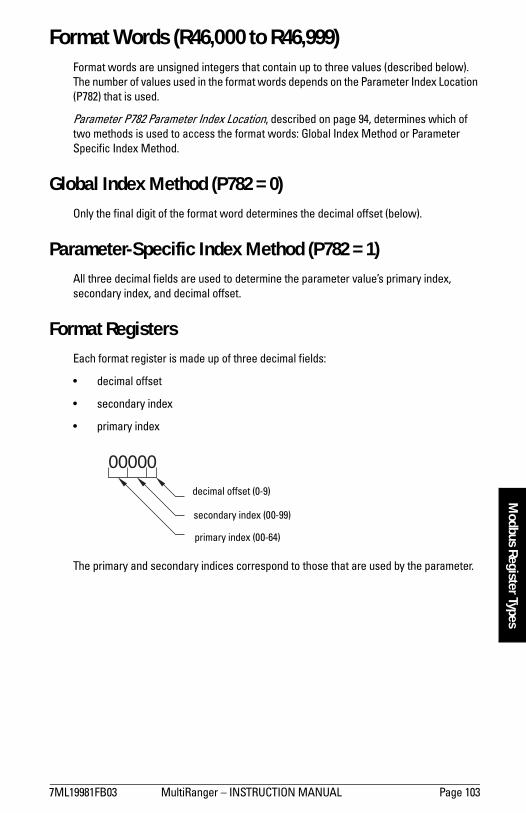
7ML19981FB03 MultiRanger � INSTRUCTION MANUAL Page 103
mm
mm
m
Modbus Register Types
Format Words (R46,000 to R46,999)Format words are unsigned integers that contain up to three values (described below). The number of values used in the format words depends on the Parameter Index Location (P782) that is used.
Parameter P782 Parameter Index Location, described on page 94, determines which of two methods is used to access the format words: Global Index Method or Parameter Specific Index Method.
Global Index Method (P782 = 0)Only the final digit of the format word determines the decimal offset (below).
Parameter-Specific Index Method (P782 = 1)All three decimal fields are used to determine the parameter value�s primary index, secondary index, and decimal offset.
Format RegistersEach format register is made up of three decimal fields:
� decimal offset
� secondary index
� primary index
The primary and secondary indices correspond to those that are used by the parameter.
primary index (00-64)
secondary index (00-99)
decimal offset (0-9)

Page 104 MultiRanger � INSTRUCTION MANUAL 7ML19981FB03
mm
mm
m
Mod
bus
Regi
ster
Typ
esThe decimal offset indicates how the remote system must interpret the integer value that is stored in the parameter access register. The following table shows how different parameter values can be shown based on a register value (integer) of 1234.
Examples of using the format word for both the index values and the decimal offset value are shown below:
To write these values you can use a decimal offset as follows: format word = (primary index x 1000) + (secondary index x 10) + (decimal).
Decimal Offset Example0 0 1,234
1 �1 12,340
2 �2 123,400
3 �3 1,234,000
4 �4 12,340,000
5 �5 123,400,000
6 +1 123.4
7 +2 12.34
8 +3 1.234
9 Percent 12.34%
Format Primary Index Secondary Index Decimal
00000 00 00 0
01003 01 00 3 right
02038 02 03 3 left
05159 05 15 percent

7ML19981FB03 MultiRanger � INSTRUCTION MANUAL Page 105
mm
mm
m
Data Types
Data Types
The MultiRanger parameters do not always use integers to hold values. For the convenience of the programmer, those values are converted to and from a 16-bit integer number. This section describes the conversion process. The sections that follow describe where those values are in the discrete I/O and block transfer addresses, and how to get the parameters you need.
Numeric ValuesNumeric parameter values are the most common. For example, parameter P920 (Reading) returns a number that represents the current reading (either level or volume, depending on the MultiRanger configuration).
Numeric values are requested or set in units or percent of span, and may be specified with a number of decimal places.
Numeric values must be in the range �20,000 to +20,000 to be valid. If a parameter is requested and its value is more than +20,000, the number 32,767 is returned; if it is less than �20,000, the number �32,768 is returned. If this overflow happens, decrease the number of decimal places.
If a parameter cannot be expressed in terms of percent of span, or has no meaningful value, the number 22,222 is returned. Try requesting the parameter in units, or refer to P005 in the Parameter Reference section on page 122.
Bit ValuesBits are packed into registers in groups of 16 bits (1 word). In this manual, the bits are numbered from 1 to 16, with bit 1 as the least significant bit (LSB) and bit 16 as the most significant bit (MSB).
Unsigned Double Precision Integer (UINT32) Large numbers are put into unsigned 32 bit integers. By default, they are set up so that the first word (register) is the most significant word (MSW) and the second word (register) is the least significant word (LSW).
16 15 14 13 12 11 10 09 08 07 06 05 04 03 02 01
MSB LSB

Page 106 MultiRanger � INSTRUCTION MANUAL 7ML19981FB03
mm
mm
m
Data
Typ
esFor example, if R41,442 is read as a UINT32, the 32 bits would look like this:
The two registers are read as a 32-bit integer.
The most significant word (MSW) and least significant word (LSW) can be reversed to accommodate some Modbus drivers. See Word Order (R40,062) on page 96 for details.
The position of the decimal place is dependent on the register. For more details see the description of the register.
Split ValuesCertain parameters are actually a pair of numbers separated by a colon, using this format: xx:yy.
One example is P807, Transducer Noise, where:
xx = the average noise value in dB
yy = the peak noise in dB
The number which corresponds to xx:yy, either for reading or setting a parameter, is determined by the following formula:
For storing to the device:value = (xx + 128) x 256 + (yy + 128)
For reading from the device:xx = (value / 256) � 128yy = (value % 256) � 128
where % is the modulus operator.
The modulus can be computed by following these steps:value1 = value / 256value2 = remainder of value1value3 = value2 x 256yy = value3 � 128
It may simplify Parameter to notice:xx = (most significant byte of value) � 128yy = (least significant byte of value) � 128
R41,442 R41,443
16 MSW 1 16 LSW 1
32 32-bit integer value (UINT32) 1
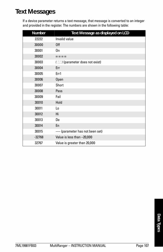
7ML19981FB03 MultiRanger � INSTRUCTION MANUAL Page 107
mm
mm
m
Data Types
Text MessagesIf a device parameter returns a text message, that message is converted to an integer and provided in the register. The numbers are shown in the following table:
Number Text Message as displayed on LCD22222 Invalid value
30000 Off
30001 On
30002 ≡ ≡ ≡ ≡
30003 (parameter does not exist)
30004 Err
30005 Err1
30006 Open
30007 Short
30008 Pass
30009 Fail
30010 Hold
30011 Lo
30012 Hi
30013 De
30014 En
30015 ---- (parameter has not been set)
-32768 Value is less than �20,000
32767 Value is greater than 20,000

Page 108 MultiRanger � INSTRUCTION MANUAL 7ML19981FB03
mm
mm
m
Data
Typ
es
Relay Function Codes (P111 Only) Please note that the MultiRanger 200 offers more function codes.
If a device parameter returns a relay function code, that message is converted to a number and is then provided in the register. The numbers are shown in the following table:
MultiRanger 100
MultiRanger 200
Control Relay Function Code Number P111General OFF, relay not used 0 0
Undesignated Level Alarm 1 1
Low-Low Level Alarm 2 1 � LL
Low Level Alarm 3 1 � L
High Level Alarm 4 1 � H
High-High Level Alarm 5 1 � HH
Loss of Echo (LOE) Alarm 20 6
Transducer Cable Fault Alarm 16 7
Pump Fixed Duty Assist 25 50
Alternate Duty Assist 30 52
Control Communication 66 65
Control Relay Function Code Number P111General OFF, relay not used 0 0
Undesignated Level Alarm 1 1
Low-Low Level Alarm 2 1 � LL
Low Level Alarm 3 1 � L
High Level Alarm 4 1 � H
High-High Level Alarm 5 1 � HH
In Bounds Alarm 6 2
Out of Bounds Alarm 9 3
Rate of Level Change Alarm 12 4
Temperature Alarm 15 5
Loss of Echo (LOE) Alarm 20 6
Transducer Cable Fault Alarm 16 7
Pump Totalizer 22 40
Flow Sampler 23 41
Fixed Duty Assist 25 50
Fixed Duty Backup 26 51
Alternate Duty Assist 30 52

7ML19981FB03 MultiRanger � INSTRUCTION MANUAL Page 109
mm
mm
m
Data Types
See P111 on page 134 of theParameter Reference section.
Pump (con�t)
Alternate Duty Backup 31 53
Service Ratio Duty Assist 35 54
Service Ratio Duty Backup 36 55
First In First Out (FIFO) 40 56
Control Flush Valve 65 64
Communication 66 65
Control Relay Function Code Number P111

Page 110 MultiRanger � INSTRUCTION MANUAL 7ML19981FB03
mm
mm
m
Erro
r Han
dlin
g
Error Handling
Modbus ResponsesWhen polled by a Modbus Master, a slave device will do one of the following:
1. Not reply. This means that something went wrong with the transmission of the message.
2. Echo back the command with the correct response (see the Modbus specification for more details). This is the normal response.
3. Return an Exception Code. This reflects an error in the message.
MultiRanger uses the following exception codes:
Error HandlingErrors can be traced to two general sources:
1. There is an error in transmission.
OR
2. The host tries to do something that is not a valid action.
In the first case, the MultiRanger does not respond and the master waits for a response time out error, which causes the master to re-send the message.
In the second case, the response depends on what the host tries to do. In general, MultiRanger will not give an error to the host request. Various actions and the expected outcome are as follows:
� If the host reads an invalid register, the host will get an undetermined value back.
� If the host writes an invalid register (a non-existing parameter or a read only parameter), the value will be ignored and no error response will be made. However, the current value will not reflect the desired new value.
� If the host writes a read only register, then the value will be ignored and no error response will be made. However, the current value will not reflect the desired new value.
Code Name Meaning01 Illegal Function The function code received in the query is
not an allowable action for the slave.
02 Illegal Data Address The data address received in the query is not an allowable address for the slave.
03 Illegal Data Value A value contained in the query data field is not an allowable value for the slave.

7ML19981FB03 MultiRanger � INSTRUCTION MANUAL Page 111
mm
mm
m
Error Handling
� If P000 is activated, then the value will be ignored and no error response will be made. However, the current value will not reflect the desired new value.
� If the host attempts to write one or more registers that are out of range, an exception response code 2 or 3 is generated, depending if the start address is valid.
� If the host used an unsupported function code, an exception response code of 01 should be generated. However, this is not guaranteed and there may be no response.

Page 112 MultiRanger � INSTRUCTION MANUAL 7ML19981FB03
mm
mm
m
Erro
r Han
dlin
g
Communication Troubleshooting
Generally1. Check the following:
� There is power at the unit� The LCD is showing the relevant data� The device can be programmed using the hand programmer
2. Check the wiring pin outs and verify that the connection is correct.
3. Verify that values in the set-up parameters (P770 to P779) match the settings in the computer used to communicate with the unit.
4. Check that the port on the computer is correct. Sometimes trying a different Modbus driver will solve the problem. An easy stand-alone driver called ModScan32 is available from Win-Tech at www.win-tech.com. This driver is helpful for testing communications.
Specifically1. The MultiRanger is set to communicate via a modem but no communication is
returning to the master.
� Check that the parameters are set up correctly and that the correct port is configured
� Verify the wiring diagram. Note that there is a difference between wiring directly to a computer and wiring to a modem. Verify that the modem is set up correctly. Siemens Milltronics has a series of Application Guides that may help. Please contact your local Siemens Milltronics representative for more information on Application Guides.
2. A MultiRanger parameter is set via remote communications, but the parameter remains unchanged.
� Some parameters can only be changed when the device is not scanning. Try putting the device in program mode, using the operating mode function.
� Try setting the parameter from the keypad. If it can not be set using the keypad, check the lock parameter and set it to 1954.

7ML19981FB03 MultiRanger � INSTRUCTION MANUAL Page 113
mm
mm
m
Comm
unication Appendix A
Communication Appendix A: Single Parameter Access (SPA)
This Appendix is intended to provide someone with advanced communications knowledge the ability to access any parameter value in any available format.
Built into MultiRanger is an advanced handshaking area that can be used to read and write single registers to the MultiRanger. This section performs a similar function to the Parameter access section. The differences are:
1. Advanced section is more powerful and harder to program.
2. Advanced section only gives you access to one parameter at a time.
MappingParameter Read and Write (40,090 � 40,097) is a series of eight registers used for reading and writing parameter values to and from the MultiRanger. The first three registers are always unsigned integers representing parameters and index values. The second five registers are the format and value(s) of the parameter.
All parameters normally accessed through the hand-held programmer are available through these registers.
Reading ParametersTo read parameters through Modbus do the following steps:
1. Send the parameter, its primary index, and its secondary index (usually 0), and format to registers 40,090 to 40,093.
2. Wait until you can read the written values from the registers (40,090 to 40,093) to confirm that the operation is complete.
3. Read the value from registers 40,094 and 40,095.
Address Description40,090 Parameter (integer)
40,091 Primary Index (integer)
40,092 Secondary Index (integer)
40,093 Format word (bit mapped)
40,094 Read value, word 1
40,095 Read value, word 2
40,096 Write value, word 1
40,097 Write value, word 2

Page 114 MultiRanger � INSTRUCTION MANUAL 7ML19981FB03
mm
mm
m
Com
mun
icat
ion
App
endi
x A
Writing ParametersTo set parameters through Modbus do the following steps:
1. Send the parameter, its primary index, and its secondary index (usually 0) to registers 40,090, 40,091, and 40,092.
2. Write the value to registers 40,096 and 40,097.
3. Write the desired format word to register 40,093 to enable the MultiRanger to interpret the value correctly.
Format Register
For example, to format the level reading so that it is shown in percent with two decimal places shifted left, the format bits would look like this:
The value sent to the MultiRanger is 0001001000000000 binary or 512 decimal. The value 512 is sent as an integer to register 40,093 to format the output words 40,094 and 40,095 accordingly.
If the numeric data type is set for integer and the value contains decimal places, they are ignored. In this situation, use the decimal offset to ensure that you have an integer value and then write your code to recognize and handle the decimal offset.
Bits Values Description1-8 0-2 Error Code
9-11 0-7 3-bit number representing decimal offset
12 0/1 direction of offset (0 = right, 1 = left)
13 0/1 Numeric format: Fixed (0) or Float (1)
14 0/1 Read or Write of data, Read (0), Write (1)
15 0/1 Word order: Most Significant Word first (0), Least Significant Word first (1)
16 Reserved
Bit Numbers
16 15 14 13 12 11 10 09 08 07 06 05 04 03 02 01
Bit Values 0 0 0 0 0 0 1 0 0 0 0 0 0 0 0 0
rese
rved
mos
t sig
nific
ant f
irst
read
fixed
form
at
offs
et d
irect
ion
to ri
ght
deci
mal
offs
et o
f 2
no e
rror
cod
e
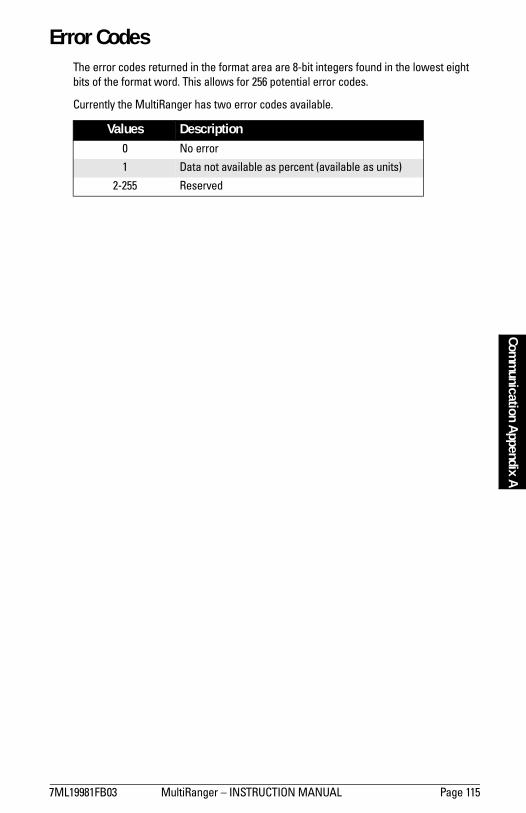
7ML19981FB03 MultiRanger � INSTRUCTION MANUAL Page 115
mm
mm
m
Comm
unication Appendix A
Error CodesThe error codes returned in the format area are 8-bit integers found in the lowest eight bits of the format word. This allows for 256 potential error codes.
Currently the MultiRanger has two error codes available.
Values Description0 No error
1 Data not available as percent (available as units)
2-255 Reserved

Page 116 MultiRanger � INSTRUCTION MANUAL 7ML19981FB03
mm
mm
m
Com
mun
icat
ion
App
endi
x A
Notes

7ML19981FB03 MultiRanger � INSTRUCTION MANUAL Page 117
mm
mm
m
Parameters
Parameter Reference
The MultiRanger is configured through its parameters, and the application determines the parameter values which are entered into the unit.
Please check your value entries carefully before operating the MultiRanger to ensure optimum performance.
MultiRanger 100 and MultiRanger 200All MultiRanger 100 and MultiRanger 200 parameters are listed in this section. MultiRanger 200 parameters are identified separately. The parameter title includes this marking [MR 200], indicating that parameter applies to the MultiRanger 200 only.
As a general rule, parameters affecting volume apply only to the MultiRanger 200.
Helpful HintsPlease note the following:
� Default values are always indicated with an asterix (*)� Global values are common for all inputs and outputs on the unit� Indexed parameters can apply to more than one input or output� Primary index relates to an input or output � Secondary index allows for multiple values on an indexed point
Accessing a Secondary Index
1. Press MODE , and then press DISPLAY to activate secondary index.
The icon appears under the index field.2. Enter the secondary index, and then enter the values to set the secondary index.

Page 118 MultiRanger � INSTRUCTION MANUAL 7ML19981FB03
mm
mm
m
Para
met
ers
Notes
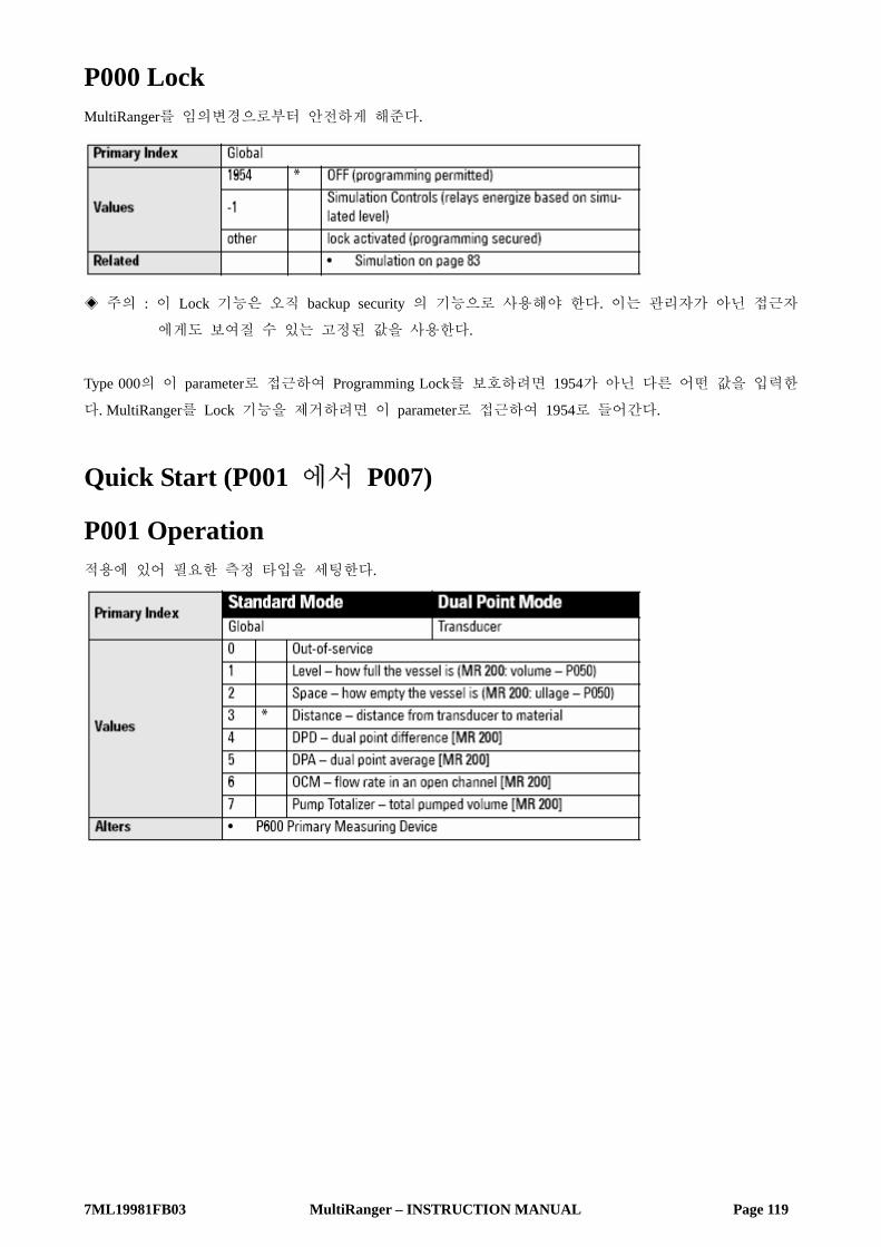
7ML19981FB03 MultiRanger – INSTRUCTION MANUAL Page 119
P000 Lock
MultiRanger를 임의변경으로부터 안전하게 해준다.
◈ 주의 : 이 Lock 기능은 오직 backup security 의 기능으로 사용해야 한다. 이는 관리자가 아닌 접근자
에게도 보여질 수 있는 고정된 값을 사용한다.
Type 000의 이 parameter로 접근하여 Programming Lock를 보호하려면 1954가 아닌 다른 어떤 값을 입력한
다. MultiRanger를 Lock 기능을 제거하려면 이 parameter로 접근하여 1954로 들어간다.
Quick Start (P001 에서 P007)
P001 Operation 적용에 있어 필요한 측정 타입을 세팅한다.

7ML19981FB03 MultiRanger – INSTRUCTION MANUAL Page 120
For DPD and DPA Programming [MR 200] 지금의 특징들은 오직 MultiRanger 200에만 적용이 됨.
Single Point Model 사용시 Dual Point Difference (DPD)나 Dual Point Average (DPA)의 경우에 unit은 같은 종류의 두 개의 transducer가
필요하거나, 하나의 transducer와 하나의 mA input이 필요하다. 만약에 두 개의 transducer가 사용된다면,
모든 transducer parameters는 indexed 되고, 제3의 레벨 지점이 계산이 된다.
• DPD (difference) = Point 1 – Point 2
• DPA (average) = (Point 1 + Point 2)/2. 계산되는 DPD나 DPA는 항상 Point 1과 2에 근거하여 산출된다.
이런 수행에 있어서 세 개의 레벨 포인트 (transducer 1, transducer 2, 혹은 계산된 Point)는 relay의 근원으
로 사용될 수 있다.
Point는 세계적으로 4 혹은 5로 세팅되어야 한다. Point 3은 위에 보여진 바와 같이 계산된다. 페이지 67
의 Rake Control 의 예시를 참고바란다.
Dual Point Model 사용시 DPA 혹은 DPD 기능을 위한 Dual Point MultiRanger 를 세팅하기 위해서는 Point 3은 4나 5로 세팅되어야
만 한다. Point 1과 2는 4나 5로 세팅될 수 없으나, 이런 Points 들은 Point 3에 있어서 값의 산출에 사용된
다.
이 테이블은 사용 적용가능 기능을 보여준다.
P002 Material Material type
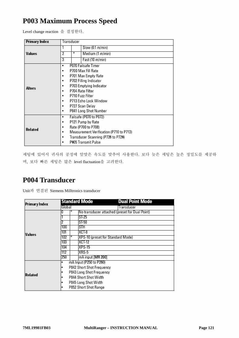
7ML19981FB03 MultiRanger – INSTRUCTION MANUAL Page 121
P003 Maximum Process Speed Level change reaction 을 결정한다.
세팅에 있어서 귀사의 공정에 알맞은 속도를 맞추어 사용한다. 보다 늦은 세팅은 높은 정밀도를 제공하
며, 보다 빠른 세팅은 많은 level fluctuation을 고려한다.
P004 Transducer Unit과 연결된 Siemens Milltronics transducer

7ML19981FB03 MultiRanger – INSTRUCTION MANUAL Page 122
P005 Units 치수의 값에 사용되는 측정 단위
변환 된 이 값들은 자동으로 보여진 많은 parameter에서 단위가 바뀐다. 현재의 값은 변환되며, 재입력은
필요하지 않다.
P006 Empty Transducer의 표면에서 비어있을 시의 Point까지를 P005의 단위에 상응하는 거리를 입력한다.
Span 이 이미 다른 값으로 세팅되어 있지 않다면 이 값들로의 세팅은 Span (P007)을 역시 세팅한다.
Distance operation (P001=3)에서 Span은 Empty로 미리 조정된다.

7ML19981FB03 MultiRanger – INSTRUCTION MANUAL Page 123
P007 Span 측정되기 위한 range level의 세팅
Span 값은 최대로 가능한 값이 미리 조정된다. 최대 적용 range를 반영하는 값을 입력한다.
모든 Siemens Milltronics transducer에 있어서 0.33m가 불감대이므로 transducer 표면의 0.33m 내의 거리를
모니터링 하는 것은 피해야 한다. (불감대 이상의 거리가 필요하다. – Transduecer 매뉴얼을 참고바람)
다른 많은 parameter들은 span의 백분율로써 세팅된다. (단위에 있어 입력이 된다면) 이런 다른 parameter
의 값들은 만약 span이 설치 후 수정된다면 변하게 되며, 다른 parameter들은 empty 레벨에서 transducer
face까지 이상의 정해진 레벨을 사용할 때 측정된다.
MultiRanger 200 모든 볼륨은 span에 근거하므로 만약 볼륨 계산이 필요하다면, 이는 최대의 볼륨 포인트로 세팅되어야
한다.
Volume (P0505 to P055) [MR 200] 볼륨 parameter는 오직 MultiRanger 200에만 적용됨을 알아두어야 한다.
Vessel 이나 wet well volume에 기초한 판독을 보이기 위해 MultiRanger를 가능하게 하려면 이 parameter를
사용한다.
P050 Tank Shape [MR 200] 모니터링 되는 vessel이나 wet well 과 일치하는 Tank Shape 값을 입력한다.
Operation이 Level (P001=1)일 때, 액체 (material) 부피가 계산된다.
Operation이 Space일 때, 남은 vessel 용량이 계산된다. Run mode 시, 판독은 최대 부피의 백분율로 나타내
진다. 부피 단위의 단위를 바꾸려면, Maximum Volume (P051) 을 보기 바란다.

7ML19981FB03 MultiRanger – INSTRUCTION MANUAL Page 124
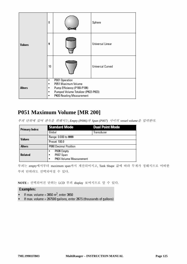
7ML19981FB03 MultiRanger – INSTRUCTION MANUAL Page 125
P051 Maximum Volume [MR 200] 부피 단위에 있어 판독을 위해서는, Empty (P006)과 Span (P007) 사이의 vessel volume을 입력한다.
부피는 empty에서부터 maximum span까지 계산되어지고, Tank Shape 값에 따라 무게가 정해지므로 어떠한
부피 단위라도 선택되어질 수 있다.
NOTE : 선택되어진 단위는 LCD 부피 display 보여지므로 알 수 있다.

7ML19981FB03 MultiRanger – INSTRUCTION MANUAL Page 126
P052 Tank Dimension A [MR 200] P050 Tank Shape 상에서 사용되는 Dimension A
다음의 하나를 선택하여 입력한다.
• P050 = 2,3,4 혹은 5일 경우에 탱크 바닥의 높이
혹은
• P050 = 7, 단위상에서 (P005)일 경우에 탱크의 한쪽 끝 부분의 길이
P053 Tank Dimension L [MR 200] P050 Tank Shape 상에서 사용되는 Dimension L
다음을 입력한다.
• P050 = 7일 경우에 탱크 길이 (양끝 부분은 제외)
P054 Level Breakpoints (Universal Volume Calculation) [MR 200] 미리 설정된 모양보다도 탱크 모양이 너무 복잡하다면 부분에 근거하여 부피에 있어 정확히 할 수 있다.
더 많은 정보는 페이지 117의 Accessing a Secondary Index를 참고 바람.
다음을 입력한다.
• P050 = 9 혹은 10일 경우에 32 level breakpoint 까지 (부피가 알려진 곳)

7ML19981FB03 MultiRanger – INSTRUCTION MANUAL Page 127
Entering a Level Breakpoint 1. parameter P054로 이동한다.
2. 측정 단위에 있어 각각의 index에 breakpoint를 입력한다.
3. 각각의 breakpoint는 P055상의 같은 index와 일치함을 확인한다.
P055 Volume Breakpoints and Characterization
(Universal Volume Calculation) [MR 200] level breakpoints (P055)로 정의된 각각의 부분은 부피를 필요로 하며 이에 MultiRanger는 level에서 volume
계산을 할 수 있다.
전형적인 부피 계산
Entering a Volume Breakpoint 1. parameter P055로 이동한다.
2. 각각의 index에 volume을 입력한다.
3. 각각의 volume은 P054상의 같은 index와 일치함을 확인한다.
Display and Reading (P060 to P062) 이 parameter들은 다음의 사항에 사용된다.
• 보여지는 소수점 자리의 수를 변경
• 판독에 있어 단위의 변경
• Empty (P006) 혹은 Span (P007) 외의 측정의 언급

7ML19981FB03 MultiRanger – INSTRUCTION MANUAL Page 128
P060 Decimal Position LCD 상의 사용되는 소수점 자리의 최대값을 정의한다.
Run mode에서 소수점 자리는 표시되는 허용자리가 초과되는 것을 수정한다. 소수점 자리가 이동되는 것
을 방지하려면 100%에서 보여지는 소수점 자리의 수를 줄여야 한다.
예시 : 100%에서 15m일 경우에, 소수점 두 자리를 사용하면 15.00 혹은 12.15. 의 표시가 나타남
P061 Convert Reading [MR 200] 무게를 고려하기 위해 현재의 값에 특정 양을 곱한다.
• 만약 측정 값이 feet라면, yards의 수를 나타내기 위해 0.3333을 기입한다.
• 간단한 linear 형일 경우에 부피변환 P005를 1 로 맞추고 정확한 변환 값을 얻기 위해서 unit 마다
volume measurement를 기입한다. 예를 들면, 저장고가 수직으로 meter마다 100 리터를 포함한다면, 리터
상에서 판독 값을 얻기 위해서 100을 사용한다.
• 이 방법은 부피 계산을 하지 않는다. 어떠한 특성에 해당되는 volume (펌프 효율성 같은)이 사용된다면
volume parameter에도 불구하고 이는 사용되어지지 않는다. 정확한 실제 volume을 계산하려면 Volume
(P050 에서 P055)를 참고바람
• 최대의 현재 표시 치에 의해 곱해졌을 경우 나타내어질 수 있는 한계를 초과하는 값을 입력하는 것을
피해야 한다. 만약 값이 네 자리를 초과한다면 EEE가 보여진다.
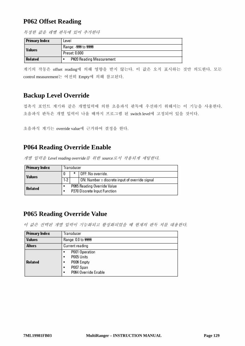
7ML19981FB03 MultiRanger – INSTRUCTION MANUAL Page 129
P062 Offset Reading 특정한 값을 레벨 판독에 있어 추가한다
계기의 작동은 offset reading에 의해 영향을 받지 않는다. 이 값은 오직 표시하는 것만 의도한다. 모든
control measurement는 여전히 Empty에 의해 참고된다.
Backup Level Override 접촉식 포인트 계기와 같은 개별입력에 의한 초음파식 판독에 우선하기 위해서는 이 기능을 사용한다.
초음파식 판독은 개별 입력이 나올 때까지 프로그램 된 switch level에 고정되어 있을 것이다.
초음파식 계기는 override value에 근거하여 결정을 한다.
P064 Reading Override Enable 개별 입력을 Level reading override를 위한 source로서 작용되게 세팅한다.
P065 Reading Override Value 이 값은 선택된 개별 입력이 기능화되고 활성화되었을 때 현재의 판독 치를 대용한다.
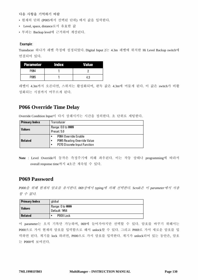
7ML19981FB03 MultiRanger – INSTRUCTION MANUAL Page 130
다음 사항을 기억하기 바람
• 현재의 단위 (P005에서 선택된 단위) 에서 값을 입력한다.
• Level, space, distance로서 유효한 값
• 부피는 Backup level에 근거하여 계산된다.
Transducer 하나가 레벨 측정에 설정되었다. Digital Input 2는 4.3m 레벨에 위치한 Hi Level Backup switch에
연결되어 있다.
레벨이 4.3m까지 오른다면, 스위치는 활성화되며, 판독 값은 4.3m에 머물게 된다. 이 값은 switch가 비활
성화되는 시점까지 머무르게 된다.
P066 Override Time Delay Override Condition Input이 다시 상쇄시키는 시간을 정의한다. 초 단위로 세팅한다.
Note : Level Override의 동작은 측정주기에 의해 좌우된다. 이는 작동 상태나 programming에 따라서
overall response time까지 4초간 계속될 수 있다.
P069 Password P000을 위해 현재의 암호를 유지한다. 069상에서 typing에 의해 선택한다. Scroll은 이 parameter에서 사용
할 수 없다.
이 parameter는 오직 기록만 가능하며, 069에 들어가야지만 선택할 수 있다. 암호를 바꾸기 위해서는
P000으로 가서 현재의 암호를 입력함으로 해서 unlock할 수 있다. 그리고 P069로 가서 새로운 암호를 입
력하면 된다. 계기를 lock 하려면, P000으로 가서 암호를 입력한다. 계기가 unlock되어 있는 동안은, 암호
는 P000에 보여진다.

7ML19981FB03 MultiRanger – INSTRUCTION MANUAL Page 131
Failsafe (P070 to P072)
P070 Failsafe Timer Failsafe State이 활성화되기 전의 효력이 없는 measurement가 경과되기 위한 시간
일단 활성화되면, Failsafe State은 다음을 시작하게 된다
1. Material Level은 P071의 Failsafe Material Level에 근거하여 기록된다.
• Unit은 Program된 바대로 새로운 Level에 응답한다. (프로그래밍 된 control과 alarm relay가 활성화)
• 개별적인 relay는 failsafe response와는 독립적일 수 있다. P129 Relay Failsafe를 참고.
2. 타당한 error는 보여지게 된다.
• LOE : transducer로부터의 echo의 손실
• Short : 짧은 transducer cable
• Open : 단절된 transducer cable
• Error : 다른 모든 문제점
미리 설정 된 값들을 수정할 때, 공정을 보호하기 위해 최대한 짧게 설정해야 하며, false alarm을 피하기
위해 충분히 길게 한다. 테스트를 위해서는 No Delay (0.0 Minutes) 만을 사용해야 한다.
P071 Failsafe Material Level Failsafe State이 시작되면 material level이 기록된다.
Failsafe operation 동안에 필요한 relay operation에 근거한 Failsafe Material Level을 선택한다.

7ML19981FB03 MultiRanger – INSTRUCTION MANUAL Page 132
HI, LO 또는 HOLd의 선택 1. Auxiliary Function symbol을 보여지게 하려면 FUNCTION 버튼을 누른다.
2. 원하는 OPTION을 Scroll하려면 ARROW 버튼을 누른다.
3. 값을 세팅하려면 ENTER를 누른다.
Entering a Measurement Units (P005)에서 Span (P007)의 -50에서 150% 내의 특정한 Failsafe Material Level을 입력하기 위한 것.
Relay reaction Relay Programming이 P129 Relay Failsafe에 영향을 받는 failsafe level에 작용하는 방법
• Alarm relay는 P129 설정을 갖는다 = OFF. 그러므로 Failsafe Material Level에 작용한다.
• Control relay는 P129 설정을 갖는다 = dE. 그러므로 unit이 Failsafe Material Level에 관계없이 Failsafe에
입력될 때 relay에 전압이 끊어진다.
P072 Failsafe Level Advance Speed를 미리 세팅하고 Failsafe Material Level로부터 되돌아온다.
Relays (P100 to P119) MultiRanger는 Control device 그리고 alarm에 사용되는 3개 또는 6 relay (또는 디지털 출력)를 가지고 있다.
계기의 수가 relay에 의해 한정될 때, 모든 control 기능들은 소프트웨어에 의해 접근되어지며 각각의
parameter는 3 혹은 6개의 relay로 index 된다. Relay 부분을 참고 바란다.
Preset Applications (P100) MultiRanger는 광범위한 미리 설정된 리스트를 제공함으로써 보다 쉬운 표준 application을 만든다.

7ML19981FB03 MultiRanger – INSTRUCTION MANUAL Page 133
Control Functions (P111) 각각의 Relay는 MultiRanger의 진보된 특성과 융통성으로 인해 독립적으로 설정될 수 있다. 미리 설정된
적용으로 시작할 수 있으며, 보다 효율적인 적용을 위해서 요구되는 parameter를 변환할 수 있다.
Setpoints (P112, P113) 각각의 Relay는 하나 혹은 보다 많은 setpoints에 의해 동작하게 된다. Setpoints는 absolute level (P112, P113)
혹은 rate of change (P702, P703)에 근거할 수 있다. 각각의 control 기능은 어떤 setpoints가 요구되는지를
기술한다.
P100 Preset Applications [MR 200] Unit을 테스트하거나 설정하기 위한 미리 입력된 6개의 적용사항.
귀사와 비슷하고, 요구되는 parameter를 변화시키는 적용을 선택한다. 만약 알맞지 않다면 페이지 134의
Relay Control Fuction 부분을 참고하기 바란다.
Note : Programming Relay는 흔히 사용되는 범용적인 방법이다.

7ML19981FB03 MultiRanger – INSTRUCTION MANUAL Page 134
P110 Level Source Indexed relay가 measurement point에 할당된 level source를 세팅한다.
Difference와 Average 세팅은 MultiRanger 200의 특성이다.
MultiRanger 200 이의 특성은 오직 MultiRanger 200에만 적용이 가능하다.
In Single Point Mode (Standard) : Point 2와 3은 Operation이 difference 혹은 average로 세팅되었을 경우에만 적용된다.
In Dual Point Mode (Optional) : Point 2는 항상 적용이 가능하며, Point 3은 Operation이 difference 혹은 average로 세팅되었을 경우에만 적
용된다.
P111 Relay Control Function Relay를 trip 하는데 사용되는 control algorithm을 세팅한다.
Parameter P111 값은 MultiRanger 100과 MultiRanger 200 사이에서 일정하지 않다.
indexed relay의 control 기능을 제거하려면 zero 0 (preset) 을 사용한다.
Note : 모든 relay ON/OFF point는 Operation Mode selection (P001)에 상관없이 Empty (P006)으로부터 참고되
어져야 한다.

7ML19981FB03 MultiRanger – INSTRUCTION MANUAL Page 135
MultiRanger 100
1. Parameter가 Modbus 또는 SmartLinx communications를 통해서 읽혀지고 세팅되어질 때, parameter 값은
다른 수로 조사된다. 페이지 87의 Modbus 정보 또는 SmartLinx Manual을 위한 MultiRanger
Communications 부분을 참고하기 바란다.
MultiRanger 200

7ML19981FB03 MultiRanger – INSTRUCTION MANUAL Page 136
1. Parameter가 Modbus 또는 SmartLinx communications를 통해서 읽혀지고 세팅되어질 때, parameter 값은
다른 수로 조사된다. 페이지 87의 Modbus 정보 또는 SmartLinx Manual을 위한 MultiRanger
Communications 부분을 참고하기 바란다.
P112 Relay ON Setpoint Relay가 이것의 NORMAL state으로부터 변하는 Process Point를 세팅한다.
대개의 적용에 있어 relay는 이 point에서 동작하게 된다. IN-BOUNDS 와 OUT-OF-BOUNDS alarm에서, 특
정 범위에서 high point이다. 이 parameter는 다른 지시, 가령 부피 같은, 가 LCD 상에 보여질 때에도
Span (P007)에 따라서 세팅된다.
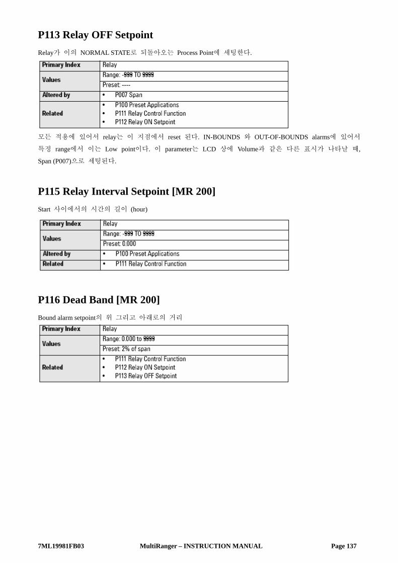
7ML19981FB03 MultiRanger – INSTRUCTION MANUAL Page 137
P113 Relay OFF Setpoint Relay가 이의 NORMAL STATE로 되돌아오는 Process Point에 세팅한다.
모든 적용에 있어서 relay는 이 지점에서 reset 된다. IN-BOUNDS 와 OUT-OF-BOUNDS alarms에 있어서
특정 range에서 이는 Low point이다. 이 parameter는 LCD 상에 Volume과 같은 다른 표시가 나타날 때,
Span (P007)으로 세팅된다.
P115 Relay Interval Setpoint [MR 200] Start 사이에서의 시간의 길이 (hour)
P116 Dead Band [MR 200] Bound alarm setpoint의 위 그리고 아래로의 거리
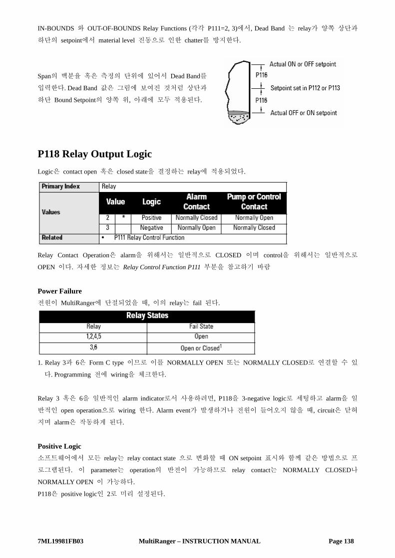
7ML19981FB03 MultiRanger – INSTRUCTION MANUAL Page 138
IN-BOUNDS 와 OUT-OF-BOUNDS Relay Functions (각각 P111=2, 3)에서, Dead Band 는 relay가 양쪽 상단과
하단의 setpoint에서 material level 진동으로 인한 chatter를 방지한다.
Span의 백분율 혹은 측정의 단위에 있어서 Dead Band를
입력한다. Dead Band 값은 그림에 보여진 것처럼 상단과
하단 Bound Setpoint의 양쪽 위, 아래에 모두 적용된다.
P118 Relay Output Logic Logic은 contact open 혹은 closed state을 결정하는 relay에 적용되었다.
Relay Contact Operation은 alarm을 위해서는 일반적으로 CLOSED 이며 control을 위해서는 일반적으로
OPEN 이다. 자세한 정보는 Relay Control Function P111 부분을 참고하기 바람
Power Failure 전원이 MultiRanger에 단절되었을 때, 이의 relay는 fail 된다.
1. Relay 3과 6은 Form C type 이므로 이를 NORMALLY OPEN 또는 NORMALLY CLOSED로 연결할 수 있
다. Programming 전에 wiring을 체크한다.
Relay 3 혹은 6을 일반적인 alarm indicator로서 사용하려면, P118을 3-negative logic로 세팅하고 alarm을 일
반적인 open operation으로 wiring 한다. Alarm event가 발생하거나 전원이 들어오지 않을 때, circuit은 닫혀
지며 alarm은 작동하게 된다.
Positive Logic 소프트웨어에서 모든 relay는 relay contact state 으로 변화할 때 ON setpoint 표시와 함께 같은 방법으로 프
로그램된다. 이 parameter는 operation의 반전이 가능하므로 relay contact는 NORMALLY CLOSED나
NORMALLY OPEN 이 가능하다.
P118은 positive logic인 2로 미리 설정된다.

7ML19981FB03 MultiRanger – INSTRUCTION MANUAL Page 139
Negative Logic P118=3 (negative logic)일 경우에, indexed relay 를 위한 operation은 normal에서 반전된다.
P119 Relay Logic Test Relay control logic을 ACTIVATED 혹은 DE-ACTIVATED state으로 강제시킨다.
이 parameter는 site wiring과 control logic programming을 테스트한다. Relay를 activated 혹은 de-activated 상
태로 강제하는 것은 MultiRanger가 이것에 event나 responding하는 것을 검출하는 것과 비슷하다. 이는 새
로운 설치 시와 control problem을 진단할 때에 매우 유용하다.
Pump Setpoint Modifiers (P121 and P122) [MR 200] 이 parameter들은 오직 MultiRanger 200 에만 적용됨을 기억하기 바람.
이 parameter들은 Pump Group에서 Pump를 시작하게 하는 대체의 방법을 제공한다. Pump control algorithms
의 서술에 대해서는 페이지 56의 Pump Control 부분을 참고바람.
P121 Pump by Rate [MR 200] First ON setpoint가 도달했을 때 pump relay가 rate of level change에 의한 control이 받아들여지도록 세팅한
다.
Multiple pump가 setpoint보다도 rate of level change에 의해 control될 때, 이 기능을 사용한다.
Pump Start 사이의 지연은 P132 Pump Start Delay에 의해 세팅한다.
이는 Pump Control (P111=50 에서 56)을 세팅하는 relay에만 적용한다.

7ML19981FB03 MultiRanger – INSTRUCTION MANUAL Page 140
Note :
• 모든 Pump control relay ON 과 OFF setpoints는 받드시 같은 값이어야 한다.
• 레벨이 OFF setpoint Span (P007)의 5% 이내이면 다음의 Pump 는 시작되지 않는다.
P122 Pump Service Ratio [MR 200] 마지막에 사용된 것보다 Run time ratio에 근거한 Pump 사용을 선택한다.
이 parameter는 오직 P111=54 혹은 55와 함께 relay에 관계한다.
이 parameter를 유용하게 사용하려면, 이를 모든 Pump relay에 할당한다. 각각의 pump relay에 할당된 숫자
는 start 혹은 stop 을 하기 위해 next pump 결정에 적용된 ratio을 나타낸다.
Note : • MultiRanger는 ratio가 true로 유지되는 것을 확인하기 위해 다른 Pumping strategy를 버리지 않을 것이다.
• Pump relay가 같은 값으로 세팅되었다면 ratio는 1:1로 같고 모든 Pump는 동일하게 사용된다.
Independent Relay Failsafe (P129)
P129 Relay Failsafe Relay 마다 failsafe operation을 보다 많은 범용적인 Programming을 허용하기 위해 세팅한다.
Failsafe Material Level (P070)에 영향을 받지 않는 Operation을 위해 이를 사용한다.

7ML19981FB03 MultiRanger – INSTRUCTION MANUAL Page 141
Relay Failsafe는 오직 다음의 relay function (P111)에 적용될 수 있으며 다른 relay control function 기능에는
사용되지 않는다.
Independent Relay Failsafe 값을 선택하려면 :
1. Auxiliary Function symbol을 나타내려면 FUNCTION 버튼을 누른다.
2. Failsafe option을 통해서 scroll 하려면 ARROW 버튼을 누른다.
3. Option을 선택하고 ENTER 를 누른다.
Advanced Pump Control Modifiers (P130 to P137) [MR 200] 이 parameter들은 오직 MultiRanger 200에만 적용됨을 알아두기 바람.
이 parameter들은 오직 pump operation (P111 = 50 에서 56)을 하기 위한 relays set 에만 영향을 미친다.
P130 Pump Run-On Interval [MR 200] Pump run-on occurrences 사이의 시간의 수를 세팅한다.
Pump-down wet well 에서 침전물을 깨끗이 하려면, normal OFF setpoint가 약간의 고체 물질을 뚫고 지나가
기 위해 다다른 후에 pump를 run 시킨다. 이 parameter는 이러한 event 사이에서 time을 세팅한다. 오직
Last pump 작동에서만 계속될 수 있다.
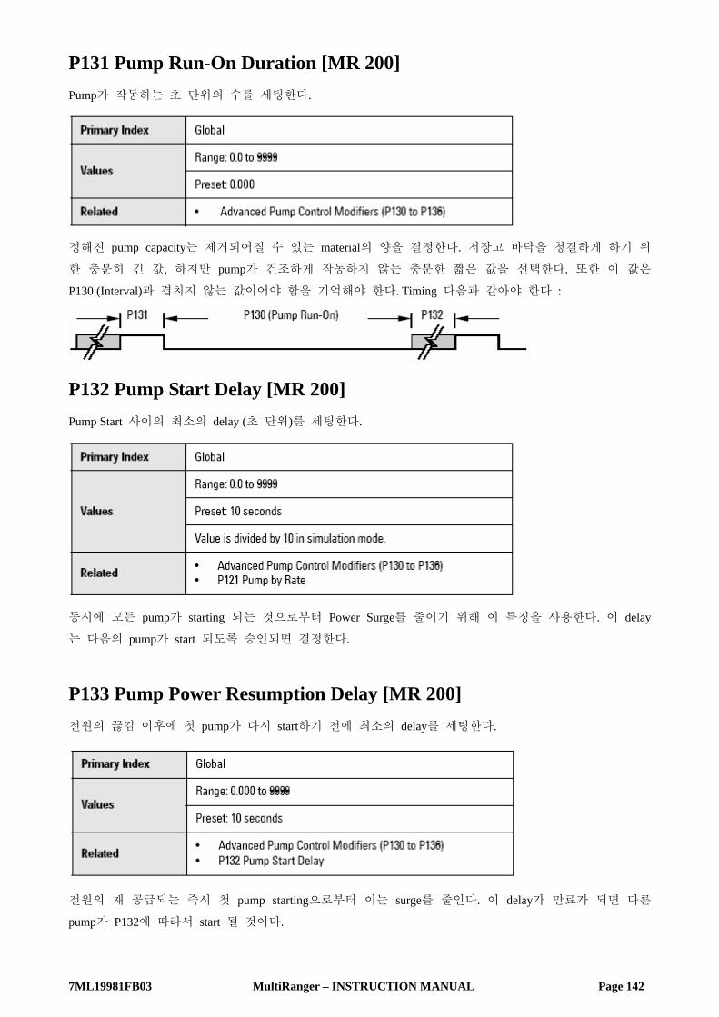
7ML19981FB03 MultiRanger – INSTRUCTION MANUAL Page 142
P131 Pump Run-On Duration [MR 200] Pump가 작동하는 초 단위의 수를 세팅한다.
정해진 pump capacity는 제거되어질 수 있는 material의 양을 결정한다. 저장고 바닥을 청결하게 하기 위
한 충분히 긴 값, 하지만 pump가 건조하게 작동하지 않는 충분한 짧은 값을 선택한다. 또한 이 값은
P130 (Interval)과 겹치지 않는 값이어야 함을 기억해야 한다. Timing 다음과 같아야 한다 :
P132 Pump Start Delay [MR 200] Pump Start 사이의 최소의 delay (초 단위)를 세팅한다.
동시에 모든 pump가 starting 되는 것으로부터 Power Surge를 줄이기 위해 이 특징을 사용한다. 이 delay
는 다음의 pump가 start 되도록 승인되면 결정한다.
P133 Pump Power Resumption Delay [MR 200] 전원의 끊김 이후에 첫 pump가 다시 start하기 전에 최소의 delay를 세팅한다.
전원의 재 공급되는 즉시 첫 pump starting으로부터 이는 surge를 줄인다. 이 delay가 만료가 되면 다른
pump가 P132에 따라서 start 될 것이다.

7ML19981FB03 MultiRanger – INSTRUCTION MANUAL Page 143
P136 Wall Cling Reduction [MR 200] 벽에 있어 material buildup을 줄이기 위한 상단과 하단 setpoint를 다양화한다.
이 값은 setpoint가 백분율이나 또는 단위로부터 편차를 허용하게 되는 범위이다. Relay Setpoints ON 과
OFF 값은 material level이 어떤 같은 지점에서 연속적으로 stop 하지 않는 것을 확실하게 하는 내부의
range가 임의로 변화된다.
P137 Pump Group [MR 200] 하나의 transducer 상에 multiple pump rotation을 위해서 pump를 group에 둔다.
이 특성은 pump (relay points 1-6)을 group 1 혹은 2로 나눈다. 이는 Pump rotation에 적용이 되며 각각의 그
룹 내에서 독립적으로 작용한다.

7ML19981FB03 MultiRanger – INSTRUCTION MANUAL Page 144
Flush Systems (P170 to P173) [MR 200] 이 parameter는 MultiRanger 200에만 적용됨을 알아두기 바람.
이 특성은 pump output back을 침전물을 뒤섞기 위한 wet well 로 변환하는 pump 상에서 전자적으로 작동
되는 flush valve를 control하기 위해 사용된다.
• 다음의 parameter가 0으로 세팅되어 있다면, 이 기능은 작동을 하지 않을 것이다.
• Dual Point mode에서 flush valve는 3개의 적용가능 level input을 위해 세팅할 수 있다.
Standard Mode Flush valve와 함께 pump의 EnviroRanger relay number를 입력한다. 이 pump relay의 작동은 flush system의
사용을 수반한다. 두 P172 Flush Interval과 P171 Flush Cycle은 이 relay의 작동에 근거하며, P111=64로 세팅
된 Flush Valve를 control 한다.
Dual Point Mode Indexed relay는 flush device를 control한다. 이 값은 flush system에 의해 감시된다. Pump relay 값을 flush
relay index 상의 parameter에 입력한다.
Example Relay Two 상에서 flush valve를 control하기 위한 pump Relay One의 감시가 필요하다면, P170[2]=1로 세팅해
야 한다.
P170 Flush Pump [MR 200] Flushing Device를 작용하게 하는 Pump relay의 수를 선택한다.
Flush valve와 함께 pump의 MultiRanger relay number를 입력한다. 이 pump relay의 작동은 flush system의 사
용을 수반한다. 두 P172 Flush Interval [MR 200]과 P171 Flush Cycle [MR 200]은 이 relay의 작동에 근거하며,
P111=64로 세팅된 Flush Valve를 control 한다.
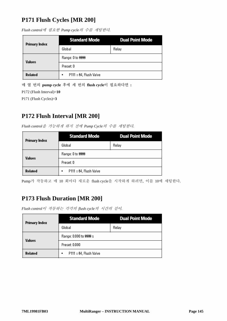
7ML19981FB03 MultiRanger – INSTRUCTION MANUAL Page 145
P171 Flush Cycles [MR 200] Flush control에 필요한 Pump cycle의 수를 세팅한다.
매 열 번의 pump cycle 후에 세 번의 flush cycle이 필요하다면 :
P172 (Flush Interval)=10
P171 (Flush Cycles)=3
P172 Flush Interval [MR 200] Flush control을 가능하게 하지 전에 Pump Cycle의 수를 세팅한다.
Pump가 작동하고 매 10 회마다 새로운 flush cycle을 시작하게 하려면, 이를 10에 세팅한다.
P173 Flush Duration [MR 200] Flush control이 작동하는 각각의 flush cycle의 시간의 길이.

7ML19981FB03 MultiRanger – INSTRUCTION MANUAL Page 146
mA Output (P200 to P219)
P200 mA Output Range mA output 범위를 결정한다.
1 혹은 2가 선택되었다면, mA output은 직접적으로 mA 기능과 비례한다. 만약 3 혹은 4가 선택되었다면
output은 반비례하게 된다.
P201 mA Output Function mA Output/measurement 관계를 수정한다.
P201 parameter의 값은 MultiRanger 100과 MultiRnager 200에서 다양함을 기억하기 바람.
MultiRanger 100

7ML19981FB03 MultiRanger – INSTRUCTION MANUAL Page 147
MultiRanger 200
P202 mA Output Allocation mA output이 계산되어지는 input source를 세팅한다.
P202 parameter의 값은 MultiRanger 100과 MultiRnager 200에서 다양함을 기억하기 바람.
MultiRanger 100
MultiRanger 200
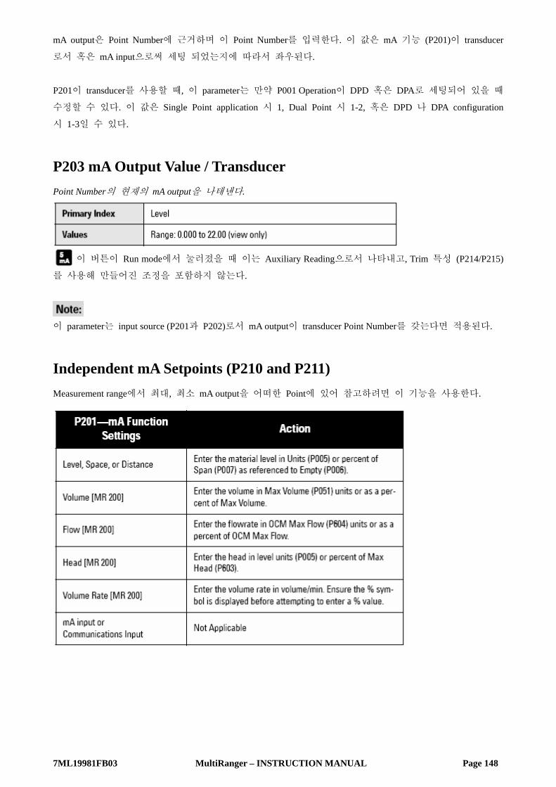
7ML19981FB03 MultiRanger – INSTRUCTION MANUAL Page 148
mA output은 Point Number에 근거하며 이 Point Number를 입력한다. 이 값은 mA 기능 (P201)이 transducer
로서 혹은 mA input으로써 세팅 되었는지에 따라서 좌우된다.
P201이 transducer를 사용할 때, 이 parameter는 만약 P001 Operation이 DPD 혹은 DPA로 세팅되어 있을 때
수정할 수 있다. 이 값은 Single Point application 시 1, Dual Point 시 1-2, 혹은 DPD 나 DPA configuration
시 1-3일 수 있다.
P203 mA Output Value / Transducer Point Number의 현재의 mA output을 나태낸다.
이 버튼이 Run mode에서 눌러졌을 때 이는 Auxiliary Reading으로서 나타내고, Trim 특성 (P214/P215)
를 사용해 만들어진 조정을 포함하지 않는다.
이 parameter는 input source (P201과 P202)로서 mA output이 transducer Point Number를 갖는다면 적용된다.
Independent mA Setpoints (P210 and P211) Measurement range에서 최대, 최소 mA output을 어떠한 Point에 있어 참고하려면 이 기능을 사용한다.

7ML19981FB03 MultiRanger – INSTRUCTION MANUAL Page 149
P210 0/4 mA Output Setpoint Process level과 상응하는 0 또는 4mA 값으로 세팅한다.
0 또는 4mA에 상응하는 값 (unit이나 %에서 적용하는) 값을 입력한다.
P211 20mA Output Setpoint 20mA 값에 상응하는 Process level 값을 세팅한다.
20mA에 상응하는 값 (unit이나 %에서 적용하는) 값을 입력한다.
mA Output Limits (P212 and P213) External device의 input limit 요구에 알맞게 설정해야만 하는 최대, 최소 mA output 값을 조정할 때에 이
기능을 사용한다.
P212 mA Output Min Limit 산출되는 최소의 mA output 값 (mA)을 세팅한다.
Preset은 mA Function (P200)에 의해 결정된다. P200=1 또는 3일 경우, preset은 0.0 이고, P200=2 혹은 4일
경우, preset은 3.8 이다. 이 parameter는 최소 limit이 음의 값을 가질 수 없으므로 영향을 받지 않으며 최
소 current는 항상 0.0 mA가 된다.

7ML19981FB03 MultiRanger – INSTRUCTION MANUAL Page 150
P213 mA Output Max Limit 산출되는 최대의 mA output 값 (mA)을 세팅한다.
mA Output Trim (P214 to P215) 이는 P203 값에 보여진 것처럼 영향을 주지 않으며, 외부계기의 recalibration이 비효율적일 때 사용된다.
P214 4mA Output Trim 4mA output 을 Calibration 한다.
P214가 입력되어질 때 이 값이 수정되어 계기는 4.000 mA를 나타내게 된다.
P215 20mA Output Trim 20mA output 을 Calibration 한다.
P215가 입력되어질 때 이 값이 수정되어 계기는 20.00 mA를 나타내게 된다.
mA Output Failsafe (P219) [MR 200] 이 parameter는 오직 MultiRanger 200에 적용됨을 기억하기 바람.

7ML19981FB03 MultiRanger – INSTRUCTION MANUAL Page 151
P219 mA Output Failsafe [MR 200] Failsafe Material Level (P071)에 영향을 받지 않는 failsafe operation의 사용을 위해 사용한다.
개별적인 mA Failsafe option의 선택 :
1. Auxiliary Function symbol을 나타내기 위해 MODE 버튼을 누른다.
2. Failsafe Option을 제어할 수 있도록 ARROWS 버튼을 누린다.
3. 원하는 Option을 나타났을 때 ENTER 버튼을 누른다.
혹은, 어떤 특정한 값에서 mA output을 산출하려면 필요로 하는 값을 입력한다. 이는 mA output이
transducer (P201=1에서7)에 할당되었을 때만이 사용될 수 있다.
mA Input (P250 to P260) [MR 200] 이 parameter는 MultiRanger 200에만 적용됨을 기억하기 바람.
P250 mA Input Range [MR 200] 연결된 mA 계기의 mA input range를 보여준다.
이는 외부 계기의 출력 범위와 일치하는 range 임을 확인한다. 모든 레벨 측정치는 Span의 %와 mA
range의 %가 같을 것이다.
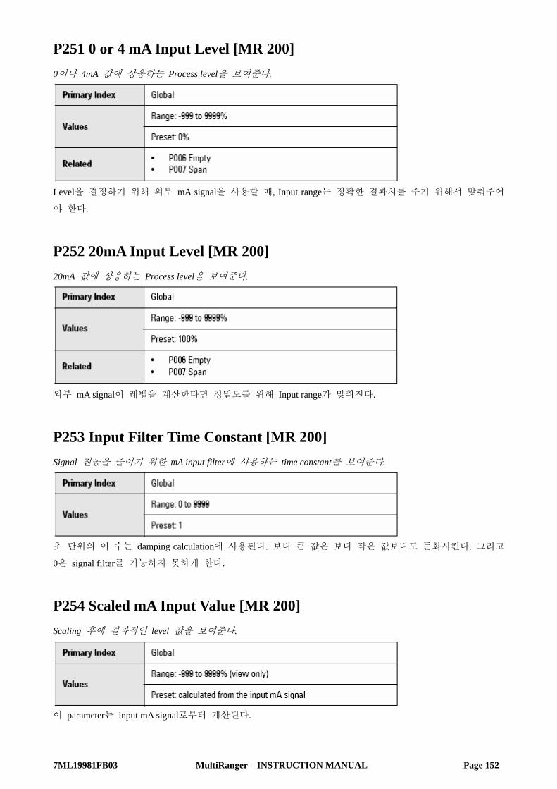
7ML19981FB03 MultiRanger – INSTRUCTION MANUAL Page 152
P251 0 or 4 mA Input Level [MR 200] 0이나 4mA 값에 상응하는 Process level을 보여준다.
Level을 결정하기 위해 외부 mA signal을 사용할 때, Input range는 정확한 결과치를 주기 위해서 맞춰주어
야 한다.
P252 20mA Input Level [MR 200] 20mA 값에 상응하는 Process level을 보여준다.
외부 mA signal이 레벨을 계산한다면 정밀도를 위해 Input range가 맞춰진다.
P253 Input Filter Time Constant [MR 200] Signal 진동을 줄이기 위한 mA input filter에 사용하는 time constant를 보여준다.
초 단위의 이 수는 damping calculation에 사용된다. 보다 큰 값은 보다 작은 값보다도 둔화시킨다. 그리고
0은 signal filter를 기능하지 못하게 한다.
P254 Scaled mA Input Value [MR 200] Scaling 후에 결과적인 level 값을 보여준다.
이 parameter는 input mA signal로부터 계산된다.

7ML19981FB03 MultiRanger – INSTRUCTION MANUAL Page 153
P260 mA Raw Input [MR 200] 외부 계기에 의해 제공되어지는 raw mA input이 보여진다.
Discrete Input Functions (P270 to P275) Discrete input은 다음에 있어 사용될 수 있다 :
• 다른 정보가 communications을 통해서 remote system으로 전달될 때
• Backup level override 시
위쪽에 나열된 parameter를 discrete input이 unit의 operation을 보정하도록 하기 위해 사용한다.
다음의 parameter는 discrete input 자체를 설정하기 위해 사용한다.
Discrete input을 이의 operation을 수정하하는 방법을 포함한 페이지 56의 MultiRanger의 pump control
algorithms을 위한 Pump Control부분을 참고하기 바람.
P270 Discrete Input Function MultiRanger에 의해서 discrete signal이 해석되는 방법을 세팅한다.

7ML19981FB03 MultiRanger – INSTRUCTION MANUAL Page 154
P275 Scaled Discrete Input Value 어떠한 scaling 이 적용된 후에 개별적인 input의 현재의 값이 보여진다.
Program mode에서도 Reading은 연속적으로 업데이트 된다. 이 값은 level override event를 표시한다.
Standard Data Logging (P300 to P321) 모든 records는 CLEAR 버튼을 누름으로 reset 될 수 있다.
Record Temperatures (P300 to P303) 이 특성들은 ℃ 로서 high and/or low 온도를 표시한다. TS-3 온도 센서와 관련되는 parameter가 접근될 때
Point Type display는 TS-3 symbol로 바뀐다.
Unit에 온도센서가 연결되는 것 없이 전원이 연결된다면, -50℃의 값이 보여진다. 이 정보는 설치나 외부
온도 센서의 문제를 추적하는 것에 도움을 줄 수 있다.
P300 Temperature, Transducer Maximum Transducer의 온도 센서에 의해 측정됨에 따라, 연결된 highest temperature 가 보인다.
Transducer wiring 상에서 단락 후에 log를 reset 하기 위해서 CLEAR 버튼을 누른다.

7ML19981FB03 MultiRanger – INSTRUCTION MANUAL Page 155
P301 Temperature, Transducer Minimum Transducer의 온도 센서에 의해 측정됨에 따라, 연결된 lowest temperature 가 보인다.
Transducer wiring 상에서 Open circuit 후에 log를 reset 하기 위해서 CLEAR 버튼을 누른다.
P302 Temperature, Sensor Maximum TS-3 온도센서에 의해 측정됨에 따라, 연결된 highest temperature 가 보여진다.
Transducer wiring 상에서 short circuit 후에 log를 reset 하기 위해서 CLEAR 버튼을 누른다.
P303 Temperature, Sensor Minimum TS-3 온도센서에 의해 측정됨에 따라, 연결된 lowest temperature 가 보여진다.
Transducer wiring 상에서 open circuit 후에 log를 reset 하기 위해서 CLEAR 버튼을 누른다.

7ML19981FB03 MultiRanger – INSTRUCTION MANUAL Page 156
Record Readings (P304 and P305) 이는 high 와 low level 판독치의 record의 현상을 확인한다. 설치가 올바르게 행해졌다면 이 값을 reset 하
기 위해서 CLEAR 버튼을 누른다.
P304 Reading Max 계산된 highest Reading 값을 보여준다. (표준 판독 단위 혹은 %)
P305 Reading Min 계산된 lowest Reading 값을 보여준다. (표준 판독 단위 혹은 %)
Pump Records (P310 to P312) 관계된 Relay Function (P111)이 pump control feature를 위해 세팅이 되어 있다면 이는 pump usage를 확인하
기 위한 특징을 지닌다. 이 값은 관계된 terminal에 연결된 pump의 값이다.
현재의 값을 그 값으로 세팅하기 위해 값을 입력한다. Pump에 log된 시간의 알려진 number에 추가된다면
이를 사용한다. 혹은 이 값은 유지관리 후에 zero 0으로 reset될 수 있다.
P309 Pump RUN Time Relay가 마지막으로 activate 된 이래로 분단위로의 누적된 시간을 표시한다.
Parameter는 펌프가 얼마나 길게 운행되는가가 결정되는 것이 단정된 이래로 시간의 길이를 측정한다.
선택적으로, 이것은 alarm 상태에서 얼마나 긴지를 보여주기 위해서 relay를 모니터링 할 수 있다. 이는
relay가 작동될 때마다 reset 된다.

7ML19981FB03 MultiRanger – INSTRUCTION MANUAL Page 157
P310 Pump Hours 나타나는 Relay Number를 위한 축적되는 ON time을 보여주거나 reset 한다.
값은 부동 소수점 자리로 보여진다. (소수점 전으로 많은 자리가 보여질수록 뒤로는 보다 적게 된다.)
가 Run mode에서 눌러졌을 때 이 값은 보여진다.
P311 Pump Starts Relay Number 가 ON 하는 누적된 times 의 수가 보여지거나 reset 된다.
이 값은 버튼이 눌러지고 Run mode에서 5초 동안 머물러지면 보여진다.
P312 Pump Run Ons [MR 200] 보여지는 Relay Number가 Run On Interval을 경유하여 ON으로 머무는 누적된 times의 수가 보여지고 reset
된다.
이 parameter는 오직 MultiRanger 200에만 적용됨을 기억바람.
Flow Records (P320 and P321) [MR 200] 이 parameter는 오직 MultiRanger 200에만 적용됨을 기억바람.
이 기능은 Operation이 OCM (P001=6)으로 세팅되거나 OCM 계기가 정해지면 (P600≠0) 사용할 수 있다.
OCM Max Flow (P604) unit이나 OCM Max Flow % 상에서 보여지는 Record high and low flow rates 현상을 확
인하기 위하여 이를 사용한다.
설치작업이 알맞게 되었을 때 reset을 하기 위해서 CLEAR 버튼을 누른다.
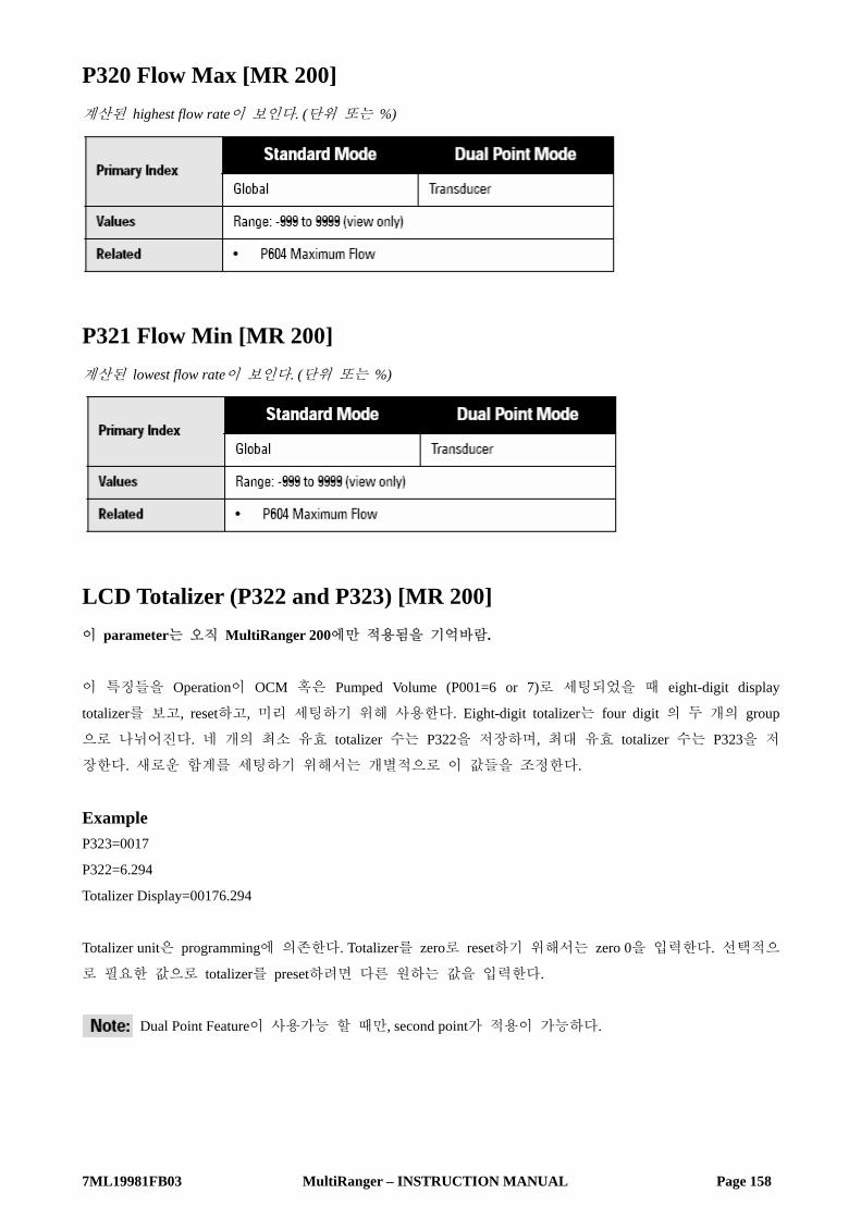
7ML19981FB03 MultiRanger – INSTRUCTION MANUAL Page 158
P320 Flow Max [MR 200] 계산된 highest flow rate이 보인다. (단위 또는 %)
P321 Flow Min [MR 200] 계산된 lowest flow rate이 보인다. (단위 또는 %)
LCD Totalizer (P322 and P323) [MR 200] 이 parameter는 오직 MultiRanger 200에만 적용됨을 기억바람.
이 특징들을 Operation이 OCM 혹은 Pumped Volume (P001=6 or 7)로 세팅되었을 때 eight-digit display
totalizer를 보고, reset하고, 미리 세팅하기 위해 사용한다. Eight-digit totalizer는 four digit 의 두 개의 group
으로 나뉘어진다. 네 개의 최소 유효 totalizer 수는 P322을 저장하며, 최대 유효 totalizer 수는 P323을 저
장한다. 새로운 합계를 세팅하기 위해서는 개별적으로 이 값들을 조정한다.
Example P323=0017
P322=6.294
Totalizer Display=00176.294
Totalizer unit은 programming에 의존한다. Totalizer를 zero로 reset하기 위해서는 zero 0을 입력한다. 선택적으
로 필요한 값으로 totalizer를 preset하려면 다른 원하는 값을 입력한다.
Dual Point Feature이 사용가능 할 때만, second point가 적용이 가능하다.

7ML19981FB03 MultiRanger – INSTRUCTION MANUAL Page 159
P322 LCD Total Low [MR 200] Totalizer 값의 4자리 최소 유효수를 보거나 그리고/또는 수정한다.
P323 LCD Total High [MR 200] Totalizer 값의 4자리 최대 유효수를 보거나 그리고/또는 수정한다.
Profile Records (P330 to P337)
이 parameter들은 Siemens Milltronics echo processing 기술과 관련된 권한이 주어진 서비스 제공자나 기술
자를 위한 것이다.
이 기능들은 수동으로 혹은 자동으로 시작되는 ten Echo profile 까지 record 될 수 있다. Hardware 와
Software 요구사항을 보는 Echo Profile을 위한 Scope Displays를 참고바람. Ten profile이 이미 저장이 되었다
면, 1부터 10까지 fill 되어 address 되므로 자동적으로 가장 오래된 처음 기록이 overwrite 된다. 수동적으
로는 처음의 records가 자동으로 overwrite 되지 않는다. 모든 records는 전원의 차단 결과로 자동적으로
지워진다.
Record가 보여질 때, 결과물은 현재의 Programming을 근거로 한다. 이는 echo parameter가 바뀌었을 때 관
찰되는 echo profile에 영향을 허용한다.

7ML19981FB03 MultiRanger – INSTRUCTION MANUAL Page 160
P330 Profile Record 이후의 판독을 위해 profile을 record 한다.
Differential 또는 Average operation은 MultiRanger 200의 특징임을 알아두기 바람.
Profile은 library에 기록됨과 함께, 이에 두 가지 기능을 제공한다 :
• 수동으로 echo profile을 기록하고 저장한다.
• 수동으로 혹은 자동으로 기록된 echo profile을 나타낸다.
Record address를 선택하기 위해서는
1. Program mode로 들어가서 index field를 보기 위해 Display 버튼을 두 번 누른다. Field는 두 개의
underscores를 나타낸다.
2. Index Number를 친다. Profile record information이 보여진다.
3. Record를 통해서 scroll하기 위해서는 ARROW 버튼을 사용한다.
수동으로 Profile을 기록하기 위해서는 Transducer를 활성화시키려면 TRANSDUCER 버튼을 누르고 display를 위해 Internal scope buffer에
echo profile을 기록한다.
MultiRanger 200 Feature Differential 또는 Average operation (P001=4 혹은 5)를 위해서는 scope Displays parameter에 transducer number
를 선택하기 위해서 접근한다.
MultiRanger 100 and MultiRanger 200 특징
Manual record를 저장하려면 Scope buffer에서 echo profile을 복사하기 위해서는 ENTER 버튼을 누르고 record library에서 선택된 address
에 이를 저장한다. Parameter value field는 new record information에 보여진다.

7ML19981FB03 MultiRanger – INSTRUCTION MANUAL Page 161
Record를 나타내려면 Display auxiliary mode로 들어가기 위해 버튼을 누른다. 그리고
• Oscilloscope 혹은 Dolphin Plus 상에서 display를 위해 scope buffer에 현재의 echo profile을 복사하기 위해
서 Transducer 버튼을 누른다.
Record를 지우려면 CLEAR를 누르고 선택된 adress에서 echo profile을 지우기 위해서 ENTER 버튼을 누른다. 값은 ---- 로 돌
아온다.
P331 Auto Record Enable Auto Profile Record 기능을 활성화/비활성화를 조정하기 위해 사용한다.
P332 Auto Record Transducer Auto Profile Records가 저장되는 Transducer Point Number를 지정한다.
Differential and Average operation은 MultiRanger 200의 기능임을 기억하기 바람.
MultiRanger 200 이 기능은 Point Number 1에 미리 설정된다. (조정은 differential 혹은 average Operation [P001=4 or 5] 이 선
택되었을 때만이 필요하다.

7ML19981FB03 MultiRanger – INSTRUCTION MANUAL Page 162
P333 Auto Record Interval 다른 Auto Profile Record가 저장되어질 수 있기 전에 Auto Profile Record가 저장된 후 시간을 경과시키기
위해 입력한다.
Auto Record ON and OFF Setpoints (P334 to P337) Auto Record ON Setpoint와 Auto Record OFF Setpoint는 Auto Profile Record로서 기대되는 결과 치로서의
Echo Profile을 위한 level 경계 사이를 정의하는 데 사용한다.
----이 P334 또는 P335 중에 나타난다면 Auto Profile Records는 현재의 level에 관계없이 저장이 된다.
Empty (P006)와 관계되는 Unit (P005) 혹은 Span의 % (P007)에서 level 값을 입력한다.
P334 Auto Record ON Setpoint Auto Record OFF Setpoint와의 결합에 있어 저장되는 Auto Profile Recoreds를 위한 경계를 정의하는 임계의
level을 입력한다.
P335 Auto Record OFF Setpoint Auto Record ON Setpoint와의 결합에 있어 저장되는 Auto Profile Recoreds를 위한 경계를 정의하는 임계의
level을 입력한다.

7ML19981FB03 MultiRanger – INSTRUCTION MANUAL Page 163
P336 Auto Record Filling / Emptying Level이 rising, falling이 되지 않을 때 이는 저장되는 것으로부터 Auto Profile Records를 제한하기 위해 이
기능을 사용한다.
Level이 Filling/Emptying Indicator (P702/P703) 와 상응하는 값 이상의 비율로 변한다면, Echo Profile은 이것
과 그리고 다른 Auto Profile Record restriction에 종속되어 저장된다.
P337 Auto Record LOE Time 연장된 LOE가 나타나지 않는다면 Auto Profile Records가 저장되는 것으로부터 제한된다.
LOE condition이 입력된 기간을 초과한다면, Echo Profile이 저장된다. 0으로 세팅되었을 때 LOE는 저장되
는 Auto Profile Record가 요구되지 않는다.

7ML19981FB03 MultiRanger – INSTRUCTION MANUAL Page 164
Installation Records (P340 to P342)
P340 Date of Manufacture MultiRanger Unit의 제조 일자를 보여준다.
P341 RUN Time 작동된 MultiRanger의 날의 누적을 보여준다.
Run time 값은 하루에 한 번 업데이트 되며, reset 할 수 없다. 전원의 단절되었을 경우, counter는 진행되
지 못한다. 그러므로, 통상의 기초에 있어서 전원이 단절된 unit은 정확한 값을 갖지 못할 것이다.
P342 Start Ups 제조 날 이래로 Number of times power가 적용이 되게 된다.

7ML19981FB03 MultiRanger – INSTRUCTION MANUAL Page 165
Open Channel Monitoring (P600 to P621) [MR 200] Open Channel Monitoring (OCM) operation은 MultiRanger 200의 유일한 특징이다.
MultiRanger가 Open channel flow로 사용된다면 다음의 요구되는 parameter가 수정되며 P621에 서술된
calibration이 수행된다.
일반적인 weirs와 flumes가 포함된 적용 가능한 예는 페이지 71의 Open Channel Monitoring을 참고바람.
Operation이 OCM (P001=6)으로 세팅되어 있을 때, MultiRanger는 Empty (P006) 혹은 OCM Zero Offset에 언
급된 head를 측정한다. Head에 근거한 Flowrate 또한 계산되어지고 LCD 상에 나타난다.
Water level이 Primary Measuring Device의 zero 지점 아래로 떨어진다면 LOE failure state에 입력되는 것을
피하기 위해서 Primary Measuring Device는 보다 긴 Range Extension (P801)이 요구된다. 보다 많은 정보를
위해서는 page 199의 Range Extension 부분을 참고하기 바란다.
P600 Primary Measuring Device [MR 200] 사용되는 Primary Measuring Device (PMD)의 type

7ML19981FB03 MultiRanger – INSTRUCTION MANUAL Page 166
MultiRanger는 일반적인 PMD flow calculation을 위해서 미리 program 된다. PMD가 리스트되지 않았다면,
알맞은 Universal Flow Calculation을 선택한다.
Max Head (P603), Max Flow (P604), Min Head (P605)와 연관된 parameter는 scroll로 접근되어질 수 있다.
Operation이 OCM (P001=6)으로 세팅되지 않았다면, 이 값은 0으로 미리 설정된다. Operation이 OCM으로
세팅되었다면, 이는 1로 미리 세팅된다.
P601 Flow Exponent [MR 200] Flow calculation 공식에서의 exponent
Primary Measuring Device (P600)이 1로 세팅되어 있다면 이 parameter를 사용한다. 이는 Max Head와 Zero
Head에 의해 세팅된 end point와 특정 설명에 근거한 곡선과 함께 Exponential curve를 만든다.
적용이 가능하다면 PMD manufacturer에 의한 exponent 혹은 아래에 주어진 sample 값을 사용하기 바란다.

7ML19981FB03 MultiRanger – INSTRUCTION MANUAL Page 167
Example Exponents
P602 Primary Measuring Device Dimensions [MR 200] Primary Measuring Device (PMD)의 Dimensions
Primary Measuring Device가 직접적으로 지원이 된다면 (P600=2,3,6,7) 이 parameter를 사용한다.
Dimensions는 각각의 PMD vary를 필요로 한다.
보다 많은 정보는 페이지 71의 PMD를 참고하기 바람.
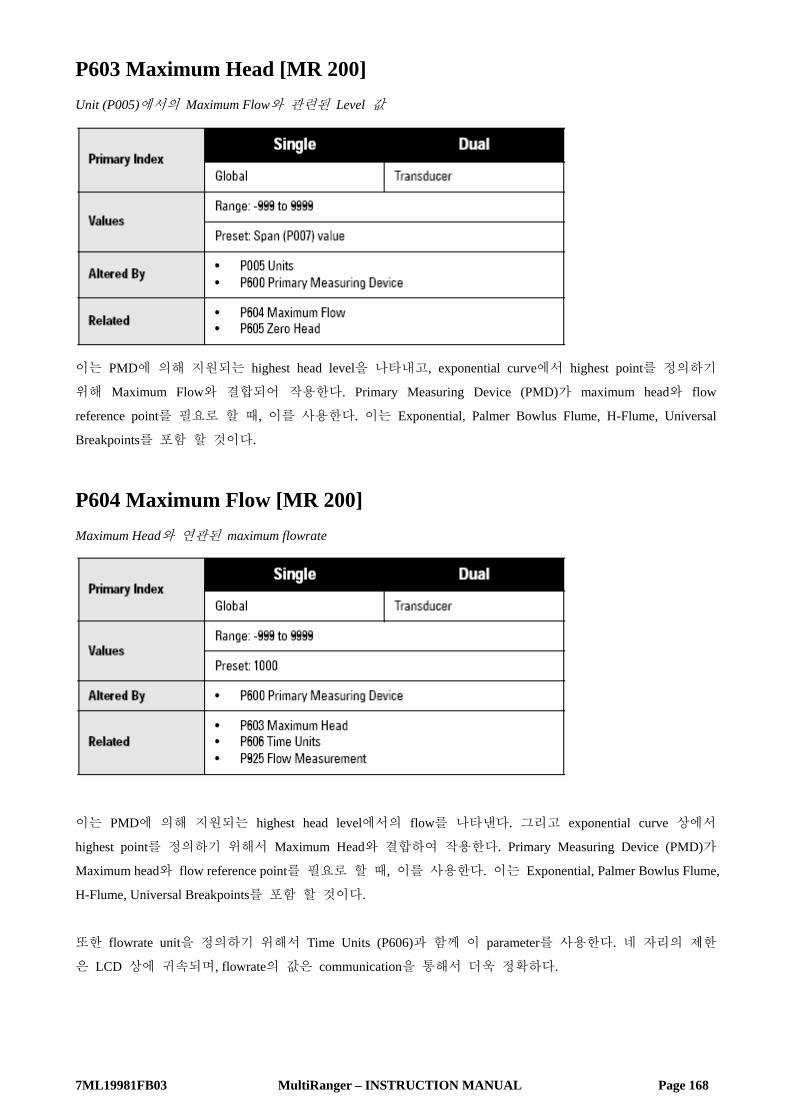
7ML19981FB03 MultiRanger – INSTRUCTION MANUAL Page 168
P603 Maximum Head [MR 200] Unit (P005)에서의 Maximum Flow와 관련된 Level 값
이는 PMD에 의해 지원되는 highest head level을 나타내고, exponential curve에서 highest point를 정의하기
위해 Maximum Flow와 결합되어 작용한다. Primary Measuring Device (PMD)가 maximum head와 flow
reference point를 필요로 할 때, 이를 사용한다. 이는 Exponential, Palmer Bowlus Flume, H-Flume, Universal
Breakpoints를 포함 할 것이다.
P604 Maximum Flow [MR 200] Maximum Head와 연관된 maximum flowrate
이는 PMD에 의해 지원되는 highest head level에서의 flow를 나타낸다. 그리고 exponential curve 상에서
highest point를 정의하기 위해서 Maximum Head와 결합하여 작용한다. Primary Measuring Device (PMD)가
Maximum head와 flow reference point를 필요로 할 때, 이를 사용한다. 이는 Exponential, Palmer Bowlus Flume,
H-Flume, Universal Breakpoints를 포함 할 것이다.
또한 flowrate unit을 정의하기 위해서 Time Units (P606)과 함께 이 parameter를 사용한다. 네 자리의 제한
은 LCD 상에 귀속되며, flowrate의 값은 communication을 통해서 더욱 정확하다.

7ML19981FB03 MultiRanger – INSTRUCTION MANUAL Page 169
Example
P605 Zero Head [MR 200] Zero head (Zero flow) 를 나타내는 단위 (P005) 상의 Empty (P006) 위의 거리
Zero reference가 Channel bottom보다 높은 곳에 위치하는 곳에 대개의 weirs와 flumes를 위해 이 기능은 사
용될 수 있다.

7ML19981FB03 MultiRanger – INSTRUCTION MANUAL Page 170
P606 Time Units [MR 200] 현재의 flow와 logging flow 값을 나타내기 위해 사용되는 unit을 결정한다.
이는 Primary Measuring Device가 Ratiometric (P608=0)일 때 사용된다.
Example
P607 Flowrate Decimal [MR 200] 나타나는 소수점 자리의 최대 수
Run mode에서 보여지는 소수점 자리 수는 display 능력을 초과하는 Flowrate의 digit 수를 방지하기 위해
서 자동적으로 변경이 된다.
Head 소수점의 최대 수는 Decimal Position (P060)에 의해 control 된다.

7ML19981FB03 MultiRanger – INSTRUCTION MANUAL Page 171
P608 Flowrate Units [MR 200] Total Flow를 나타내기 위해 사용되는 Volume Units
BS-3680/ISO 4359 Rectangular Flume 혹은 BS-3680/ISO 1438/1 Thin Plate V-Notch Weir (P600=6 혹은 7)을 사
용할 때만 이 parameter를 세팅한다. P600=1에서 5일 때, P608을 위한 0의 default 값을 사용한다.
Primary Measuring Device (PMD)이 완벽한 calculation (P600=6,7)을 지원할 때, 이 parameter 기능을 할 수
있다. 완벽한 PMDs (P600=6,7)에 있어서 volume unit은 이 parameter를 사용함으로 특징화될 수 있다. 만약
필요하다면, 완벽한 PMDs는 다른 unit을 고려하기 위해서 Ratiometric (P608=0)을 사용할 수 있다.

7ML19981FB03 MultiRanger – INSTRUCTION MANUAL Page 172
P610 Head Breakpoints [MR 200] Flowrate이 알려진 Head Breakpoints. 더 많은 정보를 원한다면 Page 117의 Accessing a Secondary Index를
보기 바란다.
flowrate가 알려진 Span 상에서의 값. Universal flow를 특정화하는 방법을 알아보려면 페이지 81의
Universal Calculation Support를 보기 바람.
P611 Breakpoint Flowrates [MR 200] 각각의 입력되는 Head Breakpoint에 상응하는 flowrate.
이는 관계된 Breakpoint를 위한 flowrate 이다. Universal flow를 특정화하는 방법을 알아보려면 페이지 81
의 Universal Calculation Support를 보기 바람.

7ML19981FB03 MultiRanger – INSTRUCTION MANUAL Page 173
P620 Low Flow Cutoff [MR 200] Cutoff 값 이하에서 flow를 위한 totalizer activity를 제거한다.
이는 units (P005) 상에서의 minimum head 혹은 Span의 percent로서 입력을 위해 사용한다.
P621 Auto Zero Head [MR 200] 실제적인 head measurements에 근거한 Zero Head (P605)를 조정한다.
정해진 양에 의해 reported head가 연속적으로 high 혹은 low일 때, 이 parameter를 사용한다.
이 기능을 사용하기 전에, 다음의 parameter들이 정확한지를 확인한다. • Empty (P006)
• Temperature (P664)
• Offset Reading (P062=0)
• Zero Head Offset (P605)
Procedure, with “Head” steady 1. 계산된 Head를 나타내기 위해 Transducer 버튼을 누른다.
2. Repeatability를 확인하기 위해서 적어도 5회 정도는 Step One을 반복한다.
3. 실제적인 Head 값을 측정한다.
4. 실제적인 Head 값을 입력한다.
입력된 Empty (P006) 값과 조정된 Empty 값의 편차는 Offset Correction (P652)에 저장된다. 선택적으로,
Empty parameter (P006)은 직접적으로 고쳐질 수 있다.
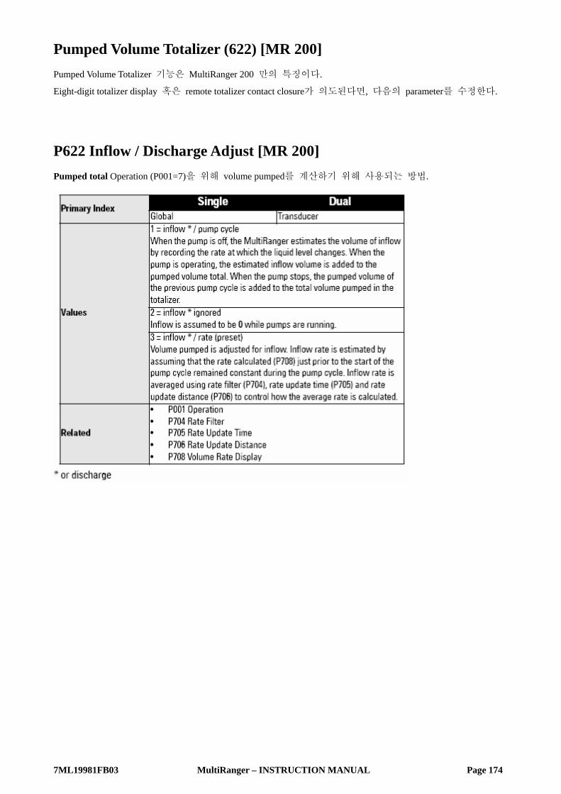
7ML19981FB03 MultiRanger – INSTRUCTION MANUAL Page 174
Pumped Volume Totalizer (622) [MR 200] Pumped Volume Totalizer 기능은 MultiRanger 200 만의 특징이다.
Eight-digit totalizer display 혹은 remote totalizer contact closure가 의도된다면, 다음의 parameter를 수정한다.
P622 Inflow / Discharge Adjust [MR 200] Pumped total Operation (P001=7)을 위해 volume pumped를 계산하기 위해 사용되는 방법.

7ML19981FB03 MultiRanger – INSTRUCTION MANUAL Page 175
Totalizer (P630 to P645) [MR 200] Totalizer 기능은 MultiRanger 200에서만 적용된다.
P630 LCD Totalized Multiplier [MR 200] LCD Total 증가량이 너무 크거나 혹은 작을 때, 이 기능을 사용한다.
LCD 상의 display보다 우선하는 실제적인 volume이 나뉘어진 factor (powers of 10 only)를 입력한다. 이 값
을 사용하면 eight-digit totalizer는 판독치의 사이에서 초과하여 진행되지 않는다.
Example : Volume units의 1000s 상에서 LCD Total display를 위해 3을 입력한다.

7ML19981FB03 MultiRanger – INSTRUCTION MANUAL Page 176
P633 LCD Totalized Decimal Position [MR 200] 나타내어지는 소수점 자리의 최대수를 입력한다.
MultiRanger 200의 초기 commissioning 동안의 소수점 자리를 세팅한다. Position이 나중에 변한다면, P322
과 P323에서의 totalizer data는 틀려질 것이며 새로운 소수점 값에 의해 다시 set되어야만 한다.
Run mode에서 보여지는 소수점 자리 수는 자동적으로 수정되지 않는다. LCD Total 값이 나타낼 수 있는
범위를 초과한 값일 경우에 이 Total은 0으로 돌아가져 진행을 계속한다.
P640 Remote Totalized Multiplier [MR 200] Remote totalizer (totalizer operation [relay Function, P111=40]을 위해 세팅된 relay에 연결된 계기)가 너무 빠
르게 혹은 느리게 업데이트 된다면, 이 기능을 사용한다.
Parameter는 Operation이 OCM 혹은 Pumped Volume (P001=6 혹은 7)로 세팅되어 있다면 관계한다.
MultiRanger상의 relay는 2.5 Hz의 maximum frequency를 갖는다.

7ML19981FB03 MultiRanger – INSTRUCTION MANUAL Page 177
Remote totalizer count increment에 우선하는 실제적인 volume이 나뉘어지는 factor (powers of 10 only)를 입력
한다.
Example : Remote Totalizer 상에서 volume units의 1000s 의 값으로 업데이트 하려면 3을 입력한다.
P641 Flow Sampler Mantissa [MR 200] 이 기능은 Flow Sampler (flow sampler operation Relay Function을 위한 MultiRanger relay에 연결된 계기) 진행
에 필요한 flow unit의 수를 정하기 위해 Flow Sampler Exponent (P642)와 결합하여 사용한다.
이 parameter는 Operation이 OCM (P001=6)으로 세팅되어 있을 경우에만 관계한다.
공식 상에서 exponent (Z)와 관계하는 mantissa (Y)를 입력한다 : Flow Sampler Increment = Y x 10Z Flow units.
Example : 매 4310 (4.31x10³) flow unit마다 한번 count 하려면 :
• P641은 4.31 그리고 P642는 3으로 세팅한다.
P642 Flow Sampler Exponent [MR 200] 이 기능은 Flow Sampler (flow sampler operation Relay Function을 위한 MultiRanger relay에 연결된 계기) 진행
에 필요한 flow unit의 수를 정하기 위해 Flow Sampler Mantissa (P641)와 결합하여 사용한다.

7ML19981FB03 MultiRanger – INSTRUCTION MANUAL Page 178
이 parameter는 Operation이 OCM (P001=6)으로 세팅되어 있을 경우에만 관계한다.
공식 상에서 Mantissa (Y)와 관계하는 Exponent (Z)를 입력한다 : Flow Sampler Increment = Y x 10Z Flow units.
P645 Relay Duration [MR 200] 이 기능은 totalizer, flow sampler, time (control), aeration (P111=40,41,60 혹은 62)에서 relay set의 지속 동안
minimum contact closure를 수정하기 위해서 이 기능을 사용한다.
연결된 계기에 의해 필요로 하는 minimum contact closure duration (in seconds)을 입력한다.
Flow sampler function 상에서 이 값은 relay의 ON time과 Contacts 사이에서 OFF time을 위해 사용된다.
Range Calibration (P650 to P654) 가능한 calibration의 type은 두 가지이다.
Offset : 정해진 양에 의해서 측정을 수정한다.
Sound Velocity : Sound의 speed를 조정하고 측정 계산을 바꾼다.
Sound Velocity calibration이 행해지지 않았다면, offset calibration을 steady level에서 수행한다.
Calibration이 행해졌다면 알려진 high level에서 Offset 그리고 알려진 low level에서 Sound Velocity를 행한
다.
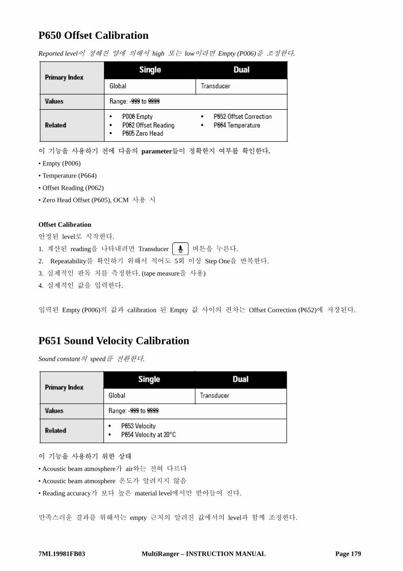
7ML19981FB03 MultiRanger – INSTRUCTION MANUAL Page 179
P650 Offset Calibration Reported level이 정해진 양에 의해서 high 또는 low이라면 Empty (P006)을 조정한다.
이 기능을 사용하기 전에 다음의 parameter들이 정확한지 여부를 확인한다.
• Empty (P006)
• Temperature (P664)
• Offset Reading (P062)
• Zero Head Offset (P605), OCM 사용 시
Offset Calibration
안정된 level로 시작한다.
1. 계산된 reading을 나타내려면 Transducer 버튼을 누른다.
2. Repeatability를 확인하기 위해서 적어도 5회 이상 Step One을 반복한다.
3. 실제적인 판독 치를 측정한다. (tape measure을 사용)
4. 실제적인 값을 입력한다.
입력된 Empty (P006)의 값과 calibration 된 Empty 값 사이의 편차는 Offset Correction (P652)에 저장된다.
P651 Sound Velocity Calibration Sound constant의 speed를 전환한다.
이 기능을 사용하기 위한 상태
• Acoustic beam atmosphere가 air와는 전혀 다르다
• Acoustic beam atmosphere 온도가 알려지지 않음
• Reading accuracy가 보다 높은 material level에서만 받아들여 진다.
만족스러운 결과를 위해서는 empty 근처의 알려진 값에서의 level과 함께 조정한다.

7ML19981FB03 MultiRanger – INSTRUCTION MANUAL Page 180
Using Sound Velocity Calibration
어떤 한 지점의 low 값에서 안정된 level을 확인한다. (P653과 P654는 적절히 수정함)
1. vapor concentration을 안정화시키기 위해서 충분한 시간을 배분한다.
2. 계산된 판독 치를 나타내기 위해서 Transducer 버튼을 누른다.
3. Repeatability를 확인하기 위해서 적어도 5회 이상은 Step Two를 반복한다.
4. 실제적인 판독 치를 측정한다.
5. 실제적인 값을 입력한다.
마지막 Sound Velocity calibration이 행해졌을 때 atmosphere type, concentration, temperature conditions가 다르
다면 이 절차를 반복한다.
Air 이외의 Gas에서 온도 편차는 sound의 speed 편차와 상응하지는 않는다. 온도 센서를 끄고 고정 온도
를 사용한다.
P652 Offset Correction Offset Calibration이 행해졌을 때 수정된 값.
선택적으로 요구되는 Offset Correction의 양이 알려진다면, display전에 Reading에 더해져야 하는 양을 입
력한다.
P653 Velocity 20℃ (P654) vs. air의 Temperature (P664) characteristics에서 Sound Velocity에 근거한 조정된 값.
선택적으로 현재의 Sound Velocity를 입력하거나, Sound Velocity Calibration을 수행한다. (P651) P005=1,2 혹
은 3일 때, 사용되는 단위는 m/s 이다.

7ML19981FB03 MultiRanger – INSTRUCTION MANUAL Page 181
P654 Velocity at 20℃ 이 값은 Sound Velocity (P653)을 자동적으로 계산하기 위해 사용된다.
Sound Velocity Calibration을 수행한 후에, acoustic beam atmosphere가 공기 (344.1 m/s 혹은 1129 ft/s) 임을 확
인하기 위해서 이 값을 체크한다.
선택적으로 20℃에서 acoustic beam atmosphere sound velocity가 알려지고, sound velocity vs. temperature
characteristics가 air의 그것과 비슷하다면, sound velocity를 입력한다.
P005=1,2 혹은 3일 때 (혹은 P005=4 혹은 5일 때 ft/s) 사용되는 단위는 m/s이다.
Temperature Compensation (P660 to P664)
P660 Temp Source Temperature reading의 Source는 sound의 speed를 조정하는데 사용한다.
MultiRanger는 transducer에 할당된 TS-3 temperature sensor를 사용한다. 이것이 연결되어 있지 않다면
Ultrasonic/temperature transducer가 사용된다. Transducer가 내부 temperature sensor를 가지고 있지 않다면
Temp Fixed 값이 사용된다.
Acoustic beam atmosphere temperature가 transducer로부터 거리에 따라 변화한다면, TS-3 Temperature Sensor와
Ultrasonic/temperature transducers를 연결하고 Average를 선택한다.

7ML19981FB03 MultiRanger – INSTRUCTION MANUAL Page 182
Air가 아닌 Gas에서 Temperature 편차는 sound speed의 편차와 상응하지는 않는다. 이런 경우에
temperature sensor를 끄고 고정된 temperature를 사용한다.
P661 Temp Fixed Temperature sensing device가 사용되지 않는다면 이 기능을 사용한다.
Transducer acoustic beam 이내의 atmosphere의 temperature (in ℃)를 입력한다. 만약 transducer로부터
Temperature가 거리에 따라 변화한다면 average temperature를 입력한다.
P663 Temperature Transducer Allocation 이 기능은 Differential 혹은 Average Operation (P001=4혹은 5)를 위해서 사용이 허용된다.
preset일 경우에 Ultrasonic/Temperature Transducer One과 Two의 temperature measurement는 Points 1과 2에 개
별적으로 할당되게 된다.
양쪽 Transducer로부터 temperature measurement가 동일해야 하지만 하나가 radiant heat source에 가깝게 위
치한다면 이 기능을 사용한다. 다른 transducer의 temperature measurement를 양쪽 transducer Point Number에
할당한다.
Transducer의 temperature measurement가 나타나는 Point Number의 원거리 계산을 위해 사용되어질
transducer의 수를 입력한다. 양쪽 transducer가 Point Number에 할당되어졌을 때, 각각의 temperature
measurement는 평균화된다.
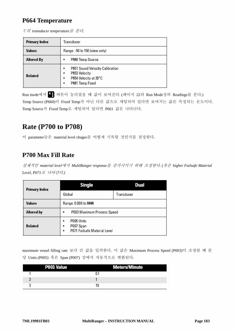
7ML19981FB03 MultiRanger – INSTRUCTION MANUAL Page 183
P664 Temperature ℃의 transducer temperature를 본다.
Run mode에서 버튼이 눌러졌을 때 값이 보여진다. (페이지 22의 Run Mode상의 Readings를 본다.)
Temp Source (P660)이 Fixed Temp가 아닌 다른 값으로 세팅되어 있다면 보여지는 값은 측정되는 온도이다.
Temp Source가 Fixed Temp로 세팅되어 있다면 P661 값은 나타난다.
Rate (P700 to P708) 이 parameter들은 material level chages를 어떻게 기록할 것인지를 결정한다.
P700 Max Fill Rate 실제적인 material level에서 MultiRanger response를 증가시키기 위해 조정한다. (혹은 higher Failsafe Material
Level, P071로 나아간다.)
maximum vessel filling rate 보다 큰 값을 입력한다. 이 값은 Maximum Process Speed (P003)이 조정될 때 분
당 Units (P005) 혹은 Span (P007) 상에서 자동적으로 변환된다.

7ML19981FB03 MultiRanger – INSTRUCTION MANUAL Page 184
P701 Max Empty Rate 실제적인 material level에서 MultiRanger response를 감소시키기 위해 조정한다. (혹은 lower Failsafe Material
Level, P071로 나아간다.)
maximum vessel emptying rate 보다 큰 값을 입력한다. 이 값은 Maximum Process Speed (P003)이 조정될 때
분당 Units (P005) 혹은 Span (P007) 상에서 자동적으로 변환된다.
P702 Filling Indicator LCD Filling indicator를 기능화시키기 위해 요구되는 Fill Rate
이 값 (분당 P005의 단위 혹은 P007 Span의 %)은 Max Fill Rate (P700)의 1/10으로 자동으로 세팅된다.

7ML19981FB03 MultiRanger – INSTRUCTION MANUAL Page 185
P703 Emptying Indicator LCD Emptying indicator를 기능화시키기 위해 요구되는 Empty Rate
이 값 (분당 P005의 단위 혹은 P007 Span의 %)은 Max Empty Rate (P701)의 1/10으로 자동으로 세팅된다.
P704 Rate Filter Rate Value (P707) fluctuations을 둔화시킨다.
Display가 업데이트되기 전에 Rate Value가 계산되어지는 time 혹은 distance interval를 입력한다.
이는 Maximum Process Speed (P003)에 따라서 자동적으로 수정된다.
이 값은 Rate Update Time (P705) 와/혹은 Rate Update Distance (P706)을 자동으로 수정한다. 선택적으로 이
parameter 값들은 독립적으로 수정되어질 수 있다.

7ML19981FB03 MultiRanger – INSTRUCTION MANUAL Page 186
P705 Rate Update Time Rate Value update되기 전, material level rate of change가 평균화되는 time period
P706 Rate Update Distance Rate Value update가 개시되기 위한 material level 변화
P707 Rate Value Material level change (분당 P005의 단위 혹은 P007 Span의 %)
Negative rate은 vessel이 비어 있음을 나타낸다.
페이지 22의 Run mode 상의 Readings에 서술된 것처럼 Run mode에서 버튼이 눌러졌을 때 이는 보여
지는 값이다.

7ML19981FB03 MultiRanger – INSTRUCTION MANUAL Page 187
P708 Volume Rate Display [MR 200] 분당 maximum volume의 percent 상에서 volume의 값의 Rate.
이 기능은 오직 MultiRanger 200에만 적용됨을 기억하기 바람.
이 값은 pumped volume applications (P622=3)에서 inflow를 계산하기 위해서 내부적으로 사용된다.
Percent와 Volume 사이에서 toggle로 고정시키기 위해서 와 같은 READING 버튼을 누른다.
Measurement Verification (P710 to P713)
P710 Fuzz Filter Echo Lock Window (P713) 내의 level fluctuations (rippling 혹은 splashing liquid surface)로 인한 기록되는 레벨
을 안정화시키기 위해서 이를 사용한다.
이 값 (P007, Span의 %)은 Maximum Process Speed (P003)이 수정되어질 때 자동적으로 수정된다.
보다 높은 값이 입력될수록, 보다 큰 fluctuation이 안정화된다.
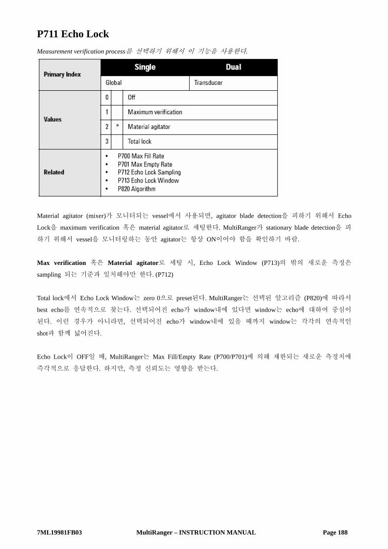
7ML19981FB03 MultiRanger – INSTRUCTION MANUAL Page 188
P711 Echo Lock Measurement verification process를 선택하기 위해서 이 기능을 사용한다.
Material agitator (mixer)가 모니터되는 vessel에서 사용되면, agitator blade detection을 피하기 위해서 Echo
Lock을 maximum verification 혹은 material agitator로 세팅한다. MultiRanger가 stationary blade detection을 피
하기 위해서 vessel을 모니터링하는 동안 agitator는 항상 ON이어야 함을 확인하기 바람.
Max verification 혹은 Material agitator로 세팅 시, Echo Lock Window (P713)의 밖의 새로운 측정은
sampling 되는 기준과 일치해야만 한다. (P712)
Total lock에서 Echo Lock Window는 zero 0으로 preset된다. MultiRanger는 선택된 알고리즘 (P820)에 따라서
best echo를 연속적으로 찾는다. 선택되어진 echo가 window내에 있다면 window는 echo에 대하여 중심이
된다. 이런 경우가 아니라면, 선택되어진 echo가 window내에 있을 때까지 window는 각각의 연속적인
shot과 함께 넓어진다.
Echo Lock이 OFF일 때, MultiRanger는 Max Fill/Empty Rate (P700/P701)에 의해 제한되는 새로운 측정치에
즉각적으로 응답한다. 하지만, 측정 신뢰도는 영향을 받는다.

7ML19981FB03 MultiRanger – INSTRUCTION MANUAL Page 189
P712 Echo Lock Sampling Sampling Criterion은 측정하기 전에 발생해야만 하는 현재 Lock된 echo의 위, 아래에 나타나는 연속적인
echo의 수를 세팅하는데, 이는 new reading으로 유효하다. (Echo Lock P711 값 : 1 혹은 2).
Example : Setting
• P711=2, material agitator
• P711=5 : 2
Result
• new reading은 현재의 reading이 발생하는 것보다 5개 연속적인 측정치보다 높지 않거나 혹은 2개 연속
적인 측정치보다 낮지 않다면 유효하지 않을 것이다.
• Resetting P711은 P712를 개별적인 미리 설정된 값으로 되돌린다.
P713 Echo Lock Window Echo Lock Window의 size를 수정한다.

7ML19981FB03 MultiRanger – INSTRUCTION MANUAL Page 190
Echo Lock Window는 echo의 중심에 맞추어지고 또한 Reading을 이끌어내기 위해 사용되는 Distance
Window (units P005) 이다. New measurement가 window에 있을 때, 이는 다시 중심이 맞춰지고 새로운
Reading이 계산된다. 이와는 다르게, New measurement는 reading이 업데이트되기 전에 Echo Lock (P711)에
의해 확인된다.
0이 입력되었을 때 각각의 측정 후에 Window는 자동적으로 계산된다. Slower P003 maximum Process Speed
values에서는 window는 좁아지며, faster P003 values에서는 window는 보다 넓어진다.
Transducer Scanning (P726 to P729)
P726 Level System Sync Terminal block 상에서 System Sync를 활성화시킨다.
다른 level measurement system이 가깝게 설치되었다면, 이를 사용한다. 그리고 Sync terminal 상에 함께
wiring 한다.
P727 Scan Delay Transducer points로부터의 측정치 사이의 초 단위의 Delay (Dual Point model에서만 적용).
이 기능은 next point가 scan 되기 전에 Delay를 수정하는 것에만 사용이 가능하다. 초 단위의 delay의 양
을 입력한다. Maximum Process Speed (P003)이 수정될 때, 이 값은 자동적으로 수정이 된다.

7ML19981FB03 MultiRanger – INSTRUCTION MANUAL Page 191
P728 Shot Delay Transducer shots 사이의 초 단위의 Delay.
vessel 이내의 일시적인 acoustic noise가 echo로 인해서 다음에서 받아들여지는 것에 부정적인 영향을 준
다면 이를 사용한다. 하나 이상의 ultrasonic unit이 여분을 위해서 설치되어 있다면, 이 값은 0이어야 한
다.
P729 Scan Time 나타나는 point가 마지막으로 Scan된 이래로 경과된 초 단위의 시간을 보여준다.
이는 Run mode에서 Auxiliary Reading으로서 보여지게 된다.
Display (P730 to P739)
P730 Auxiliary Reading 이 기능은 operator가 Auxiliary Readings을 임시적으로 또는 계속적으로 선택했던 것을 나타내기 위해 사
용한다.
Auxiliary Reading을 임시적으로 나타내기 위해서 OFF를 선택한다. 다른 Auxiliary Reading을 선택하거나
혹은 Programming mode가 입력될 때까지 Auxiliary Reading을 나타내기 위해서 HOLd를 선택한다. 페이지
26의 Run mode auxiliary readings를 위한 Hand Programmer 부분을 보기 바람.
Auxiliary Reading operation의 선택
1. Auxiliary Function symbol을 나타내기 위해서 READING 을 누른다.
2. OFF 혹은 HOLd option에 접근하기 위해서 ARROWS 을 누른다.
3. ENTER를 누른다.

7ML19981FB03 MultiRanger – INSTRUCTION MANUAL Page 192
필요하다면, Auxiliary Reading display 상에서 Default를 위해서 Parameter Number를 입력한다. 그 값은
default에 의해서 auxiliary reading area에 보여질 것이다. 다른 값들은 적용이 가능하지만 이곳에 규정된
parameter에 reset될 것이다.
P731 Auxiliary Reading Key Parameter Number의 값이 Auxiliary Reading field에 보여지게 되는 Parameter Number를 입력한다.
는 Run mode에서 누른다. 페이지 26의 Run mode auxiliary readings의 Hand Programmer 부분을 보
기 바란다.
P732 Display Delay Point Number display scroll speed를 조정한다.
Display가 다음의 Point Number로 진행하기 전에 Delay를 수정하기 위해서 이 기능을 사용한다.
Display scrolling은 Transducer scanning과는 개별적이다.
P733 Scroll Access 의도하는 parameter scroll access option을 선택하기 위해서 이 기능을 사용한다.
접근되는 parameter를 tag/untag하기 위해서는 READING 과 를 누른다. 는 접근되는 parame
ter가 tag 되었다는 것을 나타내기 위해서 보여진다.
NOTE : Quick Start parameters (P001-P007)와 Factory default settings로부터 변환된 값들은 untag되어질 수 없
다.

7ML19981FB03 MultiRanger – INSTRUCTION MANUAL Page 193
P735 Backlight LCD backlighting을 control 한다.
backlight은 임의로 켜지거나 꺼질 수 있으며 Programmer에 의해서 제어될 수도 있다. 이런 경우에 있어
이는 마지막으로 버튼이 눌러지고 30초 후에 꺼지게 된다.
P737 Primary Reading [MR 200] Run mode일 경우에 Primary reading display 상에 보여지는 판독 값.
이 값이 toggle을 가리킬 때, 두 reading (default와 totalizer)는 Display delay (P732) 상에 지정된 time에 보여
지게 된다.

7ML19981FB03 MultiRanger – INSTRUCTION MANUAL Page 194
SmartLinx Reserved (750 to 769) 이 parameter들은 Optional SmartLinx communications cards에 할당되어 있으며 card에 의해 변화된다. 이들
중 사용되는 것이 있다면 결정하기 위해서 SmartLinx documentation을 참고하기 바란다.
Communications (P770 to P782) MultiRanger communication port는 port에 의해서 index된 parameter의 series에 의해 조정된다.
Communications set-up의 설명을 위해서는 페이지 87의 Communication 부분을 참고하기 바란다.
다른 말이 없다면 Communication parameter들은 이 communication port에 index 된다.
P770 Port Protocol MultiRanger와 Device 사이에서 사용되는 Communications protocol.
MultiRanger는 ASCⅡ와 RTU formats에서 내부적으로 규정된 Modbus standard를 지원한다. 다른 Protocol은
optional SmartLinx cards와 함께 적용이 된다.
P771 Network Address Network 에서의 MultiRanger의 유일한 identifier.
Siemens Milltronics protocol에 연결된 계기에서 이 parameter는 무시된다. Serial Modbus slave protocol에 연결
된 계기에서 이 parameter는 1-247로부터의 수이다. Network administrator는 network상의 모든 계기는 유일
한 address를 가지고 있음을 확인하여야 한다. Broadcast address이며 slave 계기에 알맞지 않을 경우
Modbus를 위해서 0이라는 값을 사용하지 않는다.

7ML19981FB03 MultiRanger – INSTRUCTION MANUAL Page 195
P772 Baud Rate Master device와 함께하는 communication rate.
이는 Kbaud에서 communication의 rate을 규정한다. 어떠한 값이라도 입력은 될 수 있지만 위에 보여진 값
만이 지원된다. Baud rate은 연결된 하드웨어의 speed 그리고 사용되는 protocol를 반영해야만 한다.
P773 Parity Serial port parity.
Communications parameters는 MultiRanger와 모든 연결된 계기 사이에서 동일하다. 예를 들면, 많은
modems에서 No parity, 8 data bits, 1 stop bit인 N-8-1로 default 된다.
P774 Data Bits Character 마다의 data number.
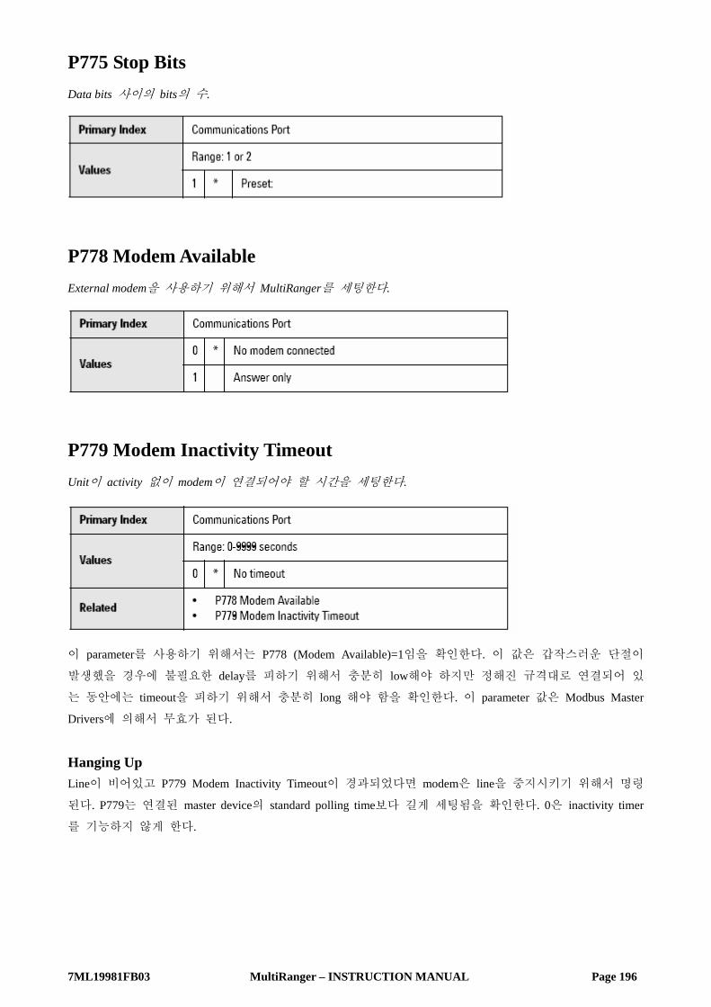
7ML19981FB03 MultiRanger – INSTRUCTION MANUAL Page 196
P775 Stop Bits Data bits 사이의 bits의 수.
P778 Modem Available External modem을 사용하기 위해서 MultiRanger를 세팅한다.
P779 Modem Inactivity Timeout Unit이 activity 없이 modem이 연결되어야 할 시간을 세팅한다.
이 parameter를 사용하기 위해서는 P778 (Modem Available)=1임을 확인한다. 이 값은 갑작스러운 단절이
발생했을 경우에 불필요한 delay를 피하기 위해서 충분히 low해야 하지만 정해진 규격대로 연결되어 있
는 동안에는 timeout을 피하기 위해서 충분히 long 해야 함을 확인한다. 이 parameter 값은 Modbus Master
Drivers에 의해서 무효가 된다.
Hanging Up Line이 비어있고 P779 Modem Inactivity Timeout이 경과되었다면 modem은 line을 중지시키기 위해서 명령
된다. P779는 연결된 master device의 standard polling time보다 길게 세팅됨을 확인한다. 0은 inactivity timer
를 기능하지 않게 한다.

7ML19981FB03 MultiRanger – INSTRUCTION MANUAL Page 197
P782 Parameter Index Location Index information이 parameter access area에 저장되는 곳을 결정한다.
Global (0) Primary와 Secondary index 값들은 전체적으로 영향을 미친다. (이들은 즉각적으로 parameter access area의
모든 곳에 영향을 미친다.) 그리고 저장된다 :
• Primary index – R43,999
• Secondary index – R43,998
Parameter – Specific (1) Primary와 Secondary index 값은 R46000과 R46999 사이에서 갖추어진 format words에 인코딩 된다. 각각의
Format work는 Parameter access map에서의 R44000 series number와 상응하게 된다. 예를 들면, format register
R46111은 parameter P111과 상응하며 이 값은 R44111에 저장된다. Modbus protocol (P770=2 혹은 3)이 사용
되지 않는다면 이 parameter는 무효화 된다.
SmartLinx Hardware Testing 이 parameter는 테스트를 위해서 사용되며 SmartLinx Card의 bug를 없앤다.
P790 Hardware Error Communications 회로에서 계속되는 Hardware test의 결과.
P790 (hardware error)에서 Fail 혹은 Err1이 보여질 때, error에 관한 information을 위해서 P791 (hardware
error code)와 P792(hardware error count)로 간다.

7ML19981FB03 MultiRanger – INSTRUCTION MANUAL Page 198
P791 Hardware Error Code P790으로부터 Fail 혹은 ERR1의 정확한 원인을 나타낸다.
P792 Hardware Error Count 각 time 마다 P790에 Fail이 기록되는 1씩 증가되는 Count.
P794 SmartLinx Module Type
SmartLinx가 사용될 때 이 parameter는 module type을 확인하기 위해서 사용된다. SmartLinx를 사용하지 않
는다면, 이 parameter는 기능하지 않는다. 이 parameter와 전체적인 설명이 있는 SmartLinx 부분을 보기
바람.
P795 SmartLinx Protocol
SmartLinx가 사용될 때 이 parameter는 Protocol을 확인하기 위해서 사용된다. SmartLinx를 사용하지 않는
다면, 이 parameter는 기능하지 않는다. 이 parameter와 전체적인 설명이 있는 SmartLinx 부분을 보기 바
람.
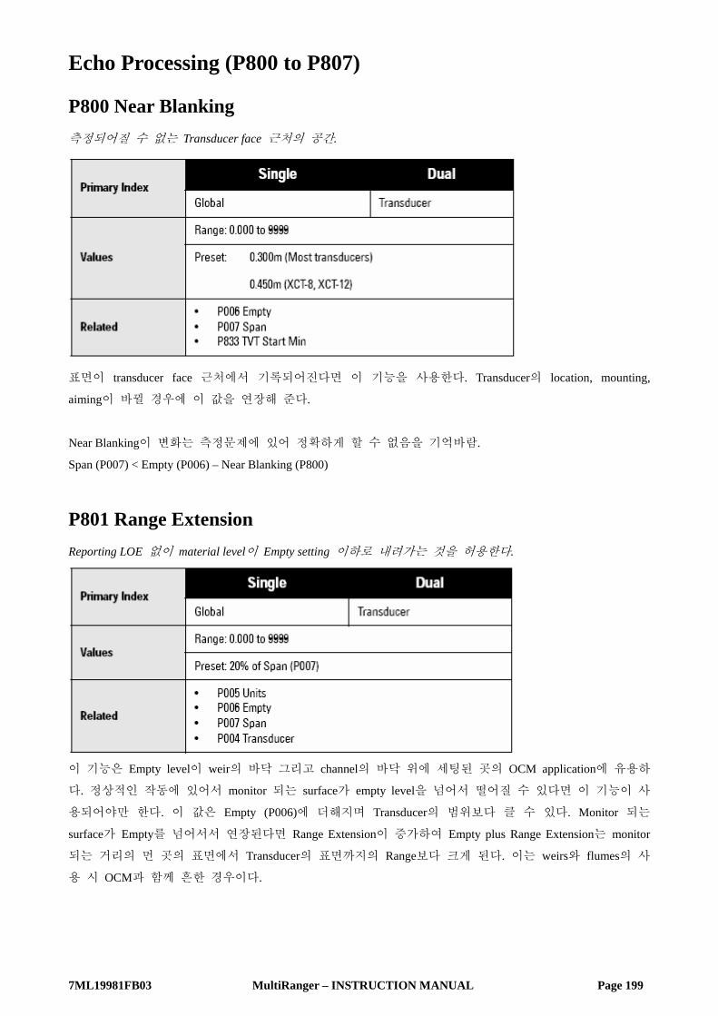
7ML19981FB03 MultiRanger – INSTRUCTION MANUAL Page 199
Echo Processing (P800 to P807)
P800 Near Blanking 측정되어질 수 없는 Transducer face 근처의 공간.
표면이 transducer face 근처에서 기록되어진다면 이 기능을 사용한다. Transducer의 location, mounting,
aiming이 바뀔 경우에 이 값을 연장해 준다.
Near Blanking이 변화는 측정문제에 있어 정확하게 할 수 없음을 기억바람.
Span (P007) < Empty (P006) – Near Blanking (P800)
P801 Range Extension Reporting LOE 없이 material level이 Empty setting 이하로 내려가는 것을 허용한다.
이 기능은 Empty level이 weir의 바닥 그리고 channel의 바닥 위에 세팅된 곳의 OCM application에 유용하
다. 정상적인 작동에 있어서 monitor 되는 surface가 empty level을 넘어서 떨어질 수 있다면 이 기능이 사
용되어야만 한다. 이 값은 Empty (P006)에 더해지며 Transducer의 범위보다 클 수 있다. Monitor 되는
surface가 Empty를 넘어서서 연장된다면 Range Extension이 증가하여 Empty plus Range Extension는 monitor
되는 거리의 먼 곳의 표면에서 Transducer의 표면까지의 Range보다 크게 된다. 이는 weirs와 flumes의 사
용 시 OCM과 함께 흔한 경우이다.

7ML19981FB03 MultiRanger – INSTRUCTION MANUAL Page 200
P802 Transducer with Submergence Shield 때때로 Transducer가 잠기는 것이 예상될 때 이를 사용한다.
submergence shield와 함께 Transducer가 잠길 때, shield는 special echo를 만드는 air pocket을 trap 한다.
MultiRanger는 echo를 분간하고 highest level 까지 나아가며 그것에 맞게 작동되고 나타나고 출력한다. 이
기능은 Transducer가 잠기는 동안에 전원이 되돌아 왔을 때 유효하다.
P803 Shot / Pulse Mode 어떤 type의 ultrasonic shot이 발사되는지 (작동하는지) 결정한다.
모니터되는 surface가 Transducer 표면에 가깝게 위치할 때 MultiRnager response를 증가시킨다. Transducer에
서 표면까지의 거리에 관계없이 각각의 측정에 있어서 short 그리고 long의 발사되는 acoustic shot을 갖기
위해 short and long을 선택한다. Short shot에 의해서 만들어지는 Echo Confidence (P805)가 short Confidence
Threshold (P804)를 초과하거나 monitored surface가 Short Shot Range (P852) 이내에 있다면 오직 short shot
fired를 가지기 위해서 short를 선택한다.

7ML19981FB03 MultiRanger – INSTRUCTION MANUAL Page 201
P804 Confidence Threshold Software에 의해서 수치화되는 echo를 결정한다.
부정확한 material level이 기록될 때 이 기능을 사용한다. Short and long shot Confidence Thresholds는 개별적
으로 10 그리고 5에 preset 된다. Echo Confidence (P805)가 Confidence Threshold를 초과할 때 Echo는 Sonic
Intelligence에 의해서 측정된다. 값들은 decimal point에 의해 분리된 두 개의 수로서 입력된다. 처음의 수
는 short shot confidence이며, 두 번째 수는 long shot confidence를 의미한다.
Note : 소수점 자리는 display 상에 colon (:)으로 대체된다.
P805 Echo Confidence Last shot으로부터 측정 echo의 echo confidence를 나타낸다.
Transducer aiming, location, mechanical transducer / mounting isolation의 영향을 monitor하기 위해서 이 기능을
사용한다.
Short and Long shot Echo Confidence가 나타난다. (unit이 작동되는 동안 auxiliary display 상에 이 값을 나타
내기 위해서는 4초 동안 버튼을 누른다.)
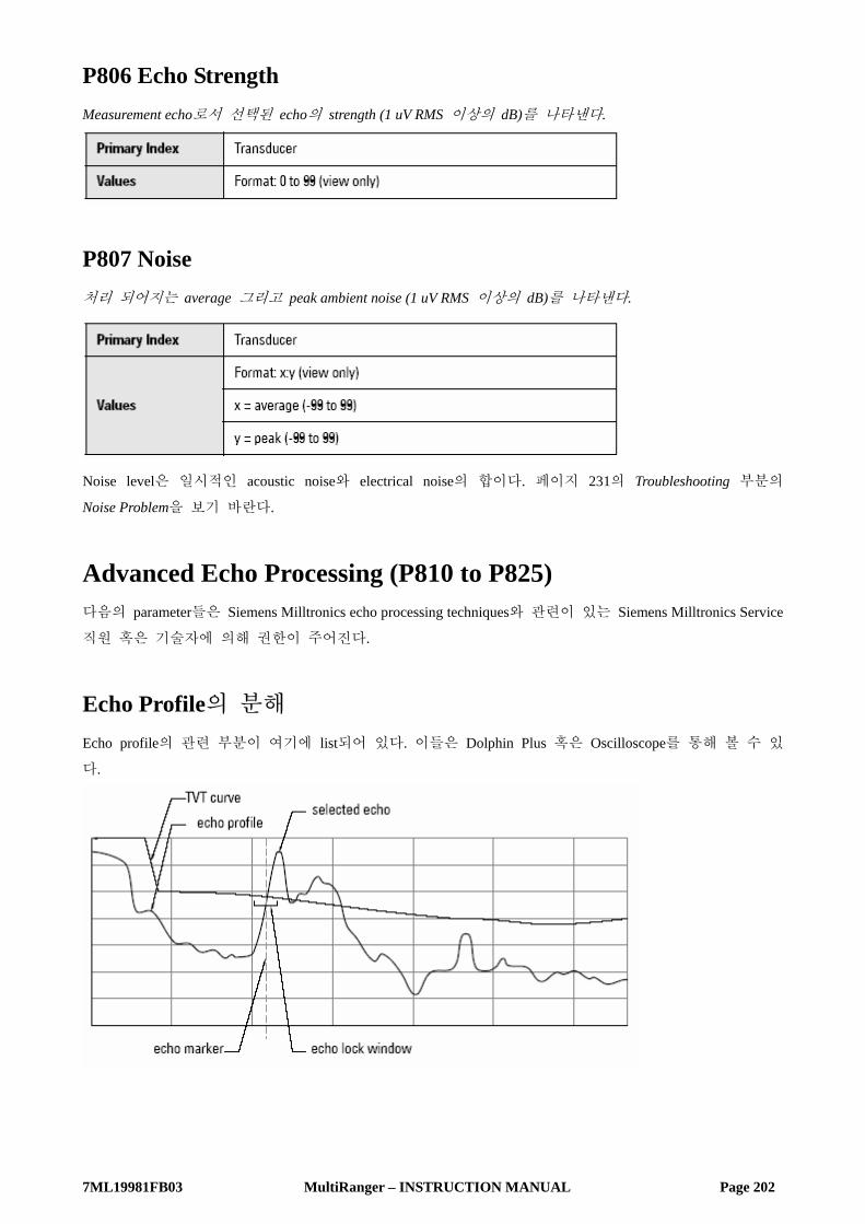
7ML19981FB03 MultiRanger – INSTRUCTION MANUAL Page 202
P806 Echo Strength Measurement echo로서 선택된 echo의 strength (1 uV RMS 이상의 dB)를 나타낸다.
P807 Noise 처리 되어지는 average 그리고 peak ambient noise (1 uV RMS 이상의 dB)를 나타낸다.
Noise level은 일시적인 acoustic noise와 electrical noise의 합이다. 페이지 231의 Troubleshooting 부분의
Noise Problem을 보기 바란다.
Advanced Echo Processing (P810 to P825) 다음의 parameter들은 Siemens Milltronics echo processing techniques와 관련이 있는 Siemens Milltronics Service
직원 혹은 기술자에 의해 권한이 주어진다.
Echo Profile의 분해 Echo profile의 관련 부분이 여기에 list되어 있다. 이들은 Dolphin Plus 혹은 Oscilloscope를 통해 볼 수 있
다.

7ML19981FB03 MultiRanger – INSTRUCTION MANUAL Page 203
P810 Scope Displays Oscilloscope 상에 display를 위해서 echo profile을 캡쳐한다.
이 기능은 Echo Processing changes의 영향을 monitor하는데 사용한다.
Oscilloscope를 Mother Board TP2 (Scope), TP5 (DCOM), TP6 (Sync)에 연결한다.
Note : Analog oscilloscope의 사용이 digital oscilloscope보다 좋다.
다음의 Scope Display의 어떠한 combination도 적용이 가능하다.
Scope Displays를 선택하는 두 가지 방법 :
Scrolling
1. Auxiliary Function symbol를 나타내기 위해서 READING 을 누른다.
2. Desired Reading display symbol에 접근하기 위해서 ARROW 버튼을 누른다.
3. Desired display symbol이 나타나는 것과 함께 ENTER 버튼을 누른다.

7ML19981FB03 MultiRanger – INSTRUCTION MANUAL Page 204
1/0 Values 선택적으로 0이 관계된 signal display를 OFF로 만드는 곳과 1이 display를 ON으로 만드는 곳에 four-digit
binary value은 입력될 수 있다.
1110=PCn_: • Echo Profiles, TVT Curve, and Echo Marker displays ON
• Echo Lock Window display OFF
Parameter 변경의 결과를 보기 위해 Transducer 를 누른 후에 Scope Displays를 사용한다. Repeatability
를 확인하기 위해서 여러 측정치를 취합하고 Echo Lock (P711) restrictions를 극복한다.
P815 Echo Time Filtered Process가 진행될 때의 Pulse의 전달로부터의 Time (in ms).
P816 Echo Time Raw Transmit pulse로부터 processed echo까지의 Time (in ms).
Profile Pointer (P817 to P825) 이 parameter들의 하나에 접근되어지면 scope display가 변한다 : Echo Lock Window가 Profile Pointer가 된다.
Profile Pointer는 선택된 parameter에 따라서 Profile에 관한 특정 Information을 얻기 위해서 Echo Profile상
에 어떤 Point로 옮겨지게 된다.
Profile Pointer가 특정 point로 옮겨지기 위해서는 원하는 값을 입력한다. 이는 받아들여질 수 있는 가장
가까운 Echo Profile point로 옮겨질 것이다.
선택적으로, Echo Profile을 따라서 Profile Pointer를 scroll 하려면 :
1. Auxiliary Function symbol을 나타내기 위해서 버튼을 누른다.
2. Profile Pointer를 개별적으로 왼쪽이나 오른쪽으로 옮기기 위해서는 혹은 버튼을 누른다.
3. Profile Pointer Parameter들이 빠져나가질 때, Scope Display는 자동적으로 Echo Lock Window를 포함하기
위해서 되돌려 변화된다.

7ML19981FB03 MultiRanger – INSTRUCTION MANUAL Page 205
P817 Profile Pointer Time Transmit pulse로부터 Profile Pointer까지의 Time (in ms).
P818 Profile Pointer Distance Transducer face 그리고 Profile Pointer 사이의 거리.
P819 Profile Pointer Amplitude Pointer position에서 Echo Profile의 크기 (in dB above 1uV).

7ML19981FB03 MultiRanger – INSTRUCTION MANUAL Page 206
P820 Algorithm Profile로부터 측정된 값을 생성하기 위해서 algorithm을 선택한다.
이는 Sonic Intelligence® echo selection에 근거한 algorithm을 선택하기 위해서 사용한다. P805 Echo
Confidence는 모든 level condition에서 가장 높은 confidence를 주는 algorithm을 결정하기 위해 사용한다.
잘못된 echo가 진행된다면, echo processing display를 관찰하고 대체할 수 있는 algorithm을 numeric value혹
은 아래와 같이 선택한다 :
1. Auxiliary symbol을 나타내기 위해서 MEASURE 버튼을 누른다.
2. 의도된 Reading Display symbol에 접근하기 위해서 ARROWS 버튼을 누른다.
3. 필요한 algorithm이 나타났을 때 ENTER 버튼을 누른다.

7ML19981FB03 MultiRanger – INSTRUCTION MANUAL Page 207
P821 Spike Filter False reading을 줄이기 위해서 echo profile 상에서 spike를 둔화시킨다.
Interference spikes가 long shot Echo Profile display 상에 있다면 P821을 사용한다.
P822 Narrow Echo Filter 특정 넓이의 Echo를 걸러낸다.
Transducer acoustic beam interference를 위해 이를 사용한다. Long shot Echo Profile로부터 제거되어지기 위한
false echoes의 넓이를 입력한다. 값을 키로 넣으면 가장 근접한 받아들여지는 값이 입력된다.

7ML19981FB03 MultiRanger – INSTRUCTION MANUAL Page 208
P823 Reform Echo Echo Profile에서의 불규칙한 peak를 제거한다.
Monitored surface가 평탄함에도 불구하고 기록되는 level에 요동이 있다면 monitoring solids (P002=2)일 때,
이 기능을 사용한다. 필요로 하는 Long shot Echo Profile smoothing의 양을 입력한다. 값의 입력 시, 가장
근접한 받아들여질 수 있는 값이 입력된다.
P825 Echo Marker Trigger 측정되는 값이 근거한 Primary Echo 상에서의 Point.
Echo Profile상에서 true echo의 leading edge에서 변화하기 쉬운 상승고로 인해 기록되는 material level이 약
하게 요동을 한다면 이 기능을 사용한다.
True echo로 표현되는 Echo Profile의 sharpest rising portion에서 Echo Lock Window가 Echo Profile에 교차하는
것을 (가로지르는 것을) 확인하기 위해서 값 (echo 높이의 %) 을 입력한다. 이 값은 50%로 미리 세팅되
어 있다.

7ML19981FB03 MultiRanger – INSTRUCTION MANUAL Page 209
Advanced TVT Adjustment (P830 to P835) 다음의 parameter들은 권한이 주어진 Siemens Milltronics Service personnel 혹은 Siemens Milltronics echo
processing techniques에 관계한 기술자를 위한 것이다.
Advanced TVT control은 오직 long shots에 적용이 된다.
P830 TVT Type 사용되는 TVT Curve를 선택한다.
모든 level conditions 하에서 highest confidence (P805)를 제공하는 TVT Type을 선택한다. 이 parameter는 주
의해서 사용해야 하며, bF 혹은 bLF Algorithm (P820)과 함께 TVT Slopes를 사용하지 않는다.
P831 TVT Shaper TVT shaper의 ON 혹은 OFF.
P832의 사용 전 그리고 후에 TVT Shaper를 ON 시킨다. True echo를 골라내기 위해 effect를 monitor 시키
는 동안 TVT Shaper를 ON 그리고 OFF 시킨다.
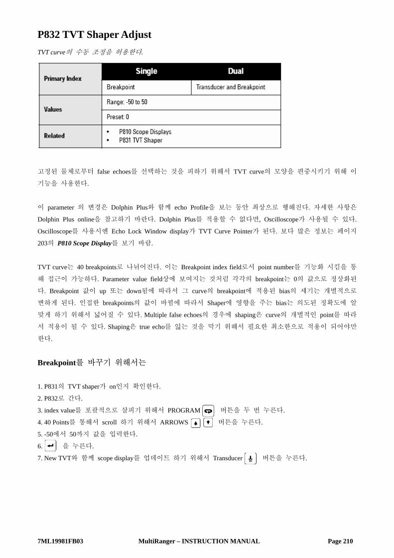
7ML19981FB03 MultiRanger – INSTRUCTION MANUAL Page 210
P832 TVT Shaper Adjust TVT curve의 수동 조정을 허용한다.
고정된 물체로부터 false echoes를 선택하는 것을 피하기 위해서 TVT curve의 모양을 편중시키기 위해 이
기능을 사용한다.
이 parameter 의 변경은 Dolphin Plus와 함께 echo Profile을 보는 동안 최상으로 행해진다. 자세한 사항은
Dolphin Plus online을 참고하기 바란다. Dolphin Plus를 적용할 수 없다면, Oscilloscope가 사용될 수 있다.
Oscilloscope를 사용시엔 Echo Lock Window display가 TVT Curve Pointer가 된다. 보다 많은 정보는 페이지
203의 P810 Scope Display를 보기 바람.
TVT curve는 40 breakpoints로 나뉘어진다. 이는 Breakpoint index field로서 point number를 기능화 시킴을 통
해 접근이 가능하다. Parameter value field상에 보여지는 것처럼 각각의 breakpoint는 0의 값으로 정상화된
다. Breakpoint 값이 up 또는 down됨에 따라서 그 curve의 breakpoint에 적용된 bias의 세기는 개별적으로
변하게 된다. 인접한 breakpoints의 값이 바뀜에 따라서 Shaper에 영향을 주는 bias는 의도된 정확도에 알
맞게 하기 위해서 넓어질 수 있다. Multiple false echoes의 경우에 shaping은 curve의 개별적인 point를 따라
서 적용이 될 수 있다. Shaping은 true echo를 잃는 것을 막기 위해서 필요한 최소한으로 적용이 되어야만
한다.
Breakpoint를 바꾸기 위해서는 1. P831의 TVT shaper가 on인지 확인한다.
2. P832로 간다.
3. index value를 포괄적으로 살피기 위해서 PROGRAM 버튼을 두 번 누른다.
4. 40 Points를 통해서 scroll 하기 위해서 ARROWS 버튼을 누른다.
5. -50에서 50까지 값을 입력한다.
6. 을 누른다.
7. New TVT와 함께 scope display를 업데이트 하기 위해서 Transducer 버튼을 누른다.

7ML19981FB03 MultiRanger – INSTRUCTION MANUAL Page 211
P833 TVT Start Min Echo Profile의 start 근처에서 false echoes를 무시하거나 true echo를 골라내기 위해서 TVT Curve height를 조
정하기 위해서 이 기능을 사용한다.
최소의 TVT Curve start point (1uV RMS 이상의 dB)를 입력한다.
이 기능은 증가된 Near Blanking (P800)은 의도된 측정 range보다도 길게 연장된다면 사용되어져야만 한다.
P834 TVT Start Duration Echo Profile의 start 근처에서 false echoes를 무시하거나 true echo를 골라내기 위해서 TVT Start Min과 결합
하여 이 기능을 사용한다.
TVT Start Min (P833) point로부터 TVT Curve baseline에까지 TVT Curve를 줄이기 위해서 time을 입력한다.
P835 TVT Slope Min TVT Curve의 중간 부분을 위해서 최소 slope (dB/s)를 입력한다.
slope 하강을 위해서 이 기능을 사용한다. 그리고 Echo Profile의 중간 부분에서 TVT Curve가 false echoes
의 위에 머무르는 것을 확인하기 위해 TVT Start Duration과 결합하여 이를 사용한다. 선택적으로, TVT
Type이 TVT Slopes (P830=6)로 세팅되어 있다면 preset은 2000이다.

7ML19981FB03 MultiRanger – INSTRUCTION MANUAL Page 212
Advanced Shot Adjustment (P840 to P852) 이 parameter들은 Siemens Milltronics Service personnel 만을 위한 것이다.
P840 Short Shot Number Transmit pulse 당 fire되는 short shots의 수.
P841 Long Shot Number Transmit pulse 당 fire된 long shots의 수를 입력한다.
이 값은 Maximum Process Speed (003)에 의해서 자동적으로 수정된다.
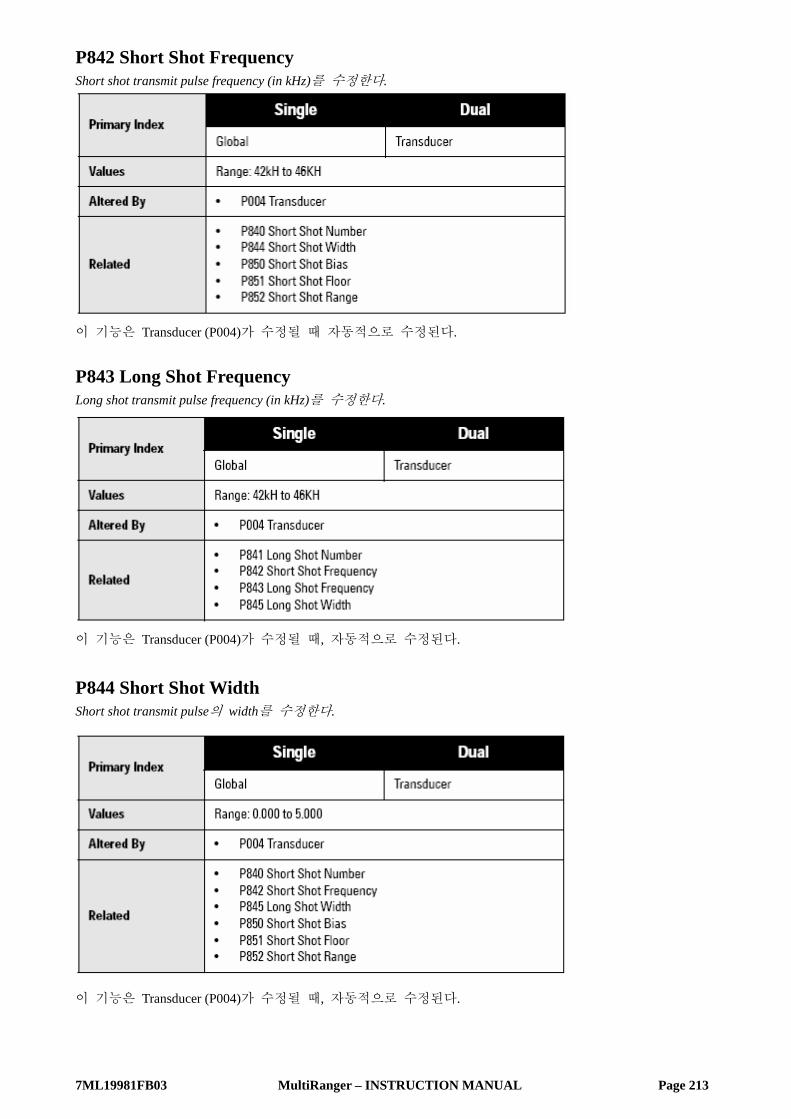
7ML19981FB03 MultiRanger – INSTRUCTION MANUAL Page 213
P842 Short Shot Frequency Short shot transmit pulse frequency (in kHz)를 수정한다.
이 기능은 Transducer (P004)가 수정될 때 자동적으로 수정된다.
P843 Long Shot Frequency Long shot transmit pulse frequency (in kHz)를 수정한다.
이 기능은 Transducer (P004)가 수정될 때, 자동적으로 수정된다.
P844 Short Shot Width Short shot transmit pulse의 width를 수정한다.
이 기능은 Transducer (P004)가 수정될 때, 자동적으로 수정된다.

7ML19981FB03 MultiRanger – INSTRUCTION MANUAL Page 214
P845 Long Shot Width Long shot transmit pulse의 width를 수정한다.
이 기능은 Transducer (P004)가 수정될 때 자동적으로 수정된다.
P850 Short Shot Bias Short와 Long shots이 같이 수치가 구해질 때 short shot echo의 경향으로 echo evaluation을 기울이기 위해
이 기능을 사용한다.
P851 Short Shot Floor Evaluation으로 여겨지는 short shot에서 얻어지는 최소의 echo strength를 입력한다.

7ML19981FB03 MultiRanger – INSTRUCTION MANUAL Page 215
P852 Short Shot Range Short shot echoes를 사용하여 측정되는 unit에서의 maximum distance를 입력한다.
이 기능은 Transducer (P004)가 수정될 때, 자동으로 수정된다.
Test (P900 to P913) Test Parameters는 Siemens Milltronics Service personnel에 의해서 사용되는 것이 의도된다.
P900 Software Revision Number EPROM Rev. #.를 본다.
P901 Memory MultiRanger memory test를 activate하기 위해서 ENTER를 누른다.

7ML19981FB03 MultiRanger – INSTRUCTION MANUAL Page 216
P902 Watchdog Watchdog timer를 테스트하기 위한 CPU를 infinite loop에 넣기 위해서 ENTER를 누른다.
성공적인 완성 (10 seconds)일 때 Run mode를 입력하고 MultiRanger는 reset된다. 전원이 끊어진다면
Programming이 유지되고 unit이 응답한다.
P903 Display Display test를 activate하기 위해서 ENTER를 누른다.
모든 LCD 부분과 symbol들은 임시적으로 보여진다.
P904 Keypad ENTER를 누르고, 다음의 순서대로 각각의 keypad key를 누른다 :
각각의 키가 눌러짐에 따라, 관계된 keypad number가 보여진다. 성공적인 테스트가 행해지면 PASS가 나
타난다. FAIL은 key가 순서에 어긋나게 되거나 programmer keypad가 오작동 한다면 나타나게 된다.
P905 Transmit Pulse Transducer terminal에 연결된 Oscilloscope와 함께 Transmit pulse를 monitor 하기 위해서 이 기능은 사용될
수 있다.
입력된 frequency에서 반복되는 Transmit pulse를 Transducer에 공급하거나 또는 Point Number를 display 되
게 하기 위해서 Transducer operating frequency를 보여주기 위해서 ENTER를 누른다.
P906 RS-232 Port RJ-11 상에서의 RS-232 port를 테스트 하기 위해서 ENTER를 누른다.
외부 계기는 TEST를 위해서 RS-232 port에 연결해야만 한다. 성공적인 완수라면 PASS가 보여지고, 그렇
지 않다면 FAIL이 보여질 것이다.

7ML19981FB03 MultiRanger – INSTRUCTION MANUAL Page 217
P908 Scanner Transmitter의 firing 동안 scanner relay가 순환하게 하기 위해서 Enter를 누른다.
양 Transducers가 활성화되어 있는 것을 확인하기 위해서 이 parameter를 사용한다.
P910 Toggle Relays 직접적으로 relays를 energize 그리고 de-energize 하는데 사용한다.
relay number를 입력하고 필요한 energized 와 de-energized 사이에서 toggle한다. 즉시 모든 relay를 toggle하
기 위해서 0을 입력한다.
P119=0과 함께 오직 relay에 적용한다. Relay contacts가 opening 되고 그리고 closing 되는 것을 확정하기
위해서 이 parameter를 사용한다.
Programming이 확인되었음에도 기대되는 결과를 P119가 주지 못할 때 이 기능은 도움을 준다.
P911 mA Output Value mA output의 현재의 값을 나타내기 위해 이 parameter에 접근한다.
추가적으로 이 기능은 의도된 값을 입력하는 사용되어질 수 있다. mA output은 프로그램된 어떠한 제한
에도 관계없이 입력된 값을 즉시 취한다.
P912 Transducer Temperature ℃에서 temperature를 나타내기 위해서 이 기능을 사용한다. (연결된 transducer에 의해 monitor)
transducer가 내부 온도 센서가 설치되어 있지 않다면 ERR 는 나타나지 않는다.

7ML19981FB03 MultiRanger – INSTRUCTION MANUAL Page 218
P913 Sensor Temperature ℃의 온도를 나타내기 위해서 이 parameter에 접근한다.
TS-3이 연결되어 있지 않다면 OPEn은 나타나지 않는다.
P914 mA Input [MR 200] mA input value를 나타내기 위해서 이 기능을 사용한다.

7ML19981FB03 MultiRanger – INSTRUCTION MANUAL Page 219
Measurement (P920 to P927) 이 parameters는 Run mode에서 적용이 가능하고 Programming을 확인하기 위해서 사용한다. 페이지 22의
Run mode의 Readings를 보기 바람.
이 parameter의 각각에서 보여지는 range와 값은 선택된 Operation에 좌우된다. 각각의 operation을 위한
reading은 다음에 리스트되어 있다.
Run Mode에 접근하려면 1. 계기가 Run mode에 있는지 확인한다.
2. 버튼을 누른다. Auxiliary Reading field는 underscores P___가 된다.
3. Parameter number를 입력한다. Field는 특정 parameter의 값으로 변한다.
이 parameter들은 simulation mode에 또한 적용이 가능하다. 페이지 83의 simulation direction과 rate를 컨트
롤하는 방법을 위해서 Testing the Configuration 부분을 보기 바람.
P920 Reading Measurement 모든 programming이 적용된 후에 final reading에 상응한다.
다음의 기능은 오직 MultiRanger 200에만 적용됨을 기억하기 바람 : Difference, Average, OCM, and Pump
Totalizer.
일반적으로 P920=Reading x P060 + P061임을 의미한다.
Operation에 의한 Reading Measurement

7ML19981FB03 MultiRanger – INSTRUCTION MANUAL Page 220
P921 Material Measurement Empty (P006)과 monitored surface 사이에서 unit (P005) 혹은 Span (P007)의 % 상에서의 거리.
P922 Space Measurement Monitored surface 그리고 Span (P007)사이의 거리.
P923 Distance Measurement Monitored surface와 transducer face 사이의 거리.
P924 Volume Measurement [MR 200] Max Volume (P051) 혹은 Max Volume의 % 에서의 계산된 vessel capacity.
Volume Measurement는 오직 MultiRanger 200에만 적용됨을 기억하기 바람.

7ML19981FB03 MultiRanger – INSTRUCTION MANUAL Page 221
P925 Flow Measurement [MR 200] Max Flow (P604) units 혹은 Max Flow의 %에서의 계산된 flowrate.
Flow Measurement는 오직 MultiRanger 200에만 적용됨을 기억하기 바람.
P926 Head Measurement [MR 200] Head 상응한다. (Units (P005)혹은 Span (P007)의 % 상에서 Zero Head (P605)로부터 monitored surface까지의
거리)
Head Measurement는 오직 MultiRanger 200에만 적용됨을 기억하기 바람.
P927 Distance Measurement Surface와 Transducer face 사이의 거리.
Distance information이 percent 에서 요구되지 않는다면 P923을 사용한다.

7ML19981FB03 MultiRanger – INSTRUCTION MANUAL Page 222
Master Reset (P999) 이 기능은 모든 parameter를 원래의 값으로 reset 한다.
이 기능을 임의의 parameter 값을 bench test 동안에 사용하거나 software의 업그레이드 후에 사용된다면
초기의 programming 전에 사용한다. 다음의 Master Reset, complete reprogramming을 필요로 한다.
Master Reset을 수행하기 위해서, P999에 접근하여 CLEAR를 누른다. Reset이 끝날 때까지 C.ALL이 나타난
다.
Dual point units에서 양 point는 index를 00으로 세팅하거나 CLEAR key를 누름에 의해서 동시에 reset할 수
있다.
Caution : 이 기능을 사용시에 주의하여야 한다. 모든 points를 위한 모든 Data는 reset될 것이다. 편의를
위해서 re-enter를 원하는 값을 record 하는 것을 확인해야 한다.

7ML19981FB03 MultiRanger � INSTRUCTION MANUAL Page 223
mm
mm
m
Appendix A
: Index Types
General Appendix A: Index Types
Index typesName Description # of indexes
Global This parameter applies to the entire unit n/a
View only This parameter can not be set, only viewed n/a
Breakpoint Indexed by breakpoint Parameter dependent
Dimension Indexed by PMD dimension up to 7
Discrete Input Indexed by discrete input 2
Echo Profile Indexed by stored echo profile 10
Level Point1
1. MultiRanger 100: The two level points are: Transducer One and Trans-ducer Two.Level point typically has 1 index in Single Point Mode (standard), and 2 indexes in Dual Point Mode (optional).MultiRanger 200: The three level points are: transducer 1, transducer 2, and the calculated point which can be difference (P001=4) or average (P001=5).Level point typically has 1 index in Single Point Mode (standard), and 2 indexes in Dual Point Mode (optional). A third index is available in both modes when Operation (P001) is set for DPD (P001=4) or DPA (P001=5).
Indexed by level point 1, 2 or 3
mA input1 Indexed by mA input 1
mA output1 Indexed by mA output 0 or 2
Comm. Port Indexed by communications port 2
Relay Indexed by relay 3 or 6
Transducer2
2. MultiRanger 200: The number of indexes available in Single Point Mode (standard) is typically 1, but can be expanded to 2 if Operation (P001) is set for DPD (P001=4) or DPA (P001=5).In Dual Point Mode (optional), the number of available indexes isalways 2.
Indexed by transducer 1 or 2
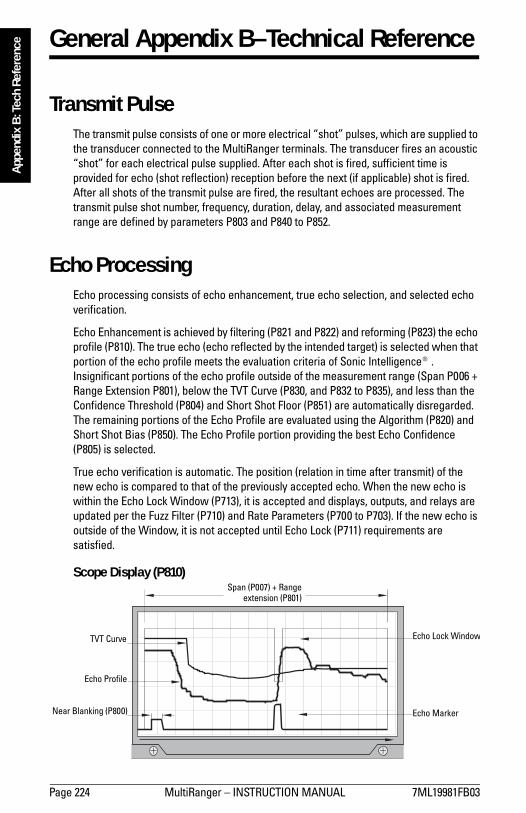
Page 224 MultiRanger � INSTRUCTION MANUAL 7ML19981FB03
mm
mm
m
App
endi
x B
: Tec
h Re
fere
nce General Appendix B–Technical Reference
Transmit PulseThe transmit pulse consists of one or more electrical �shot� pulses, which are supplied to the transducer connected to the MultiRanger terminals. The transducer fires an acoustic �shot� for each electrical pulse supplied. After each shot is fired, sufficient time is provided for echo (shot reflection) reception before the next (if applicable) shot is fired. After all shots of the transmit pulse are fired, the resultant echoes are processed. The transmit pulse shot number, frequency, duration, delay, and associated measurement range are defined by parameters P803 and P840 to P852.
Echo ProcessingEcho processing consists of echo enhancement, true echo selection, and selected echo verification.
Echo Enhancement is achieved by filtering (P821 and P822) and reforming (P823) the echo profile (P810). The true echo (echo reflected by the intended target) is selected when that portion of the echo profile meets the evaluation criteria of Sonic Intelligence®. Insignificant portions of the echo profile outside of the measurement range (Span P006 + Range Extension P801), below the TVT Curve (P830, and P832 to P835), and less than the Confidence Threshold (P804) and Short Shot Floor (P851) are automatically disregarded. The remaining portions of the Echo Profile are evaluated using the Algorithm (P820) and Short Shot Bias (P850). The Echo Profile portion providing the best Echo Confidence (P805) is selected.
True echo verification is automatic. The position (relation in time after transmit) of the new echo is compared to that of the previously accepted echo. When the new echo is within the Echo Lock Window (P713), it is accepted and displays, outputs, and relays are updated per the Fuzz Filter (P710) and Rate Parameters (P700 to P703). If the new echo is outside of the Window, it is not accepted until Echo Lock (P711) requirements are satisfied.
Scope Display (P810)
TVT Curve
Echo Profile
Near Blanking (P800) Echo Marker
Echo Lock Window
Span (P007) + Rangeextension (P801)

7ML19981FB03 MultiRanger � INSTRUCTION MANUAL Page 225
mm
mm
m
Appendix B
: Tech Reference
Dolphin Plus Display
Distance CalculationTo calculate the transducer to material level (object) distance, the transmission medium (atmosphere) sound velocity (P653) is multiplied by the acoustic transmission to reception time period. This result is divided by 2 to calculate the one way distance.
Distance = Sound Velocity x Time / 2
The Reading displayed is the result of performing any additional modification to the calculated distance (as determined by Operation P001, Units P005, Volume Conversion, P050 to P054, Reading, P060 to P063, OCM, P600 to P611, and/or Totalizer P622 to P633 parameters).
Sound VelocityThe sound velocity of the transmission medium is affected by the type, temperature, and vapor pressure of the gas or vapor present. As preset, the MultiRanger assumes the vessel atmosphere is air at 20°C (68°F). Unless altered, the sound velocity used for the distance calculation is 344.1 m / s (1129 ft / s).
Variable air temperature is automatically compensated when a Siemens Milltronics ultrasonic / temperature transducer is used. If the transducer is exposed to direct sunlight, use a sunshield or a separate TS-3 temperature sensor.
Also, if the temperature varies between the transducer face and the liquid monitored, use a TS-3 temperature sensor (submerged in the liquid) in combination with an ultrasonic / temperature transducer. Set Temp Source (P660) for both, to average the transducer and TS-3 measurements.
Atmosphere composition other than air can pose a challenge for ultrasonic level measurement. However, excellent results may be obtained by performing a Sound Velocity Calibration (P651) if the atmosphere is homogeneous (well mixed), at a fixed temperature, and under consistent vapor pressure.
The MultiRanger automatic temperature compensation is based on the sound velocity / temperature characteristics of �air� and may not be suitable for the atmosphere present.
Cursor
Echo Marker
TVT Curve
Echo Profile
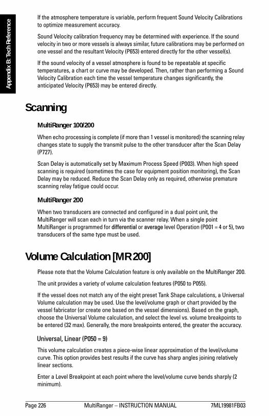
Page 226 MultiRanger � INSTRUCTION MANUAL 7ML19981FB03
mm
mm
m
App
endi
x B
: Tec
h Re
fere
nce If the atmosphere temperature is variable, perform frequent Sound Velocity Calibrations
to optimize measurement accuracy.
Sound Velocity calibration frequency may be determined with experience. If the sound velocity in two or more vessels is always similar, future calibrations may be performed on one vessel and the resultant Velocity (P653) entered directly for the other vessel(s).
If the sound velocity of a vessel atmosphere is found to be repeatable at specific temperatures, a chart or curve may be developed. Then, rather than performing a Sound Velocity Calibration each time the vessel temperature changes significantly, the anticipated Velocity (P653) may be entered directly.
ScanningMultiRanger 100/200
When echo processing is complete (if more than 1 vessel is monitored) the scanning relay changes state to supply the transmit pulse to the other transducer after the Scan Delay (P727).
Scan Delay is automatically set by Maximum Process Speed (P003). When high speed scanning is required (sometimes the case for equipment position monitoring), the Scan Delay may be reduced. Reduce the Scan Delay only as required, otherwise premature scanning relay fatigue could occur.
MultiRanger 200
When two transducers are connected and configured in a dual point unit, the MultiRanger will scan each in turn via the scanner relay. When a single point MultiRanger is programmed for differential or average level Operation (P001 = 4 or 5), two transducers of the same type must be used.
Volume Calculation [MR 200]Please note that the Volume Calculation feature is only available on the MultiRanger 200.
The unit provides a variety of volume calculation features (P050 to P055).
If the vessel does not match any of the eight preset Tank Shape calculations, a Universal Volume calculation may be used. Use the level/volume graph or chart provided by the vessel fabricator (or create one based on the vessel dimensions). Based on the graph, choose the Universal Volume calculation, and select the level vs. volume breakpoints to be entered (32 max). Generally, the more breakpoints entered, the greater the accuracy.
Universal, Linear (P050 = 9)
This volume calculation creates a piece-wise linear approximation of the level/volume curve. This option provides best results if the curve has sharp angles joining relatively linear sections.
Enter a Level Breakpoint at each point where the level/volume curve bends sharply (2 minimum).

7ML19981FB03 MultiRanger � INSTRUCTION MANUAL Page 227
mm
mm
m
Appendix B
: Tech ReferenceFor combination curves (mostly linear but include one or more arcs), enter numerous breakpoints along the arc, for best volume calculation accuracy.
Universal, Curved [MR 200]Please note that the Universal, Curved feature is only available on the MultiRanger 200.
Set P050 = 10
This calculation creates a cubic spline approximation of the level/volume curve, providing best results if the curve is non-linear, and there are no sharp angles.
Select at least enough breakpoints from the curve to satisfy the following:
� two breakpoints very near the minimum level� one breakpoint at the tangent points of each arc� one breakpoint at each arc apex� two breakpoints very near the maximum levelFor combination curves, enter at least two breakpoints immediately before and after any sharp angle (as well as one breakpoint exactly at the angle) on the curve.
Flow CalculationPlease note that the Flow Calculation feature is only available on the MultiRanger 200.
The MultiRanger provides numerous OCM flow calculation features (P600 to P611).
If the PMD (primary measuring device) does not match any of the eight preset PMD calculations, or if a PMD is not used, select a Universal Volume calculation. Use the head/flow graph or chart provided by the PMD fabricator (or create one based on the PMD or channel dimensions).
Based on the graph, choose the Universal Flow calculation, and select the head versus flow breakpoints to be entered (32 max). Generally, the more breakpoints entered, the greater the flow calculation accuracy.

Page 228 MultiRanger � INSTRUCTION MANUAL 7ML19981FB03
mm
mm
m
App
endi
x B
: Tec
h Re
fere
nce Universal, Linear [MR 200]
Please note that the Universal, Linear feature is only available on the MultiRanger 200.
Set P600 = 4.
This flow calculation creates a piece-wise linear approximation of the head/flow curve. This option provides best results if the curve has sharp angles joining relatively linear sections.
Enter a Head Breakpoint at each point where the head/flow curve bends sharply (2 minimum). For combination curves (mostly linear but include 1 or more arcs), enter numerous breakpoints along the arc, for best flow calculation accuracy.
See also Typical Flow Characterization on page 81.
Universal, Curved [MR 200]Please note that the Universal, Curved feature is only available on the MultiRanger 200.
This calculation creates a cubic spline approximation of the head/flow curve, providing best results if the curve is non-linear, and there are no sharp angles.
Select at least enough breakpoints from the curve to satisfy the following:
� two breakpoints very near the minimum head� one breakpoint at the tangent points of each arc� one breakpoint at each arc apex� two breakpoints very near the maximum head

7ML19981FB03 MultiRanger � INSTRUCTION MANUAL Page 229
mm
mm
m
Appendix B
: Tech Reference
For combination curves, enter at least 2 breakpoints immediately before and after any sharp angle (as well as 1 breakpoint exactly at the angle) on the curve. For more information, go to Typical Flow Characterization on page 81.
Maximum Process SpeedThe MultiRanger�s ability to respond to material level changes is designed to exceed even the most demanding installation requirements.
The Maximum Process Speed setting automatically presets various parameters affecting the MultiRanger response to material level changes as follows:
If any of these parameters are independently altered, a Maximum Process Speed (P003) parameter alteration automatically resets the independently altered value.
Slower Maximum Process Speed (P003) provides greater measurement reliability. Faster, independently set Max Fill (P700) and Max Empty (P701). Rates may be impeded by Echo Lock (P711), Scan Delay (P727), and Shot Delay (P728) values.
Parameter Values Dependent on Maximum Process Speed (P003)
(units) 1 (slow) 2 (medium) 3 (fast)
P070 Failsafe Timer (min) 100 10 1
P700 Max Fill Rate (m/min) 0.1 1 10
P701 Max Empty Rate (m/min) 0.1 1 10
P702 Filling Indicator (m/min) 0.01 0.1 1
P703 Emptying Indicator (m/min) 0.01 0.1 1
P704 Rate Filter (option) 4 2 2
P710 Fuzz Filter (% of Span) 100 50 10
P713 Echo Lock Window (per P701 / P702 and time since last valid measurement)
P727 Scan Delay (seconds) 5 5 3
P841 Long Shot Number 10 5 2

7ML19981FB03 MultiRanger – INSTRUCTION MANUAL Page 230
General Appendix C : Troubleshooting
Note : Parameter의 많은 부분과 여기에 서술된 techniques는 Ultrasonic technologies과 Siemens Milltronics
echo processing software의 응용지식을 필요로 한다. 주의 깊게 이 information을 사용하기 바람.
Setup이 너무 혼란스럽다면 P999를 사용하여 reset하고 다시 시작하기 바람.
Common Problems Chart
Symptom Cause Action Display에 아무것도 나타나지 않고, transducer가 pulsing 하지 않을 경우
전원의 끊김 전원, wiring, 전원퓨즈를 확인한다.
Programmer에 응답이 없을 경우
적외선 interface가 간섭을 받거나, 결점이 있는 Programmer
Programmer 사용을 체크한다 : 상위target에 point된 faceplate으로부터15cm (6”).
Short 그리고 tb:(#)가 나타날 때
Transducer cable의 단락 혹은 가리켜진 terminal block number에서의 결점이 있는 transducer
필요한 경우 수리 혹은 교체
Transducer가 연결되어 있지 않거나 거꾸로 연결이 되어 있을 때
나타나는 terminal blocks의 연결을체크한다.
Open 그리고 tb:(#)가 나타날 때 Transducer cable이 open되어 있거나 가리켜진 terminal block number에서의 결점이 있는 transducer.
필요한 경우 수리 혹은 교체
Material에 있어 Transducer의 다시배치 혹은/그리고 재조정. LOE 가 나타날 때 약하거나 혹은 존재하지 않는 echo Measurement Difficulties를 계속한다.
잘못된 선택의 transducer (P004) Transducer type을 확인하고 값을 다시 입력한다.
Two wire 방법으로 Transducer가 연결 시
White와 Shield를 함께 묶지 않는다. 모든 three terminal blocks을 사용한다.
Error 그리고 tb:(#)가 나타날 때
Transducer가 거꾸로 연결 시 Terminal block에서 black과 white wire를 바꾼다.
EEEE가 나타날 때 4 혹은 5 characters에 있어 나타내기에 너무 큰 값.
보다 큰 units (P005)를 선택하거나, lower Convert Reading (P061)을 선택한다.

7ML19981FB03 MultiRanger – INSTRUCTION MANUAL Page 231
판독 값이 material level이 평탄한데도 불구하고 요동이 있을 때 (혹은 이의 역)
부정확한 측정 stabilization
Maximum Process Speed (P003)을 수정하거나 damping (P704). Maximum Process Speed를 보기바람. Material level 혹은 물체에 transducer를 재위치 혹은/그리고 재배치 한다. Measurement Difficulties 이하로 나아간다.
판독 값이 실제의 material level에 관계없이 고정되었을 때
Transducer acoustic beam이 간섭을 받거나 standpipe가 너무 좁을 때, Transducer의 울림현상 (100%를 넘게 읽는다.)
Transducer Ringing을 보기 바람.
기록된 material level이 항상 같은 양으로 정확하지 않다
Level operation에 있어 정확하지 않은 Empty reference.
Empty (P006), Reading Offset (P063), Offset Calibration (P650), Offset Correction (P652)를 보기바람. Built-in temperature sensor 혹은 TS-3 temperature sensor와 함께 Transducer를 사용한다. Level이 transducer에 가까워질수록
측정 정밀도가 향상된다. Distance Calculation에 있어 부정확한 Sound Velocity를 사용
Sound Velocity를 본다.
Material에 있어 Transducer의 다시배치 혹은/그리고 재조정. 판독 값이 material level과 약간의 혹
은 아무런 관계없이 이상할 때 True echo가 너무 약하거나 Wrong echo가 진행될 때
Noise parameter를 체크한다. Noise Problems를 참고바람.
Noise Problems 부정확한 판독 값은 application에 있어 acoustic 혹은 electrical의 noise problem의 결과일 수 있다.
Input에서 Ultrasonic receiver에 나타나는 noise는 P807에 의해서 보여짐으로 결정될 수 있다. Display는
##:##를 읽으며 첫 번째 수는 평균 noise이며, 두 번째 수는 가장 심한 noise이다. 일반적으로 가장 유용
한 값은 평균 noise이다.
Transducer가 매달리지 않은 noise는 5dB 이하이다. 이는 noise floor라고도 불린다. Transducer가 매달린 값
이 5dB 보다 크다면, signal processing problems가 발생할 수 있다. High noise는 측정될 수 있는 maximum
distance를 줄인다. Noise와 maximum distance 사이의 정확한 관계는 Transducer type과 측정되는 material에
따라 영향을 받는다. 20dB 보다 큰 평균 noise level은 거리가 Transducer에 있어 maximum보다 짧지 않다
면 문제의 원인이 될 수 있다.

7ML19981FB03 MultiRanger – INSTRUCTION MANUAL Page 232
Determine the Noise Source MultiRanger로부터 Transducer를 분리한다. 만약 측정되는 noise가 5dB 이하라면, 계속한다. 만약 5dB 이
상이라면 아래의 Non-Transducer Noise Sources로 간다.
1. MultiRanger에 Transducer의 shield wire 만을 연결한다. 측정 noise가 5dB 이하라면, 다음 단계를 계속한
다. Noise가 5dB 이상이라면 Common Wiring Problems로 간다.
2. MultiRanger에 White and Black Transducer wire를 연결한다. Average noise를 기록한다.
3. Transducer의 positive wire를 제거한다. Average noise를 기록한다.
4. Positive wire를 재 연결하고 negative wire를 제거한다. Average noise를 기록한다.
아래의 table을 사용할 때, 알맞은 다음 단계를 결정한다. Higher, Lower 그리고 unchanged terms는 이전
steps에서 기록되는 noise를 참고한다.
이는 단지 guideline이다. 제공되는 solution이 문제를 해결하지 못할 때에는 역시 다른 방법을 시도해도
좋다.
Acoustical Noise 문제가 acoustical인지를 확실하게 알아보려면, Transducer의 표면에 여러 겹의 cardboard를 설치한다. 만약
noise가 줄어든다면 이 noise는 확실하게 acoustical 한 것이다.
Non-Transducer Noise Sources Noise의 monitoring 동안에 개별적으로 MultiRanger로부터 input과 output cable을 제거한다. Cable의 제거가
noise를 줄인다면, cable은 인접한 electrical equipment로부터 noise가 나아질 수 있다. Low voltage cables가
high voltage cables 혹은 variable speed drives에서 electrical noise generators 근처에서 작동되지 않는지를 체크
한다.

7ML19981FB03 MultiRanger – INSTRUCTION MANUAL Page 233
모든 다른 옵션이 사용되지 않았다면 Filtering cable은 옵션이지만 추천되지는 않는다.
MultiRanger는 variable speed drive와 같은 heavy industrial equipment 근처에서 작동하도록 디자인되어 있다.
그러므로, 이는 high voltage wire 혹은 switch gear 근처에 위치하지 않아야 한다.
Electronics를 다른 위치로 옮기도록 시도해 본다. 때때로 이러한 noise source로부터의 단지 몇 m 정도의
위치 변경은 문제를 해결 할 수도 있다. Electronics의 shielding은 역시 하나의 옵션이 될 수 있지만 이는
마지막 방책이다. 적당한 shielding은 비용이 많이 들며 알맞게 설치하는 것이 어렵다. – shielding box는
MultiRanger electronics를 완전히 둘러싸야 하며 모든 wire들은 접지된 metal 도관을 통해서 box에 가져와
져야 된다.
Common Wiring Problems • Transducer shield wire는 electronics 끝에 연결이 되어야만 한다. 어떠한 다른 곳에도 접지하지 말 것.
• Transducer shield wire를 white wire에 연결하지 말 것
• 노출된 Transducer shield wire는 가능한 짧아야 한다.
• Transducer에 의해 제공된 wire와 고객에 의해 설치된 연장 wire 사이의 연결은 접지된 metal junction box
에서 행해져야 한다.
Siemens Milltronics Transducer에서 white wire는 negative이며 black wire는 positive이다. 연장선이 다르게 색
칠이 되어 있다면, wiring이 일치하게 연결이 되었는지 확인한다.
연장선은 shielded twisted pair이어야 한다. 오래된 MultiRanger 제품은 noise를 줄이는 목적으로 co-axial
cable을 사용하는 것을 추천한다. Shielded twisted pair를 사용한다. Specifications를 위한 installation section
부분을 참고하기 바람.
Reducing Electrical Noise • Transducer cable은 high voltage 혹은 전류가 흐르는 다른 cable과 평행하게 가동되지 않음을 확인.
• variable speed drives처럼 noise generator로부터 떨어지게 Transducer를 옮긴다.
• Transducer cable을 접지된 metal conduit에 둔다.
• noise source를 걸러낸다.
Reducing Acoustical Noise • Transducer를 noise source로부터 멀리 옮긴다.
• stilling well을 사용한다.
• Transducer와 mounting surface 사이에 rubber 혹은 foam bushing 혹은 gasket을 설치한다.
• noise source를 재 위치시키거나 격리시킨다.
• noise의 주파수를 바꾼다. MultiRanger는 25KHz와 65KHz 사이에서 noise에 민감하다.

7ML19981FB03 MultiRanger – INSTRUCTION MANUAL Page 234
Measurement Difficulties Failsafe Timer (P070)가 measurement difficulty로 인해서 만료가 된다면 LOE는 마지막에 알려진 reading과
함께 선택적으로 반짝인다. 드문 경우로 MultiRanger는 false echo를 추적하여 고정된 혹은 틀린 reading을
기록한다.
Flashing LOE Display Echo confidence가 P805 Echo Confidence에 세팅된 threshold 값 이하일 때 echo (LOE) display의 loss가 나타
난다.
LOE가 일어나는 경우 : • echo를 잃었거나 주변 noise 이상에서 echo가 보여지지 않을 때. Low echo confidence (P805)와 low echo
strength (P806)을 참고 바람.
• 두 가지 echo가 차이점을 내기에 너무 비슷하다면. Low echo confidence (P805)와 low echo strength (P806)
을 참고 바람.
LOE가 보여진다면, 다음을 체크한다 : • 모니터 되는 surface가 transducer maximum range의 이내에 있는지
• Transducer model (P004)가 사용되는 Transducer와 매치되는지
• Transducer가 알맞게 위치하고 조정되어 있는지
• Transducer가 침수 shield없이 침수되어 있지는 않은지
Adjust Transducer Aiming Range, mounting, aiming을 위해서 Transducer manual을 참고한다. 최적의 수행을 위해서 measurement range
이내에서 모든 material level을 위한 최상의 Echo Confidence (P805)와 Echo Strength (P806)을 제공하기 위해
서 Transducer aiming을 변경한다.
Echo를 체크하는 가장 효율적인 방법은 Dolphin Plus software를 이용하는 것이다.

7ML19981FB03 MultiRanger – INSTRUCTION MANUAL Page 235
Run mode에서의 Echo Confidence를 나타내려면 버튼을 누르고 4초간 유지한다.
Program mode에서 Echo Confidence를 나타내기 위해서 Echo Confidence (P805) parameter로 접근한다.
각각의 aiming 조정 후에 나타나는 값을 업데이트 하려면..
를 누른다. (stability를 확인하기 위해서 다섯 번 혹은 그 이상 그리고 echo lock P711을 회복하기 위
해)
Increase Failsafe Timer Value Failsafe operation이 큰 값으로 인해서 처리되지 않았다면 Failsafe Timer (P070)의 값을 증가시킨다.
LOE가 짧은 시간 동안 보여질 때만 이를 시도한다.
Install a Transducer with a Narrow Beam 때때로 vessel의 side로부터의 간섭 echo는 MultiRanger가 일정하고 부정확한 level을 이어가는 원인을 제
공한다. 이런 경우 long range (narrow beam) Transducer를 설치를 시도하고, 새로운 Transducer model (P004)
를 입력한다. 그리고 필요하다면 aiming과 frequency를 다시 최적화시킨다.
이런 문제를 해결하기 위한 Transducer의 선택 전에 본사의 기술진과 연락을 취하기 바람.
Use Dolphin Plus to Debug Echo 보다 접은 Beam Transducer를 적용할 수 없다면, live sonic profiles를 보기 위해서 Dolphin Plus를 사용하고
Advanced Echo Processing parameter를 위한 조정을 한다.
Dolphin Plus를 가지고 있지 않다면 oscilloscope를 연결하여 같은 parameter를 조정하기 위한 hand
programmer를 사용하기 바란다.
Fixed Reading Transducer에서 material surface의 거리에 관계없이 판독 값이 고정되어 있다면, 다음을 확인한다.
1. Transducer acoustic beam이 장애물에 자유로운지
2. Transducer가 알맞게 조준되어 있는지
3. Transducer가 어떠한 metal 물체와 접촉되어 있지는 않은지
4. MultiRanger가 작동되고 있는 동안에 Material mixer가 작동되는지. 만약에 정지되어 있다면 mixer의 날
이 Transducer 하에서 정지되지 않았는지 확인한다.
Obstructions in the Sound Beam Acoustic beam obstruction을 체킹하고 Transducer를 재위치 시킨다.
장애물이 제거되거나 피해지지 않는다면 장애물에 의해 반사되는 sound에 의해 생기는 Echo Confidence
를 줄이기 위해 Time Varying Threshold (TVT) Curve를 조정한다. TVT curve를 조정하기 위해서는 Dolphin
Plus를 사용한다. 혹은 필요로 하는 parameter를 조정하려면 oscilloscope와 hand programmer를 사용한다.

7ML19981FB03 MultiRanger – INSTRUCTION MANUAL Page 236
Nozzle Mountings Transducer가 올려져서 설치되어 있거나 nozzle에 있다면, 안쪽이나 혹은 open end의 burrs (돌기)나 용접부
위를 부드럽게 한다. 만약 문제가 지속된다면 보다 큰 지름 혹은 짧은 길이의 nozzle을 설치하고 바닥
끝의 안쪽을 비스듬히 하고 또는 45° 각도에서 nozzle의 open end를 cut 한다.
완전한 mounting instructions를 위해서 Transducer manual를 보기 바람.
ST-series와 XPS-10 Transducer는 plastic conduit / unit에 의해서 제공된 Flange adapter를 사용한다.
Mounting hardware가 너무 조여졌다면, 느슨하게 해준다. 지나친 조임은 Transducer의 공명 특성에 변화시
키며 문제를 유발시킬 수 있다.
Set the MultiRanger to Ignore the Bad Echo 이전의 조치가 문제점을 해결하지 못한다면 false echo는 무시되어야만 한다.
Echo가 Transducer에 근접해 있다면
MultiRanger로부터 변화가 적고, 부정확한 high level 판독 값이 나타나면 Transducer의 후면에 반사되는
어떤 strong echo가 존재하는 것이다. Material level이 point에 이르지 못하면 장애물을 지난 거리로 연장함.
Echo를 무효로 하기 위한 TVT의 수정
증가한 Near Blanking이 받아들여지지 않는다면 TVT Curve는 false echo를 무효로 하기 위해서 false echo의
부분에서 올라가져야 한다.
Live sonic profiles를 보기 위해서 Dolphin Plus를 사용하고 TVT Curve를 수정한다.
Dolphin Plus를 보유하고 있지 않다면, oscilloscope를 연결하고 같은 parameter를 수정하기 위해서 Hand
Programmer를 사용한다.
Echo Lock Window가 반복적으로 true echo를 추적할 때까지 Echo Marker position이 관찰되는 동안에 약간
의 TVT Curve 수정을 계속하고 새로운 측정을 한다. Vessel material level, empty/fill activity 작용에 관계없이
false echo가 여전히 무효로 되는지 확인한다. 결과적으로 TVT가 수정된 곳에서 true material level이 측정
될 수 있음을 확인한다.
Wrong Reading 판독 값이 불안정하고 또는 주기적으로 부정확한 값으로 넘어 간다면 다음을 확인한다 :
1. Monitor되는 surface가 MultiRanger programmed range 혹은 transducer’s maximum range를 초과하고 있지
않다.
2. Material이 Transducer’s acoustic beam으로 흐르지 않는다.
3. Material이 Transducer의 blanking distance 이내에 있지 않다.
Types of Wrong Readings 주기적인 틀린 판독 값이 같은 값일 때, Fixed Reading을 본다.
틀린 값이 임의적일 때 Transducer 거리에서 material surface 까지가 입력된 값에서 20% 초과보다 작은지
확인한다. 모니터 되는 material/object가 거리의 밖에 있다면 필요하다면 Range Extension을 늘인다. 이
error는 weirs를 사용하는 OCM application에서는 흔한 일이다.

7ML19981FB03 MultiRanger – INSTRUCTION MANUAL Page 237
Liquid Splashing 모니터 되는 material이 liquid라면 vessel 안의 splashing을 체크한다. 판독 값을 안정화시키기 위해서 낮은
Maximum Process Speed (P003) 값을 입력한다. 혹은 stilling well을 설치한다.
Adjust the Echo Algorithm Live sonic profile을 보기 위해서 Dolphin Plus를 사용하고 P820 Algorithm parameter를 수정한다. 페이지 206
의 P820을 보기 바람.
Dolphin Plus를 보유하고 있지 않다면, oscilloscope를 연결하고 같은 parameter를 수정하기 위해서 Hand
Programmer를 사용한다.
“Area” algorithm이 사용되고 narrow noise spikes가 Echo Profile 상에서 명확하다면 Spike Filter (P821)를 켜고
Narrow Echo Filter (P822)를 넓힌다. 또한 true echo가 들쭉날쭉한 Peak을 갖는다면 Reform Echo (P823)을 사
용한다.
Echo Profile에 flat material profile의 전형적인 multiple echoes가 나타난다면 “first” Algorithm을 사용한다.
Echo Profile이 short로부터 long으로 박복적으로 변환된다면, echo evaluation을 위해서 사용되는 shot mode
를 안정화시키기 위해서 Short Shot Range (P852)를 조정한다. 또한 long shot echoes를 넘어서는 short shot
echo에 의해 주어지는 preference의 양을 증가 혹은 감소시키기 위해서 Short Shot Bias를 조정한다.
안정적인 측정이 아직 얻어지지 않는다면 Siemens Milltronics 지점으로 연락하기 바람.
Transducer Ringing Transducer가 너무 단단하게 설치가 되었다면 혹은 무엇인가가 측면에 접촉되어 설치가 되면 자체의 공
명현상이 변하게 되고 이는 문제를 유발하는 원인이 될 수 있다.

7ML19981FB03 MultiRanger – INSTRUCTION MANUAL Page 238
Near blanking area를 지나서 연장된 Ring down times는 material level처럼 MultiRanger에 의해서 간섭이 될
수 있으며 기록되는 steady high level에 의해서 특성화될 수 있다.
Unit Repair and Excluded Liability 모든 변화나 수리는 자격이 갖추어진 사람에 의해서 행해져야 하며 적용되는 안전 규정은 다음과 같아
야 한다. 다음을 상기하기 바람.
• 사용자는 계기에 행해진 모든 변화나 수리에 있어 책임이 있다.
• 모든 새로운 부품들은 Siemens Milltronics Process Instruments Inc.에 의해서 제공되어야만 한다.
• 결점이 있는 부품만 수리를 제한한다.
• 결점이 있는 부품을 재사용하는 것을 금지한다.

7ML19981FB03 MultiRanger � INSTRUCTION MANUAL Page 239
mm
mm
m
Appendix D
: Pump Control
General Appendix D: Pump Control Reference
Please note that some pump control features apply to the MultiRanger 200 only.
The MultiRanger has the pump control strategies to solve nearly any water / wastewater application. This section details these strategies for engineers requiring in-depth knowledge of the system and how it operates.
Pump Control OptionsThe various methods of pump control are made up of a combination of two control variables:
Pump Duty
The pump duty indicates in what sequence pumps are started.
Pump Start Method
The start method indicates whether new pumps start and run with any currently running pumps (most common) or whether new pumps start and shut off currently running pumps.
Pump GroupsThe MultiRanger groups pumps that use identical pumping strategies based on the value of Relay Control Function (P111). Generally, one group of pumps corresponds to one wet well or reservoir.
Pump by Rate [MR 200]Please note that this feature applies to the MultiRanger 200 only.
To trigger pump starts by the rate of change in material level use P121�Pump by Rate (P121). New pumps are started, one at a time, until the rate setpoint (Filling Indicator (P702), or Emptying Indicator(P703)) is reached.

Page 240 MultiRanger � INSTRUCTION MANUAL 7ML19981FB03
mm
mm
m
App
endi
x D
: Pum
p Co
ntro
l
Pump Control AlgorithmsPlease note that the MultiRanger 100 and the MultiRanger 200 use this feature differently.
MultiRanger 100
All of these algorithms can be used to start multiple pumps (assist).
MultiRanger 200
All of these algorithms can be used to start multiple pumps (assist) or one pump at a time (backup).
The MultiRanger 100 and MultiRanger 200 have three main methods of pump control:
Fixed
Starts pumps based on individual setpoints and always starts the same pumps in the same sequence.
Alternate
Starts pumps based on the duty schedule and always leads with a new pump.
Service Ratio
Starts pumps based on user-defined ratio of running time.
Fixed Duty Assist (P111 = 50)
Ties the indexed pump relay directly to the indexed setpoint.
Relay Operation (for P118 = 2)
The relay contact closes at the ON setpoint and opens at the OFF setpoint. Multiple relay contacts in the pump group can be closed at the same time.
Relay Table
The following table shows relay status when each setpoint is reached.
Relays
Setp
oint
s
Index 1 2 3
On 3 On On On
On 2 On On Off
On 1 On Off Off
Off 0 Off Off Off

7ML19981FB03 MultiRanger � INSTRUCTION MANUAL Page 241
mm
mm
m
Appendix D
: Pump Control
Fixed Duty Backup (P111 = 51) [MR 200]
Ties the indexed pump relay directly to the indexed setpoint.
Please note that this feature applies to the MultiRanger 200 only.
Relay Operation (for P118 = 2)
The relay contact closes at the ON setpoint and opens at the OFF setpoint. When a new relay trips the previously closed relay contact opens to shut down the running pump.
Only one relay contact in the pump group can be closed at any one time.
Relay Table
The following table shows relay status when each setpoint is reached.
Alternate Duty Assist (P111 = 52)
Alternates the lead pump each time the material level cycles and runs all pumps together.
Relay Operation (for P118 = 2)
The setpoints associated with the relays are grouped so that they can be rotated.
Setpoint one does not relate directly to relay one. The pumping algorithm manages the mapping of setpoints to relays.
When pumps are run, they RUN in parallel.
Relay Table
Relays
Setp
oint
s
Index 1 2 3
On 3 Off Off On
On 2 Off On Off
On 1 On Off Off
Off 0 Off Off Off
Cycle 1 Relays
1 2 3
Setp
oint
s
On 3 On On On
On 2 On On Off
On 1 On Off Off
Off 0 Off Off Off

Page 242 MultiRanger � INSTRUCTION MANUAL 7ML19981FB03
mm
mm
m
App
endi
x D
: Pum
p Co
ntro
l Alternate Duty Backup (P111 = 53) [MR 200]
Alternates the lead pump each time the material level cycles.
Please note that this feature applies to the MultiRanger 200 only.
Relay Operation (for P118 = 2)
The setpoints associated with the relays are grouped so that they can be rotated. Setpoint one does not relate directly to relay one. The pumping algorithm manages the mapping of setpoints to relays. When pumps are run, they can RUN only one at a time.
Relay Table
Cycle 2 Relays
1 2 3
Setp
oint
sOn 3 On On On
On 2 Off On On
On 1 Off On Off
Off 0 Off Off Off
Cycle 3 Relays
1 2 3
Setp
oint
s
On 3 On On On
On 2 On Off On
On 1 Off Off On
Off 0 Off Off Off
Cycle 1 Relays
1 2 3
Setp
oint
s
On 3 Off Off On
On 2 Off On Off
On 1 On Off Off
0ff 0 Off Off Off

7ML19981FB03 MultiRanger � INSTRUCTION MANUAL Page 243
mm
mm
m
Appendix D
: Pump Control
Service Ratio Duty Assist (P111 = 54) [MR 200]
Selects the lead pump based on number of hours each pump has run and the specified ratios that each pump requires. Multiple pumps can run at one time.
Please note that this feature applies to the MultiRanger 200 only.
Relay Operation (for P118 = 2) [MR 200]
Please note that this feature applies to the MultiRanger 200 only.
The setpoints associated with the relays are grouped so they can be redistributed based on pump RUN time ratios. The next pump to start or stop is the one with the required time to actual time ratio.
Over time the number of hours demanded of each pump will conform to the ratios specified. Usually, the ratios are specified in percent values.
To create a grouping of pumps where two pumps make up 50% of the run time and the third pump makes up the other 50%.
P122 is set to these values:
Cycle 2 Relays
1 2 3
Setp
oint
sOn 3 On Off Off
On 2 Off Off On
On 1 Off On Off
Off 0 Off Off Off
Cycle 3 Relays
1 2 3
Setp
oint
s
On 3 Off On Off
On 2 On Off Off
On 1 Off Off On
Off 0 Off Off Off
P122 Index Value
1 25
2 25
3 50

Page 244 MultiRanger � INSTRUCTION MANUAL 7ML19981FB03
mm
mm
m
App
endi
x D
: Pum
p Co
ntro
l
Service Ratio Duty Backup (P111 = 55) [MR 200]
Selects the lead pump based on number of hours each pump has RUN and the specified ratios that each pump requires. Only one pump can RUN at a time.
Please note that this feature applies to the MultiRanger 200 only.
This algorithm is the same as Service Ratio Duty Assist except that it will only RUN one pump at a time. When the next pump in the sequence starts, the previous pump stops.
First In First Out (FIFO) (P111 = 56) [MR 200]
Selects the lead pump based on the Alternate duty but uses staggered off setpoints and shuts down pumps based on the first in, first out rule.
Please note that this feature applies to the MultiRanger 200 only.
This algorithm starts pumps in the same way as Alternate Duty Assist but uses staggered OFF setpoints to shut the pumps down. When the first OFF setpoint is reached the FIFO rule shuts down the first pump started. If the pumps started in sequence 2,3,1 then they would be shut down in sequence 2,3,1.
Pump by Rate (P121) [MR 200]
Starts pumps until the level is changing at the rate specified in P702 or P703.
Please note that this feature applies to the MultiRanger 200 only.
Pumping costs can be less because only the highest ON setpoint needs to be programmed and this results in a lower difference in head to the next wet well which, in turn, results in less energy being used to pump out the well.
Other Pump Controls [MR 200]Please note that these features apply to the MultiRanger 200 only.
There are a number of other controls available to modify pump behaviour.
Pump Run-On (P130, P131)
Extends the RUN period for a pump based on the number of pump starts. This allows for the wet well to be pumped lower than usual and reduces sludge build-up on the well bottom.
Pump Exercising (P134)
Runs idle pumps and reduce the chance of seizing.
Wall Cling Reduction (P136)
Varies the ON and OFF setpoints to keep a fat ring from forming around the walls of the wet well.

7ML19981FB03 MultiRanger � INSTRUCTION MANUAL Page 245
mm
mm
m
Appendix D
: Pump Control
Pump Group (P137)
Allows for two different Alternate Duty Assist or Alternate Duty Backup pump groups in the same application.
Flush Device (P170 to P173)
Operates a flush valve or special flush device based on the number of pump starts, usually to aerate wet well wastewater.

Page 246 MultiRanger � INSTRUCTION MANUAL 7ML19981FB03
mm
mm
m
App
endi
x E:
Upd
atin
g So
ftwar
e
General Appendix E: Updating Software
Updating SoftwareTo update the software in the MultiRanger, please contact your Siemens Milltronics representative to obtain the software. For a complete list of representatives, go to www.siemens-milltronics.com.
To install the software, please complete the following:
1. Connect your PC or laptop to the MultiRanger RJ-11 RS-232 port.2. Run the .exe Downloader program in the software. Use this to set the RS-232
settings to match your MultiRanger. Please note that the software default settings will already match the default settings of the unit. Changes are only necessary if the RS-232 settings in the unit have been changed.
3. Complete the Downloader program steps.4. Verify that Downloader confirms a succesful upgrade before exiting.5. Complete a Master Reset (P999) after a successful upgrade, before re-entering
parameters.
WARNINGS: 1. All parameter values will be lost during software upgrade. Record your current parameters manually or using Dolphin Plus before upgrade.2. Disable all pumps and alarms before updating software, as relays can change state during the software update causing pumps to turn on or off .

7ML19981FB03 MultiRanger � INSTRUCTION MANUAL Page 247
mm
mm
m
Appendix F: U
pgrading
General Appendix F: Upgrading
The following procedure will assist you if you are upgrading from a MultiRanger Plus to a MultiRanger 100 or MultiRanger 200.
If the application is unchanged, copy down the parameters in the MultiRanger Plus before de-commissioning the unit.
Mounting a MultiRanger 100/200Please read the MultiRanger Installation section on page 8 before mounting the new MultiRanger 100/200.
Make sure the power is OFF to the unit before following these steps:
1. Remove the old MultiRanger Plus.2. Mount the new MultiRanger 100/200 using the same mounting holes.
Connecting the Transducer
Important: Unlike the MultiRanger Plus, coaxial cable is not recommended for use with the MultiRanger 100/200 for transducer cable extensions. The MultiRanger 100/200 circuit is designed to use shielded twisted pair cable. Ideally, the coaxial cable should be replaced with twisted pair.
If this is not practical, please refer to the Coaxial Transducer Extension section below.
Coaxial Transducer ExtentionThe MultiRanger 100/200 uses a new differential input receiver that works either directly connected to the transducer lead or with a screened twisted pair extension cable via a field junction box. This arrangement, using two conductors and a screen, gives considerably better electrical noise immunity than the previous coaxial arrangement (up to 20dB) and will give reliable operation in applications where the proximity of power cables, variable speed drives etc. would have caused problems.
If you are installing a new MultiRanger system we strongly recommend that you use a good quality screened, twisted pair cable if an extension is required. If the integral transducer cable is used you need only connect to the MultiRanger and benefit from the superior performance.
Transducer
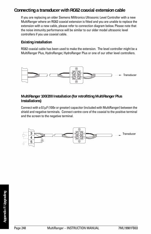
Page 248 MultiRanger � INSTRUCTION MANUAL 7ML19981FB03
mm
mm
m
App
endi
x F:
Upg
radi
ng
Connecting a transducer with RG62 coaxial extension cableIf you are replacing an older Siemens Milltronics Ultrasonic Level Controller with a new MultiRanger where an RG62 coaxial extension is fitted and you are unable to replace the extension with a new cable, please refer to connection diagram below. Please note that the noise immunity performance will be similar to our older model ultrasonic level controllers if you use coaxial cable.
Existing installation
RG62 coaxial cable has been used to make the extension. The level controller might be a MultiRanger Plus, HydroRanger, HydroRanger Plus or one of our other level controllers.
MultiRanger 100/200 Installation (for retrofitting MultiRanger Plus Installations)
Connect with a 0.1µF (100v or greater) capacitor (included with MultiRanger) between the shield and negative terminals. Connect centre core of the coaxial to the positive terminal and the screen to the negative terminal.
Transducer
Transducer

7ML19981FB03 MultiRanger � INSTRUCTION MANUAL Page 249
mm
mm
m
Appendix F: U
pgrading
MultiRanger Plus to MultiRanger 100/200 ParametersThe MultiRanger 100/200 uses the current Siemens Milltronics standard parameter set which is different than the parameter numbers used in the MultiRanger Plus.
The MultiRanger Plus parameters numbers are sequential (P-0 to P-99). The MultiRanger 100/200 parameters number are also sequential; however, some of the parameters are indexed.
Parameters are indexed when they apply to more than one input or output. The index value defines the input/output for that parameter. Indexed parameters contain a value for each index, even if that index is not used.
Example
In the MultiRanger Plus each relay had a dedicated parameter number for its function, ON and OFF points.
MultiRanger Plus Relay One
� P-8: Function� P-9 : ON setpoint� P-10: OFF setpoint
MultiRanger 100/200 uses P111 for all relays and indexes these parameters.
� P-111: Function � P-112: ON � P-113: OFF
The following tables show the differences between the MultiRanger Plus and the MultiRanger 100/200. They each show one relay programmed as a high alarm, and two relays programmed for pump control with alternating pump starts:
MultiRanger Plus
Relay Parameter Value1 P-8 (relay function) 1 (alarm)
1 P-9 (ON setpoint) 4 m
1 P10 (OFF setpoint) 3.5 m
2 P-11 (relay function) 9
2 P-12 (ON setpoint) 3.2 m
2 P-13 (OFF setpoint) 0.5 m
3 P-14 (relay function) 9
3 P-15 (ON setpoint) 3.4 m
3 P-16 (OFF setpoint) 0.6 m
MultiRanger 100/200
Relay Parameter Value1 P111 [1] (relay function) 1
1 P112 [1] (ON setpoint) 4 m
1 P113[1] (OFF setpoint) 3.5 m
2 P111[2] (relay function) 52
2 P112[2] (ON setpoint) 3.2 m
2 P113[2] (OFF setpoint) 0.5 m
3 P111[3] (relay function) 52
3 P112[3] (ON setpoint) 3.4 m
3 P113[3] (OFF setpoint) 0.6 m

Page 250 MultiRanger � INSTRUCTION MANUAL 7ML19981FB03
App
endi
x G
General Appendix G: Conduit Entry for Class 1, Div 2 Applications
2365
0314
00
S. N
GU
YEN
PETE
RBO
RO
UG
H
14/ A
UG
/ 02
ULT
RAS
ON
ICS
FOR
CO
NST
RU
CTI
ON
0
T. A
DAM
R. C
LYSD
ALE
1 : 1
12
NO
NE
HIN
GED
6 X
9 E
NC
LOSU
RE
WIT
HC
ON
DU
IT E
NTR
EES
& AS
SEM
BLE
FOR
CLA
SS 1
DIV
2 A
PPLI
CAT
ION
S
2365
0314
0
RPC
SNAU
G14
/02
6.33
1.68
89.46
0.94
0.87
5
1.50
2.62
3.25
4.62
5
DR
ILL
FO
R 1
/2”
CO
ND
UIT
HU
BS
DR
ILL
FO
R 3
/4”
CO
ND
UIT
HU
B
NO
TE
S:
1) U
SE
ON
LY C
ON
DU
IT H
UB
S C
ER
TIF
IED
/ A
PP
RO
VE
D A
S T
YP
E 4
X.
2) N
ON
ME
TAL
LIC
EN
CL
OS
UR
E D
OE
S N
OT
PR
OV
IDE
GR
OU
ND
ING
BE
TW
EE
N C
ON
DU
IT C
ON
NE
CTI
ON
S.
U
SE
GR
OU
ND
ING
TY
PE
BU
SH
ING
S A
ND
JU
MP
ER
WIR
ES
.
3) D
IME
NS
ION
S IN
CH
ES
WA
RN
ING
: –
SU
BS
TIT
UTI
ON
OF
CO
MP
ON
EN
TS
MAY
IMPA
IR
SU
ITIB
ILIT
Y F
OR
CL
AS
S I,
DIV
ISIO
N 2
EX
PL
OS
ION
HA
ZA
RD
Prod
uct G
roup

7ML19981FB03 MultiRanger � INSTRUCTION MANUAL Page 251
mm
mm
m
Appendix G
Prod
uct G
roup
2365
0314
00
S. N
GU
YEN
PETE
RBO
RO
UG
H
14/ A
UG
/ 02
ULT
RAS
ON
ICS
FOR
CO
NST
RU
CTI
ON
0
T. A
DAM
R. C
LYSD
ALE
1 : 1
22
NO
NE
HIN
GED
6 X
9 E
NC
LOSU
RE
WIT
HC
ON
DU
IT E
NTR
EES
& AS
SEM
BLE
FOR
CLA
SS 1
DIV
2 A
PPLI
CAT
ION
S
2365
0314
0
RPC
SNAU
G14
/02
L2/N L1
TB1
TB3
TB2
RELAY 1
RELAY 2
RELAY 3
RELAY 4
RELAY 5
RELAY 6
2
1
mA INPUT
SHIELD
SYNC
1
2
4 - 20 mAOUTPUTS
TS-3
SHIELD
1
2DISCRETEINPUTS
RS485
B
A
COM
1.75
�, 6-
32N
YLO
NST
AND
OFF
CER
TIFI
EDTY
CO
ELE
CTR
ON
ICS
MO
DU
LAR
PLU
G5-
6413
35(S
UPP
LIED
BY
CU
STO
MER
)
CER
TIFI
EDTY
CO
ELE
CTR
ON
ICS
MO
DU
LAR
JAC
K52
0425
-2(IN
STAL
LED
BY
SIEM
ENS
MIL
LTR
ON
ICS)
POW
ERSU
PPLY
BOAR
D MAI
NBO
ARD
1.12
� RIC
HC
OD
UAL
LO
CKI
NG
MIN
I NYL
ON
STAN
DO
FF(4
PLA
CES
)
1.75
� , 6
-32
BRAS
SST
AND
OFF
(3 P
LAC
ES)
DIS
PLAY
BOAR
D

Page 252 MultiRanger � INSTRUCTION MANUAL 7ML19981FB03
App
endi
x G
Notes

7ML19981FB03 MultiRanger � INSTRUCTION MANUAL Page 253
mm
mm
m
Index
IndexAaccuracy .............................................................4adding new functions ................................. 246alarm ................................................................ 52
bounded ................................................. 54cable fault .............................................. 54common parameters .......................... 52emptying rate ....................................... 53filling rate ............................................... 53level ......................................................... 52loss of echo ........................................... 55rate .......................................................... 53temperature .......................................... 54
alternate duty assist ................................... 241alternate duty backup .......... 57, 58, 59, 242alternate duty service .................................. 60application
test .......................................................... 85applications
preset ..................................................... 44testing ..................................................... 83
approvals ............................................................6auxiliary reading ............................................ 24Bbackup level override ................................... 45battery .............................................................. 13bit values ....................................................... 105blanking
troubleshooting .................................. 236with Span ............................................ 123
board ................................................................ 13Ccable ................................................................. 16
routing .......................................................9cabling guidelines ......................................... 90calibration
mA output .............................................. 47characterization chart .................................. 50communication ports
configuring ............................................ 92communications ............................................ 87communications installation ....................... 90configuration .....................................................2control
rake ......................................................... 67controlling the display .................................. 24
Ddata types ......................................................105
bit values ..............................................105default auxiliary reading ...............................25dimensions ................................................ 9, 38discrete inputs ........................................ 46, 98
indexing ..................................................34logic .........................................................46wiring ......................................................46
display .................................................................4auxiliary ..................................................24controlling ..............................................24distance ..................................................22echo confidence ...................................22failsafe time left ....................................22head (OCM) ............................................22multiple readings ..................................25pump hours ............................................22rate of change .......................................22temperature ...........................................22
display readout ...............................................32distance calculation ....................................225Dolphin Plus .....................................28, 33, 87
changing parameters ..........................33communication settings .....................89updating software ..............................246
Eecho confidence, run mode .........................22echo processing ...........................................224echo profile example ...................................202enabling new functions ..............................246enclosure ...........................................................6error codes ............................................ 32, 115error handling ...............................................110exponential flow .............................................77external totalizers ..........................................69Ffailsafe ..............................................................38
by relay ...................................................43fat ring ...............................................................64first in first out (FIFO) ........................... 60, 244fixed duty assist ..............................................59flash update ...................................................246flow calculation ............................................227flow sampler ....................................................70flume
cut throat ................................................80

Page 254 MultiRanger � INSTRUCTION MANUAL 7ML19981FB03
mm
mm
m
Inde
xH flume ................................................... 76Leopold Lagco ...................................... 79Palmer Bowlus ..................................... 75Parshall ........................................... 78, 82rectangular ............................................ 74universal trapezoidal .......................... 82
flush valve ....................................................... 65format words ................................................ 103Frequency Input ........................................... 153Gglobal index method ................................... 101group pumps ................................................... 65HH flume ........................................................... 165hand programmer ......................................... 26head measurement ....................................... 22head vs. flowrate breakpoints ................. 172Iin bounds ......................................................... 54independent failsafe ..................................... 63index method
global .................................................... 101parameter specific ............................ 102
index types .................................................... 223indexed parameters ..................................... 35indexing
parameters ............................................ 34points ...................................................... 34
input / output .................................................. 97inputs ...................................................................6installation ..........................................................8LLCD controlling ............................................... 24level alarms .................................................... 52LOE .................................................................... 55loss of echo (LOE) ......................................... 38
alarm ....................................................... 55MmA
calibrating .............................................. 47input ........................................................ 47loops ....................................................... 47output .............................................. 47, 48
map ID .............................................................. 96maximum process speed .......................... 229maximum separation .................................... 90measurement
difficulties ............................................ 234dual point ............................................... 37set up ...................................................... 36
setting up ................................................36single point ............................................36starting ....................................................36
Modbus ............................................................88register map ..........................................95responses ............................................110
modeprogram ..................................................26run ............................................................21
mountinginstructions ..............................................9location .....................................................8wall mount ...............................................9
multiple readings ............................................25Nnear blanking
troubleshooting ...................................236with span ..............................................123
noise problems .............................................231noise sources ................................................232OOCM (open channel monitoring) ................71
common parameters ...........................71cut throat ................................................80flow characterization chart ...............81flow exponent support ........................77H flume ....................................................76Leopold Lagco flume ...........................79Palmer Bowlus flume ..........................75Parshall flume .......................................78rectangular flume .................................74testing flow values ...............................84totalized volume ....................................73universal calculation ...........................81universal Parshall flume .....................82universal trapezoidal flume ...............82V notch weir ..........................................73weirs ........................................................77zero head ................................................72
operationdual point ................................................37single point ............................................36
options, adding .............................................246out of bounds ..................................................54outputs ................................................................5Pparameter
relays .......................................................41parameter access
data types .............................................105

7ML19981FB03 MultiRanger � INSTRUCTION MANUAL Page 255
mm
mm
m
Index
format words ...................................... 103overview .............................................. 100reading ................................................. 101writing .................................................. 102
parameter indexing ..............................34, 100parameters
advanced echo processing ............. 202advanced shot adjustment .............. 212advanced TVT adjustment .............. 209auto record setpoints ....................... 162backup level override ....................... 129calibration ........................................... 178communications ................................ 194data logging ........................................ 154discrete input functions ................... 153display .................................................. 191display and reading ........................... 127echo processing ................................ 199failsafe .................................................. 131flow records ........................................ 157flush systems ...................................... 144global ...................................................... 31independent mA setpoints .............. 148independent relay failsafe ............... 140installation records ........................... 164LCD totalizer ........................................ 158mA input ............................................... 151mA output ............................................ 146mA output failsafe ............................. 150mA output limits ................................. 149mA output trim .................................... 150master reset ........................................ 222measurement ..................................... 219measurement verification ............... 187open channel monitoring (OCM) ... 165profile pointer ..................................... 204profile records .................................... 159pump control modifiers .................... 141pump records ..................................... 156pump setpoint modifiers .................. 139pumped volume totalizer ................. 174quick start ............................................ 119rate ........................................................ 183record readings ................................. 156record temperatures ......................... 154relays .................................................... 132scrolling ................................................. 30SmartLinx hardware testing ........... 197SmartLinx reserved ........................... 194special .................................................... 31status ...................................................... 23
temperature compensation .............181test .........................................................215totalizer .................................................175transducer scanning .........................190view only ................................................31volume ..................................................123volume measurement .......................220
pointsindexing ..................................................34
ports, communication ...................................88power ................................................................19preprogrammed applications ......................44program mode ................................................26programming .....................................................4
alarms .....................................................52by hand ...................................................26relays .......................................................39
pumpalternate duty backup ................. 57, 58by rate .....................................................61hours .......................................................22off setpoint ..............................57, 58, 59on setpoints ............................57, 58, 59other controls ........................................59pump down ............................................56pump up ..................................................57reservoir .................................................57run-on ......................................................64service ratio ...........................................62start delay ..............................................64start method ........................................239totalizing volume ...................................63usage .......................................................66wet well ..................................................56
pump by rate .................................................244pump control ...................................................98
algorithms .................................... 56, 240options ..................................................239other ......................................................244reference ..............................................239
pump flush valve ............................................65pump hours ......................................................99pump starts ......................................................99Qquick start ........................................................36Rrake control .....................................................67randomize setpoints ......................................64range ...................................................................4reading

Page 256 MultiRanger � INSTRUCTION MANUAL 7ML19981FB03
mm
mm
m
Inde
xvolume .................................................... 49
recording profiles ........................................ 160register map ................................................... 95
discrete inputs ...................................... 98input/output ........................................... 97mA output .............................................. 98map ID .................................................... 96parameter access ............................. 100parameter format words ................. 103point data ............................................... 97product ID .............................................. 97pump control ......................................... 98pump hours ........................................... 99pump setpoint ................................ 98, 99pump starts ........................................... 99pumped volume ................................... 99relay outputs ......................................... 98UINT32 Order ........................................ 96
relay .................................................................. 17activation ............................................... 42failsafe .................................................... 43flow sampler ......................................... 70function codes .................................... 108indexing .................................................. 34modifiers ................................................ 41modify logic ........................................... 43outputs ................................................... 98parameters ............................................ 41programming ........................................ 39totalizer .................................................. 69wiring test .............................................. 42
resolution ...........................................................4response rate ................................................. 38RS-232 .............................................................. 20RS-485 .............................................................. 20run mode ......................................................... 21run-on ............................................................... 64Ssamplers .......................................................... 69SCADA ............................................................. 87scrolling parameters .................................... 30scum ring See wall cling ............................. 64security ............................................................ 31service ratio
applications ........................................... 62duty assist ........................................... 243duty backup ........................................ 244
simulation ........................................................ 83level cycle .............................................. 83OCM flow characterization ............... 84
single measurement ............................83volume characterization .....................84
single parameter access ............................113single point ......................................................36SmartLinx .........................................................89
installation ..............................................14Installation in Wall mount ..................14
software update ...........................................246sound velocity ...............................................225special parameters ........................................31specific auxiliary reading .............................25specifications ....................................................3standard applications ...................................44start delay ........................................................64starting measurement ..................................36status parameters ..........................................23synchronization ..............................................19Ttank shape .......................................................49temperature
alarm .......................................................54compensation .........................................4error ...........................................................4run mode ................................................22sensor .....................................................18
terminal board ................................................16testing
application .............................................85configuration .........................................83
text messages ...............................................107totalizer .............................................................69transducers ............................................... 6, 17
indexing ..................................................34transmit pulse ...............................................224troubleshooting
common problems .............................230communication ...................................112noise problems ...................................231
TS-3 ...................................................................18UUINT32 ............................................................105units or percent ..............................................31universal
example ..................................................50volume ....................................................50
unsigned double precision integer ..........105updating software ........................................246Vverify
mA output ...............................................48

7ML19981FB03 MultiRanger � INSTRUCTION MANUAL Page 257
mm
mm
m
Index
volume .............................................................. 49calculation ........................................... 226characterization chart ........................ 50dimensions ............................................ 38readings ................................................. 49tank shape ............................................. 49universal example ............................... 50
Wwall cling ......................................................... 64weight .................................................................6weir
Cipolletti ............................................... 167standard ................................................. 77V notch ................................................... 73
wet well ........................................................... 56wiring ............................................................... 15
communication .................................... 90problems .............................................. 233test .......................................................... 42
writing parameters ..................................... 102wrong reading .............................................. 236

*7ml19981FB03*Rev. 3.0
www.siemens-milltronics.com
Siemens Milltronics Process Instruments Inc.
1954Technology Drive, P.O. Box 4225
Peterborough, ON, Canada K9J 7B1
Tel: (705) 745-2431 Fax: (705) 741-0466
Email: [email protected]
Siemens Milltronics Process Instruments Inc. 2003
Subject to change without prior notice
Printed in Canada