multiresolution time-domain (mrtd) adaptive schemes...
TRANSCRIPT
IEEE TRANSACTIONS ON MICROWAVE THEORY AND TECHNIQUES, VOL. 50, NO. 2, FEBRUARY 2002 501
Multiresolution Time-Domain (MRTD) AdaptiveSchemes Using Arbitrary Resolutions of Wavelets
Emmanouil M. Tentzeris, Member, IEEE, Andreas Cangellaris, Fellow, IEEE, Linda P. B. Katehi, Fellow, IEEE,and James Harvey, Senior Member, IEEE
Abstract—A space- and time-adaptive two-dimensional mul-tiresolution time-domain (MRTD) algorithm based on arbitraryresolutions of Battle–Lemarie wavelets is proposed. Analyticexpressions for the finite-summation coefficients are derived anddetails concerning the modeling of hard boundaries, excitation,and field reconstruction are extensively discussed. Through theuse of a combination of absolute and relative thresholding, a dy-namically changing grid is developed with minimal computationalrequirements in comparison to the finite-difference time-domaintechnique. After the validation process, MRTD is used for the firsttime for the numerical optimization of complex RF structuressuch as evanescent-mode filters.
Index Terms—Adaptive gridding, FDTD, MRTD, time-domaintechniques, wavelets.
I. INTRODUCTION TOTIME-DOMAIN TECHNIQUES
SIGNIFICANT attention is being devoted today to the anal-ysis and design of various types of printed components for
microwave applications. Despite the wealth of available codes,many problems in electromagnetics, and specifically in circuitand antenna problems [e.g., monolithic microwave integratedcircuit (MMIC) packaging, multichip modules (MCMs)], havebeen left untreated due to the complexity of the geometries andthe inability of the existing techniques to deal with the require-ments for large size and high resolution due to the fine, butelectrically important geometrical details. For these cases, thestraightforward use of existing discretization methods (such asfinite difference time domain (FDTD) [1], [2]) suffers from se-rious limitations due to the required substantial computer re-sources and unrealistically long computation times. As a re-sult, during the past 30 years, the available techniques are al-most incapable of dealing with the needs of technology leadingto a quest for fundamentally different modeling approaches.Recently, the use of scaling and wavelet functions as a com-
Manuscript received April 5, 2001. This work was supported by the Na-tional Science Foundation under the CAREER Award 9984761, by the Stateof Georgia under the Yamacraw Research Initiative, and by the Georgia Insti-tute of Technology Packaging Research Center.
E. M. Tentzeris is with the School of Electrical and Computer Engi-neering, Georgia Institute of Technology, Atlanta, GA 30332 USA (e-mail:[email protected]).
A. Cangellaris is with the Department of Electrical and Computer Engi-neering, University of Illinois at Urbana-Champaign, Urbana, IL 61801 USA.
L. P. B. Katehi was with the Electrical Engineering and Computer ScienceDepartment, University of Michigan at Ann Arbor, Ann Arbor, MI 48109 USA.She is now with the Dean of Schools of Engineering, Purdue University, WestLafayette, IN 47907 USA.
J. Harvey is with the Army Research Office, Research Triangle Park, NC27709-2211 USA.
Publisher Item Identifier S 0018-9480(02)01161-4.
plete set of field basis functions resulted in the multiresolutiontime-domain (MRTD) [3] schemes that are generalizations toYee’s FDTD and can extend the capabilities of the conventionalFDTD by improving computational efficiency and substantiallyreducing computer resources by providing space and time adap-tive gridding. Though various basis have been used [4]–[9], theBattle–Lemarie family has demonstrated the better economy inmemory and execution time requirements, when only scalingfunctions have been used (cell size close to the Nyquist limit).The purpose of this paper is to extend the performance anal-ysis to MRTD schemes based on Battle–Lemarie scaling andwavelets, exploit the adaptive character of such a scheme, andlay the foundation for the use of other expansion basis.
II. FUNDAMENTALS OF MULTIRESOLUTION ANALYSIS
One of the most important characteristics of expansion toscaling and wavelet functions is the time-frequency localiza-tion. The standard approach in ideal low-pass (“scaling”) andbandpass (“wavelet”) filtering for separating an analog signalinto different frequency bands emphasizes the importance oftime localization. The multiresolution analysis (MRA), intro-duced by Mallat [10] and Meyer [11], provides a very pow-erful tool for the construction of wavelets and implementation ofthe wavelet decomposition/reconstruction algorithms. The sam-pling theorem can be used to formulate analog signal represen-tations in terms of superpositions of certain uniform shifts of asingle function called a scaling function. Stability of this signalrepresentation is achieved by imposing the Riesz condition onthe scaling function. Another important condition of an MRA isthe nested sequence of subspaces as a result of using scales byinteger powers of two.
An MRA [12] consists of a sequence of successive approxi-mation spaces . More precisely, the closed subspacessat-isfy
(1)
with
(density) (2)
(separation) (3)
The basic idea of the MRA is that whenever a collection ofclosed subspaces satisfies the multiresolution conditions, there
0018–9480/02$17.00 © 2002 IEEE

502 IEEE TRANSACTIONS ON MICROWAVE THEORY AND TECHNIQUES, VOL. 50, NO. 2, FEBRUARY 2002
exists an orthonormal wavelet basis of ,, such that for all in
(4)
where is the orthogonal projection onto . For every ,define to be the orthogonal complement of in . Wehave
(5)
and
(6)
It follows that for
(7)
where all these subspaces are orthogonal. Equation (7) is thefoundation of multiresolution. Supposing that scaling functionsof th-order approximation are used, the enhancement ofwavelets of orders to create an approximation withmuch better accuracy (th-order approximation). In otherwords, the scaling functions describe accurately the smoothfeatures of a function and the wavelets the finer details forwhich a more accurate approximation has to be used. In thisway, MRA operates as a “mathematical microscope.” Whereverneeded, a finite linear combination of wavelets can offer anarbitrarily small precision of the approximation.
It has to be noted that the spaces inherit the scaling prop-erty from the
(8)
The Battle–Lemarie wavelets [13], [14] based on theth ordercardinal B-splines belong to with , have verygood (exponential) decay though the support equals the whole
, and have vanishing moments: forfor bounded for . The choices of
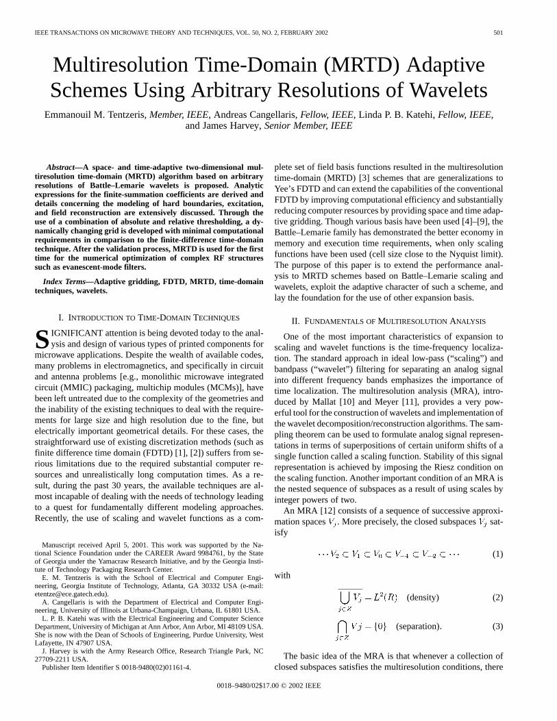
the scaling function for the remainder of this paper are the cubiccardinal spline ( ). After orthonormalization, the spectralexpressions of the cubic cardinal spline scaling and the waveletfunctions (Figs. 1–4) are
(9)
and
(10)
Fig. 1. Battle–Lemarie cubic spline scaling—spatial domain.
Fig. 2. Battle–Lemarie cubic spline zero-resolution wavelet—spatial domain.
Fig. 3. Battle–Lemarie cubic spline scaling—spectral domain (“low-pass”).
TENTZERISet al.: MRTD ADAPTIVE SCHEMES USING ARBITRARY RESOLUTIONS OF WAVELETS 503
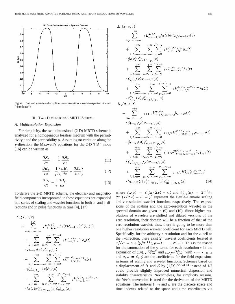
Fig. 4. Battle–Lemarie cubic spline zero-resolution wavelet—spectral domain(“bandpass”).
III. T WO-DIMENSIONAL MRTD SCHEME
A. Multiresolution Expansion
For simplicity, the two-dimensional (2-D) MRTD scheme isanalyzed for a homogeneous lossless medium with the permit-tivity and the permeability. Assuming no variation along the-direction, the Maxwell’s equations for the 2-D mode
[16] can be written as
(11)
(12)
(13)
To derive the 2-D MRTD scheme, the electric- and magnetic-field components incorporated in these equations are expandedin a series of scaling and wavelet functions in both- and -di-rections and in pulse functions in time [4], [17]
(14)
where andrepresent the Battle–Lemarie scaling
and -resolution wavelet function, respectively. The expres-sions of the scaling and the zero-resolution wavelet in thespectral domain are given in (9) and (10). Since higher res-olutions of wavelets are shifted and dilated versions of thezero resolution, their domain will be a fraction of that of thezero-resolution wavelet; thus, there is going to be more thanone higher resolution wavelet coefficient for each MRTD cell.Specifically, for the arbitrary resolution and for the cell tothe -direction, there exist wavelet coefficients located at
, . This is the reasonfor the summation of the terms for each resolution in theexpansion of (14). and withand are the coefficients for the field expansionsin terms of scaling and wavelet functions. Schemes based ona displacement of and by instead of 1/2could provide slightly improved numerical dispersion andstability characteristics. Nevertheless, for simplicity reasons,the Yee’s convention is used for the derivation of the MRTDequations. The indexes and are the discrete space andtime indexes related to the space and time coordinates via
504 IEEE TRANSACTIONS ON MICROWAVE THEORY AND TECHNIQUES, VOL. 50, NO. 2, FEBRUARY 2002
and , where are thespace discretization intervals in the- and -directions andis the time discretization interval. For an accuracy of 0.1%, theabove summations are truncated to a finite number of terms de-termined by the dispersion and stability requirements (typicallytheir maximum value is between 22–26). The time-domainexpansion function is defined as
(15)
with the rectangular pulse function
for
for
for
The magnetic-field components are shifted by half a discretiza-tion interval in the space and time domains with respect to theelectric-field components (leap-frog).
Upon inserting the field expansions, Maxwell’s equations aresampled using pulse functions as time-domain test functions andscaling/wavelet functions as space-domain test functions. Forthe sampling in the time domain, the following integrals are uti-lized:
(16)
and
(17)
where is the Kroenecker symbol
for
for
B. Battle–Lemarie Expansion Basis
Sampling in the space domain is obtained by use of theorthogonality relationships for the Battle–Lemarie scaling andwavelet functions [12]
(18)
(19)
and
(20)
The integrals containing derivatives can be approximated by thefollowing expressions:
(21)
with
(22)
and
(23)with
(24)
and
(25)with
(26)
and
(27)
with
(28)
For the remainder of this section, an expansion only in a seriesof scaling and zero-resolution wavelet functions will be consid-ered. Hints for the enhancement of additional wavelet resolu-tions will be presented where needed in the following sections.Since for the zero resolution ( ), there is only one waveletcoefficient per cell ( ), the symbols will be omitted fromthe definition of the coefficients, which will be given by
(29)with
(30)
and
(31)
TENTZERISet al.: MRTD ADAPTIVE SCHEMES USING ARBITRARY RESOLUTIONS OF WAVELETS 505
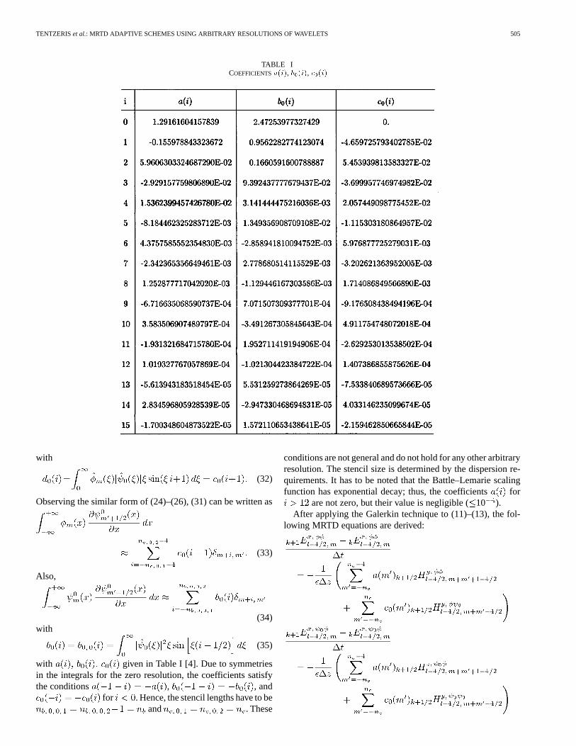
TABLE ICOEFFICIENTSa(i), b (i), c (i)
with
(32)
Observing the similar form of (24)–(26), (31) can be written as
(33)
Also,
(34)with
(35)
with given in Table I [4]. Due to symmetriesin the integrals for the zero resolution, the coefficients satisfythe conditions , , and
for . Hence, the stencil lengths have to beand . These
conditions are not general and do not hold for any other arbitraryresolution. The stencil size is determined by the dispersion re-quirements. It has to be noted that the Battle–Lemarie scalingfunction has exponential decay; thus, the coefficients for
are not zero, but their value is negligible (10 ).After applying the Galerkin technique to (11)–(13), the fol-
lowing MRTD equations are derived:
506 IEEE TRANSACTIONS ON MICROWAVE THEORY AND TECHNIQUES, VOL. 50, NO. 2, FEBRUARY 2002
(36)
The values of the stencil lengths depends on the ac-curacy and dispersion requirements. The discretization cell issimilar to the conventional FDTD cell (Fig. 5).
In [18], the stability limit for the 2-D MRTD scheme basedonly on the scaling functions’ expansion (S-MRTD) was foundto be given by
(37)
TENTZERISet al.: MRTD ADAPTIVE SCHEMES USING ARBITRARY RESOLUTIONS OF WAVELETS 507
Fig. 5. MRTD discretization cell in 3-D.
where are the cell dimensions and is thevelocity of the light in the modeled medium.
For , the above stability criterion gives
- (38)
It is known [2] that
(39)
which gives for
(40)
Equations (38)–(40) show that, for same discretization size, theupper bounds of the time steps of FDTD and S-MRTD are com-parable and related through the factor. The stability analysiscan be generalized easily to three-dimensional (3-D). The newstability criteria can be derived by (38) and (40) by substitutingthe term with .
More complicated expressions can be derived for the max-imum allowable time step for schemes containing scaling andwavelet functions. For simplicity and without loss of generality,it is assumed that the stencil size is equal for all three summa-tions ( ). The upper bound of the timestep for the 2-D MRTD scheme with zero-resolution waveletsto the one ( -direction) or two directions (- and -directions)for is given by
-
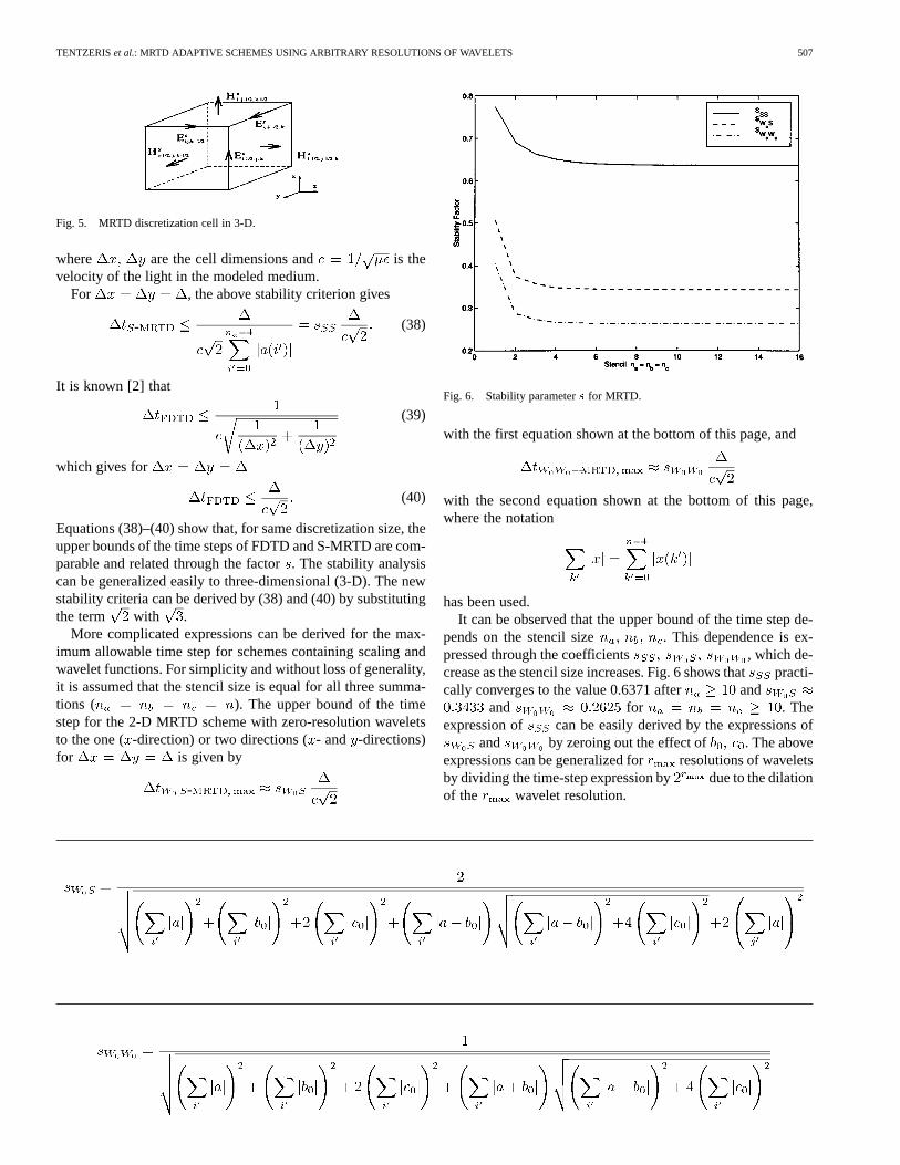
Fig. 6. Stability parameters for MRTD.
with the first equation shown at the bottom of this page, and
with the second equation shown at the bottom of this page,where the notation
has been used.It can be observed that the upper bound of the time step de-
pends on the stencil size . This dependence is ex-pressed through the coefficients , which de-crease as the stencil size increases. Fig. 6 shows thatpracti-cally converges to the value 0.6371 after and
and for . Theexpression of can be easily derived by the expressions of
and by zeroing out the effect of . The aboveexpressions can be generalized for resolutions of waveletsby dividing the time-step expression by due to the dilationof the wavelet resolution.
508 IEEE TRANSACTIONS ON MICROWAVE THEORY AND TECHNIQUES, VOL. 50, NO. 2, FEBRUARY 2002
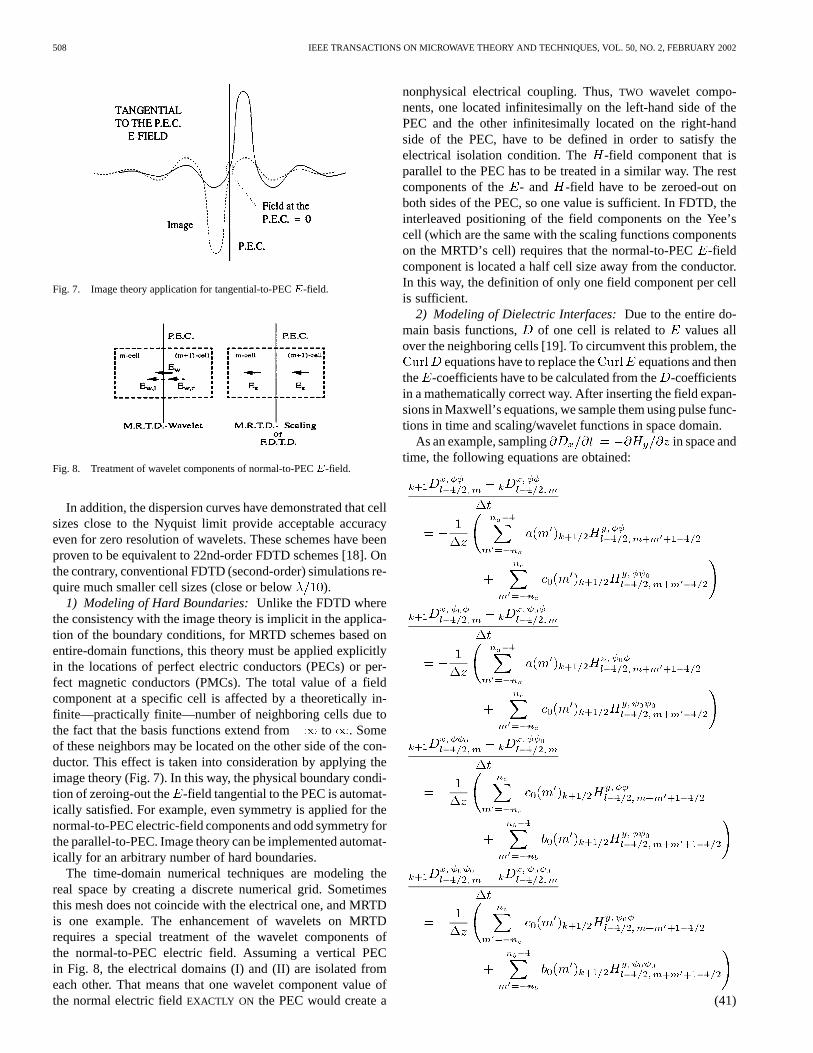
Fig. 7. Image theory application for tangential-to-PECE-field.
Fig. 8. Treatment of wavelet components of normal-to-PECE-field.
In addition, the dispersion curves have demonstrated that cellsizes close to the Nyquist limit provide acceptable accuracyeven for zero resolution of wavelets. These schemes have beenproven to be equivalent to 22nd-order FDTD schemes [18]. Onthe contrary, conventional FDTD (second-order) simulations re-quire much smaller cell sizes (close or below ).
1) Modeling of Hard Boundaries:Unlike the FDTD wherethe consistency with the image theory is implicit in the applica-tion of the boundary conditions, for MRTD schemes based onentire-domain functions, this theory must be applied explicitlyin the locations of perfect electric conductors (PECs) or per-fect magnetic conductors (PMCs). The total value of a fieldcomponent at a specific cell is affected by a theoretically in-finite—practically finite—number of neighboring cells due tothe fact that the basis functions extend from to . Someof these neighbors may be located on the other side of the con-ductor. This effect is taken into consideration by applying theimage theory (Fig. 7). In this way, the physical boundary condi-tion of zeroing-out the -field tangential to the PEC is automat-ically satisfied. For example, even symmetry is applied for thenormal-to-PEC electric-field components and odd symmetry forthe parallel-to-PEC. Image theory can be implemented automat-ically for an arbitrary number of hard boundaries.
The time-domain numerical techniques are modeling thereal space by creating a discrete numerical grid. Sometimesthis mesh does not coincide with the electrical one, and MRTDis one example. The enhancement of wavelets on MRTDrequires a special treatment of the wavelet components ofthe normal-to-PEC electric field. Assuming a vertical PECin Fig. 8, the electrical domains (I) and (II) are isolated fromeach other. That means that one wavelet component value ofthe normal electric fieldEXACTLY ON the PEC would create a
nonphysical electrical coupling. Thus,TWO wavelet compo-nents, one located infinitesimally on the left-hand side of thePEC and the other infinitesimally located on the right-handside of the PEC, have to be defined in order to satisfy theelectrical isolation condition. The -field component that isparallel to the PEC has to be treated in a similar way. The restcomponents of the - and -field have to be zeroed-out onboth sides of the PEC, so one value is sufficient. In FDTD, theinterleaved positioning of the field components on the Yee’scell (which are the same with the scaling functions componentson the MRTD’s cell) requires that the normal-to-PEC-fieldcomponent is located a half cell size away from the conductor.In this way, the definition of only one field component per cellis sufficient.
2) Modeling of Dielectric Interfaces:Due to the entire do-main basis functions, of one cell is related to values allover the neighboring cells [19]. To circumvent this problem, the
equations have to replace the equations and thenthe -coefficients have to be calculated from the-coefficientsin a mathematically correct way. After inserting the field expan-sions in Maxwell’s equations, we sample them using pulse func-tions in time and scaling/wavelet functions in space domain.
As an example, sampling in space andtime, the following equations are obtained:
(41)
TENTZERISet al.: MRTD ADAPTIVE SCHEMES USING ARBITRARY RESOLUTIONS OF WAVELETS 509
where and with (scaling),(wavelets of zero resolution) are the coefficients for the elec-tric- and magnetic-field expansions.
Starting from the constitutive relationship for thetotal electric field at one mesh point and sampling the scalingand wavelet components, we reach the following equations for
: (42)
where
(43)
and (scaling), (wavelets of zero reso-lution). Applying these equations for all neighboring cells thathave nonnegligible values for at least one coef-ficient, the following compact form is derived:
(44)
For geometries with dielectrics varying from air ( ) to Si( ), it was observed that the above summations canbe truncated for . Also, the integrals can be ap-proximated by finite summations of six cells on each side of thecentral cell ( cell). Due to the orthogonality relationship be-tween the scaling and wavelet functions, for uniform dielectrics(constant throughout the integration domain), these integralsare simplified to andfor or , transforming to a diagonal matrix.For structures containing dielectric discontinuities, some or allof these integrals have a nonzero value. In this case, the wholegeometry has to be preprocessed before the initialization of thetime loop, and the coefficients have to be as-signed to any cell and included in the matrix . For eachcell, the amplitude of these coefficients is compared to the am-plitude of the self-term . If all coefficients are belowa threshold (usually 0.1%), they are set to zero and this cell isexempted from the following inversion, otherwise it is includedin a new submatrix. For most practical cases, this submatrix hassignificantly smaller dimensions than (usually 10%) andcontains only cells close to dielectric discontinuities. The in-verse of this matrix is used for the calculation of thefromthe values for each time step. The inversion takes place onlyonce (in the preprocessing stage before the initiation of the sim-ulations), thus it adds only negligible computational overhead tothe algorithm. Even for structures with arbitrary dielectric con-figurations, the number of cells with dense submatrices (densitylarger than 50%) is going to be much smaller than the total gridsize and the matrix multiplication step for thecalculation willnot significantly affect the execution time.
3) Modeling of Excitation:Without loss of generality, themodeling of the excitation for the 2-D algorithm is presented.The two-and-one–half-dimensional (2.5-D) and 3-D algorithmis a direct extension of the 2-D algorithm.
510 IEEE TRANSACTIONS ON MICROWAVE THEORY AND TECHNIQUES, VOL. 50, NO. 2, FEBRUARY 2002
TABLE IIEXCITATION SCALING DECOMPOSITIONCOEFFICIENTS
In order to apply a point (pulse) excitation for, the pulse has to be decomposed in terms of
scaling and wavelet functions
(45)
with
(46)
Practically, the summations of (45) can be truncated to a finitenumber of terms. Usually 6–8 terms on each side of the exci-tation point per direction can offer an accuracy of representa-tion close to 0.1%. In case the neighboring scaling or waveletfunctions are located outside the computational domain (e.g.,
or for a domain tothe -direction), image theory has to be applied for their trans-lation inside the computational grid.
If there is no discontinuity (hard boundary or dielectric inter-face) in the summation interval of (45), the double integrals of(46) can be split in two single integrals
with given in Tables II and III.Due to the symmetries of the Battle–Lemarie scaling and
wavelet functions, the decomposition coefficients have to sat-isfy the following conditions:
If a hard boundary, such as a PEC, is located in the integrationdomain of the evaluation of the coefficients, the image theoryshould be applied appropriately instead of the above symmetryequations.
For each time step, the excitation scaling and wavelet com-ponents have to be superimposed to the respective field valuesobtained by the MRTD algorithm in order to provide a trans-parent source similar to FDTD as follows:
For the 2.5-D MRTD algorithm, which requires impulse exci-tation in time-domain, the above superposition takes place onlyfor the first time step . Nevertheless, for the 2-D MRTD,it has to be repeated throughout the number of time steps thatthe excitation is on. The appropriate number of the time stepswill depend on the time dependence of the excitation (usuallyGaussian, Gabor, or sinusoidal time dependence).
Arbitrary excitation spatial distributions for an area
can be modeled in a similar way. The spatial distribution has to

TENTZERISet al.: MRTD ADAPTIVE SCHEMES USING ARBITRARY RESOLUTIONS OF WAVELETS 511
TABLE IIIEXCITATION WAVELET DECOMPOSITIONCOEFFICIENTS
be sampled with scaling and wavelet functions, giving the newdecomposition coefficients
for and .For most simulations, the choice of
offers an accuracy close to 0.1%.Lossy materials can be modeled with MRTD following a pro-
cedure similar to the simulation of dielectric interfaces. The ad-ditional loss current term is given by the matrix relationship
(47)
where is the matrix consisting of the sampled conductivityprofile for each FDTD cell.
The PML numerical absorber can be easily extended for arbi-trary wavelet resolutions in a straightforward way [20]. Due tothe entire-domain nature of the Battle–Lemarie expansion basis,a matrix equation has to be solved for the perfectly matchedlayer (PML) area. For structures with inherent dielectric inho-mogeneities, the use of the effective dielectric constantpro-vides satisfactory numerical reflection performance.
4) Total Field Reconstruction:Due to the natureof the Battle–Lemarie expansion functions, the totalfield is a summation of the contributions from thenonlocalized scaling and wavelet functions. For ex-ample, the total electric field with
512 IEEE TRANSACTIONS ON MICROWAVE THEORY AND TECHNIQUES, VOL. 50, NO. 2, FEBRUARY 2002
,and is calculated in thesame way with [4] and [21] by
(48)
where andrepresent the Battle–Lemarie scaling
and -resolution wavelet function, respectively, andis the maximum wavelet resolution used in this area of thecomputational domain. It has been observed that the values
and offeraccuracy close to 0.5% for most simulations incorporating thefirst two wavelet resolutions. For the cases of narrow stripswith very sharp field discontinuities, the summation limits mustincrease up to 15–20 terms per direction.
The fact that the MRTD is based on entire-domain basis func-tions with varying values along each cell offers the unique op-portunity of a multipoint field representation per cell. The neigh-boring scaling and wavelet coefficients can be combined in anappropriate way to calculate the total field value for more thanone interior cell points. In this way, MRTD creates a mesh withmuch larger density than that offered by the nominal numberof the cells without increasing the memory requirements. Thisadditional density is very useful in the calculation of the char-acteristic impedance of planar lines, where even a small fieldvariation can cause a perturbation of the impedance value by5–10 . On the contrary, FDTD is based on pulse basis functionsthat have a constant value for each cell, offering a single-pointfield representation.
5) Generalization for Arbitrary Number of Wavelet Res-olutions: For simplicity, wavelets up to resolutionare used only to the -direction. The extension to two andthree dimensions is straightforward. Since the support of an
-resolution wavelet is one-half of the support of an-resolution wavelet, it is obvious that for each cell, there
will exist one zero-resolution wavelet, two one-resolutionwavelets, , and -resolution wavelets. As itwas noted earlier, schemes based on a displacement ofand by instead of 1/2 could provide slightly
improved numerical dispersion and stability characteristics.Their derivation is similar to the one presented in this section.After sampling Maxwell’s equations with scaling and waveletfunctions, expressions similar to (36) are derived. As anexample, sampling in space andtime, the following equations are obtained:
(49)
and
(50)
where and with (scaling),(wavelets of resolution at the -position of the cell) are thecoefficients for the electric- and magnetic-field expansions.The indexes and are the discrete space and timeindexes, which are related to the space and time coordinatesvia and , where arethe space discretization intervals in the- and -directionsand is the time discretization interval. The coefficients
are givenby (22)–(28). For an accuracy of 0.1%, the parameters
need to take values in the range of 6–12.The summation limits get decreasing values as thedifference gets larger due to the different scales of thewavelet domains reaching the minimum value of one even for
.To model a dielectric discontinuity, the starting point is the
constitutive relationship that derives the followingequations for :
(51)

TENTZERISet al.: MRTD ADAPTIVE SCHEMES USING ARBITRARY RESOLUTIONS OF WAVELETS 513
and
(52)
where the coefficients are defined by (46). For each timestep, is calculated by through the discretized Maxwell’sequations and is derived by the solution of .
In order to implement a pulse excitation atand , the space pulse is expressed in terms of
scaling and wavelet functions
(53)
where the coefficients can be calculated similarlyas shown in Section III-B.3.
The total electric field with, , and
is calculated summing up theeffect of all contributing scaling and wavelet coefficients. Thus,in a way parallel to Section III-B.4
(54)
where andrepresent the Battle–Lemarie
scaling and -resolution wavelet function, respectively.6) Time-Adaptive Gridding:The MRA is based on the fact
that the wavelets increase the local resolution of the expan-sion. Each added wavelet resolution virtually is equivalent tothe use of a denser grid with one-half cell size. In addition,wavelets have significant values close to discontinuities or near
Fig. 9. Time- and space-adaptive grid.
regions of fast field variation since they contain only high-fre-quency spatial components. There are many different ways totake advantage of these wavelet characteristics in order to createa space and time adaptive gridding algorithm. In digital signalprocessing, thresholding of the wavelet coefficients over a spe-cific time and space window (5–10 points) contribute signifi-cant memory economy (a factor between 4–8 in comparison toscaling-only expansions), but increase the implementation com-plexity and execution time. Sometimes the added computationaloverhead is greater than the previous execution time.
The simplest way to create a dynamically changing grid is tothreshold the wavelet components to a fraction (usually0.1%)of the scaling function at the same cell (space adaptiveness)and/or to an absolute threshold (usually 0.0001 or a numbersmaller than 1/10 000 of the peak of the excitation time-domainfunction) [5], [17]. This comparison is repeated for each timestep (time adaptiveness). All components below this thresholdare eliminated from the subsequent calculations. This is the sim-plest thresholding algorithm. It does not add any significantoverhead in execution time (usually10%), but it offers onlya moderate (pessimistic) economy in memory (a factor close totwo). Also, this algorithm allows for the dynamic memory allo-cation in its programming implementation by using the appro-priate programming languages (e.g., C).
The principles of the dynamically changing time- and space-adaptive grid are demonstrated in Fig. 9. A pulse is propagatingfrom the left-hand side to the right-hand side in a partially filledparallel-plate waveguide. For , the wavelets are localizedat the excitation area. They follow the propagating pulse (be-fore the incidence to the dielectric interface), creating a movingdense subgrid. After the pulse has been split in reflected andtransmitted pulses, the wavelets increase the grid resolution onlyaround these pulses. Elsewhere the wavelet components havenegligible values and are ignored.
IV. A PPLICATIONSOF MRTD
As it was stressed above, the most important feature of MRTDis the capability of adaptive gridding, which allows for the mod-eling of very fine geometrical details using cells close to Nyquistlimit everywhere else. Since there are more than one points perMRTD cell, it is possible calculating multiple wavelet resolu-tions to make use of cell sizes larger than the Nyquist limit,though the effective cell size (real cell size/subpoints per cell)
514 IEEE TRANSACTIONS ON MICROWAVE THEORY AND TECHNIQUES, VOL. 50, NO. 2, FEBRUARY 2002
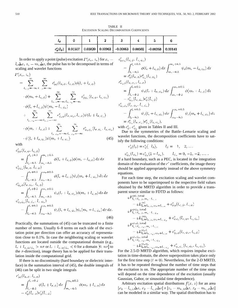
Fig. 10. Parallel-plate five-stage filter.
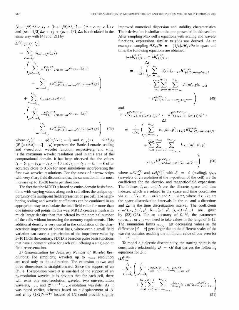
Fig. 11. Nonzero wavelets’ number.
is always smaller than this limit. For simplicity, one resolutionof wavelets was used, though more wavelet resolutions can beadded in a straightforward way.
Initially, the adaptive MRTD gridding with arbitrary resolu-tions of wavelets was applied to the simulation of a five-stageparallel-plate filter of Fig. 10 [17]. A Gabor function 0–4 GHzpropagated from the left-hand side to the right-hand side. Theinput and output stages had and the intermediatestages have (stages with mm and
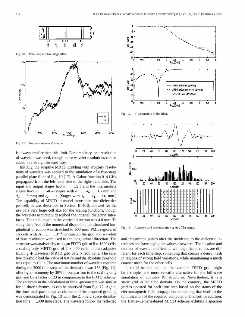
mm) and . (Stages with . mm.)The capability of MRTD to model more than one dielectricsper cell, as was described in Section III-B-2, allowed for theuse of a very large cell size for the scaling functions, thoughthe wavelets accurately described the intracell dielectric inter-faces. The total length to the vertical direction was 4.8 mm. Tostudy the effect of the numerical dispersion, the simulated lon-gitudinal direction was stretched to 600 mm. PML regions of16 cells with terminated the grid and waveletsof zero resolution were used to the longitudinal direction. Thestructure was analyzed by using an FDTD grid of 81600 cells,a scaling-only MRTD grid of 2 400 cells, and an adaptive(scaling wavelets) MRTD grid of 2 200 cells. The rela-tive threshold had the value of 0.01% and the absolute thresholdwas equal to 10 . The maximum number of wavelets requiredduring the 3000 time steps of the simulation was 153 (Fig. 11),offering an economy by 30% in comparison to the scaling onlygrid and by a factor of 23 in comparison to the FDTD scheme.The accuracy in the calculation of the-parameters was similarfor all three schemes, as can be observed from Fig. 12. Again,the time- and space-adaptive character of the proposed griddingwas demonstrated in Fig. 13 with the -field space distribu-tion for time steps. The wavelets follow the reflected
Fig. 12. S-parameters of the filter.
Fig. 13. Adaptive grid demonstration (t = 1000 steps).
and transmitted pulses after the incidence to the dielectric in-terfaces and have negligible values elsewhere. The location andnumber of wavelet coefficients with significant values are dif-ferent for each time step; something that creates a dense meshin regions of strong field variations, while maintaining a muchcoarser mesh for the other cells.
It could be claimed that the variable FDTD grid mightbe a simpler and more versatile alternative for the full-wavesimulation of complex RF structures. Nevertheless, it is astatic grid in the time domain. On the contrary, the MRTDgrid is updated for each time step based on the status of theelectromagnetic-field propagation, something that leads to theminimization of the required computational effort. In addition,the Battle–Lemarie-based MRTD scheme exhibits dispersion
TENTZERISet al.: MRTD ADAPTIVE SCHEMES USING ARBITRARY RESOLUTIONS OF WAVELETS 515
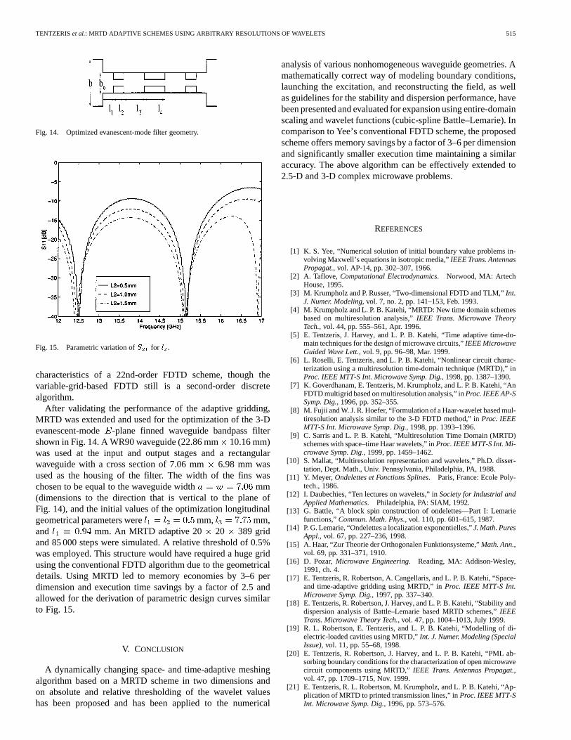
Fig. 14. Optimized evanescent-mode filter geometry.
Fig. 15. Parametric variation ofS for l .
characteristics of a 22nd-order FDTD scheme, though thevariable-grid-based FDTD still is a second-order discretealgorithm.
After validating the performance of the adaptive gridding,MRTD was extended and used for the optimization of the 3-Devanescent-mode -plane finned waveguide bandpass filtershown in Fig. 14. A WR90 waveguide (22.86 mm10.16 mm)was used at the input and output stages and a rectangularwaveguide with a cross section of 7.06 mm6.98 mm wasused as the housing of the filter. The width of the fins waschosen to be equal to the waveguide width mm(dimensions to the direction that is vertical to the plane ofFig. 14), and the initial values of the optimization longitudinalgeometrical parameters were mm, mm,and mm. An MRTD adaptive 20 20 389 gridand 85 000 steps were simulated. A relative threshold of 0.5%was employed. This structure would have required a huge gridusing the conventional FDTD algorithm due to the geometricaldetails. Using MRTD led to memory economies by 3–6 perdimension and execution time savings by a factor of 2.5 andallowed for the derivation of parametric design curves similarto Fig. 15.
V. CONCLUSION
A dynamically changing space- and time-adaptive meshingalgorithm based on a MRTD scheme in two dimensions andon absolute and relative thresholding of the wavelet valueshas been proposed and has been applied to the numerical
analysis of various nonhomogeneous waveguide geometries. Amathematically correct way of modeling boundary conditions,launching the excitation, and reconstructing the field, as wellas guidelines for the stability and dispersion performance, havebeen presented and evaluated for expansion using entire-domainscaling and wavelet functions (cubic-spline Battle–Lemarie). Incomparison to Yee’s conventional FDTD scheme, the proposedscheme offers memory savings by a factor of 3–6 per dimensionand significantly smaller execution time maintaining a similaraccuracy. The above algorithm can be effectively extended to2.5-D and 3-D complex microwave problems.
REFERENCES
[1] K. S. Yee, “Numerical solution of initial boundary value problems in-volving Maxwell’s equations in isotropic media,”IEEE Trans. AntennasPropagat., vol. AP-14, pp. 302–307, 1966.
[2] A. Taflove, Computational Electrodynamics. Norwood, MA: ArtechHouse, 1995.
[3] M. Krumpholz and P. Russer, “Two-dimensional FDTD and TLM,”Int.J. Numer. Modeling, vol. 7, no. 2, pp. 141–153, Feb. 1993.
[4] M. Krumpholz and L. P. B. Katehi, “MRTD: New time domain schemesbased on multiresolution analysis,”IEEE Trans. Microwave TheoryTech., vol. 44, pp. 555–561, Apr. 1996.
[5] E. Tentzeris, J. Harvey, and L. P. B. Katehi, “Time adaptive time-do-main techniques for the design of microwave circuits,”IEEE MicrowaveGuided Wave Lett., vol. 9, pp. 96–98, Mar. 1999.
[6] L. Roselli, E. Tentzeris, and L. P. B. Katehi, “Nonlinear circuit charac-terization using a multiresolution time-domain technique (MRTD),” inProc. IEEE MTT-S Int. Microwave Symp. Dig., 1998, pp. 1387–1390.
[7] K. Goverdhanam, E. Tentzeris, M. Krumpholz, and L. P. B. Katehi, “AnFDTD multigrid based on multiresolution analysis,” inProc. IEEE AP-SSymp. Dig., 1996, pp. 352–355.
[8] M. Fujii and W. J. R. Hoefer, “Formulation of a Haar-wavelet based mul-tiresolution analysis similar to the 3-D FDTD method,” inProc. IEEEMTT-S Int. Microwave Symp. Dig., 1998, pp. 1393–1396.
[9] C. Sarris and L. P. B. Katehi, “Multiresolution Time Domain (MRTD)schemes with space–time Haar wavelets,” inProc. IEEE MTT-S Int. Mi-crowave Symp. Dig., 1999, pp. 1459–1462.
[10] S. Mallat, “Multiresolution representation and wavelets,” Ph.D. disser-tation, Dept. Math., Univ. Pennsylvania, Philadelphia, PA, 1988.
[11] Y. Meyer,Ondelettes et Fonctions Splines. Paris, France: Ecole Poly-tech., 1986.
[12] I. Daubechies, “Ten lectures on wavelets,” inSociety for Industrial andApplied Mathematics. Philadelphia, PA: SIAM, 1992.
[13] G. Battle, “A block spin construction of ondelettes—Part I: Lemariefunctions,”Commun. Math. Phys., vol. 110, pp. 601–615, 1987.
[14] P. G. Lemarie, “Ondelettes a localization exponentielles,”J. Math. PuresAppl., vol. 67, pp. 227–236, 1998.
[15] A. Haar, “Zur Theorie der Orthogonalen Funktionsysteme,”Math. Ann.,vol. 69, pp. 331–371, 1910.
[16] D. Pozar,Microwave Engineering. Reading, MA: Addison-Wesley,1991, ch. 4.
[17] E. Tentzeris, R. Robertson, A. Cangellaris, and L. P. B. Katehi, “Space-and time-adaptive gridding using MRTD,” inProc. IEEE MTT-S Int.Microwave Symp. Dig., 1997, pp. 337–340.
[18] E. Tentzeris, R. Robertson, J. Harvey, and L. P. B. Katehi, “Stability anddispersion analysis of Battle–Lemarie based MRTD schemes,”IEEETrans. Microwave Theory Tech., vol. 47, pp. 1004–1013, July 1999.
[19] R. L. Robertson, E. Tentzeris, and L. P. B. Katehi, “Modelling of di-electric-loaded cavities using MRTD,”Int. J. Numer. Modeling (SpecialIssue), vol. 11, pp. 55–68, 1998.
[20] E. Tentzeris, R. Robertson, J. Harvey, and L. P. B. Katehi, “PML ab-sorbing boundary conditions for the characterization of open microwavecircuit components using MRTD,”IEEE Trans. Antennas Propagat.,vol. 47, pp. 1709–1715, Nov. 1999.
[21] E. Tentzeris, R. L. Robertson, M. Krumpholz, and L. P. B. Katehi, “Ap-plication of MRTD to printed transmission lines,” inProc. IEEE MTT-SInt. Microwave Symp. Dig., 1996, pp. 573–576.
516 IEEE TRANSACTIONS ON MICROWAVE THEORY AND TECHNIQUES, VOL. 50, NO. 2, FEBRUARY 2002
Emmanouil M. Tentzeris (M’90) received theDiploma degree in electrical engineering and com-puter science (suma cum laude) from the NationalTechnical University, Athens, Greece, in 1992, andthe M.S. and Ph.D. degrees in electrical engineeringand computer science from The University ofMichigan at Ann Arbor, in 1993 and 1998.
In 1998, he joined the School of Electricaland Computer Engineering, Georgia Institute ofTechnology, Atlanta, as an Assistant Professor, andis currently the leader of the Novel Integration Tech-
niques Subthrust of the Broadband Hardware Access Thrust of the YamacrawInitiative of the State of Georgia and the Packaging Research Center ThrustLeader for RF/Wireless Packaging. He has established academic programs inadaptive numerical electromagnetics, RF and wireless applications, and RFmicroelectromechanical (MEMS) modeling. He has authored or co–authoredover 70 publications, three book chapters, and numerous invited papers
Dr. Tentzeris was the 1999 Technical Program co-chair of the 54th ARFTGConference and is currently a member of the Technical Program Committeesof the IEEE Microwave Theory and Techniques (IEEE MTT-S) InternationalMicrowave Symposium (IMS) and the IEEE Antennas and Propagation Society(IEEE AP-S) Symposium. He is the vice-chair of the IEEE CPMT TC16 (RFSubcommittee). He was the recipient of the 2000 National Science FoundationCAREER Award, the 1997 International Microelectronics and Packaging So-ciety (IMAPS) Best Paper Award, and the 2001 Applied Computational Elec-tromagnetics (ACES) Best Student Paper Award.
Andreas Cangellaris (M’86–SM’97–F’00) received the Diploma degreein electrical engineering from the University of Thesalloniki, Thesalloniki,Greece, in 1981, and the M.S. and Ph.D. degrees in electrical engineering fromthe University of California at Berkeley, in 1983 and 1985, respectively.
He is currently a Professor of electrical and computer engineering at the Uni-versity of Illinois at Urbana-Champaign. Prior to joining the University of Illi-nois at Urbana-Champaign in 1997, he was with the faculty of the Departmentof Electrical and Computer Engineering, University of Arizona, from 1987 to1997. After finishing his doctoral studies, and from 1985 to 1987, he was a Se-nior Research Engineer in the Department of Electronics Engineering, GeneralMotors Research Laboratories, Warren, MI. His research interests and contribu-tions are in two major areas. The first is the area of applied computational elec-tromagnetics. The second is the area of modeling and simulation for high-speedinterconnection and package electrical analysis. He has authored and co-au-thored over 100 scientific journal and conference papers in these areas.
Prof. Cangellaris is co-founder of the IEEE Topical Meeting on ElectricalPerformance of Electronic Packaging, which is sponsored jointly by the IEEEMicrowave Theory and Techniques Society (IEEE MTT-S) and the IEEE Com-ponents, Packaging and Manufacturing Technology Society. He served as themeeting co-chair for the first three years. Since then, he serves as a member ofits Technical Program Committee. Today, this meeting is considered the premierconference on package electrical analysis and design. He is also an active partic-ipant in the Electronic Components and Technology Conference (ECTC), as amember of the Technical Program Subcommittee on Modeling and Simulation.In addition, he serves as member of the Technical Program Committee for theIEEE MTT-S International Microwave Symposium. In 1998, he was the generalchairman for the 8th Biennial Conference on Electromagnetic Field Computa-tion, Tucson, AZ, which is sponsored by the IEEE Magnetics Society.
Linda P. B. Katehi (S’81–M’84–SM’89–F’95) re-ceived the B.S.E.E. degree from the National Tech-nical University of Athens, Athens, Greece, in 1977,and the M.S.E.E. and Ph.D. degrees from the Univer-sity of California at Los Angeles, in 1981 and 1984,respectively.
In September 1984, she joined the faculty ofthe Electrical Engineering and Computer ScienceDepartment, The University of Michigan at AnnArbor, as an Assistant Professor, and then becamean Associate Professor in 1989 and Professor in
1994. She has served in many administrative positions, including Director ofGraduate Programs, College of Engineering (1995–1996), Elected Memberof the College Executive Committee (1996–1998), Associate Dean ForGraduate Education (1998–1999), and Associate Dean for Academic Affairs(1999–2001). Since January 2002, she has been the Dean of the Schools ofEngineering, Purdue University, West Lafayette, IN. She has authored or co-au-thored 410 papers published in refereed journals and symposia proceedingsand holds four U.S. patents. She has also generated 20 Ph.D. students.
Dr. Katehi is a member of the IEEE Antennas and Propagation Society(IEEE AP-S), the IEEE Microwave Theory and Techniques Society (IEEEMTT-S), Sigma Xi, Hybrid Microelectronics, and URSI Commission D. Shewas a member of the IEEE AP-S AdCom (1992–1995). She was an associateeditor for the IEEE TRANSACTIONS ONMICROWAVE THEORY AND TECHNIQUES
and the IEEE TRANSACTIONS ONANTENNAS AND PROPAGATION. She was therecipient of the 1984 IEEE AP-S W. P. King (Best Paper Award for a YoungEngineer), the 1985 IEEE AP-S S. A. Schelkunoff Award (Best Paper Award),the 1987 National Science Foundation Presidential Young Investigator Award,the 1987 URSI Booker Award, the 1994 Humboldt Research Award, the 1994University of Michigan Faculty Recognition Award, the 1996 IEEE MTT-SMicrowave Prize, the 1997 International Microelectronics and PackagingSociety (IMAPS) Best Paper Award, and the 2000 IEEE Third MillenniumMedal.
James Harvey(M’91–SM’99) is currently a Research Program Manager at theArmy Research Office, Research Triangle Park, NC, where his primary respon-sibility is within the fields of electromagnetics, antennas and antenna structures,innovative microwave and millimeter-wave circuit integration, low-power/min-imum-power system design, and landmine detection. His programs include afocus on small multifrequency multifunctional antennas for U.S. Army vehi-cles, radio propagation over complex terrain affecting data communications,and new millimeter-wave circuit integration techniques such as spatial powercombining, micromachining, and advanced electromagnetic (EM) calculationaltechniques. His personal research interests are in the fields of quasi-optics andmultiresolution analysis of EM structures.