multiscale modeling of non-crystalline ceramics (glass) · approved for public release; ... please...
TRANSCRIPT

Multiscale Modeling of Non-crystalline Ceramics (Glass)
by George A. Gazonas, James W. McCauley, Iskander G. Batyrev,Richard C. Becker, Parimal Patel, Betsy M. Rice, and N. Scott Weingarten
ARL-MR-0765 February 2011
Approved for public release; distribution is unlimited.
NOTICES
Disclaimers
The findings in this report are not to be construed as an official Department of the Army position unless so designatedby other authorized documents.
Citation of manufacturer’s or trade names does not constitute an official endorsement or approval of the use thereof.
Destroy this report when it is no longer needed. Do not return it to the originator.

Army Research LaboratoryAberdeen Proving Ground, MD 21005-5066
ARL-MR-0765 February 2011
Multiscale Modeling of Non-crystalline Ceramics (Glass)
George A. Gazonas, James W. McCauley, Iskander G. Batyrev,Richard C. Becker, Parimal Patel, Betsy M. Rice, and N. Scott Weingarten
Weapons and Materials Research Directorate, ARL
Approved for public release; distribution is unlimited.

REPORT DOCUMENTATION PAGE Form Approved OMB No. 0704-0188
Public reporting burden for this collection of information is estimated to average 1 hour per response, including the time for reviewing instructions, searching existing data sources, gathering and maintaining the data needed, and completing and reviewing the collection information. Send comments regarding this burden estimate or any other aspect of this collection of information, including suggestions for reducing the burden, to Department of Defense, Washington Headquarters Services, Directorate for Information Operations and Reports (0704-0188), 1215 Jefferson Davis Highway, Suite 1204, Arlington, VA 22202-4302. Respondents should be aware that notwithstanding any other provision of law, no person shall be subject to any penalty for failing to comply with a collection of information if it does not display a currently valid OMB control number.
PLEASE DO NOT RETURN YOUR FORM TO THE ABOVE ADDRESS.
1. REPORT DATE (DD-MM-YYYY) 2. REPORT TYPE 3. DATES COVERED (From - To)
5a. CONTRACT NUMBER
5b. GRANT NUMBER
4. TITLE AND SUBTITLE
5c. PROGRAM ELEMENT NUMBER
5d. PROJECT NUMBER
5e. TASK NUMBER
6. AUTHOR(S)
5f. WORK UNIT NUMBER
7. PERFORMING ORGANIZATION NAME(S) AND ADDRESS(ES) 8. PERFORMING ORGANIZATION REPORT NUMBER
10. SPONSOR/MONITOR'S ACRONYM(S) 9. SPONSORING/MONITORING AGENCY NAME(S) AND ADDRESS(ES)
11. SPONSOR/MONITOR'S REPORT NUMBER(S)
12. DISTRIBUTION/AVAILABILITY STATEMENT
13. SUPPLEMENTARY NOTES
14. ABSTRACT
15. SUBJECT TERMS
16. SECURITY CLASSIFICATION OF: 19a. NAME OF RESPONSIBLE PERSON
a. REPORT
b. ABSTRACT
c. THIS PAGE
17. LIMITATION OF ABSTRACT
18. NUMBER OF PAGES
19b. TELEPHONE NUMBER (Include area code)
Standard Form 298 (Rev. 8/98)
Prescribed by ANSI Std. Z39.18
February 2011 Progress
ARL-MR-0765
Approved for public release; distribution is unlimited.
June 2010-October 2010
Multiscale Modeling of Non-crystalline Ceramics (Glass)
AH84George A. Gazonas, James W. McCauley, Iskander G. Batyrev, Richard C. Becker,Parimal Patel, Betsy M. Rice, N. Scott Weingarten
U.S. Army Research LaboratoryATTN: RDRL-WMM-BAberdeen Proving Ground, MD 21005-5069
primary author’s email: <[email protected]>
This six-month progress report describes an ongoing program on the multiscale modeling of noncrystalline ceramics (glass)funded from the Director’s Strategic Initiatives (DSIs) in support of the U.S. Army Research Laboratory’s (ARL) StrategicResearch Initiatives. The long-term research goal of the program is to develop a concurrent multiscale computational finiteelement code for optimizing or enhancing the performance of various glasses against shaped-charge jets; the initial work focuseson pure fused-silica (a-SiO2), and chemically varied a-SiO2 materials. As such, this objective falls squarely within thepurview of the Weapons and Materials Research Directorate, since multiscale models are constitutive models (specific to aparticular material) wherein time evolving short and intermediate range atomic structure, order, and microcrack initiation andgrowth, are fully coupled to the macroscale, a phenomenon that cannot be modeled or accounted for using classicalhomogenization methods. A more immediate research objective is to understand why certain chemically substituted a-SiO2
materials exhibit enhanced performance in the defeat of shaped-charge jets and other ballistic threats.
multiscale modeling; fused silica; amorphous quartz; molecular dynamics; quantum mechanics; shaped charge jet
UU 38
George A. Gazonas
410-306-0863Unclassified Unclassified Unclassified
ii

Contents
List of Figures v
1. Introduction 1
2. Program Objectives 4
3. Planned Approach 5
4. Glass Technology Short Course 9
5. ARL/Momentive Performance Materials, Inc. White Paper Proposal 10
5.1 Goal: . . . . . . . . . . . . . . . . . . . . . . . . . . . . . . . . . . . . . . . . . . . . . . . . . . . . . . . . . . . . . . . . . . . . . . . . . . . . . . . . . . . . . . . . 10
5.2 Background: . . . . . . . . . . . . . . . . . . . . . . . . . . . . . . . . . . . . . . . . . . . . . . . . . . . . . . . . . . . . . . . . . . . . . . . . . . . . . . . . 10
5.3 Approach: . . . . . . . . . . . . . . . . . . . . . . . . . . . . . . . . . . . . . . . . . . . . . . . . . . . . . . . . . . . . . . . . . . . . . . . . . . . . . . . . . . 11
6. Quantum Mechanics Modeling of Glass 12
7. Molecular Dynamics Modeling of Glass 14
7.1 Interatomic Potentials. . . . . . . . . . . . . . . . . . . . . . . . . . . . . . . . . . . . . . . . . . . . . . . . . . . . . . . . . . . . . . . . . . . . . . 15
7.2 Generating Equilibrated Initial Structure of Fused Silica . . . . . . . . . . . . . . . . . . . . . . . . . . . . . . . . 15
7.3 Characterizing Fused Silica . . . . . . . . . . . . . . . . . . . . . . . . . . . . . . . . . . . . . . . . . . . . . . . . . . . . . . . . . . . . . . . 16
8. Equation-of-state Modeling of Glass 18
9. Conclusions 21
iii

10. References 23
List of Symbols, Abbreviations, and Acronyms 25
Distribution List 27
iv

List of Figures
Figure 1. Enhanced performance of SCJs into glass (a) test configuration for glass targets,and (b) penetration versus time for several targets, after Moran et al. (1). . . . . . . . . . . . . . . . . . . . . 2
Figure 2. A multiscale model for non-crystalline ceramics (glass). . . . . . . . . . . . . . . . . . . . . . . . . . . . . . . . 2
Figure 3. Five-year roadmap consistent with the WMRD brittle materials program. . . . . . . . . . . . . 6
Figure 4. Crystal structures of quartz, after Frye (2).. . . . . . . . . . . . . . . . . . . . . . . . . . . . . . . . . . . . . . . . . . . . . . 7
Figure 5. The volume-temperature diagram for a glass-forming liquid, after Varshneya (3). . . . 9
Figure 6. Brittleness versus density for glasses in the SiO2 and B2O3-based glasses, afterSehgal and Ito (4).. . . . . . . . . . . . . . . . . . . . . . . . . . . . . . . . . . . . . . . . . . . . . . . . . . . . . . . . . . . . . . . . . . . . . . . . . . . . . . . 11
Figure 7. (a) 72-atom unit cell with density 2.15 g/cm3 and (b) corresponding RDF. . . . . . . . . . . 13
Figure 8. (a) 114-atom unit cell with density 2.25 g/cm3 and (b) corresponding RDF. . . . . . . . . . 13
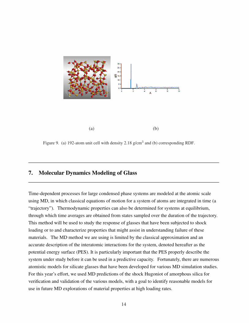
Figure 9. (a) 192-atom unit cell with density 2.18 g/cm3 and (b) corresponding RDF. . . . . . . . . . 14
Figure 10. RDFs of (a) our system using the Morse potential and (b) system in Tilocca etal. (5). . . . . . . . . . . . . . . . . . . . . . . . . . . . . . . . . . . . . . . . . . . . . . . . . . . . . . . . . . . . . . . . . . . . . . . . . . . . . . . . . . . . . . . . . . . . . 17
Figure 11. Comparison of Hugoniot curve of fused silica (a-SiO2): experiment (•), Morsepotential (×) and BKS potential (N). . . . . . . . . . . . . . . . . . . . . . . . . . . . . . . . . . . . . . . . . . . . . . . . . . . . . . . . . . . . 18
Figure 12. Stress wave distribution in fused silica. . . . . . . . . . . . . . . . . . . . . . . . . . . . . . . . . . . . . . . . . . . . . . . . . . 19
Figure 13. Energy error vs. density in fused silica. . . . . . . . . . . . . . . . . . . . . . . . . . . . . . . . . . . . . . . . . . . . . . . . . 20
Figure 14. Stress wave vs. density in fused silica compared with data from Marsh (6).. . . . . . . . . . 21
v

INTENTIONALLY LEFT BLANK.
vi

1. Introduction
Non-crystalline (amorphous) ceramics or ceramic glasses are used in a variety of vital Armypersonnel, ground, and air vehicle applications that require transparent armor − it is ubiquitous intactical vehicular windshields and side windows. Ceramic glass is inexpensive and is formableinto large, flat plate and curved shapes. For many years it has been known that the properties ofglass can be modified and enhanced through compositional modification, chemical strengthening,annealing, and process control of melt cooling. Glass ceramics, the controlled crystallization ofnano-sized single crystals in a glass matrix, offer another avenue for designed and enhancedproperty modifications for transparent and opaque material applications. In addition, certainglass formulations have been shown to exhibit enhanced performance against shaped-charge jets(SCJs) (figure 1) and other ballistic threats, but it is not understood why. This is in part due tovarious short and longer range atomic structural characteristics including atomic free volumes,cation coordinations, bridging and non-bridging oxygen (O) atoms, bonding energies, andnanoscale order characteristics (short and longer range) that are difficult or impossible to quantifyexperimentally for ceramic glass. In contrast, crystalline ceramics like silicon carbide (SiC),aluminum oxynitride (AlON ), and others have easily characterizablemicrostructures/mesostructures, which consist of assemblies of individual single-crystal grains.Ceramic glasses, on the other hand, do not have a conventional micro- or mesostructure, as it isunderstood for crystalline ceramics. However, there are microstructural scale variations inceramic glass that may include density variations from atomic free volume variations ormicroporosity, size of local atomic order, defects (inclusions, large pores, etc.), and others yet tobe determined. The interaction of a stress/shock wave from a dynamic impact involves manystructural changes not easily characterized by conventional equations of state and can involvereversible and irreversible densification and changes in bulk short range order structurescomparable to phase changes in crystalline ceramics. For example, in simple Hertzianindentation testing, a wide range of plastic or inelastic deformation mechanisms have beenobserved in a variety of glasses. Multiscale computational design methodologies (figure 2), forthis class of materials will, nevertheless, require quantitative and possibly statistically baseddescriptions of the mesoscale, although current efforts to develop such models have fallen farshort of this goal.
1

(a) (b)
Figure 1. Enhanced performance of SCJs into glass (a) test configuration for glass targets,and (b) penetration versus time for several targets, after Moran et al. (1).
���� � ���� �� ��� � ���� �� � � ������ � � �� �
�� � ��
��������������� � ����������� �� ��������� �� �����!!� �"!���!����#����� �����!���$%������ �&' ( �&')��*��+$%������ ,��- &��-�)��*��+$%������ .�������������
/012 34 5624 789:;<87=8>?@ A<B7@���������� ��� CD?98ED7 ?8 8F7G@<H?@ I9?@7 EI>=G/2 J?>@ED7 A<B7@KLMNO PQLRRSTUSV
• WXYZY[\]Z^_Y\^`a `b cdY\^Ye Y\`f^[gf^[Z`c\Zh[\hZYe c[Ye]ieYcc c\Zh[\hZ] Yaj j]b][\ [XYZY[\]Z^c\^[c• klmnopqrs ntuvu wlnl xyp uz{uwwqrs qr zuvy|zl}py }ywu~yrnu klp�yzywu�v��� �
Figure 2. A multiscale model for non-crystalline ceramics (glass).
2
Specific long-term research goals are threefold:
1. Develop molecular dynamics (MD) process models for a series of chemically substitutedamorphous silica (a-SiO2 or fused silica) materials for the prediction of glass elasticproperties assuming completely uniform glass “mesostructures.” If successful, such modelswill enable ab initio prediction of structure-property relations in glass that will be validatedwith experimentally determined elastic properties.
2. Extend the MD models to study densification of chemically substituted a-SiO2 materialsunder high pressures (∼60 GPa Materials in Extreme Dynamic Environments [MEDE])relevant to ballistic events where reversible and irreversible density changes andstructural transformations have been observed. If successful, such models will enable abinitio prediction of a-SiO2 compressibility, kinetics, and “glass” phase transformationsthat will be used to develop equations of state for a-SiO2 materials, and thus form adirect link to the continuum scale.
3. Develop a fully validated multiscale finite element computational model and codeincorporating the effects of reversible and irreversible densification, inelastic deformation,and overlain with a spatiotemporally evolving population of growing defects, which coalesceand lead to ultimate fracture and fragmentation. It is envisioned that at some time in the nottoo distant future, fully concurrent multiscale computational finite element codes will be usedby analysts on a regular basis for optimal material design!
The remainder of the report is organized as follows. General program objectives are outlined insection 2, whereas the planned approach for modeling the multiscale behavior of glass isdescribed in more detail in section 3. A one-day short course on “Glass Technology” held at theU.S. Army Research Laboratory (ARL) on October 29, 2010, is briefly described in section 4,followed by an overview of an ARL/Momentive Performance Materials purchase order forfabrication of pure and chemically substituted a-SiO2 materials that will form the basis for futureobservational and computational efforts (section 5). First principle quantum mechanical methodsare used to predict radial distribution functions (RDFs) in section 6; initial molecular dynamicsmodels using simulated annealing are then used to develop a glass shock Hugoniot for fused silicain section 7. Initial efforts at computational modeling of plate impact experiments of fused silicaappear in section 8. Section 9 summarizes the conclusions of the progress report.
3

2. Program Objectives
The long-term research goal of the program is to develop a concurrent multiscale computationalfinite element code for optimizing or enhancing the performance of various glasses against SCJs;the initial work focuses on pure fused-silica (a-SiO2), and chemically varied a-SiO2 materials.As such, this objective falls squarely within the purview of the Weapons and Materials ResearchDirectorate (WMRD), since multiscale models are constitutive models (specific to a particularmaterial) wherein time evolving microstructural changes, such as microcrack growth, are fullycoupled to the macroscale, a phenomenon that cannot be modeled or accounted for using classicalhomogenization methods. A more immediate research objective is to understand why certainchemically substituted a-SiO2 materials exhibit enhanced performance in the defeat of SCJ andother ballistic threats.
The program objectives are threefold:
1. Develop MD process models for a series of chemically substituted a-SiO2 materialsfor the prediction of glass elastic properties. This glass plays an important role in manytechnological applications and its structure has been inferred from neutron-diffraction, nuclearmagnetic resonance, and small angle x-ray scattering (SAXS) analysis to reveal a three-dimensional network consisting of tetrahedrally coordinated silicon (Si) whose structure isconstant throughout the glass and defines its short range order (SRO). Long range disorder inthe structure is manifested by a seemingly random variation in the Si-O-Si bond angle inadjacent tetrahedra. Despite the intense study of a-SiO2 glass over the last severaldecades, much controversy still exists on the best method to model (i.e., via density functionaltheory, molecular dynamics, Monte Carlo methods, or master equation techniques) thisarchetypal material for prediction of elastic properties, diffusivity, surface interactions,bond angle distribution, polyamorphism, and melt solidification. Current models that appearin the literature are often not fully validated and progress towards this goal will be made whenmodel predictions of elastic constants for a series of chemically substituted a-SiO2 glassesagree with experimentally determined constants.
2. Extend the MD models to study densification of the chemically substituted a-SiO2
materials under high pressures. Since long range order in glass is non-existent, variations inthe SRO, and intermediate range order (IRO) must be responsible for the enhancedperformance observed in ballistic tests on certain a-SiO2 glasses. If this is the case,
4

it may be possible to use MD models to predict macroscopic ballistic performance. Sinceglass is subjected to extreme pressure and temperature during a SCJ event, it will be necessaryto study the relationship between compressibility, kinetics, and phase transitions duringhigh-pressure densification of a-SiO2 glasses as manifested by changes in coordinationnumber, ring size, and free volume. Progress towards this goal will be made when MDderived equations of state (EOS) agree with those obtained experimentally via diamondanvil press and plate impact experiments.
3. Develop a fully validated multiscale finite element computational model and codethat incorporates the effects of reversible and irreversible densification, and inelasticdeformation, overlain with a spatiotemporally evolving population of defects that grow,coalesce, and lead to ultimate fragmentation. This objective will develop a computationalframework to combine the objectives from (1) and (2), and incorporate the influence offracture initiation, growth, coalescence, and fragmentation of surface and volume defectsin glass into a comprehensive concurrent multiscale finite element model and code.Microcrack initiation, growth, and coalescence (sometimes referred to as failure waves)is a multiscale phenomenon that bridges all scales in a-SiO2 glasses despite theapparent absence of a structural mesoscale for this class of materials (see figure 2).Algorithms for the development of fully two-way coupled multiscale codes are in theirinfancy, and progress on this objective will be realized with successful development andimplementation of a consistent scheme for coarse-graining localization phenomena such asfracture failure observed in glass.
3. Planned Approach
The planned approach consists of three components, which are outlined in figure 3:
1. Validate the MD models for a series of chemically substituted a-SiO2 materials for theprediction of glass elastic properties. Although there is no effort within the WMRD topredict a-SiO2 elastic properties, a hierarchical multiscale modeling effort is currentlyunderway within WMRD, which is focused on the study of polycrystalline (∼200 µm grainsize) AlON and validation of quantum and MD predictions of anisotropic elastic constantsusing diamond anvil cell and focused-ion-beam (FIB)/scanning electron microscopy (SEM)compression tests on oriented AlON single crystals (7). We plan to use MD methods(with possible MD coarse-graining) to simulate glass process modeling during melt
5

solidification by quenching a high-density, high temperature, and pressure (with possiblepolyamorphic phases) melt for a series of chemically substituted a-SiO2 materials. Next,the resulting room-temperature, chemically modified structures will be reversibly deformed topredict the elastic properties that will be validated with experimentally determined elasticproperties.
���� ���� ���� ������� �� � �������� ������� � ���������� ���!�" �# $��"" • %& '()*+,, -).+/, 0)( .+1,202*342)1)0 '5(+ 6 *7+-2*3//8 ,59,42454+. 3:;2<=-34+(23/, 0)(>13/842*3/ ?<; .+@+/)'-+14• AB CDEFGHH IEJGKH EL CMDG NFOGIPFQKKR HMSHTPTMTGJ UVWXYZIQT[KH \QKPJQTGJ SR ]^_ NSE`J KG`aTO JPHTDPSMTPE`H LDEIbbcde fghijfklmihlkng fiognpqrkqo dknpokspiq
• tuvwxuyz {|}~xzv ��zxw�yw~�� ~�zvu�yw� ��~�z�ywz� �� z��z�w}z�y�• ����� ���������� �� ������������������������� ������� ¡¢ • £¤¥¤¦§¨ ©ª©¦«¬®©¦ ¯°± ²©³¤´µ§¶ ®·¤¸®©¦¦« ³¹²³¬¬¹¬¤´ º»¼½¾¿¸©¬¤¶©¦³
• ÀÁÂÃÄÁÅÆ ÇÈÉÊÄÆÂÄÆËÌÃÍÃÎÁÅÃÊË ÏÐÆÄÃÎÅÃÊËÌÑÒÏÂÁÅÆ ÃÉÏÁÎÅ ÆÓÏÆÐÃÉÆËÅÌ • ÔÕÖ×ØÕØÙÚ ÛÜÝ ÞÙÚßàßÙÚÞÙááÕ àßâØã ä åæ×ÞâæÚØçèæÙæ×éãÞã ä ØêÖØëÞÕØÙÚã • ìíîïðññòîó ôðõóö÷ïøõòïíôùðóøóöíîøõ ïíúò ûíñ üýþÿ�� ôøóòñöøõ÷�� ����� ����� ��� �ø�ñöïøóò ùðñò � ï�òôöïøõõ�÷ð�÷óöóðóòú üýþÿ�� ôøó�õ÷ �ûð÷òú÷öõöïø���� ����� ����� ���� ���
• ���� !�"#$%& "� '#�($%")* $&"$% '�#+�#!*,%� )*&�(�, -. !�(� #�&/ "&• 01234256 789:;< =2>?36= @AB233@=5@C D EFG 56=5=• HIJKK LMNOPQIQRS TOQUV WQXUKMYZNVQ[MU \]^]_• `abcdefcghij kchcdfegihelg lmfendlohdpnhpdij onijc qideihelgo egrjioo stuv w xuvy
z{ |}~����~��� ��������� ����� ����������~� |���}��• ������������ ����������� ��������� ������ ������ ������ �� ¡¢£¤¥¦ §��������• ¨©ª«©¬ ª«®¯«°±®«²³ ´±³µ®«²³¶·©±¯·¶·³®• ¸¹º»¼»½¾ ¿¼ÀÁ»½¾ û½Ã½¿ÄºÂ¿ºÅÃÆ»»ÁÂÇÀ¿Â½¿ »ÈÆ»¼ÂÇ»½¾Ã ¹½ Æɼ» Ê˺»ÇÂËÀÌÌÍ ÃÉÎþ¾ɾ»Á ÏÐÑÒÓÔ ÇÀ¾ÌÕÕ Ö×ØÙÚ ÛÜÝØÞÙ ÚßÝÚàÛÜÚáÙâ ãá ÝäàÚ åÞæÚÜÛÞØ××ç âäèâÙÛÙäÙÚé êëìíîï ÜØÙð×â • ñòóôõö÷øóøùú÷ öûüöòùõö÷øýú÷ þÿ���� õóø��ý • ������ �������������������� ������������ ���� ����� �� ���� !�����
Figure 3. Five-year roadmap consistent with the WMRD brittle materials program.
2. Validate the MD models for densification of chemically substituted a-SiO2 materialsunder high pressures. Although there is currently no effort within WMRD to predict the EOSof chemically substituted a-SiO2 materials, MD methods have been used to predict high-pressure densification in these materials. MD simulations of pure a-SiO2 materials reveala Hugoniot elastic limit (HEL) of about 10 GPa, and an anomalous maximum incompressibility at around 3 GPa. Experiments where samples have been compressed to
6

pressures lower than 10 GPa are indistinguishable from the original material, whereas above10 GPa, materials can sustain an irreversible density increase from 10–20% higher thanthe starting material, although there is controversy as to whether the mechanism is due toirreversible coordination defects or permanent ring size modification. In contrast to thebehavior of a-SiO2, crystalline quartz (α-SiO2), undergoes very well-known highpressure polymorphic phase transitions into a Coesite phase and a Stishovite phase(figure 4), which involve changes in coordination of the Si cation from four to sixO atoms. A combination of diamond anvil press and plate impact experimentswill be conducted on a series of chemically substituted a-SiO2 materials and comparedwith MD densification simulations in glass in order to understand the influence of glassmodifiers on changes in the shock response of these materials. EOSs for a subset ofpromising chemically substituted materials will be developed and implemented into acontinuum code to determine if any of the chemically substituted materials exhibitenhanced ballistic performance.
Figure 4. Crystal structures of quartz, after Frye (2).
3. Develop a fully validated multiscale finite element computational model and code thatincorporates the effects of reversible and irreversible densification, and inelastic deformation,overlain with an spatiotemporally varying population of defects which grow, coalesce, andlead to ultimate material fragmentation. The ultimate research objective is to develop aphysics-based multiscale computational finite element code for studying densification, and
7
dynamic fracture in non-crystalline ceramics (see figure 2). Atomistic behaviorwill be linked to macroscopic elastic properties and densification behavior throughdevelopment of an EOS from first principles as outlined in (1) and (2) above. At thisstage, what remains to be accomplished, is to successfully link, in a concurrent fashion,multiscale failure phenomena in a-SiO2 materials by incorporating the important role thatpre-existing surface and volume defects have on the microcrack growth, coalescence, andfragmentation in this class of materials. Over the past five years, the first author hasalso been directly involved in development of a parallel, concurrent multiscale code forheterogeneous viscoelastic composites (8) under the auspices of an ARL/University ofNebraska cooperative agreement, which will be leveraged and used as the framework for thedevelopment of a concurrent multiscale model of a-SiO2 materials. The chief challenge forbrittle materials is to correctly account for the growth kinetics of microcracks in amultiscale computational environment. The propagation of free internal boundaries at lowerscales will be “coarse-grained,” to higher scales where global fracture failure andfragmentation is observed. As such, coarse-graining algorithms will need to be validatedthrough continuum-scale experiments on a-SiO2 materials that measure dynamic crackpropagation speeds, mixed-mode failure, and crack bifurcation phenomena using coherentgradient sensing and high speed imaging techniques; ARL possesses capabilities forconducting such dynamic fracture experiments in a-SiO2 materials through the recentestablishment of a coherent gradient sensing/imaging facility funded by the ongoingmultiscale modeling effort of AlON . Models and validation of the initiation andpropagation of discrete fractures in a-SiO2 materials should transition naturally intomodels of fragmentation and comminution for behind-armor-debris applications.Fragmentation experiments have classically been conducted using dynamically expandingring experiments for defining fragment size versus strain rate and will be used tovalidate computational models of fragmentation. The development of consistent coarse-graining algorithms for fracture in materials, which is associated with failure and loss ofmaterial stability, is largely unexplored and is the primary high-risk goal of this section.
8

4. Glass Technology Short Course
A one-day short course on the “Fundamentals of Glass Science,” was taught by Professor Arun K.Varshneya, Alfred University, at ARL on October 29, 2010. Course attendees received copies ofVarshneya’s Fundamentals of Inorganic Glasses (3). The course covered topics on (1) basiccompositions and families of commercial glasses that include vitreous silicates, soda-limesilicates, borosilicates, lead silicates, and aluminosilicates; (2) fundamentals of the glassy state;(3) phase separation and liquid-liquid immiscibility; (4) glass structures: oxide and non-oxideglasses; (5) review of some glass properties (e.g., elastic properties, hardness, viscosity, thermalexpansion, durability); and (6) annealing and strengthening.
The course was well received, and a question and answer period ensued with questions like,“What is the difference between a glass and an amorphous material?” Answer: “Amorphousmaterials make a continuous or discontinuous volume transition to a crystal or vapor on heating,whereas, glasses continuously change to a liquid on heating.” See also, p. 17 and 18 inVarshneya (3), and figure 5.
Figure 5. The volume-temperature diagram for a glass-forming liquid, afterVarshneya (3).
9

5. ARL/Momentive Performance Materials, Inc. White Paper Proposal
The following sections are quoted from the Momentive Performance Materials, Inc.∗ white paperproposal.
5.1 Goal:
The goal of the work outlined in this proposal is to produce several unique high silicaglasses and submit them to the Army Research Laboratory for ballistic performanceevaluation. Utilizing our internal capabilities and those of our partners we willpropose select glass compositions and evaluate the glasses in terms ofthermomechanical, chemical, and mechanical properties. A select subset of glasseswill then be produced in a form suitable for ballistic testing. While this brief studywill not allow us to elucidate all the complex interactions between of glasscomposition and ballistic mechanical properties, this scoping trial should give ussome guidance as to how much additional improvement might be possible inhigh-silica, low density glasses with additional research.
5.2 Background:
While there are inevitable tradeoffs between weight and ballistic performance,improvements to the base material can offer significant benefits to a previouslyoptimized package. For instance, fused silica has a better stopping power and alower density than soda-lime-silica glass resulting in a higher performance/massfigure of merit . However, fused silica suffers from a large amount of secondaryfracture created during the initial impact making the window less clear and probablyreducing it’s resistance to further impacts. While the cause of this is not understood,one might surmise that it is driven by the atomic structure of the glass (i.e. numberof non-bridging O, ring density, etc.) that can be impacted by the chemistry of theglass. These compositional and structural differences affect how the impact energytransfers within the glass and where the energy absorbing fractures take place. Forexample, Sehgal and Ito (4) found that changes in density of silica glass had a largeimpact on brittleness (see figure 6 below from Sehgal and Ito (4)). If a reduction inbrittleness translates to improved (reduced) secondary fracture and it can be
∗Richmond Heights, OH 44143
10

accomplished without substantially increasing the density of the glass (i.e. stayingnear high-silica glass compositions) then significant optimization might be possible.
Figure 6. Brittleness versus density for glasses in the SiO2 and B2O3-basedglasses, after Sehgal and Ito (4).
5.3 Approach:
We will produce high silica glasses with additions of up to 10 wt% of networkformers and modifiers using Momentive’s lab scale puck fusion process attemperatures up to 1900C. These glasses will be characterized (density, UV-Vistransmission) and evaluated mechanically to determine their hardness and“brittleness” following the methods outlined in references (4, 9), In addition,viscosity data will be collected to assist in selecting proper temperatures for largerscale melting of the glasses in phase 2. Candidate compositions from phase one thatmight exhibit improved secondary fracture will be melted in phase 2 using our 200 lbingot test melter. These ingot samples will be large enough to produce several12"x12" windows. The cut and polished windows will be furnished to ARL forassembly and ballistic testing to validate the small scale mechanical testing resultsand determine whether these relatively minor changes in composition cansignificantly affect the secondary cracking phenomenon and result in an optimizedhigh silica glass.
To date, fused silica samples have been delivered to ARL and have been ballistically tested.
11
6. Quantum Mechanics Modeling of Glass
We used a first principles quantum mechanics method, the Vienna ab initio simulation package(VASP) (10) to optimize the amorphous structure of a continuous random network, generated bya Monte Carlo bond switching model (11). A projector augmented-wave basis with an energycutoff of 600 eV was used. Brillouin-zone integrations were carried out using two special kpoints. Atomic relaxations were performed until the maximum forces on atoms became less than0.01 eV/Å; reaction barriers were calculated using the elastic-band method. Convergence testsindicate that the energies reported have an uncertainty of less than 0.05 eV.
The optimized structures have different densities (2.04–2.25 g/cm3), different numbers of atoms(72, 114, and 192), and different distributions of atoms in the rings (3–7 member rings in thestructure shown in figure 7(a) and 4–6 rings in the structures shown in figures 8(a) and 9(a)) ofrandom continuous networks. The model has an amorphous structure inside the unit cell andperiodic boundary conditions, and was found quite efficient for probing of the interaction ofhydrogen containing fractions with network of silica (12). RDFs (atomic density variations withdistance from a particular atom) calculated for these structures are presented in figures 7(b), 8(b),and 9(b). Positions of two first peaks are in reasonable agreement with experimental RDFobtained from x-ray diffraction (13). The calculation of bulk modulus, B, from a strain-energyrelationship and simple hydrostatic pressure for a cubic unit cell with 114 atoms depicted in 8(a)resulted in B = 40.6 GPa. We plan to calculate the bulk modulus and elastic constants for otheroptimized models of silica.
12

(a) (b)
Figure 7. (a) 72-atom unit cell with density 2.15 g/cm3 and (b) corresponding RDF.
(a) (b)
Figure 8. (a) 114-atom unit cell with density 2.25 g/cm3 and (b) corresponding RDF.
13
(a) (b)
Figure 9. (a) 192-atom unit cell with density 2.18 g/cm3 and (b) corresponding RDF.
7. Molecular Dynamics Modeling of Glass
Time-dependent processes for large condensed phase systems are modeled at the atomic scaleusing MD, in which classical equations of motion for a system of atoms are integrated in time (a“trajectory”). Thermodynamic properties can also be determined for systems at equilibrium,through which time averages are obtained from states sampled over the duration of the trajectory.This method will be used to study the response of glasses that have been subjected to shockloading or to and characterize properties that might assist in understanding failure of thesematerials. The MD method we are using is limited by the classical approximation and anaccurate description of the interatomic interactions for the system, denoted hereafter as thepotential energy surface (PES). It is particularly important that the PES properly describe thesystem under study before it can be used in a predictive capacity. Fortunately, there are numerousatomistic models for silicate glasses that have been developed for various MD simulation studies.For this year’s effort, we used MD predictions of the shock Hugoniot of amorphous silica forverification and validation of the various models, with a goal to identify reasonable models foruse in future MD explorations of material properties at high loading rates.
14
7.1 Interatomic Potentials
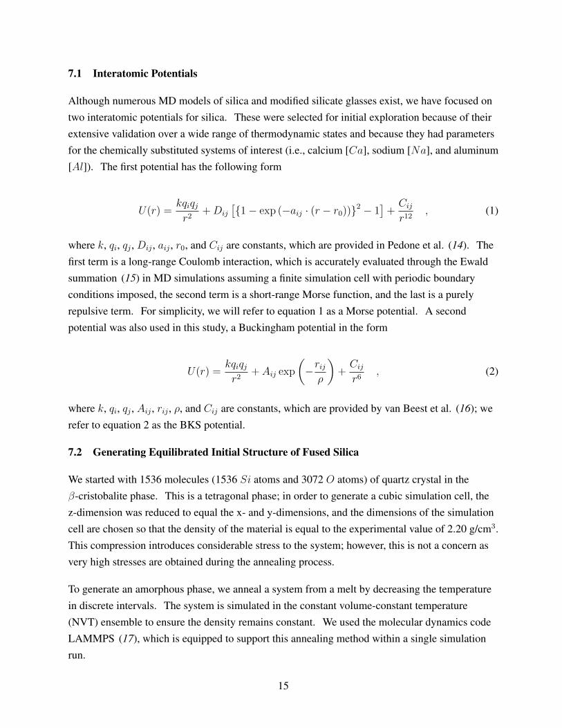
Although numerous MD models of silica and modified silicate glasses exist, we have focused ontwo interatomic potentials for silica. These were selected for initial exploration because of theirextensive validation over a wide range of thermodynamic states and because they had parametersfor the chemically substituted systems of interest (i.e., calcium [Ca], sodium [Na], and aluminum[Al]). The first potential has the following form
U(r) =kqiqjr2
+Dij
[{1− exp (−aij · (r − r0))}2 − 1]+
Cij
r12, (1)
where k, qi, qj , Dij , aij , r0, and Cij are constants, which are provided in Pedone et al. (14). Thefirst term is a long-range Coulomb interaction, which is accurately evaluated through the Ewaldsummation (15) in MD simulations assuming a finite simulation cell with periodic boundaryconditions imposed, the second term is a short-range Morse function, and the last is a purelyrepulsive term. For simplicity, we will refer to equation 1 as a Morse potential. A secondpotential was also used in this study, a Buckingham potential in the form
U(r) =kqiqjr2
+ Aij exp
(−rij
ρ
)+
Cij
r6, (2)
where k, qi, qj , Aij , rij , ρ, and Cij are constants, which are provided by van Beest et al. (16); werefer to equation 2 as the BKS potential.
7.2 Generating Equilibrated Initial Structure of Fused Silica
We started with 1536 molecules (1536 Si atoms and 3072 O atoms) of quartz crystal in theβ-cristobalite phase. This is a tetragonal phase; in order to generate a cubic simulation cell, thez-dimension was reduced to equal the x- and y-dimensions, and the dimensions of the simulationcell are chosen so that the density of the material is equal to the experimental value of 2.20 g/cm3.This compression introduces considerable stress to the system; however, this is not a concern asvery high stresses are obtained during the annealing process.
To generate an amorphous phase, we anneal a system from a melt by decreasing the temperaturein discrete intervals. The system is simulated in the constant volume-constant temperature(NVT) ensemble to ensure the density remains constant. We used the molecular dynamics codeLAMMPS (17), which is equipped to support this annealing method within a single simulationrun.
15
Using the Morse potential (equation 1), the temperature was decreased in discrete intervalsfollowing the schedule provided in Pedone et al. (14). Starting at 5000 K, the system wasequilibrated by scaling the velocity every time step for 6000 steps, then scaling was reduced toevery 40 time steps for 6000 steps, and finally velocity scaling was turned off for the final 8000steps. The temperature of the system was then decreased by 500 K, and the process was repeateduntil the temperature of the system reached 300 K. This results in a total simulation time of 470ps, which is a nominal cooling rate of 10 K/ps.
7.3 Characterizing Fused Silica
The final configuration from the annealing simulation described in the previous section was usedas the initial configuration in constant pressure-constant temperature (NPT ) simulations usingboth forms of the interatomic potential (equations 1 and 2). All simulations in this section wererun using the DL_POLY MD suite of codes (18). The timestep for the NPT simulations was 0.2fs, with barostatting and thermostatting rates of 0.5 and 1.0 ps, respectively. The simulationswere run for 60 ps, following a 10-ps equilibration with velocity scaling every 10 time steps. Theresults were analyzed to obtain structural details of the amorphous material.
Our first criterion in evaluating the interatomic potential is the ambient state density, which wecompare to the experimental value of 2.20 g/cm3. The Morse potential resulted in a density of2.26 g/cm3, slightly higher than the experimental value, while the BKS potential produced aneven higher density of 2.34 g/cm3. The density of the Morse potential is within 3% of theexperimental value, but the error in the BKS density is greater than 6% , which is higher thantypically acceptable. We also calculated partial RDFs for the three atomic pairs, Si-O, Si-Si andO-O, using both potentials. The difference in RDFs between the Morse and BKS potentials wasnegligible; hence, in figure 10 we compare the Morse potential RDFs to those from a shell modelpotential for silica (5). Except for a slight difference in the height of the first peak, figures 10(a)and 10(b) are nearly identical. This indicates that the Morse and BKS models accurately capturethe expected structure of fused silica. We note that the Tilocca et al. (5) model was notconsidered for use in this project due to numerical difficulties associated with integratingtrajectories using this model under compression.
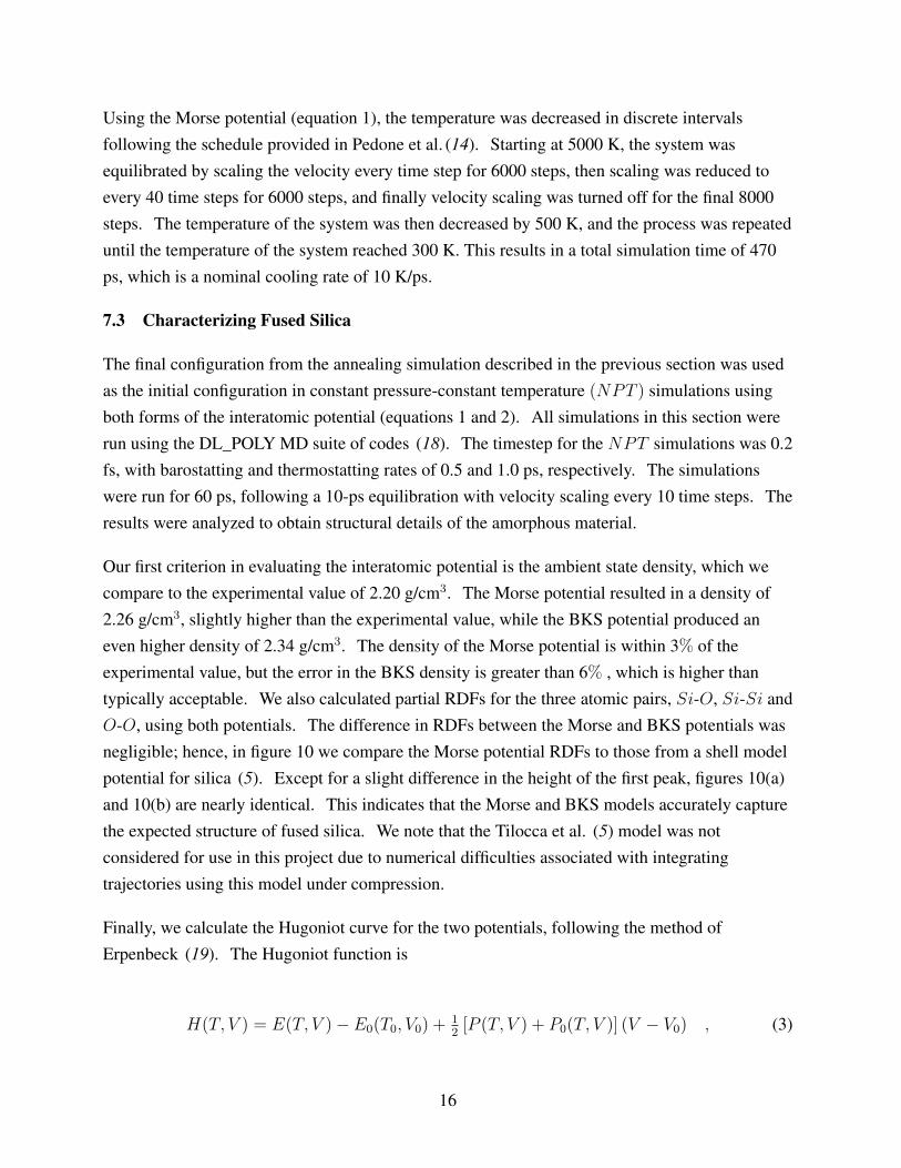
Finally, we calculate the Hugoniot curve for the two potentials, following the method ofErpenbeck (19). The Hugoniot function is
H(T, V ) = E(T, V )− E0(T0, V0) +12[P (T, V ) + P0(T, V )] (V − V0) , (3)
16

(a) (b)
Figure 10. RDFs of (a) our system using the Morse potential and (b) system inTilocca et al. (5).
where T and P represent the temperature and pressure, V and E represent the volume/unit massand internal energy/unit mass, and the subscript 0 indicates the unshocked reference state. AHugoniot curve represents a set of (P, V, T ) points for which equation 3 is equal to zero. Tocalculate a single point, a series of constant volume-constant temperature (NV T ) simulations isperformed over a range of temperatures, all at the same volume. The Hugoniot as a function oftemperature is fitted to a polynomial, and the H = 0 value is interpolated. (For our calculations,a linear fit was sufficient to extract the Hugoniot temperature). Pressure data as a function oftemperature can then be fitted to a polynomial to determine the corresponding pressure at theHugoniot temperature. Figure 11 shows the Hugoniot curves for both the Morse and BKSpotentials, represented as pressure versus volume ratio (V/V0 or relative volume), as well as theexperimental values for comparison. We see that at high values of V/V0, the Morse potential isnearly in agreement with experimental results, while at low values of V/V0 the pressure is toohigh. Conversely, the BKS potential shows better agreement at low values of V/V0, but thepressure is too low at higher values of V/V0. We performed several numerical experiments inwhich we scaled various parameters of the two PES functions in order to obtain good agreementof the shock Hugoniot at both high and low densities; however, any improvement in the Hugoniotcurve corresponded to an increased error in the density. The discrepancies between our Hugoniotcurves and the experimental values render these models inadequate for our modelingrequirements. We are continuing to evaluate other a-SiO2 atomistic models, as well as exploringthe possibility of fitting parameters using force matching techniques of Izvekov et al. (20).
17

Figure 11. Comparison of Hugoniot curve of fused silica(a-SiO2): experiment (•), Morse potential (×) andBKS potential (N).
8. Equation-of-state Modeling of Glass
Validation of the equation of state (EOS) constructed from multiscale modeling will be throughcomparison with continuum data. Bulk modulus data exist in the literature for several commonSiO2-based glasses measured in high pressure fixtures and diamond anvil cells (DACs) forpressures up to approximately 10 GPa. Similar quasi-static data can be extracted for thecompositions examined in this study if resources permit. In the neighborhood of approximately10 GPa pressure, many glasses begin permanent rearrangement on the atomic scale. While it ispossible to continue measurement of bulk modulus in a DAC beyond this point, there is noestablished way to measure density in the amorphous glasses. Consequently, validating themodel predictions at higher pressure with quasi-static data will be challenging. Experimentaltechniques development is needed to pursue validation at higher quasi-static pressures.Alternatively, EOS model validation at high pressures can also be accomplished throughcomparison with Hugoniot data from shock experiments. One must also be careful when usingthe shock data, but the approximations in the data interpretation tend to diminish as pressureincreases. Two of the features that must be dealt with are strength and non-recoverable volume
18

change. To determine the extent to which these features complicate the data, finite elementsimulations replicating symmetric impact, gas gun Hugoniot experiments were run inALE3D (21) using the Livermore Equation of State (LEOS) tables for fused silica. Thesimulations were run with and without strength to quantify the differences. The constant strengthmodel is used to introduce a limit to the elastic shear response. Data on inelastic shear strengthas a function of deformation were not found in the literature, so the constant flow strength is acrude approximation for a behavior that likely depends on density, strain, strain rate, pressure, andtemperature. Figure 12 presents the axial stress distribution at the shock front for an impactvelocity of 4 km/s. Shown is the expected three-wave structure (traveling to the right in the plot),with the first step due to the limit on the elastic shear stiffness and the second due to the volumecollapse.
0
5
10
15
20
25
0.00 0.05 0.10 0.15 0.20
Str
es
s (
GP
a)
Distance (mm)
HugoniotElastic Limit
Volume Collapse
Figure 12. Stress wave distribution in fused silica.
The wave front is not steady at this lower impact pressure in that the three-wave fronts continue toseparate over time. A steady wave is assumed when analyzing data in the context of theHugoniot equations, and that introduces uncertainty when computing the energy dissipation andstress. One is faced with the question of which wave front to use to compute the wave speedwhen analyzing the data. The experimental results under these low pressure conditions must beput in the context of how the data were reduced. At higher impact pressures, the plastic wave andthe transformation front both overtake the elastic precursor and create a strong shock. Underthese higher pressure conditions, the data analysis is not ambiguous.
19

The plot in figure 13 provides some indication of the error in the energy calculation. The errormetric plotted is the difference between the energy computed by the finite element code and theideal energy computed assuming the Hugoniot relations apply. Normalization is by the idealenergy. It can be seen that the deviation from the Hugoniot conditions is significant at lowercompressions but nearly zero at densities above 4.3 g/cm3. This coincides with development of astrong shock as described previously. It should also be noted that the energy error is significantlygreater for the calculation with strength. The energy from inelastic dissipation is not capturedproperly by the Hugoniot energy balance in the low pressure regime where the elastic precursoroutpaces the plastic wave. The error vanishes when the plastic wave overtakes the elasticprecursor and the wave becomes steady.
0.00
0.02
0.04
0.06
0.08
0.10
0.12
2.0 3.0 4.0 5.0
Re
lati
ve
En
erg
y E
rro
r
Density (g/cm3)
Strength = 5 GPa
No Strength
Figure 13. Energy error vs. density in fused silica.
The stress density plots from the simulations are shown along with data by Marsh (6) in figure14. It can be seen that the LEOS table reproduces the data reasonably well in the high pressurerange. The strength used in the simulations can make an appreciable difference at lower pressurebut because the strength was specified as constant rather than pressure dependent, the relativeinfluence decays as the pressure increases. Simulations were not run at lower pressures becausethe results are increasingly dominated by the assumed strength model and volume collapse,neither of which is thought to be accurate in these simulations. The initial density is 2.204 g/cm3,so there is a significant span of density change where the volume collapse and strength dominate.
20

These simple analyses illustrate that strength effects on gas gun results for glass can beappreciable, because the strength is a significant fraction of the total stress. The strength andwhether or not the waves are steady should be considered when using the data to calibrate an EOSor validate multiscale results.
0
10
20
30
40
50
60
70
80
90
2.0 3.0 4.0 5.0
Str
es
s (
GP
a)
Density (g/cm3)
LASL Handbook, Marsh
Strength = 5 GPa
No Strength
Figure 14. Stress wave vs. density in fused silicacompared with data from Marsh (6).
9. Conclusions
This six-month progress report on multiscale modeling of noncrystalline ceramics (glass) hasfocused on establishing the framework for development of a multiscale computationalmethodology for optimizing or enhancing the performance of fused silica materials not yetsynthesized. A more immediate research objective is to understand why certain chemicallysubstituted fused silica materials exhibit enhanced performance in the defeat of SCJs and otherballistic threats. Conclusions consistent with the milestones shown in the five-year roadmapshown in figure 3 are as follows:
1. Professor Arun K. Varshneya of Alfred University, gave a short course on “Fundamentals ofGlass Science,” at the ARL on October 29, 2010; course attendees received copies ofFundamentals of Inorganic Glasses (3), as well as a variety of practical considerationsregarding glass formation and technology.
21

2. Fused silica specimens have been delivered to ARL under the auspices of an ongoingcooperative agreement; these specimens have been ballistically tested, and will serve tovalidate future computational models of fused silica.
3. A first principles quantum mechanics method (VASP) (10) was used to optimize theamorphous structure of a continuous random network, generated by a Monte Carlo bondswitching model (11). A projector augmented-wave basis with an energy cutoff of 600 eVwas used. The optimized structures have different densities (2.04–2.25 g/cm3), differentnumbers of atoms (72, 114, and 192), and different distributions of atoms in the rings (3–7member rings in the structure shown in figure 7(a) and 4–6 rings in the structures shownin figures 8(a) and 9(a)) of random continuous networks. RDFs calculated for thesestructures are presented in figures 7(b), 8(b), and 9(b). Positions of two first peaksare in reasonable agreement with experimental RDF obtained from x-ray diffraction (13).
4. Initial fused silica glass structures were generated via LAMMPS (17) simulations bysimulated annealing the system from a melt via a Morse potential (equation 1) using theschedule provided in Pedone et al. (14). Final configurations from the simulated annealingruns were used as the initial configurations for DL_POLY (18) predictions of RDFs for fusedsilica, which compared favorably with the results of Tilocca et al. (5);
5. Hugoniot curves for fused silica were calculated using the method of Erpenbeck (19) usingboth Morse and BKS potentials. The Morse potential accurately models pressure at a relativevolume greater than 0.7, yet overpredicts pressure at a lower relative volume. The BKSpotential accurately predicts pressure at a relative volume on the order of 0.5, butunderpredicts pressure at larger relative volumes. The discrepancies between the computedHugoniot values and experimental data render these potentials inadequate for our modelingrequirements, and we are evaluating other a-SiO2 atomistic models, as well as exploringthe possibility of fitting parameters using force matching techniques of Izvekov et al. (20).
6. Symmetric gas gun impact simulations on fused silica were conducted using the ALE3D codebased on data from the LEOS tables. The classic three-wave structure was observed in thefused silica simulations, and stress versus density calculations reproduced the experimentaldata reasonably well in the high pressure range. The strength used in the simulations canmake an appreciable difference at lower pressure because the strength was specified asconstant rather than pressure dependent, and it was shown that the relative influence decaysas the pressure is increased.
22

10. References
1. Moran, B.; Glenn, L. A.; Kusubov, A. Jet Penetration in Glass. J. Phys. IV 1991, 1 (C3),147–154.
2. Frye, K. Modern Mineralogy; Prentice-Hall, Inc.: Englewood Cliffs, NJ, 1974.
3. Varshneya, A. K. Fundamentals of Inorganic Glasses; 2nd ed.; Society of GlassTechnology: Sheffield, 2006.
4. Sehgal, J.; Ito, S. Brittleness of Glass. J. Non-Cryst. Solids 1999, 253, 126–132.
5. Tilocca, A.; de Leeuw, N. H.; Cormack, A. N. Shell-model Molecular DynamicsCalculations of Modified Silicate Glasses. Phys. Rev. B 2006, 73 (10), 104209.
6. Marsh, S. P., Ed. LASL Shock Hugoniot Data; University of California Press: Berkeley,CA, 1980.
7. Gazonas, G. A.; McCauley, J. W.; Batyrev, I. G.; Casem, D.; Clayton, J. D.;Dandekar, D. P.; Kraft, R.; Love, B. M.; Rice, B. M.; Schuster, B. E.; Weingarten, N. S.Multiscale Modeling of Armor Ceramics: Focus on AlON. Proceedings of the 27th Army
Science Conference 2010, to appear.
8. Souza, F. V.; Allen, D. H. Multiscale Modeling of Impact on Heterogeneous ViscoelasticSolids Containing Evolving Microcracks. Int. J. Numer. Meth. Eng. 2010, 82 (4), 464–504.
9. Ito, S. Structural Study on Mechanical Behavior of Glass. J. Ceram. Soc. Jpn. 2004,112 (1309), 477–485.
10. Kresse, G.; Hafner, J. Norm-conserving and Ultrasoft Pseudopotentials for First-row andTransition-elements. J. Phys.: Condens. Mat. 1994, 6 (40), 8245–8257.
11. Tu, Y. H.; Tersoff, J.; Grinstein, G.; Vanderbilt, D. Properties of aContinuous-random-network Model for Amorphous Systems. Phys. Rev. Lett. 1998,81 (22), 4899–4902.
12. Batyrev, I. G.; Tuttle, B.; Fleetwood, D. M.; Schrimpf, R. D.; Tsetseris, L.;Pantelides, S. T. Reactions of Water Molecules in Silica-based Network Glasses. Phys. Rev.
Lett. 2008, 100 (10), 105503.
23
13. Konnert, J. H.; D’Antonio, P.; Karle, J. Comparison of Radial-Distribution Function forSilica Glass with Those for Various Bonding Topologies - Use of Correlation-function. J.
Non-Cryst. Solids 1982, 53 (1-2), 135–141.
14. Pedone, A.; Malavasi, G.; Menziani, M. C.; Cormack, A. N.; Segre, U. A NewSelf-consistent Empirical Interatomic Potential Model for Oxides, Silicates, and Silica-basedGlasses. J. Phys. Chem. B 2006, 110 (24), 11780–11795.
15. Ewald, P. P. Die Berechnung Optischer und Elektrostatischer Gitterpotentiale. Ann. Phys.
1921, 369, 253–287.
16. van Beest, B. W. H.; Kramer, G. J.; van Santen, R. A. Force-fields for Silicas andAluminophosphates Based on Ab Initio Calculations. Phys. Rev. Lett. 1990, 64 (16),1955–1958.
17. Plimpton, S. J. LAMMPS Users Manual: Large-scale Atomic/Molecular Massively Parallel
Simulator; Sandia Corporation: Sandia National Laboratories, 2003.
18. Todorov, I. T.; Smith, W. The DL_POLY 4 User Manual, Version 4.01.0; STFC DaresburyLaboratory: Daresbury, Warrington WA4 4AD, Cheshire, UK, 2010.
19. Erpenbeck, J. J. Molecular-dynamics of Detonation. 1. Equation of State and HugoniotCurve for a Simple Reactive Fluid. Phys. Rev. A 1992, 46 (10), 6406–6416.
20. Izvekov, S.; Parrinello, M.; Burnham, C. J.; Voth, G. A. Effective Force Fields forCondensed Phase Systems From ab initio Molecular Dynamics Simulation: A New Methodfor Force-matching. J. Chem. Phys. 2004, 120 (23), 10896–10913.
21. Nichols, A. Users Manual for ALE3D: An Arbitrary Lagrange/Eulerian 2D and 3D Code
System; Lawrence Livermore National Laboratory, LLNL-SM-433954: Livermore, CA,2010.
24

List of Symbols, Abbreviations, and Acronyms
α-SiO2 crystalline quartzAl aluminumALE3D arbitrary Lagrangian-Eulerian three dimensional hydrocodeAlON aluminum oxynitrideARL U.S. Army Research Laboratorya-SiO2 fused silica or amorphous quartzBKS MD potential named after authors (16)Ca calciumDAC diamond anvil cellDL_POLY MD code named after developers at Daresbury LaboratoryDSI Director’s Strategic InititiativeEOS equation of stateFIB focused-ion-beamHEL Hugoniot elastic limitIRO intermediate range orderLAMMPS large-scale atomic/molecular massively parallel simulatorLEOS Livermore equation of stateMD molecular dynamicsNa sodiumMEDE materials in extreme dynamic environmentsNPT constant pressure-constant temperatureNVT constant volume-constant temperatureO oxygenPES potential energy surfaceRDF radial distribution functionSAXS small angle x-ray scatteringSCJ shaped charge jetSEM scanning electron microscopySi siliconSiC silicon carbideSRO short range orderVASP Vienna ab initio simulation packageWMRD Weapons and Materials Research Directorate
25

INTENTIONALLY LEFT BLANK.
26

NO. OFCOPIES ORGANIZATION
1(PDF
ONLY)
DEFENSE TECHNICALINFORMATION CTRDTIC OCA8725 JOHN J KINGMAN RDSTE 0944FORT BELVOIR VA 22060-6218
1 DIRECTORUS ARMY RESEARCH LABIMNE ALC HRR2800 POWDER MILL RDADELPHI MD 20783-1197
1 DIRECTORUS ARMY RESEARCH LABRDRL CIM L2800 POWDER MILL RDADELPHI MD 20783-1197
1 DIRECTORUS ARMY RESEARCH LABRDRL CIM P2800 POWDER MILL RDADELPHI MD 20783-1197
1 DIRECTORUS ARMY RESEARCH LABRDRL D2800 POWDER MILL RDADELPHI MD 20783-1197
ABERDEEN PROVING GROUND
1 DIR USARLRDRL CIM G (BLDG 4600)
27

NO. OF NO. OFCOPIES ORGANIZATION COPIES ORGANIZATION
2 NSFS MCKNIGHTG PAULINO4201 WILSON BLVD, STE 545ARLINGTON, VA, 22230-0002
3 DARPAL CHRISTODOULOUW COBLENZJ GOLDWASSER3701 N FAIRFAX DRARLINGTON VA 22203-1714
1 DIRECTORUS ARMY ARDECAMSRD AAR AEE WE BAKERBLDG 3022PICATINNY ARSENAL NJ07806-5000
1 COMMANDERUS ARMY RSRCH OFCRDRL ROE NB LAMATTINAPO BOX 12211RESEARCH TRIANGLE PARK NC27709-2211
1 COMMANDERUS ARMY RSRCH OFCRDRL ROE MD STEPPPO BOX 12211RESEARCH TRIANGLE PARK NC27709-2211
1 RUTGERS UNIVERSITYDEPT MATLS SCI & ENGRGR LEHMAN607 TAYLOR ROADPISCATAWAY, NJ 08854
1 CLEMSON UNIVDEPT OF MECH ENGRGM GRUJICIC241 ENGRG INNOVATION BLDGCLEMSON SC 29634-0921
1 UNIVERSITY OF MISSISSIPPIDEPT OF MECH ENGRGA M RAJENDRAN201-B CARRIER HALLUNIVERSITY, MS 38677
2 SRI INTERNATIONALD CURRAND SHOCKEY333 RAVENSWOOD AVEMENLO PARK CA 94025
1 INST OF ADVANCED TECHUNIV OF TX AUSTINS BLESS3925 W BRAKER LN STE 400AUSTIN TX 78759-5316
5 SOUTHWEST RSRCH INSTC ANDERSONK DANNEMANNT HOLMQUISTG JOHNSONJ WALKERPO DRAWER 28510SAN ANTONIO TX 78284
1 APPLIED RSCH ASSOCIATESD E GRADY4300 SAN MATEO BLVD NESTE A220ALBUQUERQUE NM 87110
2 WASHINGTON ST UNIVINST OF SHOCK PHYSICSY M GUPTAJ ASAYPULLMAN WA 99164-2814
1 JOHNS HOPKINS UNIVDEPT OF MECH ENGRGK T RAMESHLATROBE 122BALTIMORE MD 21218
1 UNIV OF TEXAS-PAN AMERICANCOLLEGE OF ENGRG& COMPUTER SCID H ALLEN1201 WEST UNIVERSITY DREDINBURG, TX 78539-2999
1 UNIV OF DAYTONRSRCH INSTN S BRAR300 COLLEGE PARKMS SPC 1911DAYTON OH 45469
28
NO. OF NO. OFCOPIES ORGANIZATION COPIES ORGANIZATION
4 RDRL DC CHABALOWSKIJ CHANGR SKAGGSV WEISSBLDG 2052800 POWDER MILL RDADELPHI MD 20783-1197
ABERDEEN PROVING GROUND
79 DIR USARLRDRL WM
B FORCHS KARNAJ MCCAULEYP PLOSTINSP BAKER
RDRL WMLD LYONSJ NEWILLM ZOLTOSKI
RDRL WML BI BATYREVB RICEN WEINGARTEN
RDRL WML DP CONROYM NUSCA
RDRL WML GM BERMANW DRYSDALE
RDRL WML HD SCHEFFLERS SCHRAMLB SCHUSTER
RDRL WMMJ BEATTYR DOWDING
RDRL WMM AM MAHERJ TZENGE WETZEL
RDRL WMM BT BOGETTIB CHEESEMANC FOUNTZOULASA GAZONASG GAZONASD HOPKINSP MOY
B POWERSC RANDOWT SANOM VANLANDINGHAMR WILDMANC F YEN
RDRL WMM CJ LA SCALA
RDRL WMM DE CHINK CHO
RDRL WMM EJ ADAMSM COLET JESSENJ LASALVIAP PATELJ SANDS
RDRL WMM FL KECSKESH MAUPIN
RDRL WML GJ ANDZELMA RAWLETT
RDRL WMPS SCHOENFELD
RDRL WMP BR BECKERS BILYKD CASEMJ CLAYTONM GREENFIELDC HOPPELR KRAFTB LEAVYB LOVEM RAFTENBERGS SATAPATHYM SCHEIDLERT WEERASOOYIA
RDRL WMP CT BJERKES SEGLETES
RDRL WMP DR DONEYD KLEPONISJ RUNYEONB SCOTTH MEYER
RDRL WMP EM BURKINS
29

NO. OF NO. OFCOPIES ORGANIZATION COPIES ORGANIZATION
RDRL WMP FM CHOWDHURYA FRYDMANN GNIAZDOWSKIR GUPTA
RDRL WMP GN ELDREDGED KOOKERS KUKUCKG R PEHRSON
30