multiscale post-processing of metal additive manufactured
TRANSCRIPT

Multiscale post-processing of
metal additive manufactured
parts by electro-polishing
technology
L.A. Hof, Md. M. Rahman, R. Wüthrich Electrochemical Green Engineering Group
Department of Mechanical and Industrial Engineering
Concordia University
2
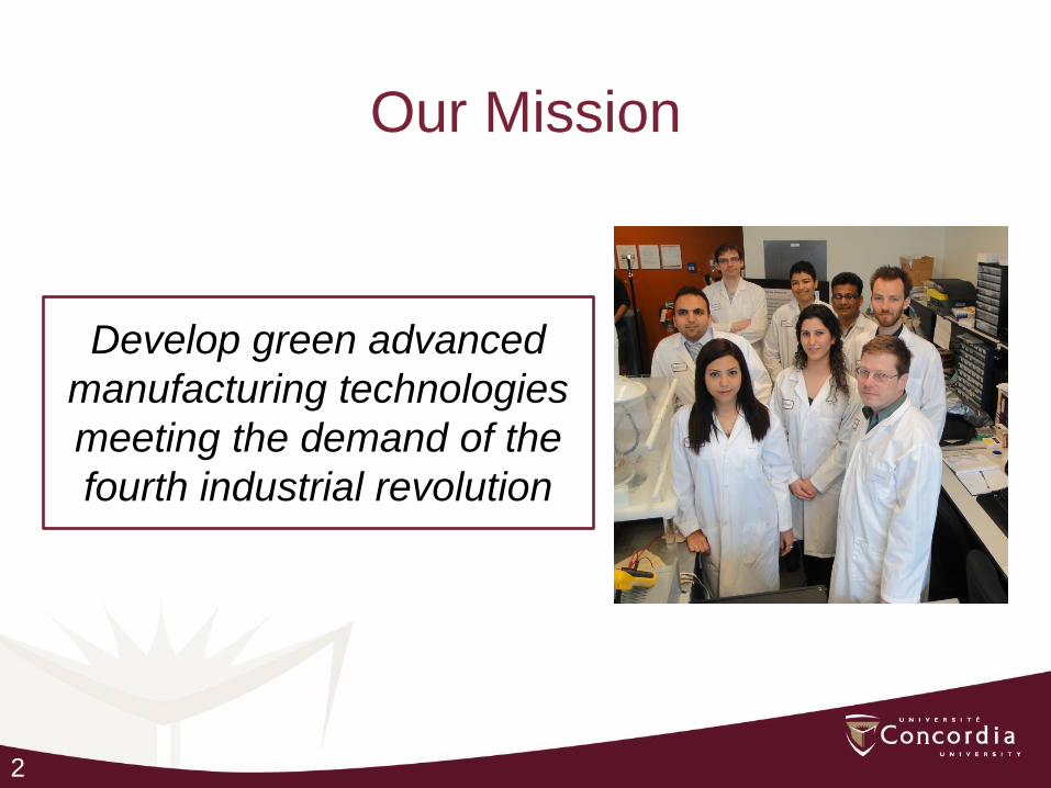
Our Mission
Develop green advanced
manufacturing technologies
meeting the demand of the
fourth industrial revolution
3
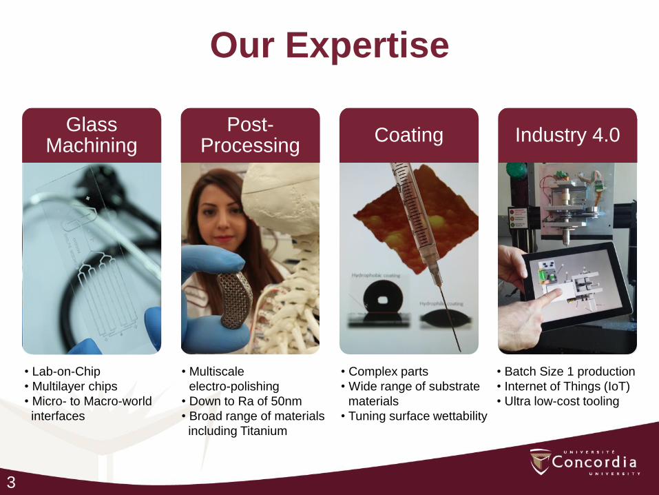
Our Expertise
Glass Machining
Post-Processing
Coating Industry 4.0
• Lab-on-Chip
• Multilayer chips
• Micro- to Macro-world
interfaces
• Multiscale
electro-polishing
• Down to Ra of 50nm
• Broad range of materials
including Titanium
• Complex parts
• Wide range of substrate
materials
• Tuning surface wettability
• Batch Size 1 production
• Internet of Things (IoT)
• Ultra low-cost tooling
4
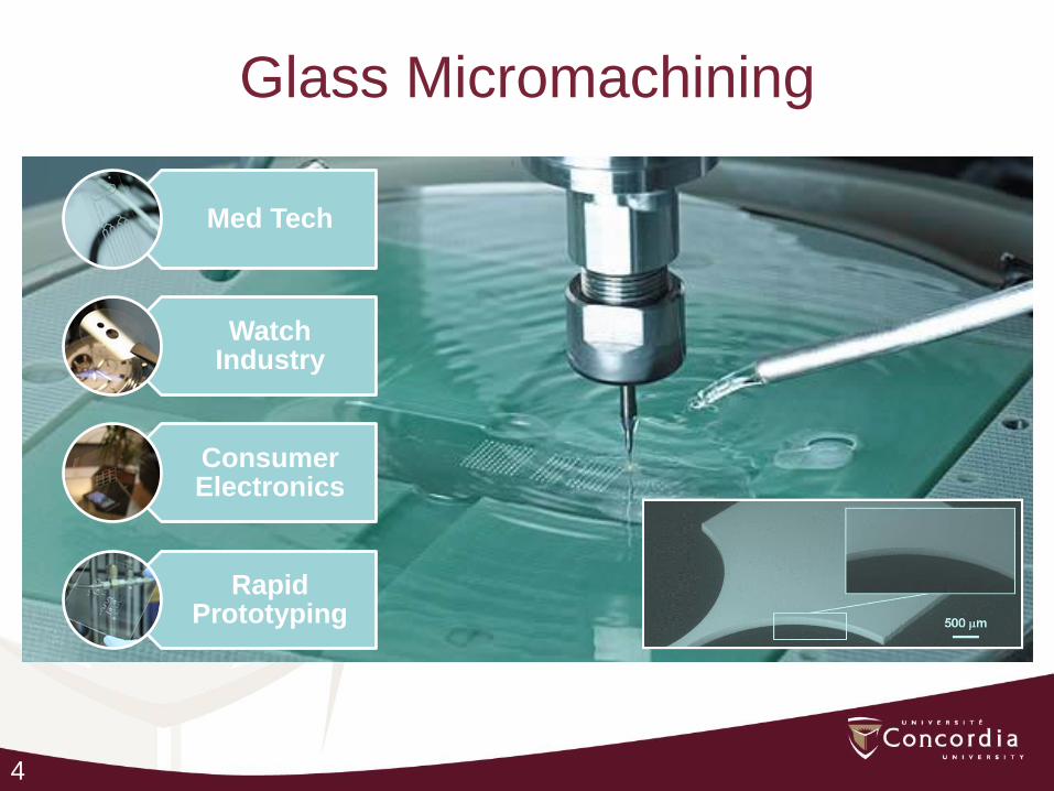
Glass Micromachining
Med Tech
Watch Industry
Consumer Electronics
Rapid Prototyping

5
Electropolishing
SLM part
Counter electrode (CE)
3D printed CE holder

6
Room Temperature Nanocoating
400 mm through glass via
Ni plated
Hydrophilic coating Hydrophobic coating
7
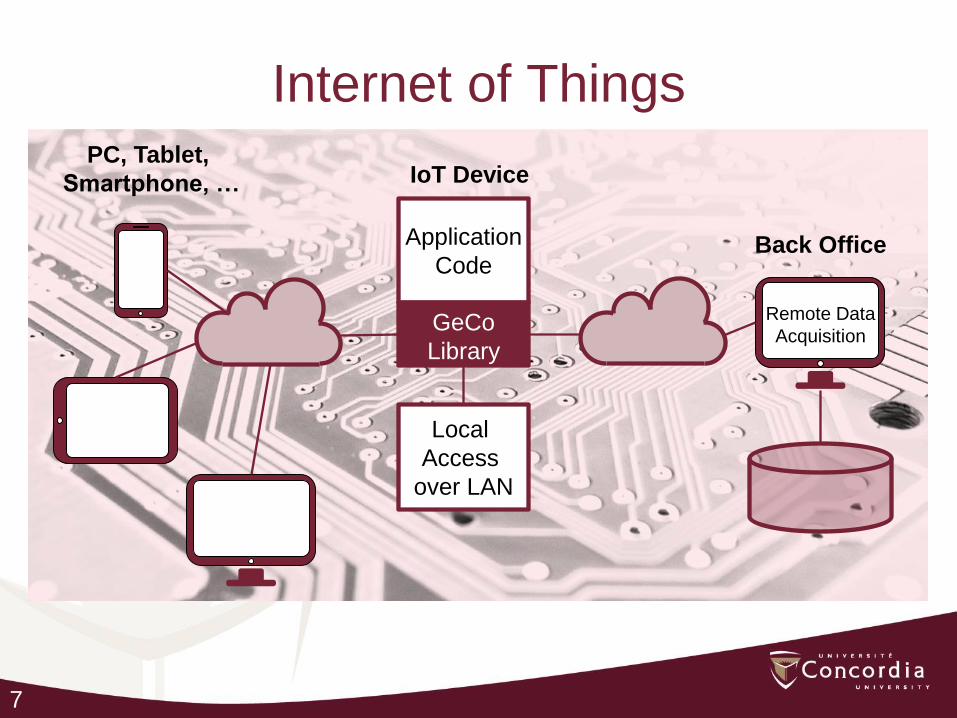
Internet of Things
Application
Code
GeCo
Library
IoT Device PC, Tablet,
Smartphone, …
Local
Access
over LAN
Back Office
Remote Data
Acquisition
8
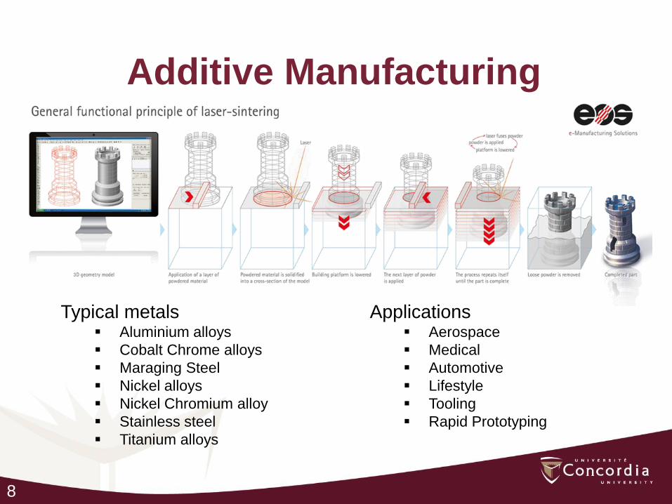
Additive Manufacturing
Typical metals Aluminium alloys
Cobalt Chrome alloys
Maraging Steel
Nickel alloys
Nickel Chromium alloy
Stainless steel
Titanium alloys
Applications Aerospace
Medical
Automotive
Lifestyle
Tooling
Rapid Prototyping
9
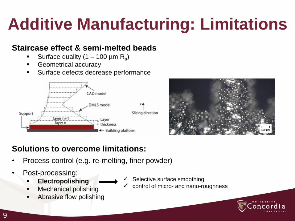
Additive Manufacturing: Limitations
Staircase effect & semi-melted beads Surface quality (1 – 100 µm Ra)
Geometrical accuracy
Surface defects decrease performance
100 µm
Solutions to overcome limitations:
• Process control (e.g. re-melting, finer powder)
• Post-processing: Electropolishing
Mechanical polishing
Abrasive flow polishing
Selective surface smoothing
control of micro- and nano-roughness
10
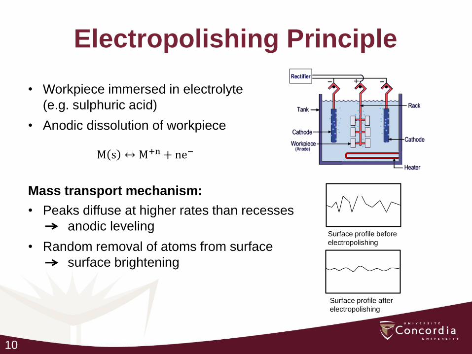
Electropolishing Principle
• Workpiece immersed in electrolyte
(e.g. sulphuric acid)
• Anodic dissolution of workpiece
Surface profile before
electropolishing
Surface profile after
electropolishing
Mass transport mechanism:
• Peaks diffuse at higher rates than recesses
anodic leveling
• Random removal of atoms from surface
surface brightening
M s ↔ M+n + ne−

11
Electropolishing Limitations
• Acts only on microprofiles (=> requires low initial surface roughness)
• Aqueous acidic solution limits removal of metal species
forming TiO2 layer stopping removal process
• Acidic electrolytes are very hazardous
Method to overcome limitations
• Pulse Technology control Nernst diffusion layer
• Water-free electrolytes

12
Nernst Diffusion Layer Evolution
Nernst diffusion layer control by pulsed current
• Short pulses reducing large asperities (> 100 µm)
Diffusion layer contours
both small and larger sized
asperities
Diffusion layer contours
only effectively larger sized
asperities
Diffusion layer no longer
contours any of the
asperities
t = 0 ms t = 0.06 ms t = 1 ms

13
Pulse Technology Effect of Pulse Width
Pulse Width [µs]
Ro
ugh
ne
ss S
a [µ
m]
14
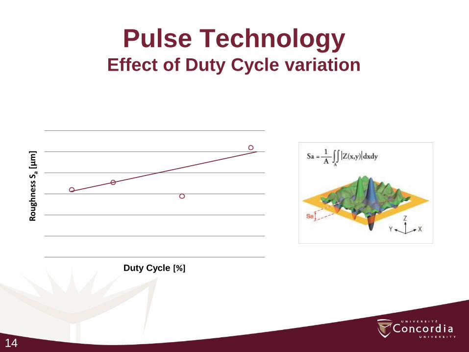
Pulse Technology Effect of Duty Cycle variation
Ro
ugh
ne
ss S
a [µ
m]
Duty Cycle [%]

15
Pulse Technology Effect of Polishing Time
Ro
ugh
ne
ss S
a [
µm
]
Polishing time [min]
16
-80.0
-60.0
-40.0
-20.0
0.0
20.0
40.0
60.0
80.0
0.0 0.5 1.0 1.5 2.0 2.5 3.0 3.5 4.0
[µm]
[mm]
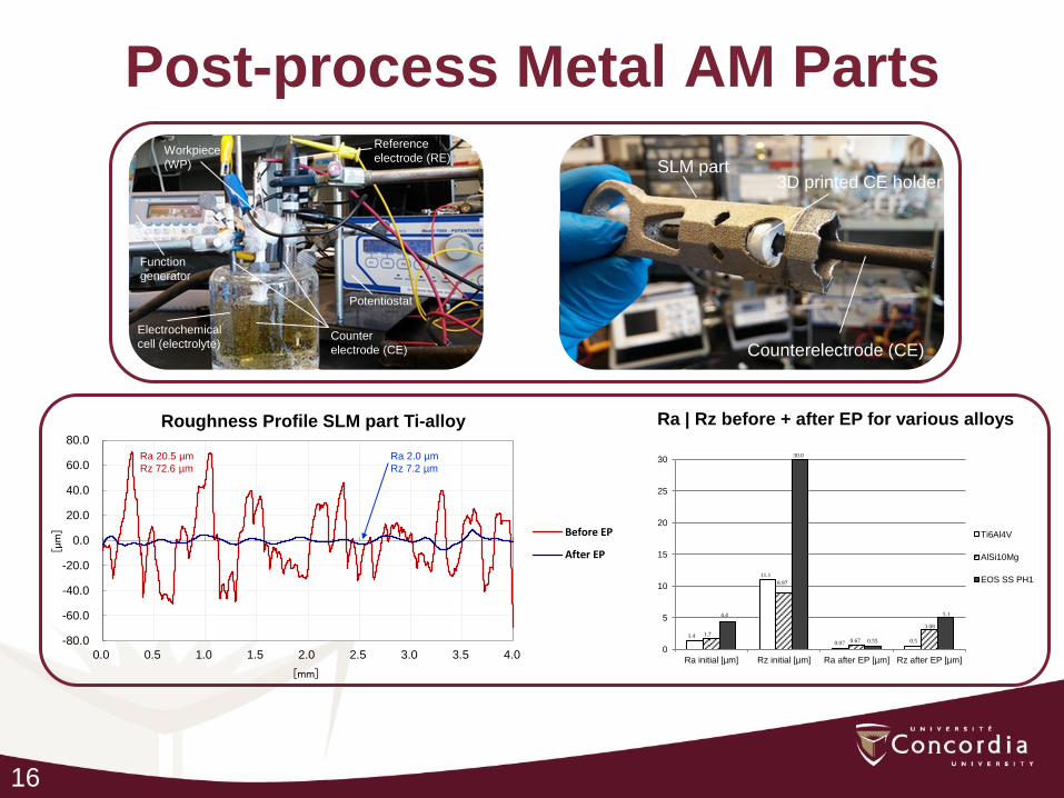
Roughness Profile SLM part Ti-alloy
Before EP
After EP
Post-process Metal AM Parts
0
5
10
15
20
25
30
Ra initial [µm] Rz initial [µm] Ra after EP [µm] Rz after EP [µm]
Ti6Al4V
AlSi10Mg
EOS SS PH1
1.4 1.7
4.4
11.1
8.97
30.0
0.07 0.67 0.55 0.5
3.08
5.1
Ra 2.0 µm
Rz 7.2 µm
Ra 20.5 µm
Rz 72.6 µm
Ra | Rz before + after EP for various alloys
SLM part
Counterelectrode (CE)
3D printed CE holder
Reference
electrode (RE) Workpiece
(WP)
Counter
electrode (CE)
Potentiostat
Function
generator
Electrochemical
cell (electrolyte)
17
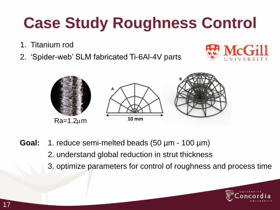
Case Study Roughness Control
1. Titanium rod
2. ‘Spider-web’ SLM fabricated Ti-6Al-4V parts
Goal: 1. reduce semi-melted beads (50 µm - 100 µm)
2. understand global reduction in strut thickness
3. optimize parameters for control of roughness and process time
A
.
B
.
10 mm Ra=1.2mm

18
Ti-rods Effect of Polishing Time
0
0.05
0.1
0.15
0.2
5 10 15 20 25 30 35
Ra
[m
m]
Polishing Time [min]
Ra=1.2mm

19
Ti-Spider Web Effect of EP on Bead Removal
Unpolished
Polished (35 min)
500mm
500mm
200mm
400mm
100mm
100mm
20
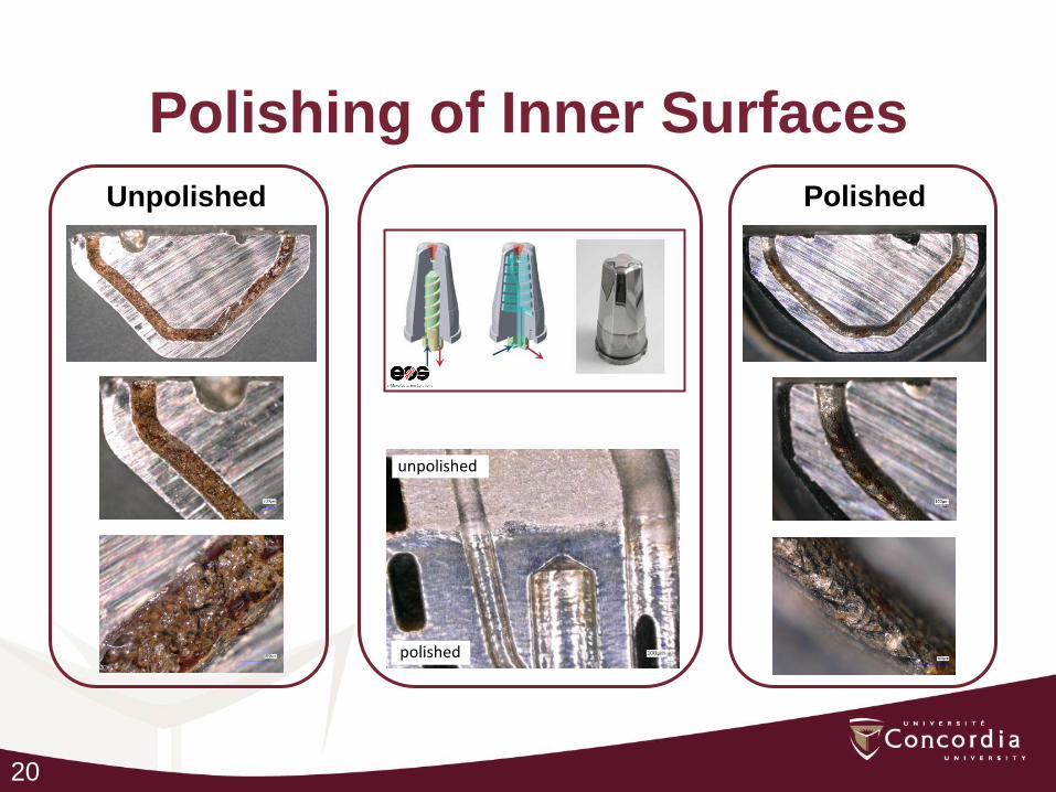
Polishing of Inner Surfaces
Unpolished Polished
unpolished
polished

21
Conclusions
• Pulse technology is an effective tool to eliminate surface
asperities on AM parts
• Surface roughness is reduced typically by a factor 10-20
• Possible to tune the final roughness
• Possible to polish complex shapes
• Possible to polish inner surfaces
22
Current industrial partners

23
What we offer
R&D projects
Laboratory analysis
Continuing education
Collaborative platforms

24
THANK YOU
Electrochemical Green Engineering Group
http://ege.encs.concordia.ca