multivendor sbrt/igrt the calypso 4d localization...
TRANSCRIPT

MultivendorMultivendor SBRT/IGRT SBRT/IGRT The Calypso 4D Localization and Tracking The Calypso 4D Localization and Tracking
System / System / ElektaElekta SynergySynergy--SS
ToufikToufik DjemilDjemil, Ph.D., Ph.D.Cleveland ClinicCleveland Clinic
Practical Medical Physics SymposiumPractical Medical Physics Symposium
AAPM 54AAPM 54thth Annual MeetingAnnual MeetingCharlotte, North Carolina Charlotte, North Carolina
August 02, 2012August 02, 2012

ObjectivesObjectives
• Understand operational and quality assurance aspects of Calypso combined with Synergy-S and Pinnacle TPS
• Understand the technical limitations of the hybrid system
• Describe clinical implementation of the system and typical cases treated

ObjectivesObjectives
• Understand the clinical rationale for localization and tracking
• Understand the necessity of hybrid technologies and systems
• Understand the physics behind the Calypso localization mechanism and its principles of operation

IntroductionIntroduction
• Dose escalation to the prostate increases local control
• Image guidance for accurate treatment delivery and intra-fraction motion monitoring is critical in this environment of dose escalation and hypo fractionation
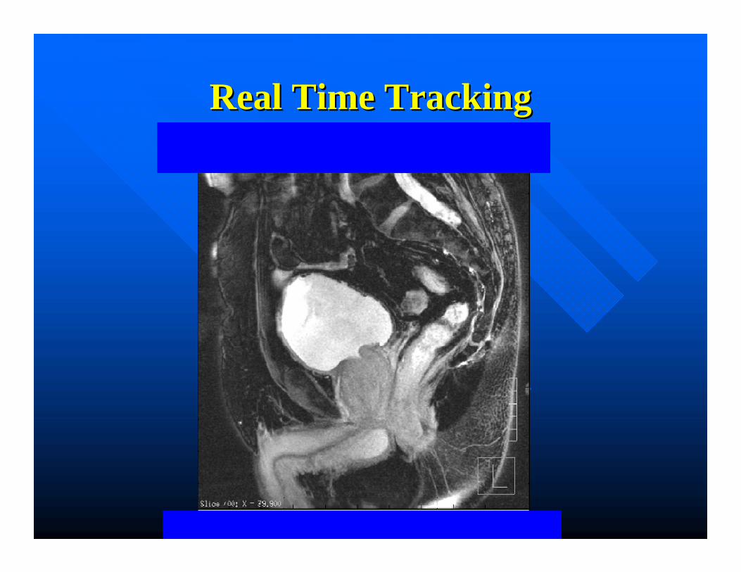
Real Time TrackingReal Time Tracking

Prostate Motion During TreatmentProstate Motion During Treatment
All (N=35) 1157 473 40.88 179 15.47
# % # %
Fractions with > 3mm excursion for >30 seconds
cumulative
Fractions with > 5mm excursion for >30 seconds
cumulativePatient ID# Fractions
Analyzed
C.A. Enke1, T. Solberg1, A. Mahadevan2, T. Djemil2 , P. Kupelian3, T. Willoughby3, G. Weinstein4, S. Jani4, N. Flores5, D. Liu5,
1Nebraska Medical Center, Omaha, NE, 2Cleveland Clinic, Cleveland, OH, 3M. D. Anderson Cancer Center Orlando, Orlando, FL, 4Sharp Memorial Hospital, San Diego, CA,
5Scottsdale Healthcare/Arizona Oncology Services, Scottsdale, AZ.

IGRTIGRT• Transabdominal ultrasound, KV X-rays, and KV/MV
CBCT
• Disavantages:Snapshots of the prostate positionNot available during radiation deliveryAdditional ionizing radiation exposure May be subjective and operator dependent in
acquisition and interpretation
• Option: Hybrid system used for prostate EBRT (IMRT/SBRT)

SynergySynergy--S/CalypsoS/Calypso

The Calypso 4D Localization The Calypso 4D Localization SystemSystem
• New technology using non ionizing AC electromagnetic (EM) field for locating and tracking patient tumors: the Calypso system.
• An intermitent EM pulse excite implanted wireless circuits called Beacon transponders
• The Beacons echo a distinct signal determining their coordinates

The Calypso 4D Localization The Calypso 4D Localization SystemSystem
• The Beacons’ coordinates are used to determine the translational shifts in the X, Y, Z directions to register the target to linacisocenter.
• Rotation of the target around the three directions is also determined.
• After patient setup, the system continouslytracks the position of the target in real time.
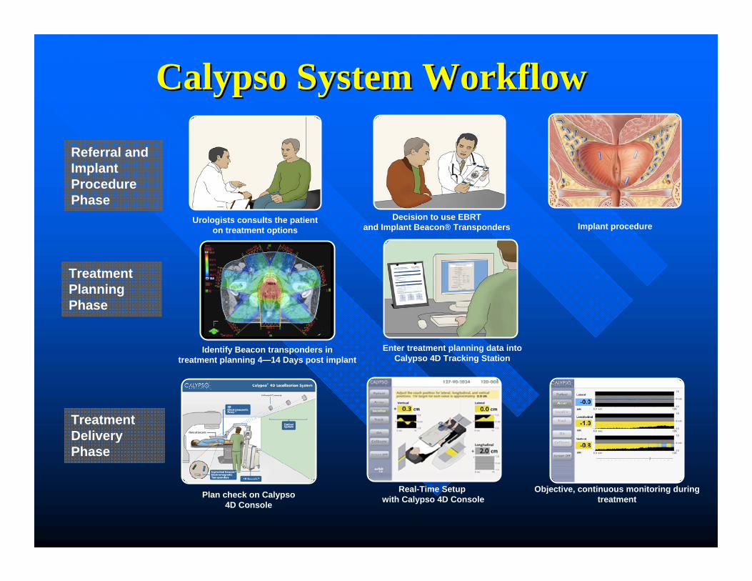
Urologists consults the patienton treatment options
Decision to use EBRTand Implant Beacon® Transponders Implant procedure
Referral and Implant ProcedurePhase
Plan check on Calypso 4D Console
Real-Time Setup with Calypso 4D Console
Objective, continuous monitoring during treatment
Treatment Delivery Phase
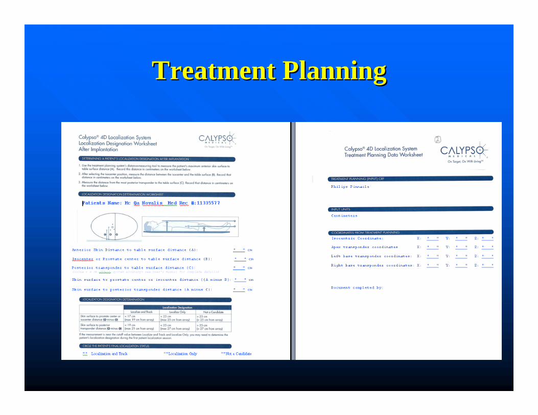
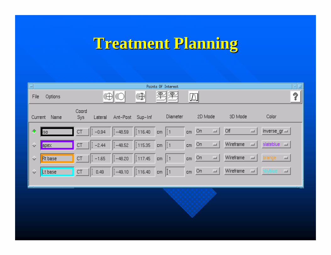
Enter treatment planning data into Calypso 4D Tracking Station
Treatment PlanningPhase
CalypsoCalypso System WorkflowSystem Workflow
Identify Beacon transponders in treatment planning 4—14 Days post implant

The Calypso 4D Localization The Calypso 4D Localization SystemSystem
• It consists of:• Beacon transponders• Console• Array• Optical cameras• Tracking station

Platform OverviewPlatform Overview
Beacon® TranspondersBeacon® Transponders
Tracking StationTracking Station
ConsoleConsole
Infrared Cameras
Optical Targets
Optical SystemOptical System
Electromagnetic Array™
Electromagnetic Array™

Beacon TranspondersBeacon Transponders
• Three Transponders Beacons are implanted under Ultrasound guidance
• 1.8mm x 8.5 mm (14 Gauge needle)
• When Excited with an EM pulse, they echo distinct signals used to determine their coordinates
• Coordinates used to locate target with respect to machine isocenter

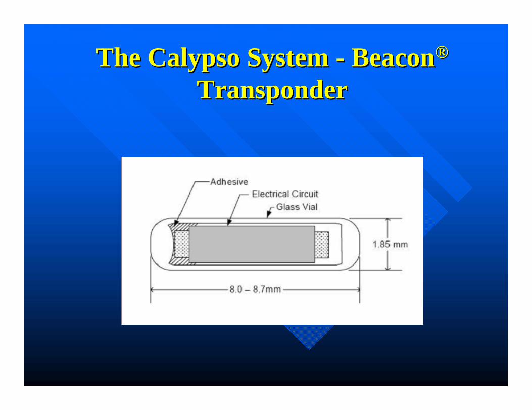
The Calypso System The Calypso System -- BeaconBeacon®®
TransponderTransponder
Wireless miniature Beacon® Electromagnetic Transponders
Wireless miniature Beacon® Electromagnetic Transponders
Actual size: ~8.5 mm
The Calypso System The Calypso System -- BeaconBeacon®®
TransponderTransponder
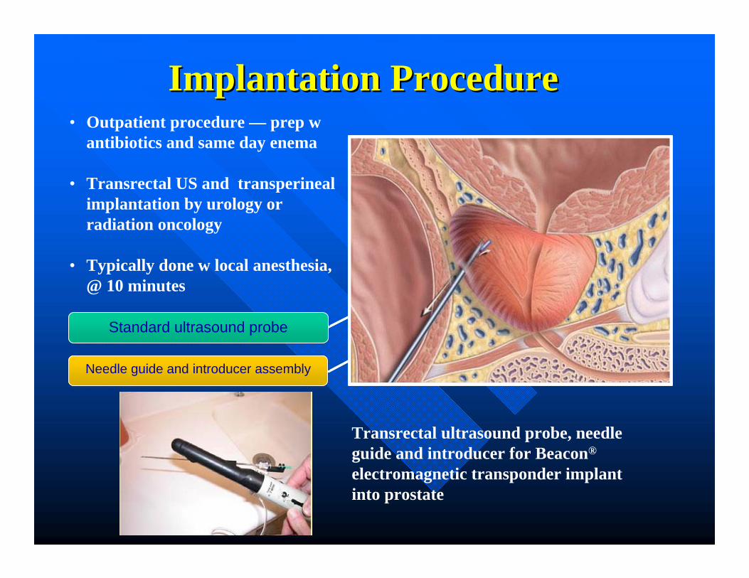
Implantation ProcedureImplantation Procedure• Outpatient procedure — prep w
antibiotics and same day enema
• Transrectal US and transperinealimplantation by urology or radiation oncology
• Typically done w local anesthesia, @ 10 minutes
Transrectal ultrasound probe, needle guide and introducer for Beacon®
electromagnetic transponder implant into prostate
Needle guide and introducer assemblyNeedle guide and introducer assembly
Standard ultrasound probeStandard ultrasound probe

ContraindicationsContraindications
• Anticoagulation/Antiplatelet (Implantation)
• Allergy to local anesthetics (Implantation)
• Implanted signaling devices (Pacemaker, neurostimulator, certain infusion devices) - Interaction with electromagnetic signal unknown
• Prosthetic hip or large metal implantation (Vascular grafts) near transponders
• AP diameter restrictions
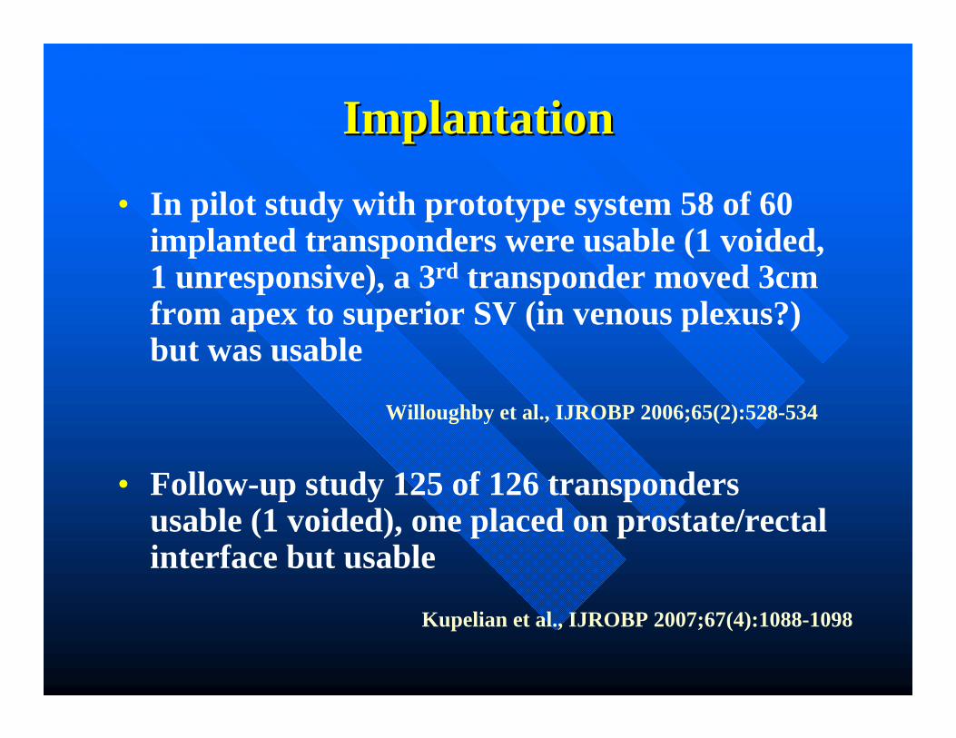
ImplantationImplantation
• In pilot study with prototype system 58 of 60 implanted transponders were usable (1 voided, 1 unresponsive), a 3rd transponder moved 3cm from apex to superior SV (in venous plexus?) but was usable
• Follow-up study 125 of 126 transponders usable (1 voided), one placed on prostate/rectal interface but usable
Kupelian et al., IJROBP 2007;67(4):1088-1098
Willoughby et al., IJROBP 2006;65(2):528-534

• On second study of 42 patients (125 transponders) mean SD of intratransponderdistances was 0.8 mm from day 4 to 80.
StabilityStability
Kupelian et al., IJROBP 2007;67(4):1088-1098

The Flat Panel ArrayThe Flat Panel Array• The array is an
extendible flat panel
• Contains the source coils that generate the EM signal
• Source coils emit frequencies between 275 and 550 kHz
• 1 to 2% attenuation

Flat Panel ArrayFlat Panel Array
Continuous, real-time monitoring of the prostate
Objective guidance enables clinician to manage organ motion
Accurate localization for maximum confidence
Non-ionizing technology for quick patient setup
Continuous, real-time monitoring of the prostate
Objective guidance enables clinician to manage organ motion
Accurate localization for maximum confidence
Non-ionizing technology for quick patient setup

Transponder SignalsTransponder Signals
• Transponders excited sequentially at each of three unique resonant frequencies
• Each transponder subsequently responds with a decaying magnetic field
• Process of excitation and sensing is repeated several hundred times to improve signal/noise for each transponder localization
Beacon® Electromagnetic Transponder
Actual size: ~ 8.5mm
Excitation Waveform
Sour
ce C
oil C
urre
nt
Response Waveform
Res
onat
or C
urre
nt
Excitation Phase Ring Down Phase
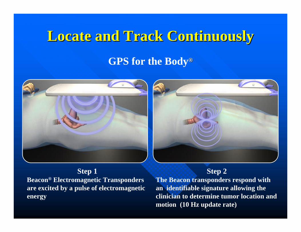
Locate and Track ContinuouslyLocate and Track ContinuouslyGPS for the Body®®
Step 2The Beacon transponders respond with an identifiable signature allowing the clinician to determine tumor location and motion (10 Hz update rate)
Step 1Beacon® Electromagnetic Transponders are excited by a pulse of electromagnetic energy

Unique Frequencies Identify LocationUnique Frequencies Identify Location
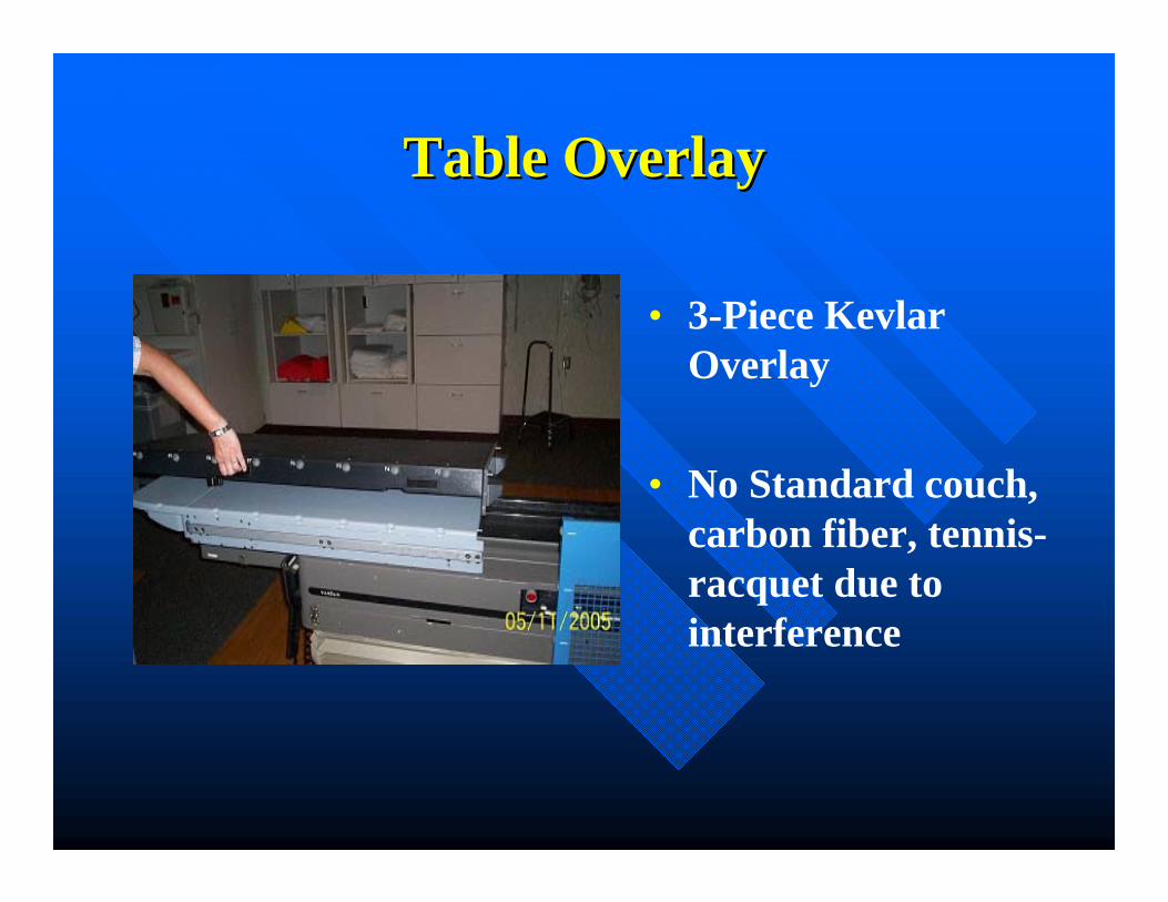
Table OverlayTable Overlay
• 3-Piece Kevlar Overlay
• No Standard couch, carbon fiber, tennis-racquet due to interference
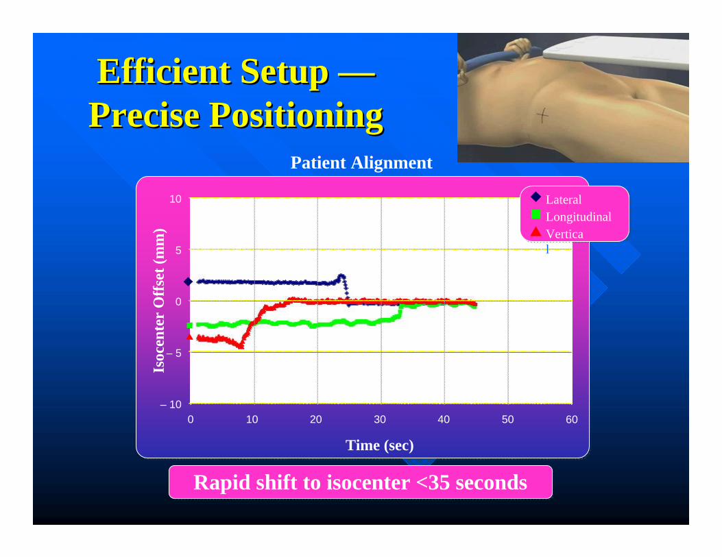
Efficient Setup Efficient Setup ——Precise PositioningPrecise Positioning
Patient Alignment
– 10
10
0 10 20 30 40 50 60
Time (sec)
Isoc
ente
rO
ffse
t (m
m)
– 5
0
5
LateralLongitudinalVertical
Rapid shift to isocenter <35 secondsRapid shift to isocenter <35 seconds

0
300
600
800
1000
Calypso System1 Ultrasound IGRT2 X-ray IGRT3 CBCT IGRT4
Setup Time (seconds)Se
tup
Tim
e in
Sec
onds
Setu
p T
ime
in S
econ
ds
100
200
400
500
700
108 s
336 s
474 s
720 s
900
Sources:1Calypso Medical Pivotal Study; 2Chandra et al, Int. J. Radiation Oncology Biol. Phys. Vol 56, No. 2, pp 436-447, 2003; 3Fox et al, J. Am Coll Radiol 2006;3:38-44; 4Ghilezan et al, Int. J. Radiation Oncology Biol. Phys. Vol 60, No. 5, pp 1602-1610, 2004
Disclaimer: This content is informational only and represents no promise or guarantee by Calypso® Medical regarding coverage, coding, billing and payment levels.
Efficient Setup
Calypso v US 1.6 v 3.7 min @ CCF, Warman et al., IJROBP 2007 69(3):S661

During Radiation Prostate is Constantly Monitored
From outside the treatment room, RTT can watch for “Out Of
Tolerance” indicator
From outside the treatment room, RTT can watch for “Out Of
Tolerance” indicator

Cleveland Clinic Prostate EBRTCleveland Clinic Prostate EBRT•• DoseDose: :
--LowLow--risk 76 risk 76 GyGy, 2 , 2 GyGy per fractionper fraction--IntInt & High& High--risk 78 risk 78 GyGy (66 (66 GyGy to proximal SV)to proximal SV)
•• PTVPTV::--Clarity or CBCT = CTV + 5 mm post, 8 mm Clarity or CBCT = CTV + 5 mm post, 8 mm
lat/ant/sup/lat/ant/sup/infinf--Calypso = CTV + 4 mm post, 6 mm lat/ant/sup/Calypso = CTV + 4 mm post, 6 mm lat/ant/sup/infinf
•• SimSim:Supine, empty rectum, full bladder, no specific Supine, empty rectum, full bladder, no specific
immobilization, immobilization, urethrogramurethrogram, no intra, no intra--rectal devicesrectal devices

• 1,765 EBRT treatments @ CCF from 1996-2003• All fractionations included (2Gy, 1.8Gy, 2.5Gy)

02468
1012
>=Grade1 >=Grade2
Late GU
0
5
10
15
>=Grade1 >=Grade2
Late GI
IGRT3D CRT
•• 1,765 EBRT treatments @ CCF from 19961,765 EBRT treatments @ CCF from 1996--2003.2003.•• All fractionations included (2Gy, 1.8Gy, 2.5Gy)All fractionations included (2Gy, 1.8Gy, 2.5Gy)
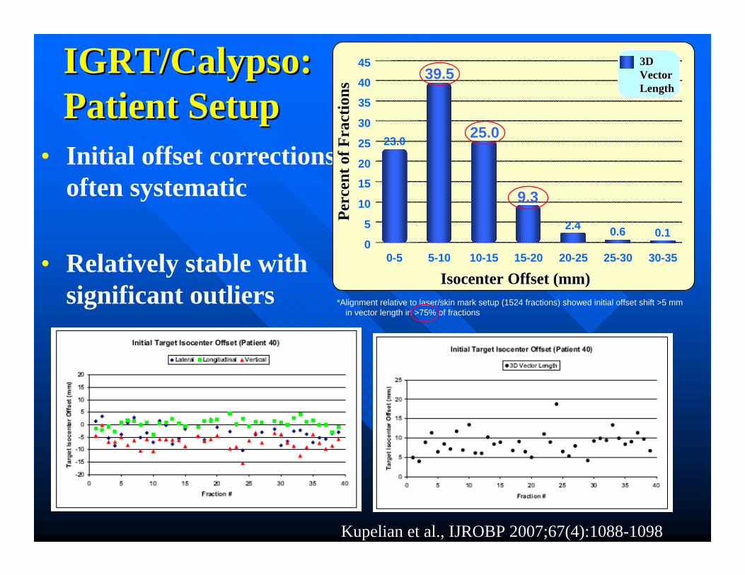
• Initial offset corrections often systematic
• Relatively stable with significant outliers
IGRT/Calypso:IGRT/Calypso:Patient SetupPatient Setup
Kupelian et al., IJROBP 2007;67(4):1088-1098
0
15
30
40
45
0-5 5-10 10-15 15-20 20-25
3D 3D VectorVectorLengthLength
25-30 30-35
IsocenterIsocenter Offset (mm)Offset (mm)
Perc
ent o
f Fra
ctio
nsPe
rcen
t of F
ract
ions
5
10
20
25
35
23.0
2.4 0.10.6
*Alignment relative to laser/skin mark setup (1524 fractions) showed initial offset shift >5 mm in vector length in >75% of fractions
39.5
25.0
9.3
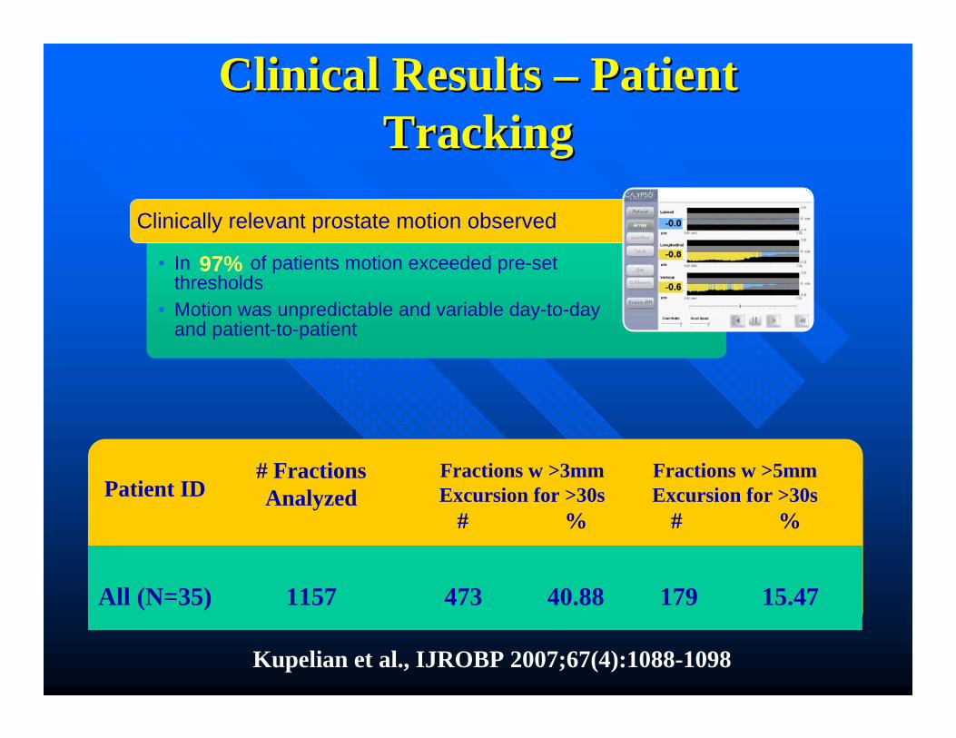
Clinical Results Clinical Results –– Patient Patient TrackingTracking
• In of patients motion exceeded pre-set thresholds
• Motion was unpredictable and variable day-to-day and patient-to-patient
Clinically relevant prostate motion observed
97%
Patient ID# Fractions Analyzed
All (N=35)
Fractions w >3mm Excursion for >30s
# %
Fractions w >5mm Excursion for >30s
# %
1157 473 40.88 179 15.47
Kupelian et al., IJROBP 2007;67(4):1088-1098

3D Variable Motion3D Variable Motion
Time (sec)
Isoc
ente
rO
ffse
t (m
m)
-20
-5
15
-15
-10
0
10
20
-18 60 120 180 240 300 360 420 480 540
5
LateralLongitudinalVertical

Clinical Results Clinical Results –– Patient TrackingPatient Tracking
Stable
Erratic Behavior
Continuous Drift
Transient Excursion
Persistent Excursion
High-Frequency Excursion
Kupelian et al., IJROBP 2007;67(4):1088-1098

How Much Interruption?How Much Interruption?
• Review of actions taken at 5 centers on multi-institutional study (35 patients)- Four used 5mm action threshold (998 fx)- One used 3mm action threshold (159 fx)
• Interventions in 36.2% of cases exceeding threshold, avg delay 35-120 seconds (interruption –realignment).
Enke et al., IJROBP 2006 66(3):S363
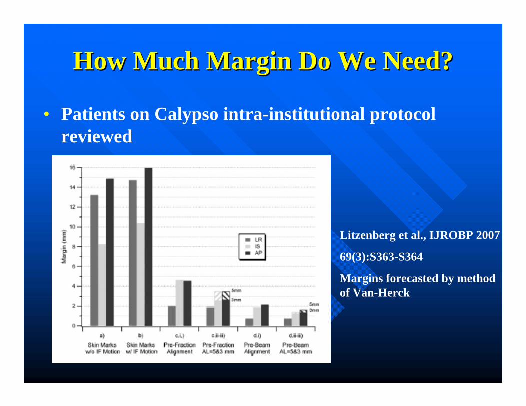
How Much Margin Do We Need?How Much Margin Do We Need?
• Patients on Calypso intra-institutional protocol reviewed
Litzenberg et al., IJROBP 2007
69(3):S363-S364
Margins forecasted by method of Van-Herck

Assessing the Impact of Margins Assessing the Impact of Margins (AIM) (AIM)
Outcomes Study PublicationOutcomes Study Publication• Published in Urology in May
2010
• Assessed effect of reduced treatment margins and real-time tracking on patient-reported quality of life (QOL), using previously published comparator cohort (Sanda et al, NEJM, 2008)
• Conclusion: AIM patients had significantly reduced acute GI, GU and some sexual symptoms compared to comparator cohort
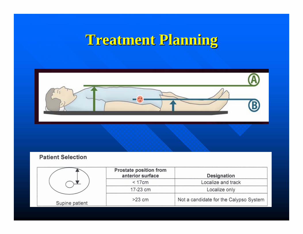
Treatment PlanningTreatment Planning
Treatment PlanningTreatment Planning
Treatment PlanningTreatment Planning

Generated ReportsGenerated Reports

Generated ReportsGenerated Reports

QAQA
• Camera Calibration• Quarterly• L -Frame fixture• T-Frame fixture
• System Calibration• Daily and Monthly• Isocenter fixture

Camera CalibrationCamera Calibration

System CalibrationSystem Calibration
Calibrate Calypso coordinate reference frame to Machine isocenter (treatment room laser positions).
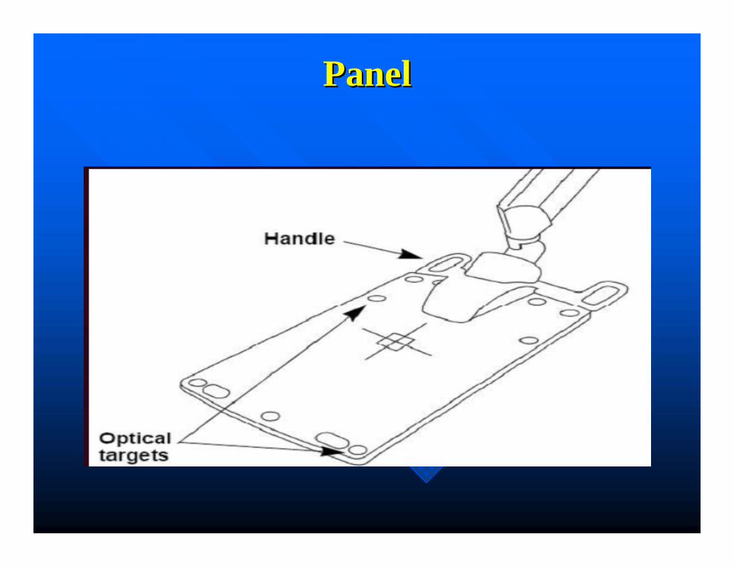
PanelPanel

CalibrationCalibration

HorizonsHorizons
•• Dynamic Dose ReconstructionDynamic Dose Reconstruction•• PostPost--prostatectomyprostatectomy•• HypoHypo--fractionated prostate SBRTfractionated prostate SBRT•• Lung CancerLung Cancer•• Breast CancerBreast Cancer•• Pancreatic CancerPancreatic Cancer•• Spine SBRTSpine SBRT

Prostate SBRTProstate SBRTRTOG 0938RTOG 0938
• 36.25 Gy in 5 Fx• 2 Fx / week, 3 to 4 days apart • 5 or more IMRT non-coplanar beams or VMAT• 6 or 10 MV• Fiducials, and possibly rectal balloon to immobilize the
prostate• GTV = CTV = Prostate• PTV = CTV + 5 mm (3 mm Post)• Prescription dose (PD) to at least 99% of prostate and
95% of PTV• Max dose within PTV </= 7% above PD• Urethra visualization required if max dose > 38.78 Gy• If Tx time > 7 min, need tracking or repeat IGRT

Prostate SBRTProstate SBRTDoseDose--Escalation Study (Timmerman)Escalation Study (Timmerman)
• 45, 47.5, and 50 Gy in 5 Fx• Min 36 h between fractions• 6 to 15 MV Tomotherapy or Trilogy• IMRT with Tissue Heterogeneity on• Markers (gold seeds or Calypso) implanted 1 week before sim• 60-100 cc rectal balloon• Urethra delineated with flexible catheter in sim• CBCT before each fraction to confirm fiducials, ballon, and filling
of bladder • PTV = Prostate + 3 mm• Prescription dose (PD) to at least 95% of PTV• Urethra, Bladder wall and Ant Rectal Wall Max Dose </= 105% of
PD
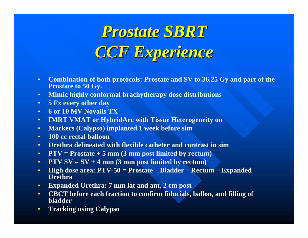
Prostate SBRTProstate SBRTCCF ExperienceCCF Experience
• Combination of both protocols: Prostate and SV to 36.25 Gy and part of the Prostate to 50 Gy.
• Mimic highly conformal brachytherapy dose distributions• 5 Fx every other day• 6 or 10 MV Novalis TX• IMRT VMAT or HybridArc with Tissue Heterogeneity on• Markers (Calypso) implanted 1 week before sim• 100 cc rectal balloon• Urethra delineated with flexible catheter and contrast in sim• PTV = Prostate + 5 mm (3 mm post limited by rectum)• PTV SV = SV + 4 mm (3 mm post limited by rectum)• High dose area: PTV-50 = Prostate – Bladder – Rectum – Expanded
Urethra• Expanded Urethra: 7 mm lat and ant, 2 cm post• CBCT before each fraction to confirm fiducials, ballon, and filling of
bladder• Tracking using Calypso

ProstateProstate
• Prostate implanted with calypso transponders
• Balloon inserted during the sim
• High risk area delineated
• 36.5 Gy in 5 fx QED• 50 Gy HRA• Use VMAT or Hybrid
arcs

ProstateProstate

Spine SBRT (with instrumentation)Spine SBRT (with instrumentation)
• Tested in acrylic phantom with up to 6 cm of medium density bone slabs (1.6g/cm3) or up to 2 cm bone cement.
• Tracking accuracy <0.5 mm for 30 second tracking demos.
Djemil et al., IJROBP 2007 69(3):S2105
Lung and Spine (Clinical Phase I)Lung and Spine (Clinical Phase I)
• Calypso transponders successfully implanted into 4 spine and 2 lung SBRT patients
• Position of transponders verified by kV X-ray prior to treatment- All 4 spine cases remained stable- One lung case stable, other pt evacuated transponder
• All 6 patients tracked successfully. Spine transponders approached maximum distance for tracking (25 cm).
Willoughby et al., IJROBP 2008 72(1):S642-S643

Breast CancerBreast CancerUse Surface Transponder For Motion Monitoring During Treatment• Single patient, multiple use• Place on skin mark and align with lasers• Use orientation indicator + setup notes to ensure correct device
orientation• Confirm patient set-up with alternate alignment method (lasers
and tattoos, SSD measurements or imaging)
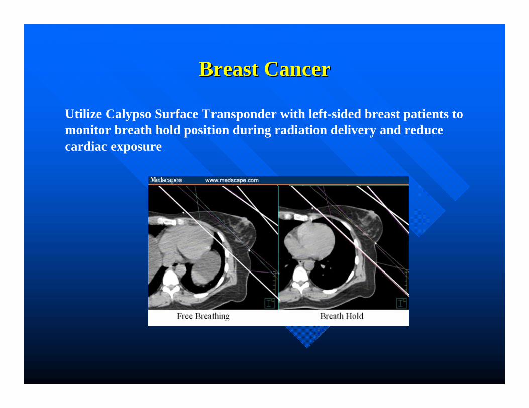
Breast CancerBreast Cancer
Utilize Calypso Surface Transponder with left-sided breast patients to monitor breath hold position during radiation delivery and reduce cardiac exposure

AcknowledgementsAcknowledgements
•• Kevin Stephens, M.D.Kevin Stephens, M.D.•• Arul Arul MahadevanMahadevan, M.D., M.D.•• Patrick Patrick Kupelian,MKupelian,M. D.. D.•• Lisa Levine/CalypsoLisa Levine/Calypso
