multiweave, innovative technology for multiaxial technical
TRANSCRIPT
Multiweave, innovative technology for multiaxial technical fabrics
Mário Lima
Centre for Mechanical and Materials Technologies, University of Minho, Guimarães, Portugal [email protected]
Abstract
Technical textiles are products for applications where technical performance is of paramount importance for a
wide range of applications, such as the reinforcement of composite materials in aircraft fuselages, boat hulls,
and many others. The aim of this work was to investigate the feasibility of a multiaxial 2D interlaced woven
structure able to provide specified strengths in different directions and the development of its manufacturing
process. This structure is obtained by the insertion of interlaced yarns at approximately 45º between the weft
and warp. A multiaxial weaving system was designed comprising the following systems: warp feeding, bias
yarns feeding and criss-cross insertion, shedding, incorporating one heddle, weft feeding and insertion, beating-
up mechanism, incorporating the reed, fabric taking-up and winding mechanisms. The solution incorporates the use of conventional weaving elements but also completely new mechanisms or modifications of existing ones. As
a conclusion, the Multiweave prototype developed within this work is being used to produce different types of
Directionally Oriented Structures, using various types of fibres (HT polyester, aramide, carbon and glass) and
yarn counts.
Keywords: Weaving; Multiaxial structures; Technical textiles.
1 Introduction
1.1 State of the art
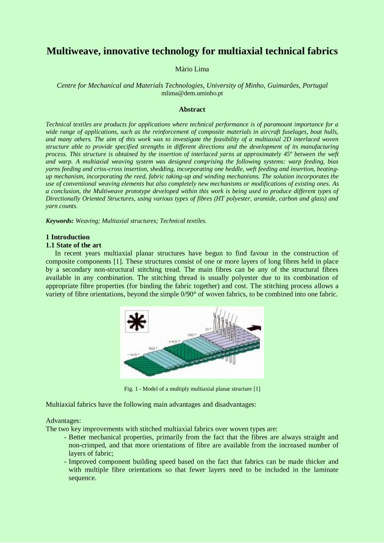
In recent years multiaxial planar structures have begun to find favour in the construction of
composite components [1]. These structures consist of one or more layers of long fibres held in place by a secondary non-structural stitching tread. The main fibres can be any of the structural fibres
available in any combination. The stitching thread is usually polyester due to its combination of
appropriate fibre properties (for binding the fabric together) and cost. The stitching process allows a
variety of fibre orientations, beyond the simple 0/90° of woven fabrics, to be combined into one fabric.
Fig. 1 - Model of a multiply multiaxial planar structure [1]
Multiaxial fabrics have the following main advantages and disadvantages:
Advantages:
The two key improvements with stitched multiaxial fabrics over woven types are:
- Better mechanical properties, primarily from the fact that the fibres are always straight and non-crimped, and that more orientations of fibre are available from the increased number of
layers of fabric;
- Improved component building speed based on the fact that fabrics can be made thicker and with multiple fibre orientations so that fewer layers need to be included in the laminate
sequence.

Disadvantages:
- Polyester fibre does not bond very well to some resin systems and so the stitching can be a
starting point for wicking or other failure initiation;
- The fabric production process can also be slow and the cost of the machinery high. This, together with the fact that the more expensive, low tex fibres, are required to get good surface
coverage for the low weight fabrics, means the cost of good quality, stitched fabrics, can be
relatively high compared to wovens; - Extremely heavy weight fabrics, while enabling large quantities of fibre to be incorporated
rapidly into the component, can also be difficult to impregnate with resin without some
automated process; - The stitching process, unless carefully controlled, can bunch together the fibres, particularly in
the 0° direction, creating resin-rich areas in the laminate;
- Poor delaminating strength due to non-interlacement between layers.
On the other hand, several efforts to produce multiaxial interlaced fabrics have been made in the
past, which is reported in several patents, namely:
- European Patent Application 0263392 A2, of 1988, [2] describes a so-called machine for
tetraxial weaving; - European Patent Specification EP0571461B1 of 1992, [3] describes a multiaxial weaving
machine;
- United States Patent 5351722 dated of 1994, [4] describes a weaving machine for manufacturing of a tetraxial fabric;
- European Patent WO 03/012184 A2 of 2003 [5] describes a tetraxial fabric and a machine for
its manufacture; - European Patent WO 2004/0059054 A1 of 2004 [6] describes a multi-axial fabric and a
weaving machine for its production.
These patents propose different solutions for the problem of bias yarns feeding and criss-crossing, but no one has proved to be sufficiently good for the construction of either a reliable neither a
commercial multiaxial weaving machine.
1.2 Motivation and objectives
Following earlier work [7], the motivation of this research was to develop a new manufacturing
process that could take advantage of the possibilities of new woven structures. One of the most important characteristics of technical textiles is the possibility of providing a specified strength in
multiple directions. To achieve this objective the research was oriented towards the development of a
new concept that could produce a multiaxial fabric. This kind of fabric is designed to boost the
reinforcement in bias directions, by the insertion of interlaced yarns between the weft and warp in a woven structure. Therefore, the main objectives were:
1. The design and development of a Multiaxial Weaving Machine incorporating mechanisms,
systems and components for guiding, warp yarns, weft yarns and bias yarns toward a multiaxial fabric formation area;
2. The resulting product, the multiaxial fabric.
1.3 Applications The use and impact of multiaxial fabrics may be found in two different types of products:
1. Technical textiles, such as reinforcements for hard or flexible composites for the car and
aircraft industry, conveyor belts, inflatable boats, sails, boat hulls, air inflated houses, geotextiles, wall coverings, sport devices, tarpaulins, tents, grinding and lapping disks and
many other applications on products that still use traditional technology of gluing together
several layers of fabrics, differently oriented. 2. Garments designed to be resistant to tear, with an original texture, easily conformable and
dimensionally stable, could have a big impact on very different articles such as military and
protective clothing. Although the application on conventional clothing looks considerably out

of the way, possible applications on tennis and other sports shoes and some sportswear seems
a possibility to further explore.
2 The model The Multiweave fabric is obtained by interlacing 4 sets of yarns, the warps (blue), the wefts (green)
and other two sets of bias yarns at +45 and -45 degrees (red) as shown in figure 2.
Fig. 2 - Geometric model of the Multiweave fabric
3 The development prototype The main specifications for the design of the limited scale Multiweave development prototype were
defined according to the available technical capabilities. The resulting Multiweave machine, partially
represented in figure 3, comprises the following elements: - Bias yarns feeding system;
- Mechanism for the criss-cross insertion of the bias yarns;
- Warping system;
- Shedding system incorporating a special heddle design; - Weft insertion system;
- Beating-up mechanism, incorporating a special reed design;
- Fabric taking-up system.
Fig. 3 - Multiweave development prototype
A detail of the fabric formation area is shown in figure 4, where the shed, the weft insertion needle
and part of the bias yarns feeding system are visible.

Fig. 4 - Multiweave development prototype - detail of the fabric formation area
4 Working principle
The Multiweave working principle is as follows: The bias yarns are feed from two bias beams
through a tension compensation device and stepwise moved in two very close parallel layers in opposite directions by means of an appropriate mechanism. The heddle and the reed are respectively in
their lower and backward positions, bellow the plane of the bias yarns, allowing their free lateral criss-
crossing. The heddle raises the warps to form the shed and at the same time the warps interlace with the bias. The shed is therefore formed between the warps and the two very close parallel layers of the
bias yarns. A first (false) beating takes place to clear the shed; this was found necessary as when the
warp yarns are raised by the heddle, they are partially held up by the criss-crossing effect of the bias, preventing from obtaining a clear shed. The weft yarn is then inserted to be interlaced with the warps
and the bias yarns as shown in figure 5; a second (real) beating operation takes place which compacts
the fabric, at the same time that the heddle moves down to its rest position closing the shed and
holding the weft. The taking-up mechanism advances one step and the fabric is wound-up.
Fig. 5 - Multiweave - detail of shed, bias criss-crossing and weft insertion
During the development process, all synchronization has been achieved mechanically to help
getting to a working prototype faster. Therefore, all movements are mechanically driven from a main shaft with the help of cam and intermittent mechanisms. With all the mechanical systems sufficiently
developed, the required torque in the main shaft could be measured. Consequently the most important
decisions such as choosing the driving motor and the frequency inverter were made. The control system is based on an ARM MCU microcontroller board with embedded software designed to control

the motor for speed regulation. Other functionalities were also incorporated but not used in this first
prototype such as detection of emergency stops, broken weft, warp and bias yarns, strained weft. The
main user interface options include: Total fabric produced, fabric produced since the machine was
turned on or the last counter reset, average speed (mm/s) since the machine was turned on or since the last counter reset, motor’s main shaft speed in rpm, number of emergency stops, total emergency's
down-time and the ability of programming the production of a certain amount of fabric.
5 Experimental
5.1 Multiweave fabric samples
Multiaxial fabric samples of different fibres were manufatured using the Multiweave development prototype. A preliminary study of the fabrics obtained and their mechanical behaviour has already
been carried out [8]. Table 1 presents the dimensional properties of the fabrics used to undertake this
research.
Table 1 – Dimensional properties of Multiweave fabric samples
Figures 6 to 8 represent details of three types of multiaxial woven fabrics produced.
Fig. 6 - Multiweave fabric sample n.º 1
Fig. 7 - Multiweave fabric sample n.º 2
Sample 1 Sample 2 Sample 3
Bias Warp Weft Bias Warp Weft Bias Warp Weft
Material PES PES Aramid PES PES PES PES PES Carbon
Yarn linear
density
(dtex)
1100/2
1100/2
2200
1100/2
1100/2
1100/4
1100/2
1100/2
8000
Density
(yarns/cm) 2,16 2,03 2,93 2,10 2,04 2,91 2,25 2,02 2,99
Crimp (%) 4,05 7,05 2,80 3,67 4,20 4,42 0,58 6,94 6,6
Mass (g/m2) 448,52 563,32 767,86
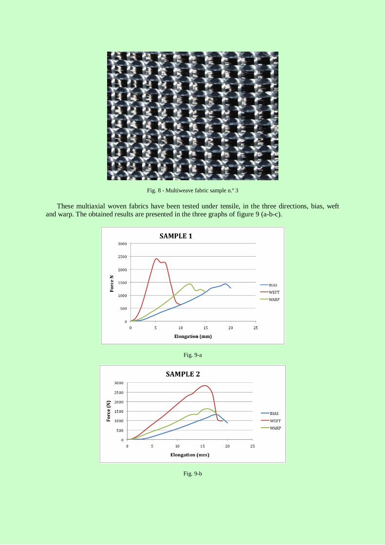
Fig. 8 - Multiweave fabric sample n.º 3
These multiaxial woven fabrics have been tested under tensile, in the three directions, bias, weft and warp. The obtained results are presented in the three graphs of figure 9 (a-b-c).
Fig. 9-a
Fig. 9-b
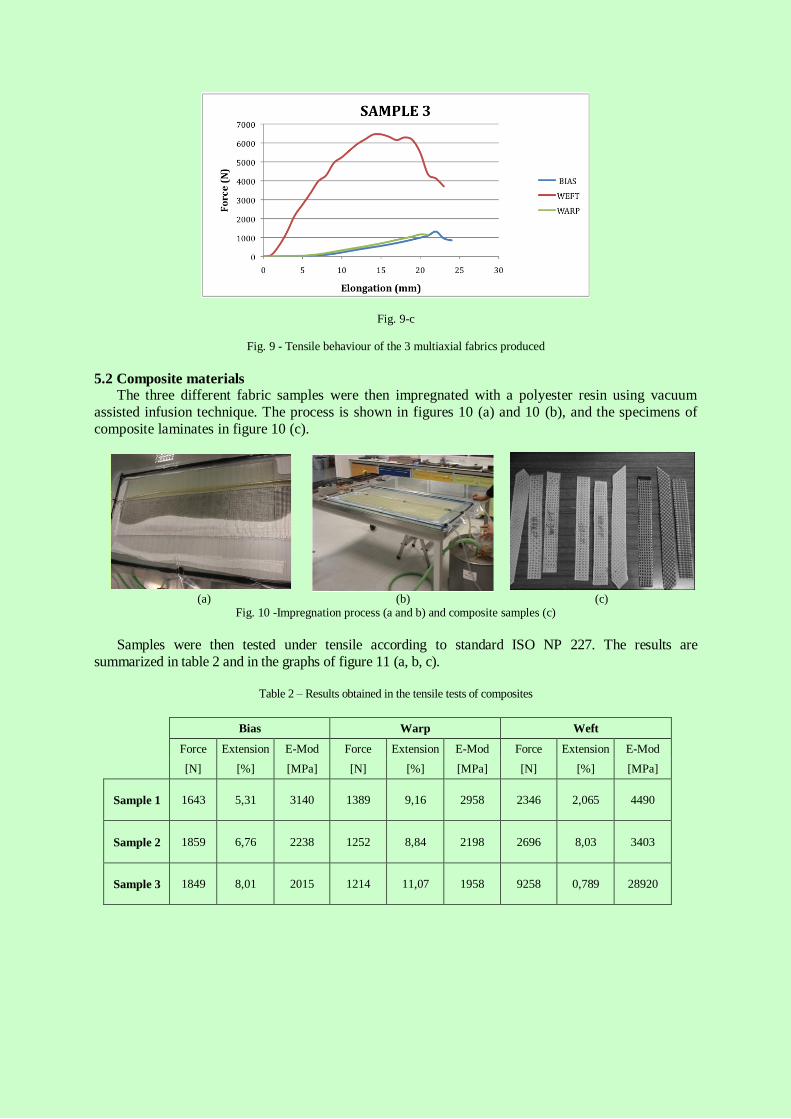
Fig. 9-c
Fig. 9 - Tensile behaviour of the 3 multiaxial fabrics produced
5.2 Composite materials The three different fabric samples were then impregnated with a polyester resin using vacuum
assisted infusion technique. The process is shown in figures 10 (a) and 10 (b), and the specimens of
composite laminates in figure 10 (c).
(a) (b) (c) Fig. 10 -Impregnation process (a and b) and composite samples (c)
Samples were then tested under tensile according to standard ISO NP 227. The results are
summarized in table 2 and in the graphs of figure 11 (a, b, c).
Table 2 – Results obtained in the tensile tests of composites
Bias Warp Weft
Force Extension E-Mod Force Extension E-Mod Force Extension E-Mod
[N] [%] [MPa] [N] [%] [MPa] [N] [%] [MPa]
Sample 1
1643 5,31 3140 1389 9,16 2958 2346 2,065 4490
Sample 2
1859 6,76 2238 1252 8,84 2198 2696 8,03 3403
Sample 3
1849 8,01 2015 1214 11,07 1958 9258 0,789 28920

Fig. 11 (a)
Fig. 11 (b)
Fig. 11 (c)
Fig. 11 - Force-extension curves for the composite materials produced
Analyzing the obtained results it is possible to conclude that the reinforcing material used in the
weft direction is greatly influencing the tensile performance of the composite material. In fact, in the
other directions, i.e., warp and bias, as the material is always the same (HT PES) all samples present a very similar behaviour.
6 The second generation machine Fabrics produced by the development prototype presented a structure which was not yet very
dense, mainly due to the limitations imposed by the relatively high bias pitch. From the experience
aquired from the initial reseach, a joint venture was established between one of the industrial partners of the project and the University of Minho in order to design and manufature a second generation
machine. New specifications were decided, mainly for the fabric width that was raised from 200 to
500 mm and the pitch of the warp and bias yarns that was lowered from 5 to 4 mm. This new machine
has recently started its running tests and so far has showed a great improvement over the previous one.
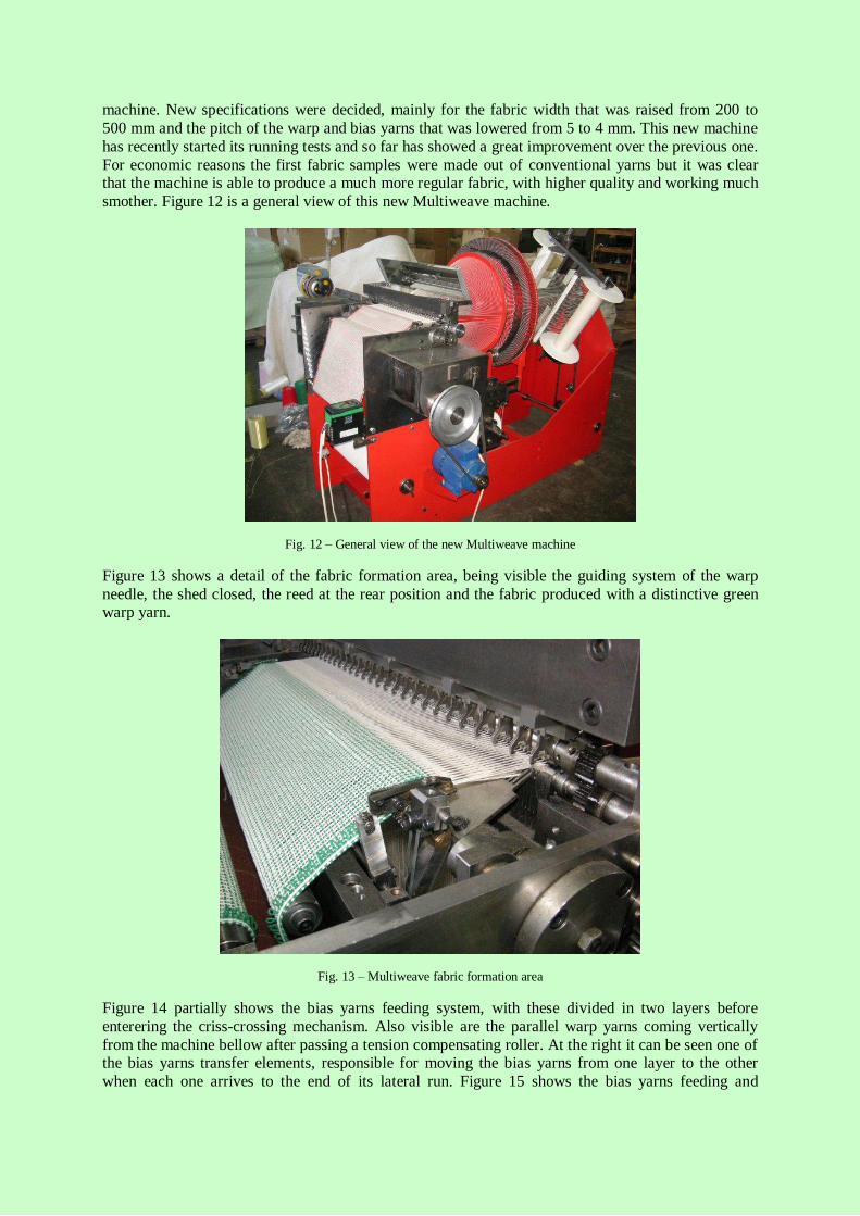
For economic reasons the first fabric samples were made out of conventional yarns but it was clear that the machine is able to produce a much more regular fabric, with higher quality and working much
smother. Figure 12 is a general view of this new Multiweave machine.
Fig. 12 – General view of the new Multiweave machine
Figure 13 shows a detail of the fabric formation area, being visible the guiding system of the warp
needle, the shed closed, the reed at the rear position and the fabric produced with a distinctive green warp yarn.
Fig. 13 – Multiweave fabric formation area
Figure 14 partially shows the bias yarns feeding system, with these divided in two layers before
enterering the criss-crossing mechanism. Also visible are the parallel warp yarns coming vertically
from the machine bellow after passing a tension compensating roller. At the right it can be seen one of the bias yarns transfer elements, responsible for moving the bias yarns from one layer to the other
when each one arrives to the end of its lateral run. Figure 15 shows the bias yarns feeding and
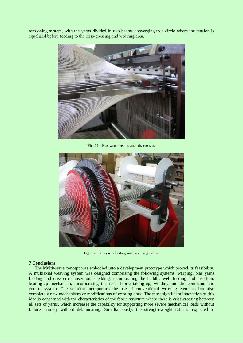
tensioning system, with the yarns divided in two beams converging to a circle where the tension is
equalized before feeding to the criss-crossing and weaving area.
Fig. 14 – Bias yarns feeding and crisscrossing
Fig. 15 – Bias yarns feeding and tensioning system
7 Conclusions The Multiweave concept was embodied into a development prototype which proved its feasibility.
A multiaxial weaving system was designed comprising the following systems: warping, bias yarns
feeding and criss-cross insertion, shedding, incorporating the heddle, weft feeding and insertion, beating-up mechanism, incorporating the reed, fabric taking-up, winding and the command and
control system. The solution incorporates the use of conventional weaving elements but also
completely new mechanisms or modifications of existing ones. The most significant innovation of this idea is concerned with the characteristics of the fabric structure where there is criss-crossing between
all sets of yarns, which increases the capability for supporting more severe mechanical loads without
failure, namely without delaminating. Simultaneously, the strength-weight ratio is expected to

increase, which, for applications such as in the aircraft and car industries can be very advantageous.
Other important applications are in marine textiles, such as composites for boat and shipbuilding,
which are products submitted to severe stressing conditions. The main result is the Multiweave
prototype which is being used to produce different types of DOS, Directionally Oriented Structures, using various types of fibres (HT polyester, aramide, carbon and glass) and yarn counts.
The industrial importance of this study is expected to be exploited by the technical textiles sector,
mainly in textile reinforced composites for high technological applications, replacing, with advantages, the existing technique of using several layers of fabrics, differently oriented, to achieve a
higher isotropic behaviour.
The results obtained for the composite laminates produced with the multiaxial woven fabrics, were largely influenced by the type of the fibre used in the weft direction and by the yarns density of the
fabric.
Acknowledgments The author is grateful to the European Commission, VI Framework Programme for funding project
MULTIWEAVE COOP-CT-2003-1-508125. Thanks are also due to all partners of the consortium for
their efforts during the development of MULTIWEAVE project, with a particular reference to the P& Maia company and the enthusiasm and expertise of Mr. António Costa in the design and construction
of the machines. Last but not least, thanks to various research workers that contributed to this
outcome, namely Mariana Banea, Raul Fangueiro and João Velosa.
References
[1] Published courtesy of David Cripps, Gurit, http://www.gurit.com.
[2] Ogahara, Kazumasa; Tsuboi, Reijiro; Ogahara Michihiro, “Tetraxial woven fabrics and tetraxial weaving machine thereof”, European Patent Application 0263392 A2.
[3] Mood, Geoffrey Ingles; Mahboubian-Jones, Malcom Gawayne, “Multiaxial Weaving” European
Patent Specification EP0571461 B1 of 1992. [4] Mamiilano, DINI “Tetraxial fabric and weaving machine for its manufacture” United States
Patent 5351722 dated of 1994.
[5] Mamiilano, Dini, “Tetraxial fabric and machine for its manufacture” European Patent WO
03/012184 A2 dated of 2003. [6] Mário Araújo, Mário Lima, Multi-axial fabric and weaving loom for its production. European
Patent WO 2004/0059054 A1 dated of 2004.
[7] Mário Araujo, Mário Lima, Nuno Costa, MULTITEX New Weaving Concept for Multiaxial Fabric, TECNITEX 2001, 1st Autex Conference on Technical Textiles: Designing Textiles for
Technical Applications, Póvoa de Varzim, Portugal, June 27th and 28th 2001.
[8] Mário Lima, Raul Fangueiro, António Costa, Christian Rosiepen, Válter Rocha, “Multiweave – A prototype weaving machine for multiaxial technical fabrics”, Indian Journal of Fibre & Textile
Research, Vol. 34, March 2009, pp. 59-63.
Correspondence
For more information please contact:
Prof. Mário Lima CT2M - Centre for Mechanical and Materials Technologies University of Minho
Departament of Mechanical Engineering
4800-058 Guimarães
Portugal