muon tomography: plans for observations in the lesser antilles
TRANSCRIPT

Earth Planets Space, 62, 153–165, 2010
Muon tomography: Plans for observations in the Lesser Antilles
Dominique Gibert1, Francois Beauducel1, Yves Declais2, Nolwenn Lesparre1,Jacques Marteau2, Florence Nicollin3, and Albert Tarantola1∗
1Institut de Physique de Globe de Paris, UMR 7154 CNRS/INSU, Universite Paris Cite,4 Place Jussieu, Case 89, 75252 Paris cedex 5, France
2Institut de Physique Nucleaire de Lyon, UMR 5822 CNRS/IN2P3, Domaine scientifique de la Doua,4 Rue Enrico Fermi, 69622 Villeurbanne cedex, France
3Geosciences Rennes, UMR 6118 CNRS/INSU, B15 Campus de Beaulieu, 35042 Rennes cedex, France
(Received November 23, 2008; Revised June 25, 2009; Accepted July 10, 2009; Online published February 22, 2010)
The application of muon tomography to monitor and image the internal structure of volcanoes in the LesserAntilles is discussed. Particular focus is directed towards the three volcanoes that fall under the responsibility ofthe Institut de Physique du Globe of Paris, namely La Montagne Pelee in Martinique, La Soufriere in Guadeloupe,and the Soufriere Hills in Montserrat. The technological criteria for the design of portable muon telescopes arepresented in detail for both their mechanical and electronic aspects. The detector matrices are constructed withscintillator strips, and their detection characteristics are discussed. The tomography inversion is presented, andits distinctive characteristics are brie y discussed. Details are given on the implementation of muon tomographyexperiments on La Soufriere in Guadeloupe.Key words: Volcanoes, monitoring, tomography, Martinique, Guadeloupe, Montserrat, telescope, muons, cosmicrays.
1. IntroductionLesser Antilles is a subduction volcanic arc within which
a dozen of either potentially or presently active volca-noes are located in populated areas (Fig. 1) (Lindsay etal., 2005). These examples are Martinique (La MontagnePelee), Guadeloupe (La Soufriere), and Montserrat (TheSoufriere Hills), whose volcanoes have presented an erup-tive activity since the beginning of the 20th century. The lastactivity of La Montagne Pelee occurred in 1929 (Romer,1931), i.e., 27 years after the catastrophic 1902 eruptionwhich killed 29,000 people (Lacroix, 1904). In Guade-loupe, La Soufriere had two phreatic eruptive episodes in1956 (Jolivet, 1958) and 1976–1977 (Le Guern et al., 1980;Feuillard et al., 1983), and this later event motivated theevacuation of nearly 73,000 persons during a 6-month pe-riod. The Soufriere Hills in Montserrat is presently in amagmatic eruption phase which started in 1995 and hassince devastated most of the island (Druitt and Kokelaar,2002).
Because of their societal impacts, these volcanoes aresubject to careful monitoring, and fully functional observa-tories have been installed in their vicinity for this purpose.Besides operating a network of classical techniques, likeseismic, chemical, or ground deformation monitoring, theseobservatories also provide unique privileged places for de-
∗Deceased on December 6, 2009.
Copyright c© The Society of Geomagnetism and Earth, Planetary and Space Sci-ences (SGEPSS); The Seismological Society of Japan; The Volcanological Societyof Japan; The Geodetic Society of Japan; The Japanese Society for Planetary Sci-ences; TERRAPUB.
doi:10.5047/eps.2009.07.003
veloping and testing new methods which could ultimatelybe integrated into the monitoring panoply.
The aim of volcanological monitoring is to evaluate thepresent state of the volcano within its eruption cycle, esti-mate its evolution in the near future, and quantify the asso-ciated risk for surrounding inhabitants. In practice, variousmethods and techniques must be carried on, and a numberof unknowns still remain in our current body of knowledgeof physical and chemical processes that lead to an eruption.
Quantifying an eruption hazard amounts to imaging thevolcano interior (structures and plumbing system geometry)and estimating the different source parameters (variationsof volume, density, strain, or pressure) associated with uidtransports (magma, gas, or water) or physical and chemi-cal evolution of the volcanic materials (e.g., hydrothermalalteration). Geophysical and geochemical techniques usedon volcanoes may all lead to estimates of these parameters,sometimes with direct measurements, mostly with model-ing and strong hypothesis.1.1 Volcano monitoring in the Lesser Antilles
Volcanoes in the Lesser Antilles have a very short periodof historical data compared to their mean eruption cycle ofhundreds of years, and most of the volcanoes had very fewobserved magmatic eruptions (Lindsay et al., 2005). Thisis a major dif culty in terms of monitoring and hazard as-sessment since the long-time baselines are not suf cientlyconstrained. We focus here on the three active volcanoeswhose monitoring is under the responsibility of France andwhere muon tomography is planned in a near future (Fig. 2):Mt. Pelee in Martinique, La Soufriere in Guadeloupe, andSoufriere Hills in Montserrat (co-responsibility with theSeismic Research Centre of Trinidad). These three volca-
153

154 D. GIBERT et al.: MUON TOMOGRAPHY AT LESSER ANTILLES VOLCANOES
Fig. 1. Location of Lesser Antilles islands and active volcanoes addressedin this paper.
noes are at the present time in three different states: dor-mant, early unrest activity, and ongoing magmatic eruption,respectively.
La Montagne Pelee (Fig. 2(F)) is presently in a quiet statesince the two last magmatic eruptions of 1902 and 1929–1932. The last fumaroles ceased to be active in 1970, andthe surface hydrothermal spots currently existing are threelow-temperature thermal springs located on the volcanoflanks. Seismic volcanic activity is also very weak, withless than 30 events per year (magnitudes lower than 1.7, fewkilometers deep), and there is no detectable ground defor-mation. Permanent survey allows the present volcanic stateto be diagnosed with confidence: no significant magmaticactivity at depth, and no eruptive phenomena expected inthe next years. Consequently, the alert level is maintainedat level 1 (i.e., green). Nevertheless, the magma chamberis probably being slowly fed from a deeper supply, but withneither detectable overpressure nor secondary effects, whilethe shallow hydrothermal system is in a steady state. Cur-rent instrumental observations at La Montagne Pelee can beused as a baseline before any eruption precursor signs.
La Soufriere of Guadeloupe (Fig. 2(E)) is in a more se-rious state. Its last magmatic eruption is estimated to havebeen 1530 AD (Boudon et al., 2008; Komorowski et al.,2008) and, since then, six phreatic eruptions have occurred:1690, 1797–1798, 1812, 1836–1837, 1956, and 1976–1977.The last unrest was interpreted as a still-born magmaticeruption by Feuillard et al. (1983) (see also Villemant et
al., 2005). A renewal of activity started in 1992, and sev-eral parameters are currently slowly increasing: intensifica-tion of shallow seismicity with long-period events, spatialextension and flux increase of the fumarolic activity at thesummit of the volcano, changes in the chemical composi-tion of the gas (sulfur and chlorine), and increases the tem-perature at several hydrothermal spots. These changes mo-tivated raising the alert level from level 1 (green) to level2 (yellow). Observations at La Soufriere of Guadeloupeshould allow any signs associated with the evolution of thehydrothermal system to be detected, as well as precursorsof a possible eruption in the next years, which should likelybe a phreatic type. Among the three volcanoes described inthis paper, La Soufriere of Guadeloupe is the first volcanowhere muon tomography is presently being implemented(more details are given in Section 4.1).
The Soufriere Hills (Fig. 2(D)) on-going magmatic erup-tion started in 1995, after a long period of dormancy sincethe previous magmatic eruption dated in the 17th century(Lindsay et al., 2005). The current activity pattern leads toalternated periods of rapid or slow lava dome growth, partialor total dome collapses, pyroclastic flows, and ash explo-sions. These various phenomena have resulted in the totaldestruction of the southern half of the island, including thecapital city Plymouth, which is currently covered by severaltens of meters of debris deposits. On June 25, 1997, a largepyroclastic flow killed 19 people and destroyed the island’sairport (Baxter et al., 2005). The total volume of magmaerupted is estimated to be 9×10⁸ m3 (Elsworth et al., 2008)for a maximum rate of lava dome of 10 m3 s−1 in some peri-ods. Two major dome collapses occurred in 2003 involvingapproximately 210×106 m3 of material (Herd et al., 2005),and the last one occurred in 2006 with 90×106 m3. Both ofthese initiated a small tsunami over the Guadeloupe coast(see http://www.mvo.ms for detailed information). Obser-vations at Soufriere Hills provide a unique opportunity inthe Lesser Antilles to monitor magmatic activity at the sur-face.1.2 Interest of muon tomography
Muon radiography was recently successfully used to im-age the density structure of volcanoes (Tanaka et al., 2005,2007a, b, 2008; Tanaka and Yokoyama, 2008). This tech-nique measures the flux of muons of cosmic origin and itsattenuation due to the screening by the rock volume. Theattenuation is directly related to the quantity of matter (ex-pressed in kg m−2) encountered by the muons along theirpath across the volcano. Muon radiography consequentlyconstitutes a unique way to obtain direct information onthe density distribution of geological objects. In practice,a muon radiograph is obtained by measuring the flux ofmuons crossing the volcano and arriving at the detector indifferent horizontal and vertical directions. These directionsspan the solid angle corresponding to the angular apertureof the telescope.
Knowledge of the density distribution inside a volcanois particularly important in terms of constraining its me-chanical behavior in case of flank collapse. For example,a volcano like La Soufriere has been partly damaged byboth phreatic explosions, which opened fractures, and byhydrothermal acid fluids, which transformed the original

D. GIBERT et al.: MUON TOMOGRAPHY AT LESSER ANTILLES VOLCANOES 155
DE
F
Fig.
2.L
ocat
ion
ofL
esse
rA
ntill
esis
land
sw
ithth
eir
activ
evo
lcan
oes
cons
ider
edin
this
pape
r.A
)M
onts
erra
t:T
heSo
ufri
ere
Hill
s(D
)sh
own
in20
08an
din
itscu
rren
tst
ate
ina
mag
mat
icer
uptio
n(h
ttp://
ww
w.m
vo.m
s).
B)
Gua
delo
upe:
La
Souf
rier
e(E
)sh
own
duri
ngits
last
phre
atic
erup
tion
in19
76an
dits
curr
ent
stat
ein
anin
crea
sing
activ
itype
riod
.C
)M
artin
ique
:L
aM
onta
gne
Pele
e(F
)cu
rren
tlyin
quie
tsta
tesi
nce
itsla
stm
agm
atic
erup
tion
in19
29–1
932.
Bla
ckst
ars
indi
cate
lava
dom
espo
sitio
ns.G
ray
tria
ngle
sar
epe
rman
ento
bser
vato
ries
.Thi
nar
row
sin
dica
teap
prox
imat
evi
ewan
gles
ofea
chph
otog
raph
.L
evel
lines
are
100-
min
terv
als
(Dig
italE
leva
tion
Mod
elfr
omSh
uttle
Rad
arTo
pogr
aphy
Mis
sion
data
base
).
156 D. GIBERT et al.: MUON TOMOGRAPHY AT LESSER ANTILLES VOLCANOES
volcanic rocks (andesite, ashes) into hydrothermalized ma-terial. Knowing the most affected parts of the volcano is ofa primary importance to be able to estimate both the vol-ume of rock potentially involved and the areas exposed inthe case of ank destabilization. For this, a global den-sity tomography of the volcano is necessary. Time monitor-ing is also necessary to follow density variations associatedwith uid movements in the volcano and possibly related toliquid/vapour transformation in the shallow hydrothermalsystem. With respect to volcanoes in a magmatic eruptionstate like the Soufriere Hills, muon radiography could bean interesting alternative to radar techniques (Wadge et al.,2008) for real-time monitoring of dome growth and even-tual collapse. Indeed, muon radiography would be an all-weather operational technique unaffected by the opacity ofash clouds and electrostatic discharges. Also, muon tele-scopes can be operated in deep caves, a location that pro-vides ef cient protection against ash and block fall.
The DIAPHANE project was launched at the beginingof 2008 to initiate and promote muon tomography in theFrench Earth Science and Particle Physics communities.The rst objectives of the project were to make technolog-ical choices for the muon telescopes and to de ne a de-sign suitable for the dif cult eld conditions encounteredon tropical volcanoes. Telescopes have been constructedand are now being tested. These points are developed in thenext sections with a particular emphasis on La Soufriere ofGuadeloupe where preliminary eld operations have beenundertaken to prepare for the installation of the telescopes.
2. Design of Muon Telescopes2.1 General design and mechanical concept
Several environmental factors make the eld conditionvery dif cult on tropical volcanoes such as La Soufriere ofGuadeloupe. Heavy rain necessitates careful waterproo ngof the telescopes, and rough topography necessitates the useof rope access techniques and helicopter hauling. This putsstrong constraints on both the size and the weight of theelements of the telescopes whose design must be modular.A practical rule of thumb is to have each part of the tele-scope weighing no more than a person, i.e. ≈80 kg so thatclassical rescue techniques, like Tyrolean systems, operatedby a small number of persons can be used to move and in-stall the telescopes. This approach also enables the use ofthe helicopter winches also designed for rescue operations.The mechanical parts of the telescopes must also be adapt-able to the local topography in order to allow an accuratepositioning of the detectors with respect to the target of theradiography experiment.
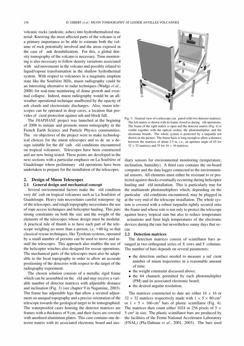
The chosen solution consists of a metallic rigid framewhich can be assembled on the eld and may receive a vari-able number of detector matrices with adjustable distanceand inclination (Fig. 3) (see chapter 9 in Nagamine, 2003).The frame has adjustable legs that allow a secured adjust-ment on unequal topography and a precise orientation of thetelescope towards the geological target to be tomographied.The waterproofed cases housing the detector matrices areframes with a thickness of 9 cm, and their faces are coveredwith anodized aluminium plates. This case contains one de-tector matrix with its associated electronic board and aux-
Fig. 3. General view of a telescope con gured with two detector matrices.The left matrix is shown with its frame closed as during eld operations.The frame of the right matrix is open and the detector matrix (Fig. 4) isvisible together with the optical cookie, the photomultiplier, and theelectronic boards. The whole system is protected by a tarpaulin notshown on the picture. The frame basis is long enough to allow a distancebetween the matrices of about 2.5 m, i.e., an aperture angle of 65 for32 × 32 matrices and 35 for 16 × 16 matrices.
iliary sensors for environmental monitoring (temperature,inclination, humidity). A third case contains the on-boardcomputer and the data logger connected to the environmen-tal sensors. All elements must either be resistant to or pro-tected against shocks eventually occurring during helicopterhauling and eld installation. This is particularly true forthe multianode photomultipliers which, depending on theparticular eld conditions encountered, may be plugged inat the very end of the telescope installation. The whole sys-tem is covered with a robust tarpaulin tightly secured ontothe frame and whose role is not only to protect the telescopeagainst heavy tropical rain but also to reduce temperature
uctuations and limit high temperatures of the electronicdevices during the rare but nevertheless sunny days that oc-cur.2.2 Detection matrices
The detection matrices consist of scintillator bars ar-ranged in two orthogonal series of X rows and Y columns.The number of bars depends on several parameters:
• the detection surface needed to measure a suf cientnumber of muon trajectories in a reasonable amountof time;
• the weight constraint discussed above;• the 64 channels permitted by each photomultiplier
(PM) and its associated electronic board;• the desired angular resolution.
The matrices constructed to date are either 16 × 16 or32 × 32 matrices respectively made with 1 × 5 × 80-cm3
or 1 × 5 × 160-cm3 bars of plastic scintillator (Fig. 4).The matrices then count either 1024 or 256 pixels of 5 ×5 cm2 in size. The plastic scintillator bars are produced bythe facilities of the Fermi National Accelerator Laboratory(FNAL) (Pla-Dalmau et al., 2001, 2003). The bars used

D. GIBERT et al.: MUON TOMOGRAPHY AT LESSER ANTILLES VOLCANOES 157
Fig. 4. View of two 16×16 matrices. The optical plugs are visible on twosides of each matrix and are to be connected to the clear bers guidingthe light onto the channels of the photomultiplier. The thickness of thematrices is 27 mm and their individual total weight is 20 kg.
in the present study have a cross-section of 1 × 5 cm2 andhave with both a hole for WLS ber insertion and a TiO2
re ective coating. Bars of 160 cm in length were deliveredby FNAL to construct the 32 × 32 matrices. Some of thesebars were cut to assemble the 16 × 16 matrices. The weightof a 32 × 32 matrix is ≈70 kg and that for a 16 × 16 matrixis ≈20 kg.
The WLS and clear bers are of the type Bicron BCF-91A MC and BCF-98 MC, respectively, both with a diam-eter of 1 mm. The WLS bers are inserted into the centralduct running along the center of the bars. In order to in-crease the photo-electron yield, the bers are glued alongtheir whole length with the BC-600 optical cement. A re-
ecting coating is placed at the free end of the ber in orderto further increase the yield (Pla-Dalmau et al., 2005). Theother end of the WLS ber is connected to optical connec-tors embedded in the scintillator bar. The connectors havebeen specially designed to either ensure the coupling of theWLS bers with the clear bers which transmit the greenlight to the cookie receiving the PM or to receive solid-state silicon photomultipliers for future replacement of thepresently used multianode photomultipliers. When a muonhits the detector matrix, the X and Y bars whose intersec-tion forms the pixel crossed by the particle emit UV lightwhich is in turn captured by their WLS bers inserted intheir duct. The visible green light produced by the WLS
ber is transmitted to a clear ber connected to a channel ofthe PM.
A cookie is a box with 64 clear bers connecting the clearbers coming from the bars to the pixels of the PM. The
box bers can be arranged in an arbitrary way to opticallydecouple neighbor pixels of the detection matrix. In prac-tice, this is achieved by connecting bers of neighbor pixelsof the detector matrix to non-adjacent pixels of the PM. Bythis way, cross-talk among neighbor channels of the PMcannot be confounded with pixel excitation due to electronshowers hitting cluster of pixels on the detector matrix. Thegrid of scintillator bars forming a detector matrix is coveredwith sheets of anodized aluminum in order prevent any en-try of polluting light (Fig. 4). The bars are glued togetherto constitute a self-supporting rigid board to be placed in awaterproofed case, as described above.
2.3 Data acquisition systemThe acquisition system connected to the detection ma-
trices is composed of 64-channel Hamamatsu H8804-MOD5 photomultipliers plugged into a front-end boardconnected to an acquisition board speci cally developedfor the OPERA experiment (Detection of Neutrino oscil-lation between CERN and Gran Sasso) (Girerd et al., 2000;PATENT, 2006).
The H8804 devices have a time resolution of 25 ns, and awavelength range 300–650 nm for a peak wavelength λ =420 nm. In a multi-anode PM like the H8804, cross-talkmay be due to two causes: (1) the light emerges from the
bers with an opening angle of about 30◦ and may hit thewrong cathode, (2) the collection ef ciency of the dynodesis less than 100% and electrons can leak to neighboringdynodes. In both cases, the shuf ing optical box describedabove, while not suppressing cross-talk, allows it to be torecognized and lters out wrong events.
The front-end board is based on a 32-channel readoutdevice designed by the LAL-IN2P3 laboratory at Orsay,France. The chips comprise 32 front-end channels withindividual inputs, trigger, and charge measurement. Eachchannel includes a variable gain, an auto-trigger channelfollowed by a comparator, and a charge measurement chan-nel with a track and hold structure. The logical OR of allthe comparator outputs gives the trigger. The threshold isglobal for the 32 channels, and a mask register allows dis-ablement of a noisy channel. The readout of the 32 channelsis made through an analog multiplexor in a serial way.
The acquisition board has been designed for the OPERAexperiment as a compact acquisition system that includesall the functions necessary to control and read the signalgenerated by a multi-anode PM. An important advantageof this system is its simplicity of installation, which onlyrequires a PC and a power supply. The board is entirelycontrolled through an ethernet network with a LINUX op-erating system running the acquisition software, based onthe CORBA (Common Object Request Broker Architec-ture, www.corba.org) environment. The readout part of theacquisition board includes a 12-bit A/D converter, and theserial analog multiplexor can be read at 5 MHz max. Thetotal readout of the 64 channels takes about 13 μs. A LEDpulser is used to drive two LEDs for calibration and testpurposes.2.4 Power and data transmission
Important issues to consider for eld telescopes arepower consumption and wireless data transmission. Theseare of a primary importance on volcanoes like La Soufrierewhere access to places chosen to install the telescopes areremote from roads and power lines. These eld conditionsimply that solar panels coupled with buffering accumulatorsmust be used to produce electrical energy (Fig. 5). Owingto the night/day sequence and to the cloudy conditions pre-vailing on tropical volcanoes, the effective ef ciency of thesolar panels is about 10%, and the energy budget must becarefully evaluated to prevent any power failure while keep-ing the total weight as small as possible. Note that motor-ized tracking systems sometimes used to optimize the lightcollection on the solar panels are not necessary in tropicalareas where the Sun’s trajectory does not change much be-

158 D. GIBERT et al.: MUON TOMOGRAPHY AT LESSER ANTILLES VOLCANOES
Fig. 5. Example of power and transmission equipment for the permanentstation Sanner operating at the summit of La Soufriere in Guadeloupe.The solar panels have a nominal power of 378 W for a power consump-tion of 20 W. The buffer accumulators have a capacity of 300 A h. Nopower failure has ever occurred at this station during 8 years of contin-uous operation.
tween Winter and Summer. Furthermore, such mechanicalsystems are vulnerable devices under warm and humid at-mospheric conditions. For Montserrat, implementation ofthe telescopes fuel cells should include in the equipment inorder to prevent power failure due to ash fall on the solarpanels.
Power consumption is divided among the acquisitionboards (8 W each), the radio link (4 W), and the on-boardcomputer (15 W). This amounts to a total power of about35 W for a telescope composed of two 32×32 detector ma-trices and, depending on the exact location of the telescope,to about 200–350 W of solar panels. A pack of buffer ac-cumulators of 500 A h is necessary for a complete weekwithout solar panel charging in case of very cloudy weatheras might occur during the cyclonic period.
Real-time data transmission is desirable for several rea-sons. Because of the high probability of telescope dam-age due to the aggressive environment (heavy rain, wind,volcanic acid gases, local landslides,...) it is preferable toremotely collect the data to eliminate the risk of losing sev-eral weeks of data records. Also, real-time acquisition ofthe information provided by the environmental sensors isnecessary to check that the telescope is operating normally.We use 5 GHz WiFi communication systems for both theirbandwidth capacity and their transmission capabilities overa distance of 10–20 km, a sufficient range in most cases.For instance, the distance between La Soufriere and the vol-canological observatory in Guadeloupe is about 9 km. Therough topography around the volcano often necessitates us-ing relay WiFi stations because the observatory is not inthe line of sight of the telescope. This problem is particu-larly true for muon radiography where the telescopes mustbe placed at low-altitude points around the volcano.
3. Resolution and Tomography Inversion3.1 Resolution of detector matrices
In contrast to emulsions for which the solid angle, �,defining the total aperture of the telescope is spanned con-tinuously (at least theoretically) (Tanaka et al., 2007b, c),
Fig. 6. Detection characteristics of a pair of pixels: PF is a pixel inthe front matrix and PR is in the rear matrix. The trajectory with thedirection r is acceptable in the whole rectangular area Sr with sides Lx
and L y . The dashed line represents the direction rm,n with the largestacceptable area equal to d2. This direction is the one assigned to allevents detected for this pair of pixels.
the use of detector matrices formed with a limited numberof pixels of finite size produces a quantization of �. Thisquantization depends on the number of pixels Nx × Ny , ontheir size d , and on the distance, D, separating the two de-tector matrices. In the following discussion, we shall ne-glect the thickness of the scintillator bars which should, ide-ally, be considered.
The main cause for angular quantization is that a givenpair of pixels, {PF
i, j , PRk,l}, of the front and the rear matrix,
respectively, may be fired by muons whose trajectory rbelongs to a small solid angle centered on a direction ri, j,k,l
which will be assigned to all muons whatever their actualtrajectories (Fig. 6). All pairs of pixels {PF
i, j , PRk,l} with
the same relative position {m = i − k, n = j − l} havethe same common direction which may be written rm,n .Consequently, a telescope made with two matrices countingNx ×Ny pixels each will have (2Nx −1)×(2Ny −1) discretedirections r spanning the solid angle �. For instance, the32 × 32 matrices described in the preceding section willhave 3969 discrete directions.
The direction r0,0 is normal to the detector matrices andcorresponds to the N0,0 = Nx × Ny pairs of homolog pixels{PF
i, j , PRi, j }. For rm,n with {m, n} �= {0, 0}, Nm,n < N0,0 and,
the larger the shifts |m| and |n|, the smaller Nm,n . This in-dicates that the directions near r0,0 will benefit from a largedetection area (i.e., number of pairs of pixels), while thosetoo far from r0,0 will have a negligible detection area andwill be practically useless. All trajectories detectable by agiven pair of pixels have a corresponding detection area,noted Sr in Fig. 6. By projecting Sr perpendicularly to rand integrating over all acceptable directions, we obtain thedetection surface Sm,n (in cm2 sr) of the pair of pixels. Sum-ming over the Nm,n pairs associated with rm,n , we obtain thetotal detection area �m,n .
Figure 7 shows the angular aperture for two matrices withNx = Ny = 32, d = 5 cm, and D = 100 cm. The aper-ture of the detection system slightly exceeds ±50◦, as canbe seen on the X and Y axes of the figure. The angular

D. GIBERT et al.: MUON TOMOGRAPHY AT LESSER ANTILLES VOLCANOES 159
Fig. 7. Azimuthal angular properties of a telescope with two 32 × 32matrices located 1 m apart. Top: Angular resolution for each discreteangle of sight of the pair of matrices. Bottom: Integrated detectionsurface �m,n for each discrete angle of sight.
aperture for each rm,n is shown in the top part of Fig. 7.As expected, the poorest angular resolution is obtained forthe r0,0 direction normal to the matrices. The detection area�m,n is shown in the bottom part of Fig. 7. The largest de-tection surface reaches �60 cm2 sr and is obtained for thenormal direction r0,0. �m,n is almost zero for a margin cor-responding to the directions which most depart from r0,0.This is understandable by recalling that for these extremedirections, the pixel pairs have both a smaller angular aper-ture (see top part of Fig. 7) and a strong obliquity effectwhich reduces the size of the projected area of the pixels.For the example shown in Fig. 7 we can observe that theeffective angular aperture of the telescope is restricted to acone of ±20◦ around r0,0.3.2 Simulation of measurements
The detection characteristics computed in the precedingsection can now be used to estimate the flux of muonscollected by a telescope. A first estimate can roughly bedetermined by using a crude flux value of 1.5 × 10⁻⁶ #cm−2 sr−1 s−1, which corresponds to about 500 m of rockscreening (Nagamine, 2003). Multiplying this flux with atypical detection surface � � 30 cm2 sr, we get a numberof events of about 4 # day−1 for each direction rm,n . Severaltens of days will be necessary to obtain the number of eventsnecessary to reach a good signal-to-noise ratio. This, ofcourse, depends on the actual thickness of rocks crossed by
the muons and on both the location and orientation of thetelescope, which may influence the number of perturbingbackward events.3.3 Remarks about the tomography inversion
The tomography inversion aims at reconstructing the 3Ddensity distribution, ρ(u), inside the volcano based on a col-lection of measurements of the flux of muons after their pas-sage across the rock volume. This problem presents somesimilarity with the classical X-ray computed tomographyencountered in medical imaging. However, the muon to-mography problem differs from basic X-ray tomography inseveral aspects, which we now briefly present.
The flux measurements provide information on the inte-grated density (expressed in kg m−2),
IRν(ρ) =
∫Rν
ρ(u) dl, (1)
for a collection of paths Rν along which the density isintegrated.
The most basic transmission tomography problem is theso-called parallel-geometry configuration where the pathsRν are parallel straight lines with direction n and denselyfilling the volume to be imaged. To obtain a complete dataset allowing a unique recovery of ρ, the number of di-rections n must satisfy the Orlov condition (Orlov, 1975).Among the many acquisition geometries satisfying this con-dition, a simple one is when the direction of projection nspans all directions in a plane, i.e., n = cos α.n1 + sin α.n2
with 0 ≤ α ≤ π and where n1 and n2 are orthogonal unitvectors. In such a case, the data constitute an ensembleof 2D Radon transforms (sometimes called the X-ray 3DRadon transform) of the density distribution, and ρ is re-constructed through inverse Radon transforms (Bracewell,2000).
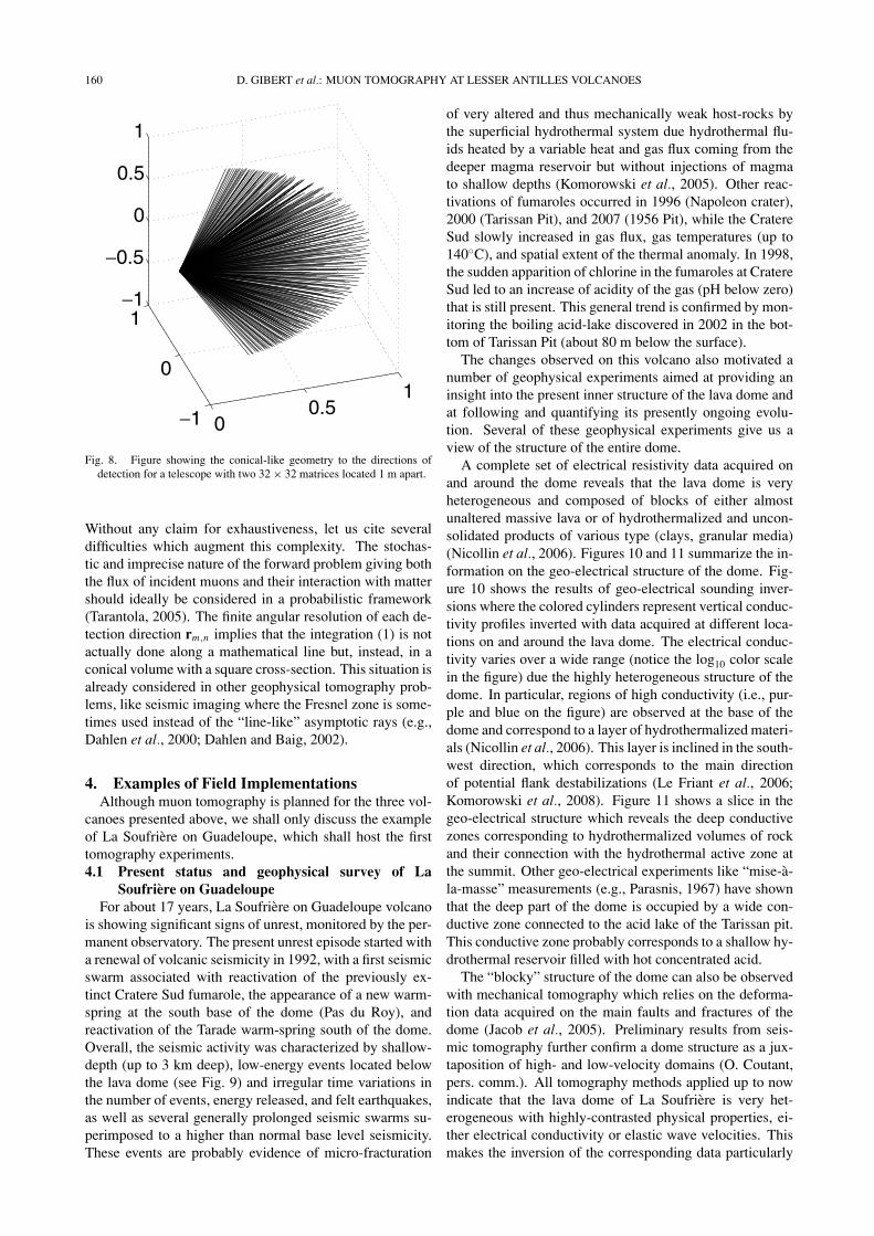
Because of the point-like geometry of the telescopes rela-tive to the size of a volcano, the integration paths Rν are notparallel lines but instead have a conical geometry, as shownin Fig. 8. The resulting conical tomography may be madeequivalent to the parallel tomography described above andinvolves the first derivative of the Radon transform of theobject (Grangeat, 1991). For this, the data set must satisfythe Tuy condition (Tuy, 1983). Note that this condition isnot satisfied if the acquisition point (i.e., the telescope) de-scribes a full circle around the volcano.
Neither the Orlov nor the Tuy conditions can be satis-fied for measurements performed on a volcano, and the to-mography reconstruction will practically be performed witha hugely incomplete data set. This makes the inverse to-mography problem very ill-posed with a non-uniquenessof the solution and eventually fully unresolved parameters(Tarantola, 2005). The inverse problem may be made moretractable by using additional information provided eitherby other geophysical tomography models (electrical, seis-mic, mechanical) or by prior geological data. Also, the to-mography inversion can be made more stable by carefullychoosing the parametrization of the model, i.e., the way bywhich the density distribution ρ is mathematically repre-sented (e.g., Tarantola and Nercessian, 1984).
The particular points mentioned above reveal the compli-cated nature of the inverse problem in muon tomography.
160 D. GIBERT et al.: MUON TOMOGRAPHY AT LESSER ANTILLES VOLCANOES
Fig. 8. Figure showing the conical-like geometry to the directions ofdetection for a telescope with two 32 × 32 matrices located 1 m apart.
Without any claim for exhaustiveness, let us cite severaldifficulties which augment this complexity. The stochas-tic and imprecise nature of the forward problem giving boththe flux of incident muons and their interaction with mattershould ideally be considered in a probabilistic framework(Tarantola, 2005). The finite angular resolution of each de-tection direction rm,n implies that the integration (1) is notactually done along a mathematical line but, instead, in aconical volume with a square cross-section. This situation isalready considered in other geophysical tomography prob-lems, like seismic imaging where the Fresnel zone is some-times used instead of the “line-like” asymptotic rays (e.g.,Dahlen et al., 2000; Dahlen and Baig, 2002).
4. Examples of Field ImplementationsAlthough muon tomography is planned for the three vol-
canoes presented above, we shall only discuss the exampleof La Soufriere on Guadeloupe, which shall host the firsttomography experiments.4.1 Present status and geophysical survey of La
Soufriere on GuadeloupeFor about 17 years, La Soufriere on Guadeloupe volcano
is showing significant signs of unrest, monitored by the per-manent observatory. The present unrest episode started witha renewal of volcanic seismicity in 1992, with a first seismicswarm associated with reactivation of the previously ex-tinct Cratere Sud fumarole, the appearance of a new warm-spring at the south base of the dome (Pas du Roy), andreactivation of the Tarade warm-spring south of the dome.Overall, the seismic activity was characterized by shallow-depth (up to 3 km deep), low-energy events located belowthe lava dome (see Fig. 9) and irregular time variations inthe number of events, energy released, and felt earthquakes,as well as several generally prolonged seismic swarms su-perimposed to a higher than normal base level seismicity.These events are probably evidence of micro-fracturation
of very altered and thus mechanically weak host-rocks bythe superficial hydrothermal system due hydrothermal flu-ids heated by a variable heat and gas flux coming from thedeeper magma reservoir but without injections of magmato shallow depths (Komorowski et al., 2005). Other reac-tivations of fumaroles occurred in 1996 (Napoleon crater),2000 (Tarissan Pit), and 2007 (1956 Pit), while the CratereSud slowly increased in gas flux, gas temperatures (up to140◦C), and spatial extent of the thermal anomaly. In 1998,the sudden apparition of chlorine in the fumaroles at CratereSud led to an increase of acidity of the gas (pH below zero)that is still present. This general trend is confirmed by mon-itoring the boiling acid-lake discovered in 2002 in the bot-tom of Tarissan Pit (about 80 m below the surface).
The changes observed on this volcano also motivated anumber of geophysical experiments aimed at providing aninsight into the present inner structure of the lava dome andat following and quantifying its presently ongoing evolu-tion. Several of these geophysical experiments give us aview of the structure of the entire dome.
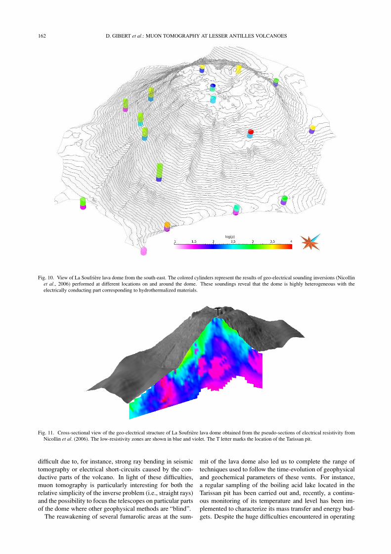
A complete set of electrical resistivity data acquired onand around the dome reveals that the lava dome is veryheterogeneous and composed of blocks of either almostunaltered massive lava or of hydrothermalized and uncon-solidated products of various type (clays, granular media)(Nicollin et al., 2006). Figures 10 and 11 summarize the in-formation on the geo-electrical structure of the dome. Fig-ure 10 shows the results of geo-electrical sounding inver-sions where the colored cylinders represent vertical conduc-tivity profiles inverted with data acquired at different loca-tions on and around the lava dome. The electrical conduc-tivity varies over a wide range (notice the log10 color scalein the figure) due the highly heterogeneous structure of thedome. In particular, regions of high conductivity (i.e., pur-ple and blue on the figure) are observed at the base of thedome and correspond to a layer of hydrothermalized materi-als (Nicollin et al., 2006). This layer is inclined in the south-west direction, which corresponds to the main directionof potential flank destabilizations (Le Friant et al., 2006;Komorowski et al., 2008). Figure 11 shows a slice in thegeo-electrical structure which reveals the deep conductivezones corresponding to hydrothermalized volumes of rockand their connection with the hydrothermal active zone atthe summit. Other geo-electrical experiments like “mise-a-la-masse” measurements (e.g., Parasnis, 1967) have shownthat the deep part of the dome is occupied by a wide con-ductive zone connected to the acid lake of the Tarissan pit.This conductive zone probably corresponds to a shallow hy-drothermal reservoir filled with hot concentrated acid.
The “blocky” structure of the dome can also be observedwith mechanical tomography which relies on the deforma-tion data acquired on the main faults and fractures of thedome (Jacob et al., 2005). Preliminary results from seis-mic tomography further confirm a dome structure as a jux-taposition of high- and low-velocity domains (O. Coutant,pers. comm.). All tomography methods applied up to nowindicate that the lava dome of La Soufriere is very het-erogeneous with highly-contrasted physical properties, ei-ther electrical conductivity or elastic wave velocities. Thismakes the inversion of the corresponding data particularly

D. GIBERT et al.: MUON TOMOGRAPHY AT LESSER ANTILLES VOLCANOES 161
Fig. 9. Volcanic seismic events recorded at Soufriere (Guadeloupe) from 2001 to 2008. Symbols stand for hypocenter locations, size for magnitudes,gray tunes for depth (see inset legend for details). A star around a symbol means a felt event. Circles are volcano-tectonic type events, diamonds arelong-period events (no magnitude available). Thick black lines represent main geological structures: regional faults and caldera rims (after Feuilletet al., 2002). Triangles indicate permanent seismic stations. Data and plot modi ed from OVSG-IPGP WebObs monitoring system (Beauducel et al.,2004).
162 D. GIBERT et al.: MUON TOMOGRAPHY AT LESSER ANTILLES VOLCANOES
Fig. 10. View of La Soufriere lava dome from the south-east. The colored cylinders represent the results of geo-electrical sounding inversions (Nicollinet al., 2006) performed at different locations on and around the dome. These soundings reveal that the dome is highly heterogeneous with theelectrically conducting part corresponding to hydrothermalized materials.
Fig. 11. Cross-sectional view of the geo-electrical structure of La Soufriere lava dome obtained from the pseudo-sections of electrical resistivity fromNicollin et al. (2006). The low-resistivity zones are shown in blue and violet. The T letter marks the location of the Tarissan pit.
difficult due to, for instance, strong ray bending in seismictomography or electrical short-circuits caused by the con-ductive parts of the volcano. In light of these difficulties,muon tomography is particularly interesting for both therelative simplicity of the inverse problem (i.e., straight rays)and the possibility to focus the telescopes on particular partsof the dome where other geophysical methods are “blind”.
The reawakening of several fumarolic areas at the sum-
mit of the lava dome also led us to complete the range oftechniques used to follow the time-evolution of geophysicaland geochemical parameters of these vents. For instance,a regular sampling of the boiling acid lake located in theTarissan pit has been carried out and, recently, a continu-ous monitoring of its temperature and level has been im-plemented to characterize its mass transfer and energy bud-gets. Despite the huge difficulties encountered in operating

D. GIBERT et al.: MUON TOMOGRAPHY AT LESSER ANTILLES VOLCANOES 163
Fig. 12. Top: Time evolution of the temperature in the acid lake of the Tarissan pit. Observe the transient increases of temperature which may be dueto fluctuations of the gas flux. Bottom: Time evolution of the pH in the boiling lake in the Tarissan pit. Observe the step-like nature of the evolutioncurve, which may be produced by gas release in the magma chamber.
0
200
400
600
800
1000
1200
0
500
1000
1500
1100
1150
1200
1250
1300
1350
1400
1450
1500
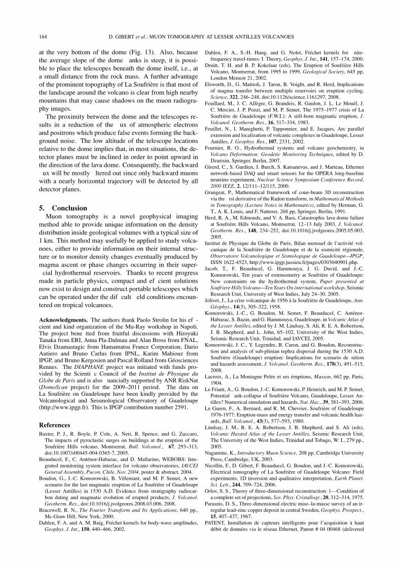
Fig. 13. Simulation of a muon radiography experiment on La Soufriere on Guadeloupe performed with a telescope equipped with two 16 × 16 matriceslocated 1 m apart. The point marks the location of the telescope, and the straight black lines represent the discrete lines of sight of the detectionsystem.
these equipments, the data collected up to now clearly showabrupt changes in the physical (Fig. 12 top) and chemical(Fig. 12 bottom) parameters of the shallow hydrothermalsystem. The causes of the observed changes remain puz-zling and may involve a release of both thermal energy andmagmatic gases after the fracturing of the plastic envelopesurrounding the magma chamber (Fournier, 2007). Alterna-tively, the opening of channels enabling new exchanges be-tween up-to-now separated hydrothermal reservoirs mightalso explain the abrupt changes observed. In either case, aprecise knowledge of the structure of the lava dome is desir-
able to help to “deconvolve” the signals emitted by the deephydrothermal system from shallow effects like channeling,mixing, etc.
For a detailed account of the evolution of the chemicalparameters, the reader is referred to the monthly reportsof the Volcanological Observatory on the web site of theInstitut de Physique du Globe de Paris.4.2 Muon tomography of La Soufriere on Guadeloupe
The prominent situation of the lava dome of La Soufriere(Fig. 2(E)) is particularly convenient for muon tomography,and several places exist where the telescopes can be placed
164 D. GIBERT et al.: MUON TOMOGRAPHY AT LESSER ANTILLES VOLCANOES
at the very bottom of the dome (Fig. 13). Also, becausethe average slope of the dome anks is steep, it is possi-ble to place the telescopes beneath the dome itself, i.e., ata small distance from the rock mass. A further advantageof the prominent topography of La Soufriere is that most ofthe landscape around the volcano is clear from high nearbymountains that may cause shadows on the muon radiogra-phy images.
The proximity between the dome and the telescopes re-sults in a reduction of the ux of atmospheric electronsand positrons which produce false events forming the back-ground noise. The low altitude of the telescope locationsrelative to the dome implies that, in most situations, the de-tector planes must be inclined in order to point upward inthe direction of the lava dome. Consequently, the backward
ux will be mostly ltered out since only backward muonswith a nearly horizontal trajectory will be detected by alldetector planes.
5. ConclusionMuon tomography is a novel geophysical imaging
method able to provide unique information on the densitydistribution inside geological volumes with a typical size of1 km. This method may usefully be applied to study volca-noes, either to provide information on their internal struc-ture or to monitor density changes eventually produced bymagma ascent or phase changes occurring in their super-
cial hydrothermal reservoirs. Thanks to recent progressmade in particle physics, compact and ef cient solutionsnow exist to design and construct portable telescopes whichcan be operated under the dif cult eld conditions encoun-tered on tropical volcanoes.
Acknowledgments. The authors thank Paolo Strolin for his ef -cient and kind organization of the Mu-Ray workshop in Napoli.The project bene tted from fruitful discussions with HiroyukiTanaka from ERI, Anna Pla-Dalmau and Alan Bross from FNAL,Elvis Dzamastagic from Hamamatsu France Corporation, DarioAutiero and Bruno Carlus from IPNL, Karim Mahiouz fromIPGP, and Bruno Kergosien and Pascal Rolland from GeosciencesRennes. The DIAPHANE project was initiated with funds pro-vided by the Scienti c Council of the Institut de Physique duGlobe de Paris and is also nancially supported by ANR RiskNat(DomoScan project) for the 2009–2011 period. The data onLa Soufriere on Guadeloupe have been kindly provided by theVolcanological and Seismological Observatory of Guadeloupe(http://www.ipgp.fr). This is IPGP contribution number 2591.
ReferencesBaxter, P. J., R. Boyle, P. Cole, A. Neri, R. Spence, and G. Zuccaro,
The impacts of pyroclastic surges on buildings at the eruption of theSoufriere Hills volcano, Montserrat, Bull. Volcanol., 67, 293–313,doi:10.1007/s00445-004-0365-7, 2005.
Beauducel, F., C. Antenor-Habazac, and D. Mallarino, WEBOBS: Inte-grated monitoring system interface for volcano observatories, IAVCEIGeneral Assembly, Pucon, Chile, Nov. 2004, poster & abstract, 2004.
Boudon, G., J.-C. Komorowski, B. Villemant, and M. P. Semet, A newscenario for the last magmatic eruption of La Soufriere of Guadeloupe(Lesser Antilles) in 1530 A.D. Evidence from stratigraphy radiocar-bon dating and magmatic evolution of erupted products, J. Volcanol.Geotherm. Res., doi:10.1016/j.jvolgeores.2008.03.006, 2008.
Bracewell, R. N., The Fourier Transform and Its Applications, 640 pp.,Mc-Graw Hill, New York, 2000.
Dahlen, F. A. and A. M. Baig, Frechet kernels for body-wave amplitudes,Geophys. J. Int., 150, 440–466, 2002.
Dahlen, F. A., S.-H. Hung, and G. Nolet, Frechet kernels for nite-frequency travel-times: I. Theory, Geophys. J. Int., 141, 157–174, 2000.
Druitt, T. H. and B. P. Kokelaar (eds), The Eruption of Soufriere HillsVolcano, Montserrat, from 1995 to 1999, Geological Society, 645 pp,London Memoir 21, 2002.
Elsworth, D., G. Mattioli, J. Taron, B. Voight, and R. Herd, Implicationsof magma transfer between multiple reservoirs on eruption cycling,Science, 322, 246–248, doi:10.1126/science.1161297, 2008.
Feuillard, M., J. C. Allegre, G. Brandeis, R. Gaulon, J. L. Le Mouel, J.C. Mercier, J. P. Pozzi, and M. P. Semet, The 1975–1977 crisis of LaSoufriere de Guadeloupe (F.W.I.): A still-born magmatic eruption, J.Volcanol. Geotherm. Res., 16, 317–334, 1983.
Feuillet, N., I. Manighetti, P. Tapponnier, and E. Jacques, Arc parallelextension and localization of volcanic complexes in Guadeloupe, LesserAntilles, J. Geophys. Res., 107, 2331, 2002.
Fournier, R. O., Hydrothermal systems and volcano geochemistry, inVolcano Deformation: Geodetic Monitoring Techniques, edited by D.Dzurisin, Springer, Berlin, 2007.
Girerd, C., S. Gardien, J. Burch, S. Katsanevas, and J. Marteau, Ethernetnetwork-based DAQ and smart sensors for the OPERA long-baselineneutrino experiment, Nuclear Science Symposium Conference Record,2000 IEEE, 2, 12/111–12/115, 2000.
Grangeat, P., Mathematical framework of cone-beam 3D reconstructionvia the rst derivative of the Radon transform, in Mathematical Methodsin Tomography (Lecture Notes in Mathematics), edited by Herman, G.T., A. K. Louis, and F. Natterer, 268 pp, Springer, Berlin, 1991.
Herd, R. A., M. Edmonds, and V. A. Bass, Catastrophic lava dome failureat Soufriere Hills Volcano, Montserrat, 12–13 July 2003, J. Volcanol.Geotherm. Res., 148, 234–252, doi:10.1016/j.jvolgeores.2005.05.003,2005.
Institut de Physique du Globe de Paris, Bilan mensuel de l’activite vol-canique de la Soufriere de Guadeloupe et de la sismicite regionale,Observatoire Volcanologique et Sismologique de Guadeloupe—IPGP,ISSN 1622-4523, http://www.ipgp.jussieu.fr/pages/0303040901.php.
Jacob, T., F. Beauducel, G. Hammouya, J. G. David, and J.-C.Komorowski, Ten years of extensometry at Soufriere of Guadeloupe:New constraints on the hydrothermal system, Paper presented atSoufriere Hills Volcano—Ten Years On international workshop, SeismicResearch Unit, University of West Indies, July 24–30, 2005.
Jolivet, J., La crise volcanique de 1956 a la Soufriere de Guadeloupe, Ann.Geophys., 14(3), 305–322, 1958.
Komorowski, J.-C., G. Boudon, M. Semet, F. Beauducel, C. Antenor-Habazac, S. Bazin, and G. Hammouya, Guadeloupe, in Volcanic Atlas ofthe Lesser Antilles, edited by J. M. Lindsay, S. Ali, R. E. A. Robertson,J. B. Shepherd, and L. John, 65–102, University of the West Indies,Seismic Research Unit, Trinidad, and IAVCEI, 2005.
Komorowski, J. C., Y. Legendre, B. Caron, and G. Boudon, Reconstruc-tion and analysis of sub-plinian tephra dispersal during the 1530 A.D.Soufriere (Guadeloupe) eruption: Implications for scenario de nitionand hazards assessment, J. Volcanol. Geotherm. Res., 178(3), 491–515,2008.
Lacroix, A., La Montagne Pelee et ses eruptions, Masson, 662 pp, Paris,1904.
Le Friant, A., G. Boudon, J.-C. Komorowski, P. Heinrich, and M. P. Semet,Potential ank-collapse of Soufriere Volcano, Guadeloupe, Lesser An-tilles? Numerical simulation and hazards, Nat. Haz., 39, 381–393, 2006.
Le Guern, F., A. Bernard, and R. M. Chevrier, Soufriere of Guadeloupe1976-1977: Eruption-mass and energy transfer and volcanic health haz-ards, Bull. Volcanol., 43(3), 577–593, 1980.
Lindsay, J. M., R. E. A. Robertson, J. B. Shepherd, and S. Ali (eds),Volcanic Hazard Atlas of the Lesser Antilles, Seismic Research Unit,The University of the West Indies, Trinidad and Tobago, W. I., 279 pp.,2005.
Nagamine, K., Introductory Muon Science, 208 pp, Cambridge UniversityPress, Cambridge, UK, 2003.
Nicollin, F., D. Gibert, F. Beauducel, G. Boudon, and J.-C. Komorowski,Electrical tomography of La Soufriere of Guadeloupe Volcano: Fieldexperiments, 1D inversion and qualitative interpretation, Earth Planet.Sci. Lett., 244, 709–724, 2006.
Orlov, S. S., Theory of three-dimensional reconstruction: 1—Condition ofa complete set of projections, Sov. Phys. Cristallogr., 20, 312–314, 1975.
Parasnis, D. S., Three-dimensional electric mise–la-masse survey of an ir-regular lead-zinc copper deposit in central Sweden, Geophys. Prospect.,15, 407–437, 1967.
PATENT, Installation de capteurs intelligents pour l’acquisition a hautdebit de donnees via le reseau Ethernet, Patent # 04 00468 (delivered
D. GIBERT et al.: MUON TOMOGRAPHY AT LESSER ANTILLES VOLCANOES 165
with number # 06/16 dated 2006.04.21), 2006.Pla-Dalmau, A., A. D. Bross, and K. L. Mellott, Low-cost extruded plastic
scintillator, Nucl. Instr. Meth., A466, 482–491, 2001.Pla-Dalmau, A., A. D. Bross, and V. V. Rykalin, Extruding plastic scintil-
lator at Fermilab, FERMILAB-CONF-03-318, Proceedings of the 2003IEEE Nuclear Science Symposium and Medical Imaging Conference,Portland, Oregon, USA October 16–26, 2003.
Pla-Dalmau, A., A. D. Bross, V. V. Rykalin, and B. M. Wood, Extrudedplastic scintillator for MINERvA, FERMILAB-CONF-05-506, Pro-ceedings of the 2005 IEEE Nuclear Science Symposium and MedicalImaging Conference, Puerto Rico, October 23–29, 2005.
Romer, M., La derniere Eruption de la montagne Pelee, Bull. Volcanol.,3:4, 89–116, 1931.
Tanaka, H. K. M. and I. Yokoyama, Muon radiography and deforma-tion analysis of the lava dome formed by the 1944 eruption of Usu,Hokkaido—Contact between high-energy physics and volcano physics,Proc. Jpn. Acad., B84 107–116, 2008.
Tanaka, H., K. Nagamine, S. N. Nakamura, and K. Ishida, Radiographicmeasurements of the internal structure of Mt. West Iwate with near hor-izontal cosmic ray muons and future developments, Nucl. Instr. Meth.Phys. Res., A555, 164–172, 2005.
Tanaka, H. K. M., T. Nakano, S. Takahashi, J. Yoshida, H. Ohshima,T. Maekawa, H. Watanabe, and K. Niwa, Imaging the conduitsize of the dome with cosmic ray muons: The structure beneathShowa Shinzan Lava Dome, Japan, Geophys. Res. Lett., 34, L22311,doi:10.1029/2007GL031389, 2007a.
Tanaka, H., T. Nakano, S. Takahashi, J. Yoshida, M. Takeo, J. Oikawa, T.Ohminato, Y. Aoki, E. Koyama, H. Tsuji, and K. Niwa, High resolutionimaging in the inhomogeneous crust with cosmic ray muon radiography:The density structure below the volcanic crater oor of Mt. Asama,Japan, Earth Planet. Sci. Lett., 263, 104–113, 2007b.
Tanaka, H. K. M., T. Nakano, S. Takahashi, J. Yoshida, and K. Niwa, De-velopment of an emulsion imaging system for cosmic-ray muon radio-graphy to explore the internal structure of a volcano, Mt. Asama, Nucl.Instr. Meth. Phys. Res., A575, 489–497, 2007c.
Tanaka, H. K. M., T. Nakano, S. Takahashi, J. Yoshida, M. Takeo, J.Oikawa, T. Ohminato, Y. Aoki, E. Koyama, H. Tsuji, H. Ohshima, T.Maekawa, H. Watanabe, and K. Niwa, Radiographic imaging below avolcanic crater oor with cosmic-ray muons, Am. J. Sci., 308, 843–850,2008.
Tarantola, A., Inverse Problem Theory and Methods for Model ParameterEstimation, 342 pp., Society for Industrial and Applied Mathematics,Philadelphia, 2005.
Tarantola, A. and A. Nercessian, Three-dimensional inversion withoutblocks, Geophys. J. R. Astron. Soc., 76, 299–306, 1984.
Tuy, H. H., An inversion formula for cone-beam reconstruction, SIAM J.Appl. Math., 43, 546–552, 1983.
Villemant, B., G. Hammouya, A. Michel, M. P. Semet, J.-C. Komorowski,G. Boudon, and J.-L. Cheminee, The memory of volcanic waters:shallow magma degassing revealed by halogen monitoring in thermalsprings of La Soufriere volcano (Guadeloupe, Lesser Antilles), EarthPlanet. Sci. Lett., 237, 710–728, 2005.
Wadge, G., D. G. Macfarlane, H. M. Odbert, M. R. James, J. K. Hole, G.Ryan, V. Bass, S. De Angelis, H. Pinkerton, D. A. Robertson, and S.C. Loughlin, Lava dome growth and mass wasting measured by a timeseries of ground-based radar and seismicity observations, J. Geophys.Res., 113, doi:10.1029/2007JB005466, 2008.
D. Gibert (e-mail: [email protected]), F. Beauducel, Y. Declais, N.Lesparre, J. Marteau, F. Nicollin, and A. Tarantola