mw-200 series - flowserve · installation . instructions. durametallic ® mw-200 series. liquid...
TRANSCRIPT
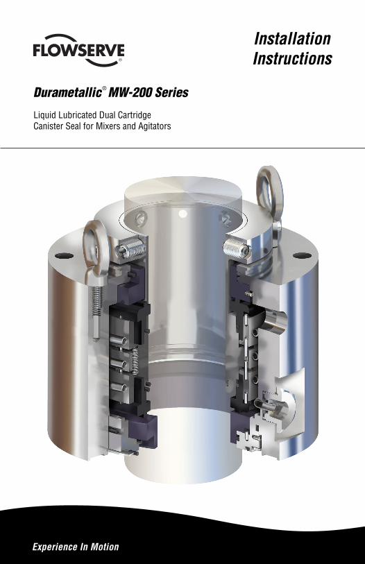
Installation Instructions
Durametallic® MW-200 Series
Liquid Lubricated Dual CartridgeCanister Seal for Mixers and Agitators
Experience In Motion
2
1 Equipment Check1.1 Follow plant safety regulations prior to equipment disassembly:
• Consult the plant Material Safety Data Sheet (MSDS) files for hazardous material regulation. • Wear designated personal safety equipment. • Lock out the mixer or agitator motor and valves to and from the vessel. • Relieve any pressure in the vessel. • Use plant vessel entry procedures if it is necessary to enter the vessel.
1.2 Secure the mixer or agitator shaft in accordance with the mixer or agitator manufacturer’s instructions.
1.3 Remove the coupling and/or drive to access the seal area. Follow the manufacturer’s instructions.
1.4 Remove the existing seal assembly.1.5 Remove all burrs and sharp edges from the shaft and vessel
flange area. The shaft and vessel flange must be free of burrs, sharp edges, cuts, dents, or corrosion that might cause leakage past the sleeve packing O-rings and the gland gasket O-ring.
1.6 Check requirements for the shaft and the vessel flange. They must agree with the dimensions shown in Figure 1.
1.7 Check the assembly drawing accompanying the seal assembly for specific seal design data, materials of construction, dimensions, and recommended piping connections.
1.8 Check the shaft OD, vessel flange bolt size, bolt circle, and distance to the coupling or drive to ensure that these dimensions agree with the seal assembly drawing provided.
1.9 Handle the seal assembly with care, it is manufactured to precise tolerances. The sealing faces of the rotating face and the stationary faces are of special importance. These sealing faces are lapped to rigid specifications required for liquid lubricated seals. If it becomes necessary to disassemble the seal, keep these sealing faces clean and dry at all times and protect them from damage since they are subject to impact fracture.
The images of parts shown in these instructions may differ visually from the actual parts due to manufacturing processes that do not affect the part function or quality.
3
1.10 Pressure testing of this cartridge canister dual seal prior to installation is possible using filtered dry nitrogen or instrument air. Consult Flowserve, Flow Solutions for acceptable gas leakage rates for this seal design.
Caution: Bench test pressure is 3.5 bar (50 psi) maximum.
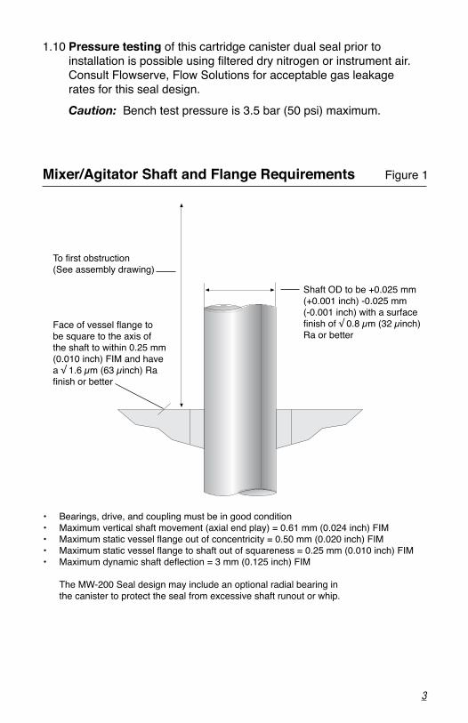
Mixer/Agitator Shaft and Flange Requirements Figure 1
To first obstruction(See assembly drawing)
Face of vessel flange to be square to the axis of the shaft to within 0.25 mm (0.010 inch) FIM and have a √ 1.6 µm (63 µinch) Ra finish or better
Shaft OD to be +0.025 mm (+0.001 inch) -0.025 mm (-0.001 inch) with a surface finish of √ 0.8 µm (32 µinch) Ra or better
• Bearings, drive, and coupling must be in good condition• Maximum vertical shaft movement (axial end play) = 0.61 mm (0.024 inch) FIM• Maximum static vessel flange out of concentricity = 0.50 mm (0.020 inch) FIM• Maximum static vessel flange to shaft out of squareness = 0.25 mm (0.010 inch) FIM• Maximum dynamic shaft deflection = 3 mm (0.125 inch) FIM
The MW-200 Seal design may include an optional radial bearing in the canister to protect the seal from excessive shaft runout or whip.
4
2 MW-200 Seal InstallationTools needed:
Tools provided: • Lubricant for O-rings and equipment shaft OD.
Tools not provided: • Wrenches to secure housing nuts or bolts • Allen wrenches for housing cap screws • Allen wrenches for setting devices and set screws
2.1 Install the seal adapter plate on the vessel flange if required.
2.2 Lightly lubricate the equipment shaft along the entire length the gasket O-rings will contact the shaft. Use the lubricant provided if it is compatible with the process fluid.
2.3 Secure the vessel flange O-ring in the gasket O-ring groove using the lubricant provided if it is compatible with the process fluid.
2.4 Install the MW-200 seal onto the equipment shaft with the end containing the setting devices toward the equipment drive end and position the seal assembly onto the vessel flange. Use the lifting eyes supplied to gently lower the canister assembly onto the adapter plate. Do not bolt the canister seal assembly to the adapter plate or vessel flange at this time. Care should be exercised when passing the seal sleeve incorporating the sleeve packing O-rings over any keyways or threads that may be present. Any steps or shoulders on the equipment shaft should be beveled to prevent damage (pinching and cutting) of these sleeve gasket O-rings during installation.
2.5 Position the canister seal assembly so that the liquid barrier ports and any optional bearing lubrication fittings are easily accessible.
5
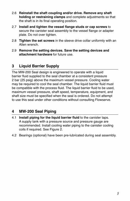
2.6 Reinstall the shaft coupling and/or drive. Remove any shaft holding or restraining clamps and complete adjustments so that the shaft is in its final operating position.
2.7 Install and tighten the vessel flange studs or cap screws to secure the canister seal assembly to the vessel flange or adapter plate. Do not over tighten.
2.8 Tighten the set screws in the sleeve drive collar uniformly with an Allen wrench.
2.9 Remove the setting devices. Save the setting devices and attachment hardware for future use.
3 Liquid Barrier SupplyThe MW-200 Seal design is engineered to operate with a liquid barrier fluid supplied to the seal chamber at a consistent pressure 2 bar (25 psig) above the maximum vessel pressure. Cooling water may be required to cool the seal chamber. The liquid barrier fluid must be compatible with the process fluid. The liquid barrier fluid to be used, maximum vessel pressure, shaft speed, temperature, equipment, and shaft size must be specified when the seal is ordered. Do not attempt to use this seal under other conditions without consulting Flowserve.
4 MW-200 Seal Piping4.1 Install piping for the liquid barrier fluid to the canister taps.
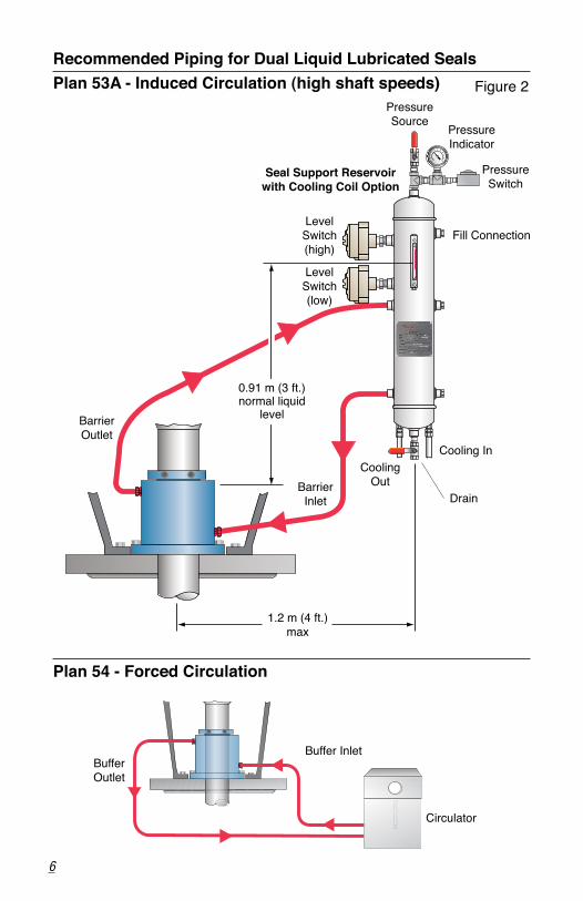
A supply tank with a pressure source and pressure gauge are recommended. Install cooling water piping to the canister cooling coils if required. See Figure 2.
4.2 Bearings (optional) have been pre-lubricated during seal assembly.
6
Recommended Piping for Dual Liquid Lubricated SealsPlan 53A - Induced Circulation (high shaft speeds) Figure 2
Plan 54 - Forced Circulation
BufferOutlet
Buffer Inlet
Circulator
1.2 m (4 ft.) max
Pressure Indicator
Pressure Source
PressureSwitch
Drain
Seal Support Reservoir with Cooling Coil Option
Level Switch (low)
Level Switch (high)
Cooling InCooling
Out
Fill Connection
BarrierInlet
BarrierOutlet
0.91 m (3 ft.)normal liquid
level
7
5 Seal OperationTo assure reliable operation of this sealing product, the following operating guidelines should be observed.
5.1 Maintain the liquid barrier fluid pressure both while the seal is operating and when the equipment is on standby.
5.2 Do not exceed the maximum barrier pressure specified for the seal design. The barrier pressure should be 2 bar (25 psig) above the operating vessel pressure.
5.3 Do not exceed the maximum vessel pressure specified for the application. This could reduce the recommended vessel to barrier differential pressure which could adversely affect seal performance.
5.4 Do not exceed the maximum vessel temperature specified for the application. This could exceed the temperature limits of the seal materials of construction applied to the application.
5.5 Do not exceed the seal material corrosion limits. This seal was designed for the application shown on the seal assembly drawing. Do not exceed the limits of the material alloys and elastomers supplied in its construction.
For any problems encountered during installation and/or operation of this product, contact your nearest Flowserve Sales and Service Representative or Authorized Distributor.
6 RepairThis product is a precision sealing device. The design and dimension tolerances are critical to seal performance. Only parts supplied by Flowserve should be used to repair a seal. To order replacement parts, refer to the part code and B/M number. A spare backup seal should be stocked to reduce repair time.
When seals are returned to Flowserve for repair, decontaminate the seal assembly and include an order marked "Repair or Replace." A signed certificate of decontamination must be attached. A Material Safety Data Sheet (MSDS) must be enclosed for any product that came in contact with the seal. The seal assembly will be inspected and, if repairable, it will be rebuilt, tested, and returned.
flowserve.com
TO REORDER REFER TOB/M #F.O.
To find your local Flowserve representativeand find out more about Flowserve Corporation, visit www.flowserve.com
FIS102eng REV 05/13 Printed in USA
Flowserve Corporation has established industry leadership in the design and manufacture of its products. When properly selected, this Flowserve product is designed to perform its intended function safely during its useful life. However, the purchaser or user of Flowserve products should be aware that Flowserve products might be used in numerous applications under a wide variety of industrial service conditions. Although Flowserve can provide general guidelines, it cannot provide specific data and warnings for all possible applications. The purchaser/user must therefore assume the ultimate responsibility for the proper sizing and selection, installation, operation, and maintenance of Flowserve products. The purchaser/user should read and understand the Installation Instructions included with the product, and train its employees and contractors in the safe use of Flowserve products in connection with the specific application.
While the information and specifications contained in this literature are believed to be accurate, they are supplied for informative purposes only and should not be considered certified or as a guarantee of satisfactory results by reliance thereon. Nothing contained herein is to be construed as a warranty or guarantee, express or implied, regarding any matter with respect to this product. Because Flowserve is continually improving and upgrading its product design, the specifications, dimensions and information contained herein are subject to change without notice. Should any question arise concerning these provisions, the purchaser/user should contact Flowserve Corporation at any one of its worldwide operations or offices.
© 2013 Flowserve Corporation
USA and Canada
Kalamazoo, Michigan USA
Telephone: 1 269 381 2650
Telefax: 1 269 382 8726
Europe, Middle East, Africa
Dortmund, Germany
Telephone: 49 231 69640
Telefax: 49 231 6964 248
Asia Pacific
Singapore
Telephone: 65 6544 6800
Telefax: 65 6214 0541
Latin America
Mexico City
Telephone: 52 55 5567 7170
Telefax: 52 55 5567 4224