mw - nasa · - mw the calculation of spau load distributions ... the siope of 'the lift curve...
TRANSCRIPT
TECHNICAL NOTES
NATIONAL ADVISORY COMMITTEE FOR AERONAUTICS
No. 834
- MW
THE CALCULATION OF SPAU LOAD DISTRIBUTIONS
ON SWEPT-BACK WINGS
By William iiutterDerl Langley Memorial Aeronautical Laboratory
4
Washington December 1941
https://ntrs.nasa.gov/search.jsp?R=19930081578 2019-02-02T06:21:00+00:00Z
ITATIO.ITAL ADVISORY COHMITTEE TOR AER0:1IAUTICS
TECHTTICAL IOTE iTO. 834
THE CALCULATIOIT OF SPA_- LOAD DISTRIPUTIO1TS
'.IT
By William Hutterperl
SUMIL'.P. Y
Span loa0_ distributions of swept-back. wings have been calculated.. The method used was to replace the wing with a bound. vortex at the civarter-chord. line and to calculate the (low-awash due to the system of bound and trailing vor-tices to conform at the three-Quarter-chorJ_ line to the slope 'of the flat-plate wing surface. Results are given for constant-chord and. 5:1 ta p erea plan forms, for sweep-back angles of 0°, 3Q0 and. 450, and for aspect ratios of 3, 6, and 9. Some comments on the stalling of swept-back wings are included.
TTr2RODUCTI CIT
AirTlano dosins are often proposed in which stability and. control are provd.od. by a wing with a large angle of swecp'oack instead of by the conventional fuselage and tail arrangement. The calculation of the aorodynauic forces is more difficult on such a wing than on the corresponding unswep t-. back wing because of the more comp licateft nature of the vortex system, the flow of which is to be calculated.. Tue problem is essentially that of two yawed. airfoils (the two halves of the swemt-back wing) subject not only to the effects of finite as'ect ratio but also to their mutual interference.
Hiegharcit has shown in his work with rectanular flat plat ' s (reference 1) that gooa accuracy in the total lift i orce can be attained b y reDlacing the plate with a bound vortex at the quarter-chore line nd making the d.ownwash due to the boun-, vortex nmd. its associated trailing vortex system conf dorm, at the three-quarter-chor line, to the slope of the flat plate.
OH SWEPT-BACK
Such a procedure is rigorously correct for an unyawed.,
2 iTACA TechnicàJ. Note No.. 834
rectangular flat p late of Infinite span. The method also hold.s for a yawed., infinite-span flat plate because, in this case, the spanwi se component of the free-stream ve-locity has no effect (if. potential flow is assu;ied.) on the lift whereas the component normal to the span has the same effect as on an un rawecl. airfoil. More precisely, lot the airfoil be yawed. through an angle A at zero angle of at-tad: and then rotated through an angle a. about the line with res pect to which A was measured.. If the free-stream velocity 11 is resolved. along the three mutually perpen-clicular directins - namely, spanwisp, chordwise erpendic-ular to the span, and normal to the plane of the flat plate - the velocity comp onents are, respectively, V sin.A cos a,, V cos A cos a,, and V sinct. Inasmuch as the chord measured normal to the span is c o cos A, then from two-dimensional thin-airfoil theory-, the circulation F is given by
F ii Vc 0 cos Asina. (i)
Also, from two-d.imenional wing theory, the canter of pressure of the lift forces is at the quarter-chord line. If a bound vortex of circulation given' by equation (i) is placed at the quarter-chord line, the normal induced veloc-ity w at the three-quarter-chord line is
Fi-rVc 0 cos A sin ct w = = -_____
2irr 2 CO Tr - cos A
or
w = V sin a.
(2)
which is exactly the amount.needed to . 'produce a resultant flow along the flat-plate equivalent of the thin airfoil at the three-quarter-chord point.
The extension of Wieghardt's method to flat plates of swept-back plan form has been made in the, present paper. A swept-back bound vortex was placed at the quarter-chord:. line (fig. 1) and the downwash due to the bound vortex and its trailing-vort-e-x sys , p was calculated at points on the three-quarter-chord. lLie. -The bound vortex strength was determined by the condition that the resultant flow at the three-quarter-chord line be tangent to the flat plate. The span loa-2 distribution thusdetermined shouldbë ex-pected to be less valid near the tips and the center of the
TACA.Tëchnical NoteNo...834 3
wing tI-.n in between. In the center, the, effect of one wing upon the other is strong and the bound órticos are curved lines rather than broi':on lines; whoreas, at the ti p s, the presence of strong trailing vortices invalidtesthc argu nent of the previous paragraphs, which was based on two-dimensional wing. thoorr
• The results obtainthd. for the f1atrl'ate wing surfaces Ti-.y be applied, to wings having the usual type of airfoil section on the assumption that 'the finite thickness and camber of the wing do not appreciably displace the vortex system from the hon zontal plane. Furthermore, inasmuch as the section lift-curve slope a 0 generally differs from 2rr, the airfoil c-hord to be used with the results of this paDer is
a0 c = -ccta1
This correction is based on the •two-d.inonsj onal. airfoil re-lation
-
r = - ca0Va.'.
in which ca 0 occurs as a'procluct. ' The value of a 0 will depend on the angle of swee ack A as well as on the air-foil section. If there were no viscosity 'effects nor trailing-vortex systo:i, a 0 would: be determined by the section per p endicular to thd span because the comp onent of the air flow perpendicular to 'the span produces the lift. The chief cause of 'the reduction in a 0 from its theoret-ical value as given by potential theory is, however, the viscosity phenomena (boundary layer, s'eparat'ion, etc.) that depend on the, actual path of the air particles over the airfoil. Because, for large aspect ratio at least, the streamlines over the airfoil do not greatly depart from the free-stream direction, the siope of 'the lift curve of the airfoil section in the free-stream direction should be used
SYLIBOLS
The * following symbols ', are used: ''
4 NACA Technical Note No • 834
b wing span, measured along quarter-chord line from tip to tip
S wing semispan (b/2)
A sweepback angle, measured. from q uartorchord line
a. angle of attack, measured in free stream direction.
S. area of lan' form of wing
C wing. chord tiOaired in froe-streati:d.irection
C 0 wing root chord measured in frco-strean direction
aspect ratio
--- L total lift
a 0 sloDo of section lift curve
C_ lift coefficient (L
) S
1. lift per unit leigth along sDan
F circulation
induced drag/D1
40 - induced-drag coefficient ( Di \. 2 2P
p density of. air
V free-stream air velocity.
W induced downwash. velocity
Coordinates:
TI coordinate of down-,rash point in direction of quarter-chord line (positive to right)
0 coordinate of bound vortox.eloraent in direction of quarter-chord line (positive to right)
center of pressure of span load distribution
NACA Technical Note No834 5
• angle corresponding. to.. :0 . ( Cos 0 =
ii angle corresponding to Tj (cos * = fl/..)
y perpendicular to free-stream direction in plane of • wing ( p ositive to right).
Subscripts:
+ refers to right side ..f wing -
refers to left side of wing
1 refers to bound vortex
2 refers to trailing vortex
LETHOD
The fiatpl.ae wing surface of swept-. ack plan form is replaced with a bound, vortex at the auarter-chord, line (fig. 1). The 'bound vortex and an element of the trailing-
as the sr.inbo1s use.• in the . following expressions,.. are : shown in figure 1 . . By the.BiotSavt law the-inducedve .loc .ity w (positive downward) at:..the point P on the three-quartC'r-chord line, duo to the bound vortex F on the ivarter-chord line, is
0.
Wi = 1. r sin •
(3)
which, ipon subst_tution of trie geoietrical relations
- 1+ - B + tan A cos e+ sin e+ =r+ ()
+E tan B • cos 8 = - - sin e =
becomes
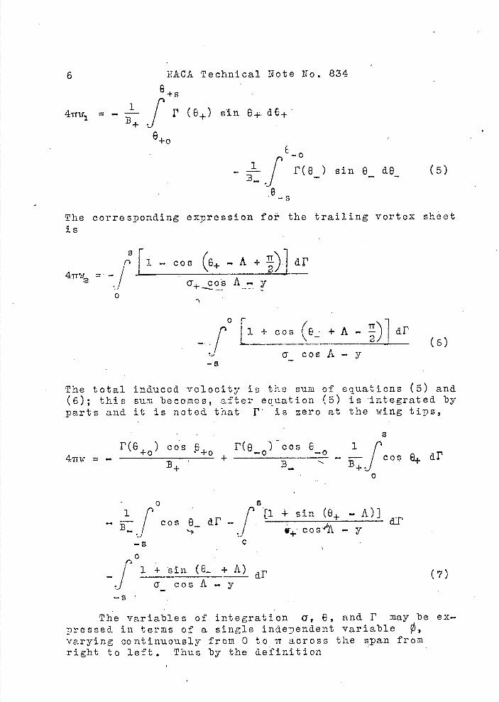
6 1ACA Technical Note No. 834
65
4w = — f r (e) n 6. dC+
6+0
fr(e) s in e d6 (5)
The corresponding expression foi the trailing vortex sheet is
4w
r[±_.. cos (e^ .. A +
cii
2J A. y 0
fL1^±)1 (6) o cosA—y
-s
The total induced velocity is the sum of equations (5) and (6); this sum becomes, after eauation (5) is integrated by parts and it is noted that 1' is zero at the wing tips,
4w = — 8^)
+ eoY: 6— 0
— cos8+ dr
0 8 1 rtl+ sin (e+—A)
— - I cos 6 d.F — i a__F
.1 cosA — y
0 p
— / 1 + sin (8. + A) dF (7) j crcosA—y
The variables of integration 0, 6, and F may be ex-pressed in terms of a single independent variable 0 9.
varying continuously from 0 to ir across the span from right to left. Thus by the definition
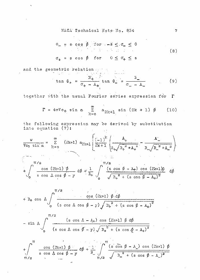
NAG Technical iTote III . 834 7
= s cos for ..- < a < 0
(e)
= s cos for 0 < cY^ < s
and. the geometric relation
tan 6 = tan 8' = (9)
together rith the usual Fourier séi'ies expression fr F
co
F = 4Tc 0 sin a E a, sin (2k + 1) 0 (10) 2 1=o 2y ,+l .
the following expression may be derived by substitution into equation (7):
W f, . \k/ A I \1 ) + =
Vc0(2k+l)
i=a +l L2
- - _______
1V+I/B+? +A B_JB_2 +A_2
TT /2 . TT /2 .
+ [ cos (21:+l)dØ
i[
(scos - cos (2k+l)pdØ
s cos.
A cos 0 - BI + (s co 0 -
11/2 • cos •(2k+i) 0 d
+B+ cos Aj . (s cos A cos 0 - )jBi + (5 cos - A+)2
11/2(s cos A - ) cos (2k+l) 0 —
J (s cos A cos Ø'- y) .JB+2 + (s cos ,o- - A+ )2
17 TT
+ [ cos (2h+1) r•(s_0 - A) cos (2k+1) 0 J s cos A cos - J
B- 2 + (s cos - A_)'
11 /2 ,/ 11/2 .•
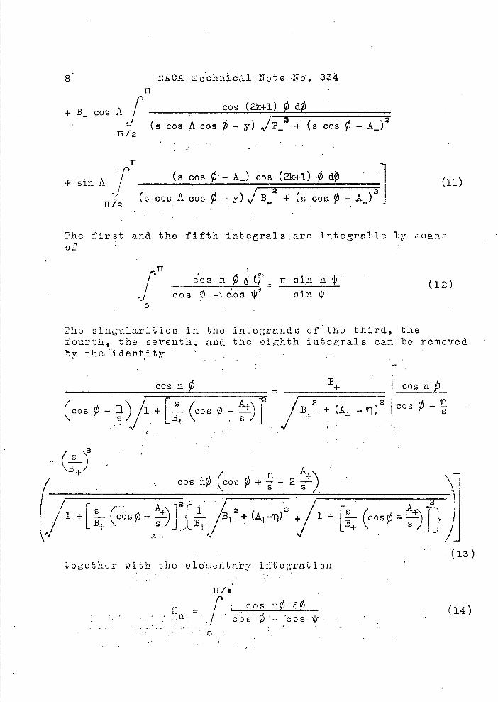
8 ITACA Techn.ca1 Note 'No'.. 83.4 TI
+ B
-
cos A f ' ____.
(+i) 0 ø
(s cos A cos 0 - y) 13a
+ (S cos 0 - A_)2 11/2
TT
+sin A(s cos 0- A_) cos-(2k+!) .0 dØ
(s .cos A cos 0 - y) J32 -
(s cos. 0 - A_ )2
The first and the fifth integrals are integrable by means of
IT-COS fl 0 (12)
jcos -' cbs '.ji sin 0
The singularities in the integrands of the third, the fourth, the seven
th, and the eighth intograls can be removed
by the identity
cos n0 = B+ cosn
Cos o L)/i+[ o ±) '/+H+ COS 0-
f\2 - -A
(
+ cosn0,(cos0^_2) -
+/i + [ (CoS)])
(13) together ith the 1o'moii.tay iiftogra'tion
11/
= r cos no ãØ (1) r J cosØ—cos1i
11/2
+!(i_ (A__)tan A)f cos (2i+i)d
(0^)G('5)
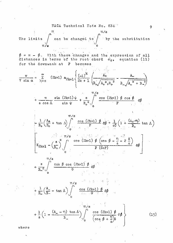
1TACA Technical Tote-No. 84.
TT
The limitsf can be changed by the substitution
1T/2 0
=TT- . with these changes an the expression of all distances in terms of the- root c-hord c', equation (ii) for the downwash at P becomes
WCD k /
(2k+l) a +l
2k
7A+ _V Sifl a. iro 2k + 1 B/ B_ iB+2 2 + 3_2)
Tr /a
Tr sin (2k+l)j + s / cos (2k-i-i) 0 cos 0 s cos A sin \IJ P
0
11/2
_(+ t )f cos (2k+i) dØ+ J(1 + tan A)an A
S f Cos
[K2k^1': -
—2 ) dOJ
11/2 +
cos 0 cos (2k.+1)
TT/2
cos+ A) tan (21,,+1)0dO
o
where
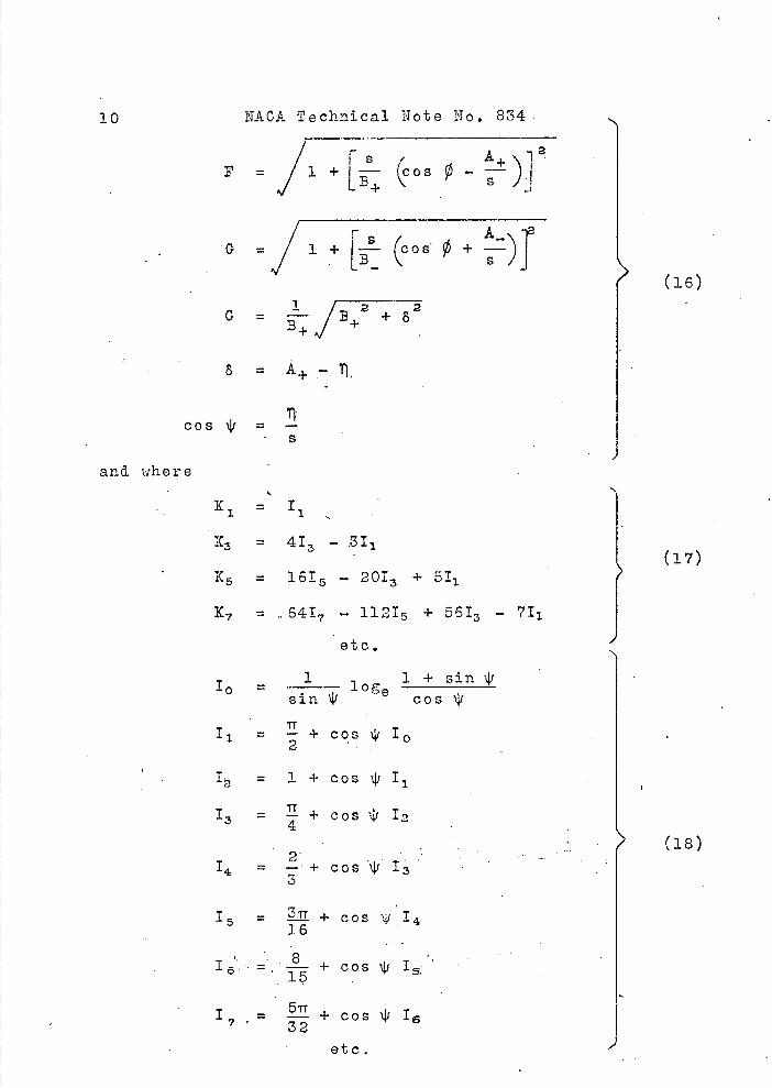
10 N&0A Technical Note No. 834
F =JTijcosø)i2
C = + 82
8 =
TI cos XV = - S
and where
K 1 = I
K3 = 413 - ,3I
K 5 = 16I - 201 3 + 5I
K 7 = 6417 - 1121 5 + 5613 - 71
(16)
(17)
etc.
1 1+sin4i 10sin \IJ cos4/
I i = + cos 'I' Ia
I = 1+c0S4/11
1 3 = - + COS \J In
2 14 = —± Cos \iI3
1 5 IL + COS
+ Cos I_•
1 7 = + cos \IJ 16
etc.
(18)
NACA Technical Note No. 834 11
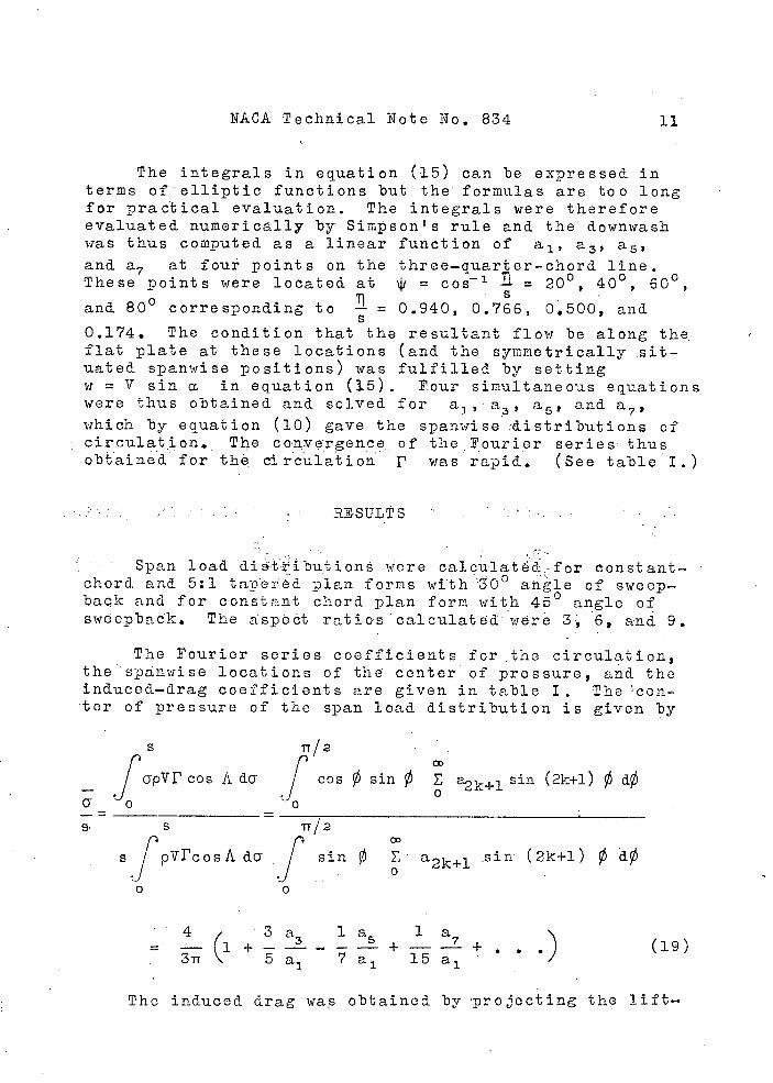
The integrals in equation (15) can be expressed in terms of elliptic functions but the formulas are too long for practical evaluation. The integrals were therefore evaluated numerically by Simpson's rule and the downwash was thus computed. as a linear function of a 1 , a 3 , a5, and a7 at four points on the three-quarter-chord line. These Doints were located at jj = cos-1 fl = 20 0 1 40°, 600,
and 80 0 corresponding to = 0.940, 0.766, 0500, and
0.174. The condition that the resultant flow be along the. flat plate at these locations (and the symmetrically it-uated spanwise positions) was fulfilled by setting w = V sin a. in equation (15). V.our simultaneous equations were thus obtained and solved for a 3 , a 3 , a 5 , and a,.,,, which by equation (10) gave the spanwise :d.istributions of circulation. The corzvergence. of :the Fourier series thus obtained for the circulation p was rapid. (See table I.)
RESULTS
Span load dietributions ifere calculated.-for constant-chord and 5:1 tao'eièd. Dian forms with 30° ahle of sweep-back and for constant chord plan form with 450 angle of sweepback. The aspOct ratios calcu1atd were 3, 6, and 9.
The Fourier series coefficients for the circulation, the spnwise locations of the center of pressure, and the induced-drag coefficients are given in table I. The cen ter of pressure of the span load distribution is given by
S 11/2
1apvr cos Ada cos/ 0 sin E a2k+l sin (2k+1) 0 dØ
OD
sfvrcosAda f sin 0 a2k+l sin (2k+l)
/ 43 a la la. .) (19)
311 5 5 a1 7 a 1 15 a1
The induced drag was obtained by projecting the lift-
12 NIA 0.1k T,echni'cal lio,te'iTo ... 834.
ing. ele-ment's -into one line perpendiculart. the free-stream direction (Nunk's stagger theorem,- reference . 2) and obtain-ing the induced drag of the resulting 1ifting-1ine distri-bution. Thus, for the distribution . . .
CO
F = 4i-r v c sin '..a E a2k+l sin (2+1) 0 regarded as a lifting-line, distribution, the induced drag is
s cos, A
D. = 2 'T . . _____ dy 1 .
j V cos 'A
11/2
' 2 22 CO
CO
=Stt PV c0
,[
(2k+l) a2k+l sin(2k+l)0 a2+1 sin(2n+l)Ø dØ
With the relation between CL and a 1 derived, in equation (21)
CDi1(2k + ) ( a 2k+ . ', '(20)
which holds for both the constant—chord and the tapered plan fortis.
The. total lift forces are obtained from a as fol-lows: .. .. . . .
Constant chord.: , L . p V cos A f r ds
CL = 2, 2112 a a1
pV S 'jpV S
5:1 taper; . . ' (21)
L 0L = ': 10 - 11 2 a. a
1 2 C 1 ' 3 1
—pV b.Q (1+-F-) cos A
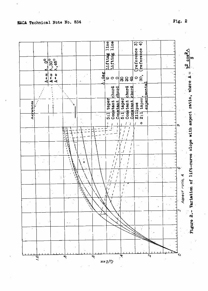
The variation of the total lift forces with as p ect ratio is given in figure 2. ''The àurve, .for' zero angle: of sweepback is ractical1y identical with that given by Wieghardt (ref-erence 1, fig. 4) but is extended to as aspect ratio of 9.
lull CL A A—>0 2-act -
(22a)
IIACA Technical Note' No.. 834 13
Included for comparison are the curves for the correspond.-. ing unswept-back plan forms obtained from lifting-line theory, a curve due to Krienes (reference 3) for an ellip-tical flat plate calculated on the basis of the accelera-tioñ potential, and a result from experimental work (ref-erence 4) for a 2:1 tapered wing of 300 sweepback. There is a surprisingly large difference between the total lift forces predicted by the ordinary- lifting-line theory and those predicted by the modified theory used in this report. The exp eriments of Winter (reference 5, fig. 36) on rectangular flat plates favor the modified theory.
For a low aspect ratio and. an arbitrary plan form, equation (24) for the limiting s pan load distribution (presented later in this paper) yields
while for large aspect ratio and arbitrary taper, equation (1) , gives .
urn CL,cosA
A—>co 2iTcL(22b)
The reduction of lift by cos A, indicated by the preced-ing expression, may be regarded. as a first approximation to the lower lift force of a swept-back wing. Figure 2 in-dicates that the approxiirati,on becomes loss valid for lower aspect ratios, higher angles of sweepback, and higher amounts of taper.
A comarison of: . the curves for the constant-chord, 30. and 45 sweepbaek plai forms; and the . r.e.ctanu1a-r plan form (by Wieghardt's method) shows that the ttal lift-cur.veslopes are reducea by about.7 . and 19 percent forhe 300 and the 450 cases, respectively, at an aspect ratio of 6. If the total lift of the rectangular plan formob-tamed by lifting-line theory is .. used as. a. basis of com-parison, the corros po n4i ng. . t o t a 1 lift reductions are 14 and 25-1 percent. ..
Figure 2 also shaws that the reduction in lift of the swept-back tapered. plan f .orn is much less than that of the swept - back constant-chord...plan form.
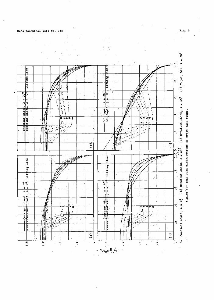
The span . load distributions. are shown in figure 3. The ordinates are given by
14 NACA Tehnica1 Note No. 834
r. (23) 2
TrV-c 0 cLa 1 -
.It--anb-e shown that as the aspect. ratio- approa Cho s.ze:ro, equation (ii) yields-,-- fo:r -an-arbitrary- p1n.form,
lire = sin- Ø (24) AO *PV S'CL TT
as a limiting form.
Figure ' 3 show.s that the wings with the swept-back constant-chord plan forms have higher tip loadings than the correspondin g unswopt-back wings. This result implies greater tip-stalling tendencies forswept-back wings. Furthermore, the root sections tend, with higher aspect ratios, to be less loaded than the sections halfway bo-tweeh root and. tip. That this result must be valid is evident from the fact that a yawed, infinite-as pect-ratio, constant-chord airfoil has a uniform span load distribution. If one-half of the airfoil is bent back to form a swept-back wing and if the bound vortex strength remains the same, points near the root section, which originally had the proper clownwash to conform to the slope of. the surface, would now have too much downwash; hence the bound vorticity must be reduced at and near the root section.
- Figure 3(a) indicates hat lifting-line theory pre-dicts higher tip loading than is -given by the modified theory used herein. Now, the trailing vortex system in-duces loss downwash tt the quarter-chord line than at the three-quartoi-chord line. Since lifting-line theory de-ducts the -downwash angle at the quarter-chord line from the geometric angle of attack, the lift near the tips therefore appeas higher than that given by the modified thoo ry. -
The. spanwise location of tho beginning of the stall on a swept-back wing and the corresponding angle of attack are, however, primarily dependent on the spanwise flow of- the boundary layer on the suction surface. This spanwise flow is due to the surface -pressure distribution.- On a swept-back wing the surface pressure gadiëñts sweep the slower moving air of' the boundary ler toward the - tip. Some tuft observations on constant-chord swept-back and swept-forward wingsindicated hat,. in addition,- . the tip
l.b
*p V2 SCL
NACA Technical- Note No. 834 15
vortex, which was coming off the top of the wing, provided an added local inducement for the boundary layer to sweep toward the tip. Near the tip, the thicker boundary layer (before it has been excessively influenced or removed by the favorable pressure gradient of the tip vortex) will therefore stall the wing first in that region. On a swept—forward wing the surface pressure gradients sweep the boundary layer toward the center but near the tip vortex the flow is still outward because the tip v.ortex comes off
the top of the wing. .
The span loadings of the tapered plan forms do not differ greatly either in magnitude or distribution from - those that lifting—line theory predicts for the correspond—in unswept—back wings. The total lift forces on the tapered plan formsbeing higher than on the constant—chord plan forms, stalling should occur at a lower angle of at-tack for a tapered wing than for the corresponding constant—chord wing. If two—dimensional chordwise load, distribution on each spanwise location of both the tapered. and the constant—chord plan forms is assumed, geometry indicates smaller spanwise pressure gradients on the tapered plan form.
CONCLUSIONS
1. A-swept—back wing has a lower total lift force and a higher tip loading than the corresponding unswept—back wing of the same plan form and aspect ratio.
2. The changes, below the stall, caused by sweeping back a wing are much less pronounced for tapered plan forms than for constant—chord plan forms.
3, A swept—back wing tends to stall first at the tips and at a lower angle of attack than the corresponding unswe p t—back wing.
Langley Memorial Aeronautical Laboratory, National Advisory Committee for Aeronautics,
Langley Field, Va., September 16, 1941.
16 : NkCA. chniaNp teN-o., P834
REFERE lICE S
1.. Wteghaxdt, Karl:.' C.h'ordrjs ,e 'Léc1 Dit'ribui 'on o'±' a Sir'ple Rectgu1.r 11i'g T F No 96, ACA, 1940.
2. hunk, haL i The iu.'un Induced Drag of Aerofoils. ... .P.op.. . -, To.. 121,, 19,21.
3. Kriones, Klaus: The Elliptic iiugDased on the Poten— ..tiai:..Theorj. T , .M., No . 97,1, JTACA,l94,l.
4. And. orson, Raymond. :F,..::Doter'inatioi of the C 1 aracter-i€ti •± T'ae.re'd. i-ng: Rep,.. No.. 572, NACJt, 1936.
.5.• 'inter H.: . 1ow .Ph.onoacna on; -Plat,as, and Airfoils of S1or't' 'Span' No. 798, CA, 1936. .
h-I
ri
I ft
GO
NACA T.N.834 Table 1
r-4 10 r40Oa 03010 r40 OOVi 0 000 000 000 0
H000 000
000 0 000 000. . S S -. • • S • • S • S
• 0 I + 03
MN to - O- ioci r4WOD 0003 r4Ql3 ,-40 1S)
000r40
000 '-I . 000 000 000 000 000 000 • S • S I S I S
Os I r4 I + cg
D'OO 'o tO www 8 0td) l0 141 D - 1''
0031') r-4wv 000 0r103 • 000 000 000 000
10100 00
CQOr1 0030 Q)COW
00r-4 r-Il)
- t1)Q)rl 4rIO2
L.- r4,-4i-I
Ol)'' ,-lr4rI
10r11') rIC'303
I I I •II S S • • • S
0
10c0r4 ' 4010 O40 u)1011) -10cØ 0c0 (010(0 (010(0 0100 OOV 0(1)1') QU)t') r400 '-400 -4O0 '-400
S I • •S S 555 I S S
HMO O0) OCD03 (000 r-I N V 0r4 1000) 03030
IbI 42 4l0(O I0(0G) rlr40 10U) vvv
I S S I'S Ss'I S S • S I •
0
10100) 1'(OQ) t')D0) 10100)
to O 000. o'0'o 000 00.0
)tI V3iQ1')
• s-I
r4 r-4 r4 s-I s-I s-I s-I r4 r4 s-I s-I 0. j-9r4r4
40 .. S. i-Inn
•. *5SS 10(010
'Vt •• *5 s-1r4r4
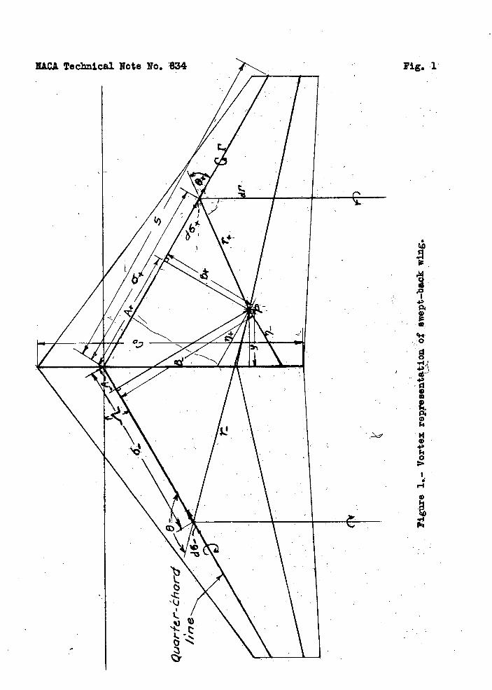
Pig. 1
9
-0
IT
L 4-)
43 Cf.4
"-f I-I
4.-f
0.
.5 •1•4 43
".4
I
NACA Technical Note No. 834
Pig. 2
ts
a)
Wa)
Wa) 000 OOU
..-I,-I 434-,
Wa) -.
4 a a 00000u - 10 oc n - to t9
'd' d 4
ki - 00 04'
--
o 4.3 44.) P44- 4 43 4.3 +
120l r1
i-4 r.4 •000 0 r.4•'
lit
It
lit
II, I.. .,
• '\- :' .
• _ ___ ____ I I_I_I
cz, CO
a)
.1 0
.1-I
.4.3
as
.4.,
p
a
I)
.4,
".4
or
0 .0)
x:
MOMMER&A 0 MIN,4a•IISri•IR rii
Mm VIUUIUJUS SHOWINNIMEMuuwiiuu
EMERIMMEMMIRREFUMEMEM
so•I!UIII]UUIUU MEM111IMMEME ON MENEM
onuuiiiuiuuii somriiuuaiuuaau MEMO,ONMEMIERNMEMEME ERNEMEMEN WEEKIMMEME rij ME I MEMMENNUMMEME Emm"MIMMEM FRIMINEME sm-lammu 0 mmmmommom WREAMSHEMIN
momillsommomitiii•a•ucL o. co c• cc
- -
N&CA Technical Note No. 834
Fig. 3
00 t)
0.4 -I
-1 If)
Pd
cc
D 0 .11)
.4
V to C
o - .0 0
+ .0 C Id
cc0.
o cc It 0.
o I0 cc
• 0 o 0
-I•) #
II .0 ...I
•3
•cj - V
0 .00 n .o Id
• 0
0.