mw1 series intelling untiversal breakers - markari.com · air circuit breaker ... c s e r i e s a c...
TRANSCRIPT

Number of Poles
Rated current of circuit breaker’s frame size
Design serial number
Air circuit breaker
Zhejiang MKM electric limited company
Type Specification
ClassificationAccording to the mounting: fixed and draw-out
According to the poles: three pole, four pole.
According to the operation ways: AUTO and Manual (at maintenance and repair)
According to the release: intelligent over current controller, under-voltage instantaneous (or delay)
release, and shunt release.
The capability of the intelligent over-current controller:
a) classification: H type(normal), M type(normal intelligent), L type(economic)
b) with the function of overload long delay, short delay, fixed and instantaneous reverse time limit
Protection
c) single phase earthed protective function
d) indication function: setting current indication, action current indication and voltage of each wire
indication (please mention indication function when you make an order)
e) Alarm function: overload alarm
f) Self-diagnostics function: overheating and pc self-diagnostics.
g) Test function: Testing the action characteristic of controller.
Environment condition for operation and installation
Ambient temperature: -5℃~40℃, and average temperature in 24 hours below +35℃(except for special
orders)
Elevation of installation site: ≦2000m
Relative humidity: Not exceeding 50% at the maximum ambient temperature of +40℃. With lower
temperature, higher humidity would be permitted, but the lowest average temperature in a month not
exceeding +25℃ during the most moist month, and the maximum monthly average relative humidity not
exceeding 90% in that month, and giving consideration to the dews on the goods surface which could
appear due to the temperature change.
Pollution protection: IP30.
Application category: B or A type.
Installing categories: Ⅳ for rated working voltage 660V(690V) and below breaker's main circuits, coils of
under voltage release and primary circuit of transformers. Ⅲ for other auxiliary circuits and control
circuit.
Installing condition: the breaker should be installed according to stipulations in operation manual. For
breakers in common use, the vertical gradient is not more than 3°.
ZHEJIANG MKM ELECTRIC CO.,LTD.001/
MC
CB
Se
ries
AC
B S
erie
sM
CB
Se
ries
AT
S S
erie
sLoad-isolating S
eriesC
ontrol Appliance Series
MW1 Series Intelling Untiversal Breakers
Mw1 series intelligent universal circuit breakers/air circuit breaker (hereinafter called ACB) suits the
circuit of AC 50Hz, rated voltage 660V(690V) and below, rated current 400A-6300A distribution net and
it's used to distribute and protect circuit. It could also protect current supply device against overload,
under-voltage, short current and single-phase earthing. MW1 ACB has intelligentized protecting system,
accurate selectivity protection and it could increase power distribution reliability and avoid unnecessary
power failures. At the same time, MW1 series also has open communication interface which could
realize “Four Remote”, remote checking, remote regulating, remote control and communications in order
to satisfy collective control center and automatic system. The impulse withstand voltage of this ACB is
8000V in altitude of 2000m(diffirent mounting altitude, the impulse withstand voltage is differ, pls refer to
the standard, the Max. should be more than 12000V).
Varied intelligent controller offers various functions. the breaker has disconnecting function if does not
have intellighent controller and sensor, its corresponding symbols is shown as
Application
Product executive standard: IEC60947-2, GBI4048.2
Rated working voltage: AC690V and below
Mounting manner: fixed and draw-out
Intelligent controller: H type(normal), M type(normal intelligent), L type(economic)
Breaking capacity: 80KA 100KA ( virtual value)
Pole of number: 3pole 4pole
Release type: several type intelligent release provide different function
Frame current: 2000 3200 4000 6300
Rated current: (400A) 630-6300A
Products comply with IEC60947-2 GB14048.2 standard
Rated frame current Inm(A) Rated currentIn(A)
40
50
60
400A 630A 800A 1000A 1250A 1600A 2000A
400A 630A 800A 1000A 1250A 1600A 2000A
400A 630A 800A 1000A 1250A 1550A 1900A
400A 630A 800A 1000A 1250A 1550A 1800A
(0.4-1)In (0.4-15)In ±10%
In-50kA(Inm=2000A)
In-75kA(Inm=3200A)
In-750kA(Inm=4000A)
In-100kA(Inm=6300A)
±15%
Inm=2000~6300A
(0.2-0.8)In
(Max1200A,Min160A)
±10%
1.05Ir1 1.3Ir1 1.5Ir1Setting time S 15 30 60 120 240 480
>2h No action <1h Action 2.0Ir1Setting time S 8.4 16.9 33.7 67.5 135 270
Technical Data and Capability
Seeing Table 1 for Rated current of ACB
2000 (400)630、800、1000、1250、1600、2000
3200 2000、2500、2900、3200
4000 4000
4000/4 4000
6300 4000、5000、6300
Table 1
The rated short circuit breaking capability and short time withstand of the breakers, the arcing distance is
“zero”. (As the outside of the breaker is no arcing.)
Table 2
Rated frame current InmInm(A)
Rated limit short circuit breaking capabilityIcu(kA)O-CO
Rated working short circuit breaking capabilityIcs(kA)o-co-co
Rated short time withstand Icw current(kA) 0.4s,O-CO
400V
690V
400V
690V
400V
690V
2000
80
50
50
40
50
40
320/4000
100
65
80
65
80
50
6300
120
85
100
75
100
75
Note: the input and output wire are the same for the breaking of the capability.
The maximum dissipation power is 360W for the breakers, and in the different temperature, the rated
sustained current would change.
Ambient temperature℃Rated Current
M type intelligence over current controller protection feature and functions.
Protection feature and functions of over current controller
Seeing Table 4 for the Setting value Ir (I/In) and error
Table 3
Table 4
Long delay Ir1
Short delay Instantaneous Earthed fault
Error Error ErrorIr2 Ir3 Ir4
Notice: if there are three steps protection at the same time, the setting value couldn't across.
2 2Long delay over current inverse time operation feature I TL=(1.5Ir1) TL, and its action time(1.02-2-
0)Ir1shown as below, has time error is ±15%.
Table 4
Notice: tL-is long delay setting time of 1.5lr1; TL- is long delay action time.
Short delay over current operation feature
Short delay over current operation is constant time lag. If low multiple is inverse time, its characteristic 2 2should be I TS=4(Irl) ts, ts is common long delay design time and Ts is short delay action time. When the
overload current is ﹥8Irl, it would be converted to constant time lag, has time error is ±15%. See Table 6
for its constant time lag
Rated short time withstand Icw current(kA) 0.4s,O-CO
MC
CB
S
eri
es
AC
B S
eri
es
MC
B S
eri
es
AT
S S
eri
es
Load
-isol
atin
g S
erie
sC
ontro
l App
lianc
e Se
ries
www.mkm-electric.com /002

0.1 0.2 0.3 0.4 0.06 0.14 0.23 0.35
Table 6
Delay time(S) Returnable time(S)
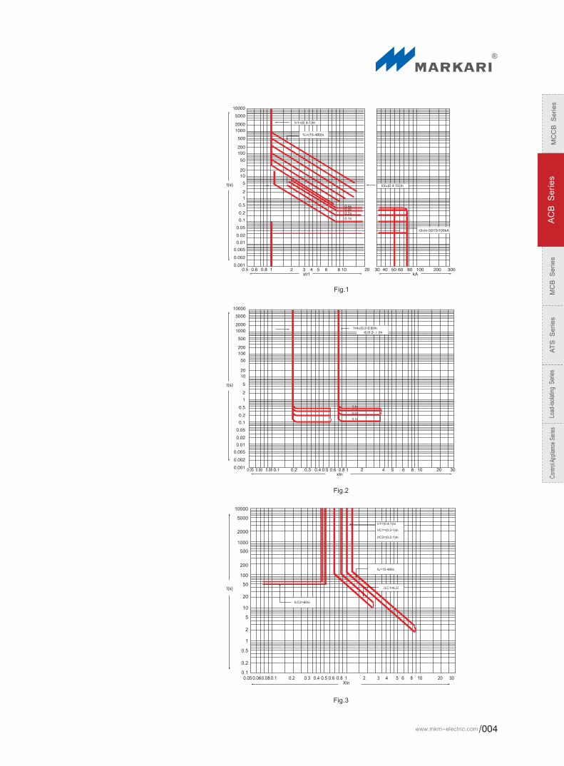
Over current release protection feature and functions, please refer to Fig. 1, earthed fault protection feature
and functions, please refer to Fig. 2.
M type intelligence over current controller protection feature and functions
Ammeter function: demonstrate each phase working current and earthed leaking current, show the
maximum phase current normally and the current or time when it's setting up, testing and making an
error.
Voltmeter function: indicate kinds of voltage of each wire and show the maximum normally.
Remote control and self-diagnostics function:
The controller has its own error self-diagnostics function: it would send error signal by “E” to indicate or
alarm when PC is making an error. And you could disconnect the circuit if you need when you restart
your computer.
When partial environment temperature partial runs up to 80℃, it could send alarm signal and disconnect
the circuit when lesser currents via. (For special orders)
Intelligent controller has overload, earthed, short circuit, load monitor, predicted alarm, release indication
(OCR) and etc. and all of the signals could be output through electrical contact or optical coupling which
would be convenient for user to connect external remote control unit. The electrical contact's capacity is
DC28V, 1A, AC125V, 1A.
Setting up function:
Use “set”, “+”, “_” and “save” these 4 buttons to set up all the parameters of the controller. Press “set up”
to the status you want to set (the status light would be on), and then press “+” or “_” button to adjust the
parameter to required value, then press “save” button. When “save” button light is on, the setting has
been locked up. The protection parameters of the controller couldn't be set up crosswise. When the
controller is back to reset after power cuts, press “set” button again and then check the setting
parameters circularly.
Testing function:
Use “set”, “+”, “_”, “release” and “unreleased” these buttons to check kinds of protection function and
feature of the controller and use “set”, “+”and “_” buttons to adjust a simulated failure test current.(Note:
don't press “save” to lock) and then use “release” or ” unreleased” buttons to test, the controller would go
ahead recovery processing. Press “release” button, the circuit would break. Press “unreleased” button,
the circuit wouldn't break and all the indication status are normal. If you want to do other test, please
press “return” or “clean” button after the test.
Note: for testing convenience, whether the earth leakage is setting in releasing or alarming position, the
test regards them as releasing treatment and the PRI is less than overload protection. In case there's
some error occurs during the testing, the controller would cut off the entire test automatically and then do
the recovery processing.
Load monitoring function:
Set two settings, ILC1 setting range (0.2-1) in and ILC2 setting range (0.2-1) In. the delay characteristic
of ILC1 is inverse characteristic, it's time setting is 1/2 of long delay setting; the delay characteristic of
ILC2 has two characteristics: one is inverse delay characteristic, it's time setting is 1/4 of long delay
setting. And the other is constant time lag; its delay time is 60S. The other delay function: the former is
used for disjunction junior unimportant load when the current is close to overload setting. And the latter is
used for making delay disjunction junior unimportant load when the current is beyond ILC1 setting, the
current would be decreased and keep the main circuit and important load circuit in power supply. When
the current is decreased into ILC2 and then gives the order to reconnect the circuits that have been cut
off after a certain delay, then recover the power supply of the entire system. There are two patterns of the
load monitoring from which users could choose one at random. About the monitoring characteristic,
please refer to fig.3 and 4, MCR release and imitate release protection. According to the special needs, it
could be shut off when doing the short delay releasing test.
MCR connecting and disjunction protection is mainly used for the switch off when the circuit is in error
status (the moment as the controller is turn on the power), the controller has the function to release the
circuit in low power short circuit current. The factory setting is 10KAm and the error is ±20%.(The other
setting could be done for the special needs.)
The controller has the function to send the releasing signal directly without the core's slice handling
when it is in super short circuit current.
Heat memory function
The controller has the mock duplex metal characteristics' memory function before the controller is
powered down when overloading and short circuit delay releasing. And the load energy would release
and finish short circuit in 30 minutes. The releasing time would be shorten, the controller would be power
down and the energy would be zero clearing when there's overloading and short delay during the
process.
a.
b.
c.
d.
e.
f .
g.
h.
ZHEJIANG MKM ELECTRIC CO.,LTD.003/
MC
CB
Se
ries
AC
B S
erie
sM
CB
Se
ries
AT
S S
erie
sLoad-isolating S
eriesC
ontrol Appliance Series
MW1 Series Intelling Untiversal Breakers
Fig.1
Fig.2
Fig.3
MC
CB
S
eri
es
AC
B S
eri
es
MC
B S
eri
es
AT
S S
eri
es
Load
-isol
atin
g S
erie
sC
ontro
l App
lianc
e Se
ries
www.mkm-electric.com /004
0.1 0.2 0.3 0.4 0.06 0.14 0.23 0.35
Table 6
Delay time(S) Returnable time(S)
Over current release protection feature and functions, please refer to Fig. 1, earthed fault protection feature
and functions, please refer to Fig. 2.
M type intelligence over current controller protection feature and functions
Ammeter function: demonstrate each phase working current and earthed leaking current, show the
maximum phase current normally and the current or time when it's setting up, testing and making an
error.
Voltmeter function: indicate kinds of voltage of each wire and show the maximum normally.
Remote control and self-diagnostics function:
The controller has its own error self-diagnostics function: it would send error signal by “E” to indicate or
alarm when PC is making an error. And you could disconnect the circuit if you need when you restart
your computer.
When partial environment temperature partial runs up to 80℃, it could send alarm signal and disconnect
the circuit when lesser currents via. (For special orders)
Intelligent controller has overload, earthed, short circuit, load monitor, predicted alarm, release indication
(OCR) and etc. and all of the signals could be output through electrical contact or optical coupling which
would be convenient for user to connect external remote control unit. The electrical contact's capacity is
DC28V, 1A, AC125V, 1A.
Setting up function:
Use “set”, “+”, “_” and “save” these 4 buttons to set up all the parameters of the controller. Press “set up”
to the status you want to set (the status light would be on), and then press “+” or “_” button to adjust the
parameter to required value, then press “save” button. When “save” button light is on, the setting has
been locked up. The protection parameters of the controller couldn't be set up crosswise. When the
controller is back to reset after power cuts, press “set” button again and then check the setting
parameters circularly.
Testing function:
Use “set”, “+”, “_”, “release” and “unreleased” these buttons to check kinds of protection function and
feature of the controller and use “set”, “+”and “_” buttons to adjust a simulated failure test current.(Note:
don't press “save” to lock) and then use “release” or ” unreleased” buttons to test, the controller would go
ahead recovery processing. Press “release” button, the circuit would break. Press “unreleased” button,
the circuit wouldn't break and all the indication status are normal. If you want to do other test, please
press “return” or “clean” button after the test.
Note: for testing convenience, whether the earth leakage is setting in releasing or alarming position, the
test regards them as releasing treatment and the PRI is less than overload protection. In case there's
some error occurs during the testing, the controller would cut off the entire test automatically and then do
the recovery processing.
Load monitoring function:
Set two settings, ILC1 setting range (0.2-1) in and ILC2 setting range (0.2-1) In. the delay characteristic
of ILC1 is inverse characteristic, it's time setting is 1/2 of long delay setting; the delay characteristic of
ILC2 has two characteristics: one is inverse delay characteristic, it's time setting is 1/4 of long delay
setting. And the other is constant time lag; its delay time is 60S. The other delay function: the former is
used for disjunction junior unimportant load when the current is close to overload setting. And the latter is
used for making delay disjunction junior unimportant load when the current is beyond ILC1 setting, the
current would be decreased and keep the main circuit and important load circuit in power supply. When
the current is decreased into ILC2 and then gives the order to reconnect the circuits that have been cut
off after a certain delay, then recover the power supply of the entire system. There are two patterns of the
load monitoring from which users could choose one at random. About the monitoring characteristic,
please refer to fig.3 and 4, MCR release and imitate release protection. According to the special needs, it
could be shut off when doing the short delay releasing test.
MCR connecting and disjunction protection is mainly used for the switch off when the circuit is in error
status (the moment as the controller is turn on the power), the controller has the function to release the
circuit in low power short circuit current. The factory setting is 10KAm and the error is ±20%.(The other
setting could be done for the special needs.)
The controller has the function to send the releasing signal directly without the core's slice handling
when it is in super short circuit current.
Heat memory function
The controller has the mock duplex metal characteristics' memory function before the controller is
powered down when overloading and short circuit delay releasing. And the load energy would release
and finish short circuit in 30 minutes. The releasing time would be shorten, the controller would be power
down and the energy would be zero clearing when there's overloading and short delay during the
process.
a.
b.
c.
d.
e.
f .
g.
h.
ZHEJIANG MKM ELECTRIC CO.,LTD.003/
MC
CB
Se
ries
AC
B S
erie
sM
CB
Se
ries
AT
S S
erie
sLoad-isolating S
eriesC
ontrol Appliance Series
MW1 Series Intelling Untiversal Breakers
Fig.1
Fig.2
Fig.3
MC
CB
S
eri
es
AC
B S
eri
es
MC
B S
eri
es
AT
S S
eri
es
Load
-isol
atin
g S
erie
sC
ontro
l App
lianc
e Se
ries
www.mkm-electric.com /004

Cp5611
Fig.4
H type intelligent controller
H type could serialize the communication connector which could be made up to hypotactic LAN system while it owns all the functions of M type. There
are 1 or 2 computers to be the main station and several intelligent circuit breakers or other CIM to be the secondary station. The system network
structure, please refer to the fig. below. The system could realize “four remote” functions about the circuit breaker unit. The monitoring aims to kinds of
electric network and action parameters and circuit breakers current action status, kinds of protection limit value's adjustment and decline, and the
intelligent circuit breakers' release and close controlling and etc. The system is applied to the power distribution system's construction and transform of
kinds of power station, power plant, small medium electric power substations, industrial and mining establishments and building and etc. Special
protocol connector's linking relationship, please refer to Diagram 3.
Seeing the following Figure 6 for the Connected diagram of Breaker basing on the universal DP agreement
Computer main station
RS485/RS232 converter or connecter
Communication terminal AB
The secondary station #1 of
Mw1 ACB
Communication terminal AB
The secondary station #2 of
Mw1 ACB
Communication terminal AB
The secondary station #3 of
Mw1 ACB
Upper manager
DP Mould
MW1 lntelligent breaker Other productinterace
DP Mould DP Mould DP Mould
MW1 lntelligent breaker MW1 lntelligent breaker
Fig.5
Fig.6
ZHEJIANG MKM ELECTRIC CO.,LTD.005/
MC
CB
Se
ries
AC
B S
erie
sM
CB
Se
ries
AT
S S
erie
sLoad-isolating S
eriesC
ontrol Appliance Series
MW1 Series Intelling Untiversal Breakers
Hardware structure of the data communications network system.
The intelligent breakers supply the standard RS485 communication interface from 10# and 11# output.
Communicate ambient of the system connection: kind A STP.
Network main features:
Bi-directional and serial data transfer mode.
The strict principal and subordinate way, as the principal station is sponsor and controller of the
communication,
The communicate baud rate is 9600bit/s, and communicate distance is 1.2km, and for the special baud
rate as PROFIBUS-DP is 187.5kbit/s.
Monitor software:
YSS 2000 software can depend on the different project, to realize the using monitor management. As for
the intelligent breakers, it can realize working monitor operation and several kinds daily manage
function.
System structure
a.
b.
c.
System function
Remote control:
It is the operating control, which is to control the each subordinate station breaker's restore, close and
open by from the principal station. The operator chooses the relative objective from the system interface,
and uses the mouse to press the remote button. The time order and the subordinate station will send the
result to the principal station about the remote control.
Remote adjust:
It is the setting of protection fixed value of the subordinate station through principal station. In the
principal station, there is the protection fixed value of the subordinate station. The operator chooses the
relative object from the system interface, and uses the mouse to press the remote button. The operator
import the code and it will send the orders “close” and “open”. The order will be sent to the subordinate
station, and operating follows the time order, and the subordinate station will send the result to the
principal station about remote control. Then the principal station will its protection fixed value.
Remote test:
It tests the network working parameter of the subordinate station through principal station. The
subsidiary of the communication can send the working parameter to the upper: the current of the A, B,
and C, N phase, the voltage of the
Fault memory:
It can memory these parameter, the current of the A, B, C, N phase, the voltage of the
type of the malfunction, operation time of the malfunction, and put them into the databank.
The fault current, voltage of the subsidiary station show as stick pictures and absolute value by the
computer. And the working state will be shown as factual curve.
Remote communication:
The principal checks the subordinate station for the type, close, breaking state, each protection fixed
value, working state, and malfunction information state. And the subordinate will send the parameters
are type, state (make or break), malfunction information, alarm information and several protections
setting fixed value.
Other functions of the system:
Besides four remote functions, the system has several management functions: accident alarm
(information screen, picture pull, accident dial and sound alarm), note affair, and so on.
UAE, UBC and UCA.
UAE, UBC and
UCA,
a.
b.
c.
d.
e.
L type intelligent controller
It adopts the setting way of coding switch and stir switch, and has overload long delay, short circuit short
delay, instantaneous, earthed leakage four steps protection features, malfunction state, load current light
standard indication. But it does not have the digital indication.
Operation characteristic
The cycle times of the operation MCCB, please refer to Table 7.
Table 7
Rated frame degree current(A) Operating cycle total times
2000
3200、4000
6300
10000
10000
8000
MC
CB
S
eri
es
AC
B S
eri
es
MC
B S
eri
es
AT
S S
eri
es
Load
-isol
atin
g S
erie
sC
ontro
l App
lianc
e Se
ries
www.mkm-electric.com /006

(0.35~0.7)Ue
(0.85~1.1)Ue
≤0. 35Ue
36VA 24VA
AC220
(0.7~1.1) Ue
1.3
30ms
24VA
AC
DC
220
380
220
6300VA
60W
Ac380 AC220 AC220
(0.85~1.1)Ue
≤200W
≤5s
Accessories:
under-voltage release
It is consist of under-voltage release coil and control modules
According to the working method: Instantaneous and delayed
The delay time is 1s, 3sand 5s. From 5s to 9s is taken as special model.
Within one half time delay, when the power voltage of the main circuit recovers to 85% Ue or above, the breaker does not Off.
Rated working voltage(Ue)
Action voltage
Reliable closing voltage
Reliable Off voltage
Power dissipation
AC380 AC220
Shunt release
Remote control to make break
Rated control power voltage(V)
Action voltage(V)
Instantaneous current
Breaking time
Power dissipation
AC380
0.7
36VA
AC110
1.3
24VA
≤
Closing electromagnet
After stored energy, the closing electromagnet can make the stored-energy spring force of operation mechanism instantaneously energy releases. so
that quickly close the circuit breaker
Rated control power voltage(V)
Action voltage(V)
Instantaneous current
Breaking time
power dissipation
AC380
0.7
36VA
≤
AC110
1.3
24VA
Ac220
(0.7~1.1) Ue
1.3
70ms
24VA
Electrical operatorThe breaker is with electrical energy storage and automatical energy re-storage function Circuit breaker is with energy manual storage function
Rated control power voltage(V)
Action voltage(V)
Power dissipation
Storage time
85W/110W/150W I / II /III
Auxiliary switchRated value
Rated voltage(v) Conventional themal current (Ith A) Rated control capacity
Notes: The general type of auxiliary switch is provided with 4 conversion contacts to user, The special: 3 NC 3NO, 5 conversion contacts. 4 NCand4 NO
key lock
Circuit breaker may be breaking the lock button position in the press, when the circuit breaker closing operation can not be done.
User option, the factory to provide lock and key
One separate circuit breaker with one lock and key
Two circuit breaker use the same two locks and key
Three circuit breakers with the same three of the same locks and two keys
Notes: Key chain with ACB need to pull out the key, you must first press and hold the sub-brake button, the key anti-clockwise rotation, and then call
out the key.
Property
Property
Property
Property
ZHEJIANG MKM ELECTRIC CO.,LTD.007/
MC
CB
Se
ries
AC
B S
erie
sM
CB
Se
ries
AT
S S
erie
sLoad-isolating S
eriesC
ontrol Appliance Series
MW1 Series Intelling Untiversal Breakers
Closing megnetic
Auxiliary contact
Motor mechanism
Intelligent controller
Installed hole
Drawer
General descriptions of structure
The fixed circuit breaker is made up of contact terminal system, intelligent controller, manual operation system, electrical operation system and mounting card. The draw-out circuit breaker is made up of contact terminal system, intelligent controller, manual operation system, and electrical operation system and draw base. The circuit breaker is solid placement and has the feature of compact structure and minute extension. The contact system is seal into the insulating base, and each contact terminal is separated by insulating board to form an individual closet. And the intelligent controller, manual operation and electrical operation structure form each independent unit before them one by one. If one of them doesn't work, you could take the entire old down and then take the new one on.The draw-out circuit breaker is made up of insert circuit breaker and draw base. The guiding rail inside the draw base could be pushed in and pull out, the insert circuit breaker is on the guiding rail of the in and out draw. It links and connects the major loop through the insert generatrix and bridge type contact on the draw base.There are three operation positions for draw-out circuit breakers: “Connecting”, “testing” and “breaking” positions. The position change could be realized by handle's procession and out of procession and the three positions' indication could be realized by the handle display on the draw-out base' beam.The major loop and the secondary circuit could be connected when it's in “connecting” position. The major loop would be disconnected and be separated by insulating barrier; only the secondary circuit is connected and could run necessary action test. Both the major loop and the secondary circuit would be disconnected when it's in “breaking” position. The draw-out circuit breaker has mechanical interlocking. The circuit breaker could be closed when it's in “connecting” or “testing” position and it couldn't be closed during the middle position between connecting and testing. The full-face indictor chart, please refer to Fig.5.
Breaking down showing/return button
Closing button
Handlc for manual cncrgy storage
Breaking button
Energy storage/energy release indication
Closed/broken showing
Facc(black and whitc)
Device for passing in or not
Position indicator
Handle and holder
Fig.7
Under voltage release
Shunt release
Product instructure
MC
CB
S
eri
es
AC
B S
eri
es
MC
B S
eri
es
AT
S S
eri
es
Load
-isol
atin
g S
erie
sC
ontro
l App
lianc
e Se
ries
www.mkm-electric.com /008

Pull out lock stem Wear into the lock stem
The use of circuit breakers
The operating of the Drawer type
The insert operation of the circuit breaker
a. Pull out the guide
b. Put the circuit breaker on the rails in the figure below; please make sure put the two circuit breaker
seating cards stent protruding into the guide groove.
c. Then push the body of circuit breaker move into until can not go any farther.
d. Out of the handle, and fully inserted into the first hexagonal handle drawer handle holes Block.
e. Turning the handle clockwise until the position indicator to "connect" position, and can hear both sides
of the drawer with”kada”, pulling the handle back into the place.
Output operation of the circuit breaker
a.Firstly make the circuit breaker from the "connect" position to move to the "separated" position (the
handle counter-clockwise rotation)
b.After pull the handle, press the icon out of circuit breakers, when pulling the circuit breaker out,
because of the focus forward, make sure circuit breakers prevent from dumping and falling
c.Pull out the circuit breaker body, and then put back the rail.
The lock of the “separated” position of the drawer type circuit breaker(the user buy the lock by their
selves)
a.Pull out the lock icon according to the figure.
b.Penetrated through the padlock, when the circuit breaker will not be able to from the "separation"
movement to "test" or "connected" position
Fig.8-1 Fig.8-2
Fig.8-3 Fig.8-4
Fig.8-5 Fig.8-6
Fig.8-7
Fig.8-8 Fig.8-9
ZHEJIANG MKM ELECTRIC CO.,LTD.009/
MC
CB
Se
ries
AC
B S
erie
sM
CB
Se
ries
AT
S S
erie
sLoad-isolating S
eriesC
ontrol Appliance Series
MW1 Series Intelling Untiversal Breakers
Storage operation
a.Energy storage will be pulled on the handle 6 or 7 times up and down repeatedly, until the hearing,
"kada" sound, and when the hands do not feel anti-power, energy storage instructions show the
"Storage", energy end
b.After the end of storage, “storage, off energy” instruction will on the “storage” position.
c.Electric Energy Storage: After the power control loop, the electric energy storage automatically
immediately (control circuit automatically have access into the situation in pre-storage)
Sub-switch operation
Manually on-off operation
a.Closing: When the circuit breaker in the energy, the disconnected state, push the green “I” button,
circuit breaker switch, “sub-gates, switch on” indicator by the “O” to “I”. “Storage, release “ indicator from
“energy” to “release”
b.OFF: When the circuit breaker in the closed state, push the red "O" button, break indicator circuit
breaker from the "I" to "o".
Electrical on-off operation
a.Closing: When the circuit breaker in the energy, the disconnected state ,Rated voltage will be imposed
on the electromagnet switch to circuit breaker close
b.OFF: When the circuit breaker in the closed state, Rated voltage will be imposed on the shunt release,
so that circuit breaker off
Interlock mechanism (suitable fixed type and draw out type)
Stacked and interlocked with connecting rods
Remark:
1. Use 3 vertical installed circuit
breaker of lever chain
2.if 2 circuit breaker interlock
only move the top circuit breaker
Fig.8-10
Fig.8-11 Fig.8-12
Fig.9a
Base point
The base of circuit breaker
Diagram
Probable operation method
MC
CB
S
eri
es
AC
B S
eri
es
MC
B S
eri
es
AT
S S
eri
es
Load
-isol
atin
g S
erie
sC
ontro
l App
lianc
e Se
ries
www.mkm-electric.com /010

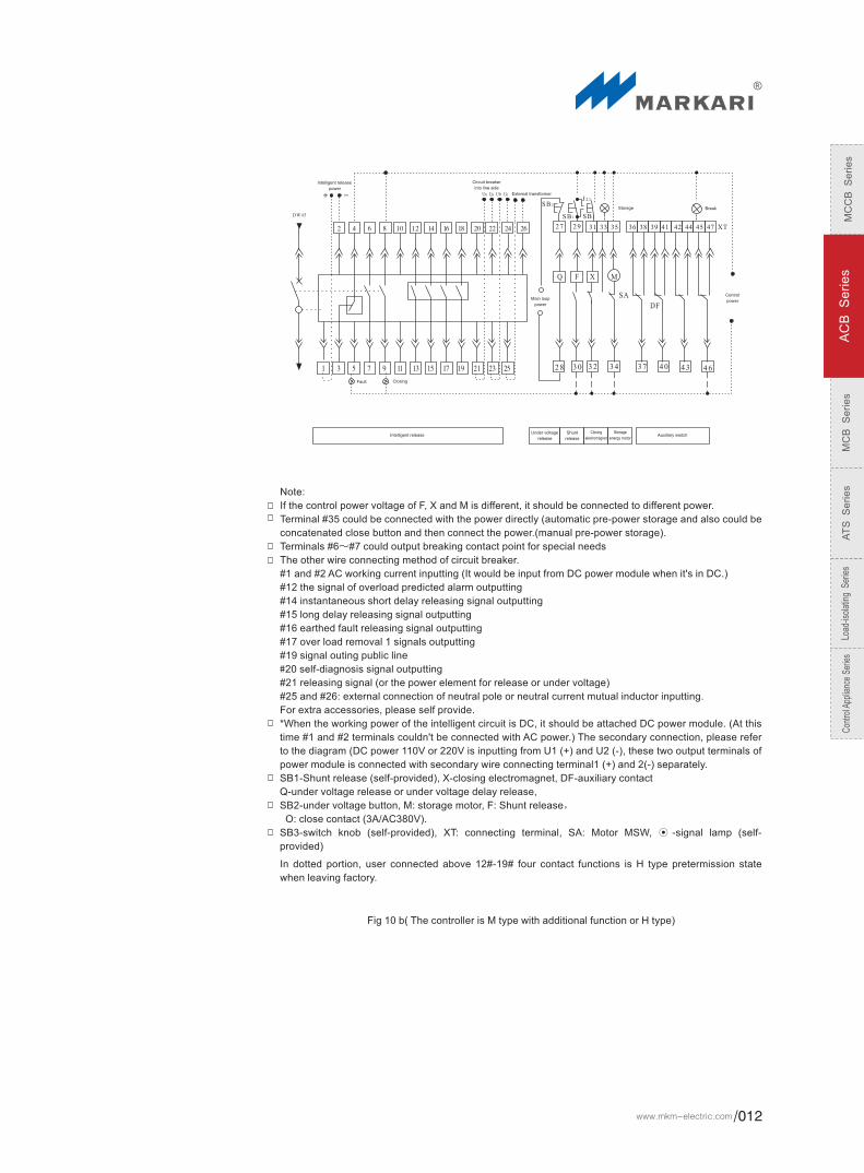
Soft interlock horizontal, vertical interlocks all can be provided, please refer to fig. 6b.
Wire connecting terminalThere are 47 overall wire connecting terminals for one circuit breaker,if required, that could be 51pcs.
And the connection is very simple and easy for the users. For the connection diagram, please refer to
Fig. 7a),b),c).
Note:
If the control power voltage of F, X and M is different, it should be connected to different power.
Terminal #35 could be connected with the power directly (automatic pre-power storage and also could be
concatenated close button and then connect the power.(manual pre-power storage).
Terminals #6~#7 could output breaking contact point for special needs.
For extra accessories, please self provide.
*When the working power of the intelligent circuit is DC, it should be attached DC power module. (At this
time #1 and #2 terminals couldn't be connected with AC power.) The secondary connection, please refer
to the diagram (DC power 110V or 220V is inputting from U1 (+) and U2 (-), these two output terminals of
power module is connected with secondary wire connecting terminal1 (+) and 2(-) separately.
The other connecting method of Intelligent controller:
#1 and #2 AC working current inputting (It would be input from DC power module when it's in DC.)
#25 and #26: external connection of neutral pole or neutral current mutual inductor inputting.
SB1-Shunt release (self-provided), X-closing electromagnet, DF-auxiliary contact
Q-under voltage release or under voltage delay release,
SB2-under voltage button, M: storage motor, F: Shunt release,
O: close contact (3A/AC380V).
SB3-switch knob (self-provided), XT: connecting terminal, SA: Motor MSW, ⊙ -signal lamp (self-
provided)
Fig.9b
Max
Auxiliary contactMotor close
Storage Break
Motor breakEmergency
breakIntelligent controllerMain loop
Fault
Clo
sing
Control
power
Handle
unit
Main loop
power
Working power
or
or
DC Power module
Fig 10 a( The controller is M type or L type basic function)
ZHEJIANG MKM ELECTRIC CO.,LTD.011/
MC
CB
Se
ries
AC
B S
erie
sM
CB
Se
ries
AT
S S
erie
sLoad-isolating S
eriesC
ontrol Appliance Series
MW1 Series Intelling Untiversal Breakers
Note:
If the control power voltage of F, X and M is different, it should be connected to different power.
Terminal #35 could be connected with the power directly (automatic pre-power storage and also could be
concatenated close button and then connect the power.(manual pre-power storage).
Terminals #6~#7 could output breaking contact point for special needs
The other wire connecting method of circuit breaker.
#1 and #2 AC working current inputting (It would be input from DC power module when it's in DC.)
#12 the signal of overload predicted alarm outputting
#14 instantaneous short delay releasing signal outputting
#15 long delay releasing signal outputting
#16 earthed fault releasing signal outputting
#17 over load removal 1 signals outputting
#19 signal outing public line
#20 self-diagnosis signal outputting
#21 releasing signal (or the power element for release or under voltage)
#25 and #26: external connection of neutral pole or neutral current mutual inductor inputting.
For extra accessories, please self provide.
*When the working power of the intelligent circuit is DC, it should be attached DC power module. (At this
time #1 and #2 terminals couldn't be connected with AC power.) The secondary connection, please refer
to the diagram (DC power 110V or 220V is inputting from U1 (+) and U2 (-), these two output terminals of
power module is connected with secondary wire connecting terminal1 (+) and 2(-) separately.
SB1-Shunt release (self-provided), X-closing electromagnet, DF-auxiliary contact
Q-under voltage release or under voltage delay release,
SB2-under voltage button, M: storage motor, F: Shunt release,
O: close contact (3A/AC380V).
SB3-switch knob (self-provided), XT: connecting terminal, SA: Motor MSW, ⊙ -signal lamp (self-
provided)
In dotted portion, user connected above 12#-19# four contact functions is H type pretermission state
when leaving factory.
Control
power
BreakStorage
Main loop
power
Fault Closing
Auxiliary switchStorage
energy motor
Closing
electromagnetShunt
release
Under voltage
releaseIntelligent release
Intelligent release
powerExternal transformer
Circuit breaker
into line side
Fig 10 b( The controller is M type with additional function or H type)
MC
CB
S
eri
es
AC
B S
eri
es
MC
B S
eri
es
AT
S S
eri
es
Load
-isol
atin
g S
erie
sC
ontro
l App
lianc
e Se
ries
www.mkm-electric.com /012

Overall and mounting dimension`
Overall and mounting dimension for fixed type, please refer to fig 11 and 12.
Fig.11 Overall and mounting dimension for fixde type(MW1-2000,2000/4)
Fig.12 Overall and mounting dimension for fixde type (MW1-3200,3200/4)
4P
3P
3P
4P
3P
4P
3P
4P
3P
4P
3P
4P
Vertical wiring
Level wiring
Vertical wiring
Level wiring
In
400-800A
1000-1600A
2000A
a mm
10
15
20
In
2000A,2500A
2900A,3200A
a mm
20
30
ZHEJIANG MKM ELECTRIC CO.,LTD.013/
MC
CB
Se
ries
AC
B S
erie
sM
CB
Se
ries
AT
S S
erie
sLoad-isolating S
eriesC
ontrol Appliance Series
MW1 Series Intelling Untiversal Breakers
Fig.13 Overall and mounting dimension for Drawer-out type(MW1-2000,2000/4)
Fig.14 Overall and mounting dimension for Drawer-out type(MW1-3200,3200/4)
4P
3P
4P3P
4P
3P
4P3P
4P
3P
4P
3P
Vertical wiring
Level wiring
Vertical wiring
Level wiring
In
400-800A
1000-1600A
2000A
a mm
10
15
20
In
2000A,2500A
2900A,3200A
a mm
20
30
Overall and mounting dimension for drawer-out type , please refer to fig.13~14.
Connected
Seperated
Connected
Seperated
Connected
Seperated
Connected
Seperated
MC
CB
S
eri
es
AC
B S
eri
es
MC
B S
eri
es
AT
S S
eri
es
Load
-isol
atin
g S
erie
sC
ontro
l App
lianc
e Se
ries
www.mkm-electric.com /014

Fig.15 Overall and mounting dimension for (MW1-4000,5000 3+3/3P)Drawer-out type
Fig.16 Overall and mounting dimension for (MW1-4000,5000 3+3/3P)Drawer-out type
Note:the size of the board center to circuit breaker center is 57.5
Connected
Seperated
Note:the size of the board center to circuit breaker center is 206.5
Connected
Seperated
ZHEJIANG MKM ELECTRIC CO.,LTD.015/
MC
CB
Se
ries
AC
B S
erie
sM
CB
Se
ries
AT
S S
erie
sLoad-isolating S
eriesC
ontrol Appliance Series
MW1 Series Intelling Untiversal Breakers
注: 面板中心致断路器中心
左右尺寸为246.5
Fig.17 Overall and mounting dimension for (MW1-6300+3/3P)Drawer-out type
Fig.18 Overall and mounting dimension for (MW1-6300 In=6300A)Drawer-out type
Please refer to Diagram 12 for MW1 User connective copper specification and quantity.
Rated currentExternal copper line type Each pole number Rated current
External copper line type Each pole number
Table 8
630A
800A
1000A
1250A
1600A
2000A
2500A
40 X 5
50 X 5
60 X 5
80 X 5
100 X 5
100 X 5
100 X 5
2
2
2
2
2
3
4
2000A
2500A
3600A
4000A
5000A
6300A
100 X 5
120 X 5
120 X 5
120 X 5
100 X 5
120 X 5
3
3
4
4
6
6
3P
4P
3P4P
3P
4P
Connected
Seperated
Note:the size of the board center to circuit breaker center is 189(3P)、246.5(4P)
Level wiring
Level wiring
Note:the size of the board center to circuit breaker center is 246.5
MC
CB
S
eri
es
AC
B S
eri
es
MC
B S
eri
es
AT
S S
eri
es
Load
-isol
atin
g S
erie
sC
ontro
l App
lianc
e Se
ries
www.mkm-electric.com /016
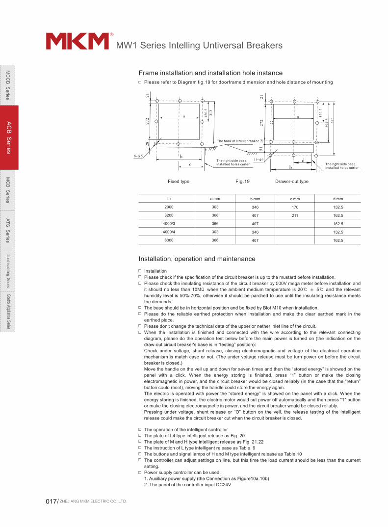
Please refer to Diagram fig.19 for doorframe dimension and hole distance of mounting
Fig.19
In
2000
3200
4000/3
4000/4
6300
a mm
303
366
366
303
366
b mm
346
407
407
346
407
c mm
170
211
d mm
132.5
162.5
162.5
132.5
162.5
Installation, operation and maintenance
Installation
Please check if the specification of the circuit breaker is up to the mustard before installation.
Please check the insulating resistance of the circuit breaker by 500V mega meter before installation and
it should no less than 10MΩ when the ambient medium temperature is 20℃ ± 5℃ and the relevant
humidity level is 50%-70%, otherwise it should be parched to use until the insulating resistance meets
the demands.
The base should be in horizontal position and be fixed by Blot M10 when installation.
Please do the reliable earthed protection when installation and make the clear earthed mark in the
earthed place.
Please don't change the technical data of the upper or nether inlet line of the circuit.
When the installation is finished and connected with the wire according to the relevant connecting
diagram, please do the operation test below before the main power is turned on (the indication on the
draw-out circuit breaker's base is in “testing” position):
Check under voltage, shunt release, closing electromagnetic and voltage of the electrical operation
mechanism is match case or not. (The under voltage release must be turn power on before the circuit
breaker is closed.)
Move the handle on the veil up and down for seven times and then the “stored energy” is showed on the
panel with a click. When the energy storing is finished, press “1” button or make the closing
electromagnetic in power, and the circuit breaker would be closed reliably (in the case that the “return”
button could reset), moving the handle could store the energy again.
The electric is operated with power the “stored energy” is showed on the panel with a click. When the
energy storing is finished, the electric motor would cut power off automatically and then press “1” button
or make the closing electromagnetic in power, and the circuit breaker would be closed reliably.
Pressing under voltage, shunt release or “O” button on the veil, the release testing of the intelligent
release could make the circuit breaker cut when the circuit breaker is closed.
The operation of the intelligent controller
The plate of L4 type intelligent release as Fig. 20
The plate of M and H type intelligent release as Fig. 21.22
The instruction of L type intelligent release as Table. 9
The buttons and signal lamps of H and M type intelligent release as Table.10
The controller can adjust settings on line, but this time the load current should be less than the current
setting.
Power supply controller can be used:
1. Auxiliary power supply (the Connection as Figure10a.10b)
2. The panel of the controller input DC24V
Frame installation and installation hole instance
The back of circuit breaker
The right side base installed holes certer The right side base
installed holes certer
Fixed type Drawer-out type
ZHEJIANG MKM ELECTRIC CO.,LTD.017/
MC
CB
Se
ries
AC
B S
erie
sM
CB
Se
ries
AT
S S
erie
sLoad-isolating S
eriesC
ontrol Appliance Series
MW1 Series Intelling Untiversal Breakers
The setting of the L type controller
The long time delay overload setting current Ir1 following Ir1 setting coding switch, if the code switches
Numerical arrow 0.8, then Ir1 = 0.8 * In. Note: In the entire time, coding must switch to digital.
Action time of the long time delay overload setting tL: fluctuations in the allocated side tL code switch
setting; the whole time value and the value corresponding to the following tL.
The remaining section of the protection of the entire set of parameters and overload protection of the
long time delay similar.
The test before using:
Intelligent release put into operation in the former, in order to check the release system intact case of the
smart user instantaneous release test release.
Test Method: "Clear" and then click "Test", intelligent release of instantaneous release, Ir3 bright red
light.
After the end of the trial click the "Clear" to enter the running state; at the same time it must be red
"reset" circuit breaker to be closed
The failure checking of the L type intelligent release:
"Clear" and then click "failure check" button, the system shows faults of the previous section, "that
section of the red light"
Press "Clear" button from the failure to check the status and return to operational status.
The display checking of the L type intelligent release.
"Clear" and then click "failure check" button, followed by six under the "test" button, wait a little longer all
the light-emitting diode should be lit.
M type, H type intelligent release
1.The setting of M and H type Intelligent release
--the overload long delay current setting of the controller: press “clear” button and then press “set”
button till the long delay status light (Ir1) is on and show the long delay factory current setting value,
generally it should be “In” ;. Press “+” and “-” button, the sliding scale is ≤2A once until it's close to
needed current. On top of that, press “save” button and then the storage indication light is on once and
off which means the long delay current setting value is finished saving.
--The setting of overload long delay time setting (tL): press “set” button again and the long delay time
status indication green light would be on and show the long delay time factory setting value (15s). Press
“+” for once, the time would be double added. If the time is too long, press “-” button. The time would be
double reduced for once. On top of that, press “save” button and then the storage indication light is off
which means the long delay time setting is finished saving.
The protect action and action time setting method of load monitoring, short delay, instantaneous, earthed
and etc. is same as above except the different corresponding status indication.
Such as short circuit protection short delay current Ir2 setting short-delay short-circuit state of the
corresponding indicator light "Ir2" yellow light, and its action time setting time corresponds to the state of
its actions "tS" yellow light, and so on
The earthed time setting is in “off” position which means the fault status and earthed one is only alarming
but no release. The instantaneous setting is in “off” position which means the protection is been
cancelled. The controller has the function of self lock key and then goes into error handling status in
case there are error signals during the setting process.
Intelligent release set in the whole process, once the line broke down, setting function will be blocked
automatically entered to deal with line fault, and has been stored by setting the value of the
implementation of the protection.
Intelligent release set in the whole process, once the line broke down, setting function will be blocked
automatically entered to deal with line fault, and has been stored by setting the value of the
implementation of the protection.
The protection of Intelligent Release After setting parameters, and then a "clear" button, the system is
running immediately; if setting after pressing any key, over a minute, the system will automatically return
to the running state.
The test of the M and H type controller
--After the parameters of the controller is set and before the circuit running, User could check all kinds
of protection function of release according to special needs. For the controller testing, there is “release”
or “unreleased” for choice. Press “release” button to test, the circuit breaker would be cut; and press
“unreleased” button which wouldn't send the releasing signal and the circuit breaker wouldn't cut. (Note:
L type only has release testing, press “test” button and the controller would send instantaneous signal
and the circuit breaker would cut.)
--For overload long delay test, press “set” button till the long delay status light is on. Check overload
setting value and to the other current status. Press “+” and “-” button to adjust the current to ﹥ 1.3Irl and
press test button into overload testing status. Click on the "release" or "Non-release" button, when the
"pilot" yellow light (that has been out of state during the trial) have been set to start trial long time delay,
intelligent overload long delay release according to the law of inverse-time extension when the action,
action time, depending on the protection of characteristic curves by the expression of the corresponding
calculated characteristics. During the process of overload long delay current overload indicator "Ir1"
flashing yellow light; when the time comes action, fault state "Ir1" the red light (if it is a test release, the
release issued by breaking move to make circuit breakers and colleagues " Trip "flashing red lights that
MC
CB
S
eri
es
AC
B S
eri
es
MC
B S
eri
es
AT
S S
eri
es
Load
-isol
atin
g S
erie
sC
ontro
l App
lianc
e Se
ries
www.mkm-electric.com /018

have been release), the end of the trial.
The controller's delay action is according to inverse time lagging system and point out the fault type and
testing status. The other characteristics testing are the same. At this time the turns of digital tube display
delay time and the pilot current action. Similar to other protected characteristics test, the test is different
from the process of flashing yellow lights of different status, different from the end of the trial of the fault
status light red .After the testing is finished, press “clear” button and go into normal operating status. At
the same, you have to press mechanism “return” button to cut the breaker.
Note: test results of intelligent release is not memory
The other operating rules of the controller
In the course of the experiment, only the "TEST" yellow light, other status indicators are not flashing
yellow light, ammeter will show a window "NODO", said the pilot to adjust the current value is too low,
testing is not running, this time to be in accordance with "clear" button to return to operational status
After the end of the trial click the "clear" button that is, into the normal operation of the state, in the case
of release experiments, it must also be in accordance with mechanical red "reset" button before closing
circuit breakers
Intelligent release of the trial process, once a fault line, it will automatically enter the Fault testing and the
abolition of the state.
M and H type intelligent release fault checking
"Clear" and then click the "failure check" button, the system will display the turn of the last failure state of
fault current and fault movement time; at this time press the "Select" button can be found at the time of
the last failure of the phase current value and the failure the impact of the harmonic coefficients. Press
"Clear" button from the failure to check and return to operational status.
M and H type intelligent release fault of display checking
"Clear" and then click the "display check" button, All devices should be light, let go” display check”,
system to immediately return to the running state.
M and H type intelligent release the voltage query (With voltage display)
"Clear" and then click the "query" button, Cycle with voltage meter display window: line voltage Vab, line
voltage Vbc, line voltage vca. Phase voltage va. Phase voltage vb, phase voltage vc, the frequency,
Maximum line voltage.
Click "Clear”, out of Voltage parameters from the query state and return to operational status
Intelligent Release Priority protection
Intelligent Release Priority protection: Short-circuit instantaneous> short-circuit short delay>
asymmetric grounding>overload long delay
Other instruction of the intelligent release
a. Once intelligent release to deal with the state of line fault, all keys have been blocked, press any key
at this time are of no use
b. Intelligent release in a variety of functional status (with the exception of the state line fault handling)
will be able to automatically enter the corresponding line fault line fault status
c. Intelligent release in a variety of functional status (with the exception of the state of things to deal with
line fault) in the case by "clear" can be instantly returned to operational status; if not press any keys
automatically after 1 minute to return to operational status
Intelligent release issued after the release action, we must click the "Clear" button, and then go on the
red machine "reset" button before closing circuit breakers
Maintenance of intelligent release
a. Intelligent release request should be careful to operate
b. M and H type intelligent release test in the entire set or after the protective cover should be sealed.
c. Connections should be periodic inspection of the fastening parts of the situation and, if loose, it is
timely to fastening
d. Occasions, the use of the United States and the ambient temperature and humidity must be consistent
with the relevant provisions.
e. To ensure that the line fault can be accurate and reliable protection, periodic tests should be intelligent
release.
Attention:
1.When Installation, please pay attention to protecting the controller, dust, moisture, to prevent
mechanical damage
2. Re-set parameters, the three current protection setting may not be cross-set,Should be: Ir1 <Ir2< Ir3
3. Before Putting into operation, should ask the professionals should be set to check whether the correct
parameters, the controller has been clear, reset, circuit breakers have to enter the normal state, and
tests. Operation should be diligent in observation, failures and anomalies found in a timely manner.
4. After fault tripping, should be based on the information panel display the prompt to remove the causes
of fault before they are allowed to re-enter the run.
ZHEJIANG MKM ELECTRIC CO.,LTD.019/
MC
CB
Se
ries
AC
B S
erie
sM
CB
Se
ries
AT
S S
erie
sLoad-isolating S
eriesC
ontrol Appliance Series
MW1 Series Intelling Untiversal Breakers
1
2
3
4
5
6
7
8
9
10
11
12
13
14
15
Code
Return button
Name Function
“Fault checking” button
TEST
Clear
Ir1
Ir2
Ir3
Ir4
tL
tS
tG
MCU lamp
“40-100”lamp
“overload” lamp
“Ir1-Ir4”fault lamp
Press it if the circuit breaker needs to close again after releasing, otherwise the controller couldn't close.
断路器脱扣分断后,需将此按钮按下去才可再次闭合断路器
Press this button to indicate or display the last fault status and error current or time value after the controller is cleared. Press “choose” button to check the error current or time circularly.
Which is used for checking the good coordinate situation between controller and circuit breaker.
Press this button after error testing or the circuit breaker's closing and make the release in a normal running status.
long delay current setting value
Short delay current setting value
Instantaneous current setting value
Earthed protection current setting value.
Long delay time setting value
Short delay time setting value
Earthed protection time setting value
Constant green light show the microcontroller (MCU) to normal work, the green light blinking, the blinking frequency of the microcontroller for self-diagnosis error code
The group light indicator for the load current, load current and Ir1 shows the percentage of the value
The red light indicates that the load current over load long delay protection, and the protection begin or alarm began.
In actual operation, the red light of a failure Always has been that the failure of the region, intelligent release issued instructions exclaimed; flashing red light if some fault that is delayed action or fault alarm, fault inspection, a failure before the red light of a single fault that occurred in the region; in the transient test exclaimed, instantaneous fault red light "Ir3" Liang said analog instantaneous release has occurred
1
2
3
4
5
6
7
8
9
10
11
12
13
14
15
16
17
18
19
Code Name
Return button
“Choose” button
“Clear” button
“Set” button
Display checking
“Fault checking” button
“Release”
“unreleased” buttons
“Store”
“+” and “-” buttons
“A” lamp
“KA” lamp
“S” lamp
“L1.L2.L3” lamp
“MAX” lamp
“G” lamp
“test” lamp
“release” lamp
“Load 1” lamp
Function
Press it if the circuit breaker needs to close again after releasing, otherwise the controller couldn't close
which could indicate all kinds of current and voltage value circularly under normal running status and indicate all kinds of error current and time value circularly under error or error checking status
Press this button after error testing or the circuit breaker's closing and make the release in a normal running status
which is used for checking or setting kinds of protection characteristics current or operation time. Press this button to indicate kinds of status circularly.
This button is used for light-emitting components of the inspection, this key, all parts are at the same time the LED light
Press this button to indicate or display the last fault status and error current or time value after the controller is cleared. Press “choose” button to check the error current or time circularly.
Which is used for testing function of release
Which is used for testing function of no release
For store all the setting of the data.
which is used for set the current and time
Show the value of current value and units of amperes (A), this green
Show the value of current value and units for 1000 amperes (kA), this green
Show the value of time value, the green phase, units of seconds (s)
One of three green lights that shows the current value of the phase current
The green light that shows the current value is the maximum of these three-phase
1.The Constant green light that shows the current earth fault protection for the asymmetry of the actual current value2.The blinking green light that shows the impact of harmonic coefficient value is the measured value of K
Yellow lamps Shows that is the course of test
Red light shows that the intelligent release has done the tripping action, and break off the circuit breaker yet,
1.In the process of tuning, the yellow light that is a load current setting ILc12.During the trial process, the flashing yellow light shows the load 1 monitor test is during the delay state, from the flashing to delay Always test that the time has come for action3.During the working process, the flashing yellow light shows the load 1 monitor test is during the delay state sent off a load of the relay signal
The panel structure and component function of circuit breaker controller L type M type and H type
Table 10 The push button and indicate lamp function of M type and H type release (see fig.21 and 22)
Reset
Testing
Fault checking
Testing Clear lamp
Intelligent controller
Fig.20 L4 type panel instructure of intelligent release
Fault checking
Intelligent controller
Reset
Testing
Red light
Red light
Yellow light
Red light
Red light
Yellow light
Yellow light
Yellow light
Yellow light
Yellow light
Yellow light
Storage green light
Trip No trip Storage
select
Trip
Fault
Clear lamp
Overload1 Overload2 Fault check
Adjustable Adjustable
Display checkSetup
Fig22 the panel instructure of M type and H type intelligent controller(with voltage display)
Fig21 the panel instructure of M type and H type intelligent controller(without voltage display)
Intelligent controller
Reset
Testing
Red light
Red light
Yellow light
Red light
Red light
Yellow light
Yellow light
Yellow light
Yellow light
Yellow light
Yellow light
Storage green light
Trip No trip Storage
select
Trip
Fault
Clear lamp
Overload1 Overload2 Fault check
Adjustable Adjustable
Display checkSetup
MC
CB
S
eri
es
AC
B S
eri
es
MC
B S
eri
es
AT
S S
eri
es
Load
-isol
atin
g S
erie
sC
ontro
l App
lianc
e Se
ries
www.mkm-electric.com /020
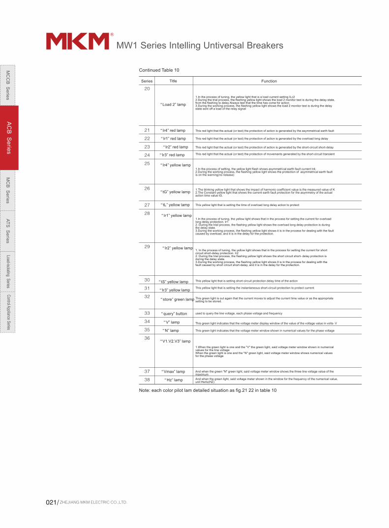
20
21
22
23
24
25
26
27
28
29
30
31
32
33
34
35
36
37
38
“Load 2” lamp
“Ir4” red lamp
“Ir1” red lamp
“Ir2” red lamp
“Ir3” red lamp
“Ir4” yellow lamp
“tG” yellow lamp
“tL” yellow lamp
“Ir1” yellow lamp
“Ir2” yellow lamp
“tS” yellow lamp
“Ir3” yellow lamp
“store” green lamp
“query” button
“V” lamp
“N” lamp
“V1.V2.V3” lamp
“Vmax” lamp
“Hz” lamp And when the green light, said voltage meter shown in the window for the frequency of the numerical value, unit Hertz(HZ)
And when the green "N" green light, said voltage meter window shows the three line voltage value of the maximum
1.When the green light is one and the "V" the green light, said voltage meter window shown in numerical values for the line voltageWhen the green light is one and the "N" green light, said voltage meter window shows numerical values for the phase voltage
This green light indicates that the voltage meter window shown in numerical values for the phase voltage
This green light indicates that the voltage meter display window of the value of the voltage value in volts- V
used to query the line voltage, each phase voltage and frequency
This green light is out again that the current moves to adjust the current time value or as the appropriate setting to be stored.
This yellow light that is setting the instantaneous short-circuit protection to protect current
This yellow light that is setting short-circuit protection delay time of the action
1. In the process of tuning, the yellow light shows that in the process for setting the current for short circuit short-delay protection. Ir22. During the trial process, the flashing yellow light shows the short circuit short- delay protection is during the delay state.3.During the working process, the flashing yellow light shows it is in the process for dealing with the fault caused by short circuit short-delay, and it is in the delay for the protection.
1.In the process of tuning, the yellow light shows that in the process for setting the current for overload long delay protection. Ir12. During the trial process, the flashing yellow light shows the overload long delay protection is during the delay state.3.During the working process, the flashing yellow light shows it is in the process for dealing with the fault caused by overload, and it is in the delay for the protection.
This yellow light that is setting the time of overload long delay action to protect
1.The blinking yellow light that shows the impact of harmonic coefficient value is the measured value of K2.The Constant yellow light that shows the current earth fault protection for the asymmetry of the actual action time value tG.
1.In the process of setting, the yellow light flash shows asymmetrical earth fault current Ir4;2.During the working process, the flashing yellow light shows the protection of asymmetrical earth fault is on the warning(no release)
This red light that the actual (or test) the protection of movements generated by the short-circuit transient
This red light that the actual (or test) the protection of action is generated by the short-circuit short-delay
This red light that the actual (or test) the protection of action is generated by the overload long delay
This red light that the actual (or test) the protection of action is generated by the asymmetrical earth fault
1.In the process of tuning, the yellow light that is a load current setting ILc22.During the trial process, the flashing yellow light shows the load 2 monitor test is during the delay state, from the flashing to delay Always test that the time has come for action3.During the working process, the flashing yellow light shows the load 2 monitor test is during the delay state sent off a load of the relay signal
Note: each color pilot lam detailed situation as fig.21 22 in table 10
Continued Table 10
Series Title Function
ZHEJIANG MKM ELECTRIC CO.,LTD.021/
MC
CB
Se
ries
AC
B S
erie
sM
CB
Se
ries
AT
S S
erie
sLoad-isolating S
eriesC
ontrol Appliance Series
MW1 Series Intelling Untiversal Breakers
Application
Brief MW1-3 type intelligent controller( hereinafter called intelligent controller) is a new developed a new
generation intelligent controller which with LCD, its hardware and software are improved and optimized
on the base of KST-2 intelligent controller, it carry on mature and steady kernel of KST-2 intelligent
controller, and make a big improve in power parts and display, reduce the power consumption of
machine, and further increase the stability, raise voltage protection function.
Basic functionFor SM type intelligent controller, basic function deploy without any selection functions see table 11:
Basic function deploy
Protection and monitor Measure Maintain Human-computer interface
Short instantaneous protection
Short delay constant time lag protection
Curve short delay inverse time lag protection
Curve long delay protection
Current disequilibrium protection
Asymmetry ground protection( vector sum)
Neutral phase protection
MCR and HSISC protection
Overload monitor( manner 1)
Under voltage protection
Overload voltage protection
Voltage disequilibrium protection
3(4) phase current
Asymmetry ground current
Long delay thermal capacity
Phase/wire voltage
Voltage disequilibrium
Frequency
Series
Power
Power factor
Current waveform
Electric network harmonic influence coefficient
8 times faulty records
8 times faulty records
8 times faulty records
Main contact fret valent weight
Operation times
Trip times
System clock
Faulty self check
Wire break self check
Chinese figure LCD
LED state instruction
Keyboard operation
Elect function
Elect function Function explanation Remark
Communication
4 teams contact output function
Use KST programmer
Leakage protection function
Other protection
Required value measure and protect
Add communication function based on 3M type intelligent controller,
including Modbus-RTU communication protocols, can join externally
P- or – protocols transfer modules to make remote communication
function several open communication protocols come true.
intelligent controller including 4 team passive contact, the function can be programmed.
In the DB9 connection of board use KST programmer
intelligent controller add leakage protection electric elements, leakage zero-sequence transformer, protect or alarm with leakage current
Under frequency, over frequency and phase series protection or alarm.
Measure required current pratical value, maximum value, can protect or alarm with required current
3H type, it is the neccessory function.
Cancel the Asymmetry ground protection function automatically
Table 12
Table 11
MC
CB
S
eri
es
AC
B S
eri
es
MC
B S
eri
es
AT
S S
eri
es
Load
-isol
atin
g S
erie
sC
ontro
l App
lianc
e Se
ries
www.mkm-electric.com /022

1
2
3
4
5
6
7
8
9
10
11
12
13
14
15
Symbol and meaning
Symbol and meaning see table 13
Means corresponding circuit breaker frame maximum rated current
Means circuit breaker rated current
In additional leakage mutual inductor rated current
Means long delay, short delay, inverse time lag and constant time lag, instantaneous setting current value respectively
Asymmetry ground or leakage setting current value
Means 3 phase current, 3 line voltage average value respectively
Means overload monitor1 , overload monitor 2 current setting value respectively
Means current unbalance rate, voltage unbalance rate respectively
Means long delay, short delay, inverse time lag and constant time lag setting current value respectively
Means Asymmetry ground or leakage , unbalance setting current value
Means Asymmetry ground or leakage inverse time lag coefficient
1)For 4 poles products, means N phase setting value
2) During overload inverse time lag property expression: means I/IR
Means 3 phase voltage
Means 3 phase voltage
Means A B C N 4 phase current
MW1-3 type intelligent controller function illustration
Protection functionAny protection tripped will be recorded, can through information enquiry to get the detailed parameter
and date, time when tripping.
Overload long delay protection propertyIntelligent controller overload long delay protection property technical parameter see table 14
Distribution and motor protection
Generator protection
N phase protection
Setting current value
Setting current value
Inverse time lag delay setting value tr(s)(corresponding 10 51r)
Inverse time lag delay setting value tr(s)(corresponding 10 51r)
Setting coefficient(note)
Action property
Property curve
Action property
Curve rate
Precision
Action property
Property curve
Curve rate
Precision
Ir=Inx...
Ir=Inx...
Note: when N phase protection setting coefficient is 50%, for N phase protection setting value is 50% of
A B C 3 phase. If overload delay setting current value is 1600A, phase protection setting value is 800A.
Heat memory (30min clear when power break)
Serial no Symbol Meaning
Inm
In
I
Ir, Is, Isd, Ii
IG
Iav, Uav
Ic1, Ic2
8I, 8V
tr, ts, tsD
tG, t8
KG
N
Uan, Ubn, Ucn
Uab, Ubc, Uca
Ia, Ib, Ic, IN
Overload long delay protection property technical parameter
≤1.05 Ir:>2h No action
>1.30 Ir:<1h Action
0.4~1.0+OFF(Exit situation)
IEC60255 standard,80top,setting
±10%
0.4~1.25+OFF(Exit situation)
≤1.05 Ir: >2h No action
>1.30 Ir: <1h Action
Curve setting1~6( )
3 setting curve 3 when leaving factory
IEC60255standard,80top,setting
100% or 50%(Suitable for 3P+N or 4P product)
Same as 3 phase protection property
Standard + OFF(close)
Curve setting1~6( )
3 setting curve 3 when leaving factory
±10%
Table 13
Table 14
ZHEJIANG MKM ELECTRIC CO.,LTD.023/
MC
CB
Se
ries
AC
B S
erie
sM
CB
Se
ries
AT
S S
erie
sLoad-isolating S
eriesC
ontrol Appliance Series
MW1 Series Intelling Untiversal Breakers
Intelligent controller provide 6 types overload protection property curve, expression as below:-Sistandard inverse time lag -VI fast inverse time lag
-Ei(G) posthaste inverse time lag( common use)
-Ei(M) posthaste inverse time lag( motor protection) -HV high voltage fuse element compatible
2-I t posthaste inverse time lag 2 ( common use)
0.02T=0.00814 t/(N -1)T=0.5 t/(N-1)
2T= 1.25 t/(N -1)2 2T=1.3974 t*In(N /(N -1.15))
4T=4.0625 t/(N -1 )2T=2.25 t/N
I.e. :T: actual protection delay action time valuet: inverse time lag delay setting value, each property curve inverse time lag setting value see table 15N: the rate of actual working current and overload long delay protection setting current value, just as..
Table 15: 6type overload protection property curve inverse time lag delay setting value
No.
overload protection property curve inverse time lag delay setting value
Delay action time when corresponding 1.5Ir
SI standard inverse time lag
VI fast inverse time lag
Ei(G) posthaste inverse time lag( common use)
Ei(M) posthaste inverse time lag( motor protection)
HV high voltage fuse element compatible
I2t posthaste inverse time lag 2 ( common use)
C01
C02
C03
C04
C05
C06
C07
C08
C09
C10
C11
C12
C13
C14
C15
C16
0.62
1.00
1048
2048
3.70
4.94
6.16
9.24
11.10
17.26
24.64
36.96
48.28
61.60
73.92
86.24
2.00
3.20
4.80
8.00
12.00
16.00
20.00
27.00
36.00
56.00
80.00
120.00
160.00
200.00
240.00
280.00
8.00
12.80
19.20
32.00
48.00
64.00
80.00
108.00
144.00
224.00
320.00
480.00
640.00
800.00
960.00
1040.00
6.24
9.98
14.96
24.92
37.36
49.82
62.28
84.06
112.00
174.30
249.00
373.60
498.10
622.60
747.20
809.40
2.48
3.94
5.92
9.86
14.78
19.70
24.62
33.24
44.32
68.94
98.48
147.70
196.90
246.10
295.40
320.00
15.00
20.00
25.00
30.00
40.00
50.00
60.00
80.00
100.00
120.00
160.00
200.00
240.00
320.00
400.00
480.00
For example:If one intelligent controller long delay protection setting conditions are: overload long delay protection
property curve is curve 3, Ir :2000A, tr: 48.00s, calculate actual faulty current 4000A overload long delay
action time Tr.N=I/Ir=4000/2000=2.0Tr=1.25tr/(N2-1)=1.25*48/(2.02-1)=20msOverload long delay action time is 20S under this conditions.Please note: when short current short delay constant time lag protection put into working, overload long
delay action time not less than short current short delay constant time lag setting value. If when short
current short delay constant time lag protection exist, overload long delay action time should not be
limited.( but not less than20ms)
2 short current short delay protection propertyIntelligent controller short current short delay protection property technical parameter see table 16
curve 1 curve 2 curve 3 curve 4 curve 5 curve 6
MC
CB
S
eri
es
AC
B S
eri
es
MC
B S
eri
es
AT
S S
eri
es
Load
-isol
atin
g S
erie
sC
ontro
l App
lianc
e Se
ries
www.mkm-electric.com /024
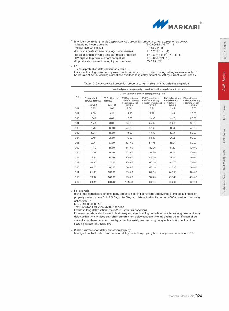

Short current short delay protection property
Inverse time lag setting current value
Constant time lag setting current value
Constant time lag delay setting value tsd
Inverse time lag protection property
Inverse time lag heated memory(15min,Clear when power break)
Action property
Action property
Precision
Short current short delay protection have 2 types:1.inverse time lag when faulty current more than inverse time lag setting current value, if it is curve (1-5), intelligent controller as per the curve (1-5) delay protection when overload long delay. Only the speed is 10 times faster, (tenth of delay action time which calculate as per overload long delay curve expression). I f it is curve 6, then as per short current short delay curve 6 property expression to calculate inverse time lag delay action time value.2.constant time lag: when faulty current more than constant time lag setting current value, intelligent controller delay protect as per constant time lag setting vaulue.For example: If one intelligent controller long delay protection setting conditions are: overload long delay protection property curve is curve 3, Ir :2000A, tr: 48.00s, the conditions of short delay protection setting is : IS 30000A IsD 5000A, actual faulty current is 4000A, intelligent controller short delay inverse time lag action, calculate by formula Tr=20S, and action time Ts=///2sPlease note: when set the inverse time lag setting current value in the OFF situation or constant time lag setting current value less or equal to inverse time lag setting current value, intelligent controller protect as per constant time lag, inverse time lag fail automatically. When constant time lag put into working, whatever constant time lag or inverse time lag protection, short delay protection delay action time all not less than constant time lag delay setting value. If when constant time lag protection in exist state, delay action time of inverse time lag don't limit by constant time lag delay setting value( but not less than 20ms)Short instantaneous protection propertyIntelligent controller short instantaneous protection property technical parameter see table 17
Short instantaneous protect property technical parameter
Note: when intelligent controller is I frame, instantaneous protection setting current value is 0FF, when intelligent controller is II frame, instantaneous protection setting current value is1.0In~75kA+OFF;when intelligent controller is III frame, instantaneous protection setting current value is 1.0In~100kA+OFF。
1.0In~50kA+
4. asymmetry ground or leakage protection propertyAsymmetry ground protection of intelligent controller have 2 types: vector sum( difference value) type (T), ground current type(W). T type detect zero-sequence current, select 4phase( 3 phase 4 wire) or 3 phase (3 phase 3 wire) current vector sum to protect; W type is through special external connect mutual inductor detect current in ground cable directly to protect.Intelligent controller leakage protection signal select from external zero-sequence mutual inductor directly. Leakage protection actual current value use secondary current of zero-sequence mutual inductor to display, no related with rated current of circuit breaker.Intelligent controller asymmetry ground or leakage protection property technical parameter see table 18
≤0.9Is:No action
>1.1Is:Delay action
1.5~15+OFF(Exit situation)
±10%
1.5~15+OFF(Exit situation)
≤0.9IsD Ir:No action
>1.1IsD:Delay action
0.1~1(Stage head 0.1)
Curve 1-5 like overload long delay, but the speed is 10 times faster
Curve 6 property expression: Ts=64tsD/N2
I.e. Ts=tsd*(8Ir/I)2
Standard + OFF( ) close
IsD=It X...
tsD(s)
Is=Ir X...
Setting current valueAction property
Ii=
Action time
1.0In~50KA/75KA/1I00KA+OFF(Exit situation)(note)
≤0.85Ii:No action
>1.15Ii:Action
100ms( )Including circuit breaker immanent breaking time
Table 17
Table 16
ZHEJIANG MKM ELECTRIC CO.,LTD.025/
MC
CB
Se
ries
AC
B S
erie
sM
CB
Se
ries
AT
S S
erie
sLoad-isolating S
eriesC
ontrol Appliance Series
MW1 Series Intelling Untiversal Breakers
Asymmetry ground or leakage protection property technical parameter
Asymmetry ground protection
Leakage protection
Setting current value
T type harmonic influence coefficient setting value
Delay setting value
Action property
Delay setting value
Note: T type asymmetry ground protection add harmonic influence coefficient( electric network influence 3 phase imitation current vector sum colligation coefficient) K setting item., when set K in OFF, asymmetry ground protection fully adopt 3 phase current imitation vector sum to protect, when in ON, asymmetry ground protection fully adopt 3 phase current digital vector sum to protect, when setting K in 10-100%, asymmetry ground protection reckon in this percentage harmonic influence procedure as actual ground current value to protect.
0.2~1+OFF(Minimum100A,OFF Exit situation)
0.8IG:No action
1.0IG:Delay action
ON+10%~100%+OFF(Stage head 1%)(note)
Precision
Precision
Action property
Action property
Harmonic influence coefficient K
Constant time lag delay tG(s) Inverse time lag coefficient KG
Inverse time lag coefficient KG
Constant time lag delay tG(s)
±10%
±15%
0.8IG:No action
1.0IG:Delay action
0.1~1+OFF
0.5~6+OFF
0.1~1+OFF
0.5~6+OFF
0.1~1+OFF
Asymmetry ground or leakage protection either-orAsymmetry ground or leakage protection have two types:Inverse time lag: protection property expression:TG=tG*KG*7GIn the expression: TG: actual protection delay action time value tG: constant time delay setting value KG: inverse time lag coefficient value IG: setting current value I: actual working currentInverse time lag protection delay action time calculate by above expression: but Inverse time lag protection delay action time not less than constant time lag delay setting value. If KG is OFF, it is constant time delay protection.Constant time delay: delay action time of constant time lag protection is constant time lag delay setting value.Current unbalance protection propertyCurrent unbalance protection of intelligent controller protect of phase failure and 3 phase current unbalance, as per unbalance rate among 3 phase current to protect and alarm.Current unbalance protection of intelligent controller technical parameter see table 19Current unbalance rate computing formula is : 8I=I-Iav/Iav In the formula, Iav is the average value of 3 phase currentCurrent unbalance protection property is constant time lag protection, delay setting value is t6,when ts is OFF,means Current unbalance protection only alarm not trip.
Current unbalance protection property technical parameter
Current unbalance rate starting value
Delay setting value
Action or alarm property
Delay setting value
Precision
t (s)
40%~100+OFF(Stage head 1%,OFF Exit situation)
≤0.98:No action
>1.18:Delay action
±10%
Table 18
IG=IΔX...
IG=In X...
Table 19
Rank difference 0.1,OFF means only alarming without trippingRank difference 0.5,OFF means earth leakage is constant time-lag
Rank difference 0.1A,OFF means exist
Rank difference 0.1,OFF means only alarming without trippingRank difference 0.5,OFF means earth leakage is constant time-lag
Rank difference 0.1,OFF means only alarming without tripping
0.1~1+OFF
MC
CB
S
eri
es
AC
B S
eri
es
MC
B S
eri
es
AT
S S
eri
es
Load
-isol
atin
g S
erie
sC
ontro
l App
lianc
e Se
ries
www.mkm-electric.com /026
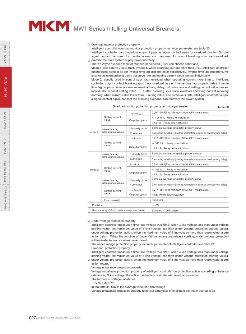
Overload monitor protection property
Intelligent controller overload monitor protection property technical parameter see table 20
Intelligent controller can procedure output 2 passive signal contact used for overload monitor. Out put
signal contact can used for monitor alarm, also can used for control breaking spur track overload,
promise the main system supply power normally.
There's 2 type overload monitor manner for selected.( user can choose either one)
Mode 1: can control 2 spur track overload, when operating current more than ..or.., intelligent controller
output signal contact as per inverse time lag property delay respectively. Inverse time lag property curve
is same as overload long delay but curve rate and setting current value can set individually
Mode 2: usually used in control spur track overload when operating current more than .., intelligent
controller output contact breaking spur track overload as per inverse time lag property delay. Inverse
time lag property curve is same as overload long delay, but curve rate and setting current value can set
individually, request setting value …, if after breaking spur track overload operating current recovery
normally, when current value lower than… setting value, anc continuous 60S, intelligent controller output
a signal contact again, connect the breaking overload, can recovery the power system.
Overload monitor protection property technical parameter
Mode 1
Mode 2
Setting current value
Setting current value
Setting current value
Setting current value
Fixed delay(s)
Precision
Inverse time lag setting current value(s)
Inverse time lag setting current value(s)
Inverse time lag setting current value(s)
Heat memory (30min clear when power break) Standard + OFF(close)
Output property
Output property
Output property
Output property
Property curve
Property curve
Property curve
Curve rate
Curve rate
Curve rate
Ic1=In X ...
Ic2=In X ...
Ic1=In X ...
Ic2=In X ...
Fixed 60s
±10%
0.2~1+OFF(The minimum 100A, OFF means exist)
0.2~1+OFF(The minimum 100A, OFF means exist)
0.2~1+OFF(The minimum 100A, OFF means exist)
0.2~1+OFF(The minimum 100A, OFF means exist)
>1.2 Ic1:Relay delay actuation
>1.2 Ic2:Relay delay actuation
>1.2 Ic1:Relay delay actuation
<Ic2:Relay delay actuation
≤1.05 Ic1: Relay no actuation
≤1.05 Ic2: Relay no actuation
≤1.05 Ic1: Relay no actuation
Same as overload long delay property curve
Same as overload long delay property curve
Same as overload long delay property curve
Can setting individually ( setting parameter are same as overload long delay)
Can setting individually ( setting parameter are same as overload long delay)
Can setting individually ( setting parameter are same as overload long delay)
Under voltage protection property
Intelligent controller measure 1 time loop voltage true RMS; when 3 line voltage less than under voltage
starting value( the maximum value of 3 line voltage less than under voltage protection starting value),
under voltage protection action; when the maximum value of 3 line voltage more than return value, alarm
action return. When the function of power-fail instantaneous release starting, under voltage protection
will trip instantaneously when power failed.
The under voltage protection property technical parameter of intelligent controller see table 21
Overload protection property
Intelligent controller measure 1 time loop voltage true RMS; when 3 line voltage less than under voltage
starting value( the maximum value of 3 line voltage less than under voltage protection starting value),
under voltage protection action; when the maximum value of 3 line voltage more than return value, alarm
action return.
Voltage unbalance protection property
Voltage unbalance protection property of intelligent controller do protection action according unbalance
rate among 3 line voltage, the action mechanism is similar with overload protection.
The formula of voltage unbalance:
8V=U-Uav/Uav
In the formula, Uav is the average value of 3 line voltage
Voltage unbalance protection property technical parameter of intelligent controller see table 23
Table 20
ZHEJIANG MKM ELECTRIC CO.,LTD.027/
MC
CB
Se
ries
AC
B S
erie
sM
CB
Se
ries
AT
S S
erie
sLoad-isolating S
eriesC
ontrol Appliance Series
MW1 Series Intelling Untiversal Breakers
Table21: under voltage protection property technical parameter
Under voltage protection starting value
Starting delay time value
Under voltage alarm return value
Return delay time value
Precision
Protection execute method Alarm/Trip/Close
Setting range(s)
Alarm property
Setting range(V)
Setting range(s)
Setting range(V)
Action and alarm property
±10%
0.2~60(stage head 0.1)
≥1.1×return value: alarm and return
<0.9×return value: alarm no return
starting value~1200(stage head 1)
0.2~60(stage head 0.1)
≤0.9 x starting value: delay action or alarm
>1.1 x starting value: no action or no alarm
100~1200(stage head 1)
Table 22: overload voltage protection property technical parameter
Under voltage protection starting value
Starting delay time value
Return delay time value
Precision
Protection execute method
Setting range(V)
Setting range(V)
Setting range(s)
Setting range(s)
Action and alarm property
Alarm property
100~1200(stage head 1)
>0.9 x starting value: no action or no alarm
≤1.1 x starting value: delay action or alarm
0.2~60(stage head 0.1)
starting value~100(stage head 1)
<1.1×return value: alarm no return
≥0.9×return value: alarm and return
0.2~60(stage head 0.1)
±10%
Alarm/Trip/Close
MCR ( making & breaking) and TTSISC( ultimate trip) protection function
making & breaking and ultimate trip of intelligent controller is reserve protection function. Both the two
protection mode are instantaneous action. The action value is related with the operation breaking and
limited breaking capacity of circuit breaker, making& breaking current usually is 40kA,60kA,80kA. Out of
limit trip current value is 50kA,75kA,100kA( 2 current when leaving factory: Ⅰ frame 40/50kA,
60/75kA,Ⅲ frame 80/100kA) faulty current signal through hardware to compare circuit to send out
action order directly, MCR only used in circuit breaker close instantaneously, but Out of limit trip protect
all the time after close 100ms.
Ⅱ frame
,
Voltage unbalance protection property technical parameter
Return delay time value
Precision
Protection execute method
Starting delay time value
Setting range(V)
Setting range(V)
Setting range(s)
Setting range(s)
Action and alarm property
Alarm property
Alarm/Trip/Close
±10%
0.2~60(stage head 0.1)
≤0.9×return value: alarm and return
>1.1×return value: alarm no return
starting value~2%(stage head 1)
0.2~60(stage head 0.1)
≥1.1 x starting value: delay action or alarm
<0.9 x starting value: no action or no alarm
2%~30%(stage head 1)
Table 23
Unequal voltage protection start value
Unequal voltage alarm return value
Over voltage alarm return value
MC
CB
S
eri
es
AC
B S
eri
es
MC
B S
eri
es
AT
S S
eri
es
Load
-isol
atin
g S
erie
sC
ontro
l App
lianc
e Se
ries
www.mkm-electric.com /028

Measure function
Real time value measure
Current value
Measure method
Measure each phase current RMS. Measure item including A phase current Ia,B phase current Ib,C
phase current Ic,N phase current In,ground faulty current or leakage current Ig
Measure range
A phase current,B phase current Ib,C phase current Ic,N phase current IN no less than 25 multiples rated
current In., ground faulty current or leakage current Ig no less than 10 multiples rated value.
Measure precision
In 2 multiplesr rated current In range, difference is ±1.5%, above 2 multiples rated current, difference is
i5%.
Current prismatical figure display
Intelligent controller shoe A B C(N) phase current value by prismatical figure under operating state, and
display the maximum phase current by digital. The height(percentage) of prismatical figure instruct the
percentage of each pahse current value and overload long delay protection setting current value(when
overload long delay protection closed).
Current unbalance rate
Current unbalance rate is measuring the unbalance percentage of 3 phase current. The formula is :
8I=(I-I)av/Iav
in the formula, Iav is average value of 3 phase current
Voltage value
Measure mode: measure each phase voltage RMS.
Measure range
line voltage( voltage between phase line and phase line):0V~1200V
Measure precision:±5%
Phase sequence
“A-B-C” and “A-C-B” forms to display three phase voltage phase sequence
Frequency
Measure range :45Hz~65Hz
Measure precision:±0.05Hz
Note:frequency signal select from A phase voltage
Voltage unbalance rate
Voltage unbalance rate is measuring the unbalance percentage of 3 phase voltage. The formula is :
6V=U-Uav/Uav
in the formula, Iav is average value of 3 phase line voltage
Active power
Measure contect
A phase active power
Measure precision±2.5%
Power factor
Measure contect
Phase power factor
Measure precision
±0.02
ZHEJIANG MKM ELECTRIC CO.,LTD.029/
MC
CB
Se
ries
AC
B S
erie
sM
CB
Se
ries
AT
S S
erie
sLoad-isolating S
eriesC
ontrol Appliance Series
MW1 Series Intelling Untiversal Breakers
Harmonic influence coefficient measure
harmonic influence coefficient (electric network influence 3 phase imitation current vector sum colligation coefficient) means electric network harmonic influence procedure to T type asymmetry ground protectionthe formula of harmonic influence coefficient real measure value is: K=(IAG-IDG)/Iz X 100% IAG: 3 phase current imitation vector sum value IDG: 3 phase current digital vector sum value Iz: asymmetry ground synthesized current value
Internal temperature measure
Internal temperature refers to small environment temperature value which nearby intelligent controller internal MCU, real time measure by temperature chip. When the temperature more than…, the system will appear “internal temperature excess temperature” alarm
System setup functionSystem clock function
System clock function is the basic setup function of MW1-3 type intelligent controller. The internal of controller have 3V lithium battery. So long as lithium battery have power, the external won't breaking, system clock reposition.
Measure meter setup functionSystem type selection
3type:system type: three-phase three-wire systemPoles no of circuit breaker: 3p -3∮3W3CT:system type: three-phase four-wire systemPoles no of circuit breaker: 3p -3∮3W3CT:system type: three-phase four-wire systemPoles no of circuit breaker: 4p or 3p+N -3∮3W3CT:
Internal temperature calibration
Internal temperature calibration should be proceeding when intelligent controller cold clean criticality. At that time the internal temperature is close to external environment temperature. When controller leaving factory, internal temperature had already adjusted, commonly user need to adjust again.
Communication transfer
3H intelligent controller elect 3M type intelligent controller which have KST programmer, can use KsT programmer in DB9 interface of board.It have 2 options:Communication with programmerCommunication with host computerOnly select communication with programmer, can unleash KsT programmer full efficacy.3H intelligent controller RS485 interface of 10# 11# line is same with RS485 which DB9 relative.( have a connection)
Test & lock functionAnalog experiment
Analog experiment have 3 test type: Three-section protection test : regulate test current( equal to failure current), starting test, when imitation overload long delay, short current short delay, short instantaneous faulty occurs, the protection conditions of intelligent controller. Ground or leakage protection test: regulate test current ( equal to failure current), starting test, when imitation ground or leakage faulty occurs the protection conditions of intelligent controller. Mechanism action time test: after starting test system enforce flux transfer trip action, to test mechanism action time of circuit breaker trip.Analog experiment have 2 test version: No trip test: when finish test, intelligent controller show test result information but don't trip, it suitable for field test which can not power cut. Trip test: when finish test, intelligent controller show test result information and trip, it suitable for field test which power cut.
MC
CB
S
eri
es
AC
B S
eri
es
MC
B S
eri
es
AT
S S
eri
es
Load
-isol
atin
g S
erie
sC
ontro
l App
lianc
e Se
ries
www.mkm-electric.com /030

Analog experiment technical parameter see table 24
Table 24: analog experiment technical parameter
Test type
Test version
Test current
Test control
Three-section protection
Ground or leakage protection
Asymmetry ground protection Leakage protection
No trip / Trip
Mechanism action time
Trip
None
Start/stop
0A~50KA(I Frame)/75KA(II Frame)/100KA(III Frame) 0A~99.99A
Situation lock
Parameter lock of intelligent controller have two states:
Parameter lock of intelligent controller have two states:Parameter lock: under this state, user only inquiry parameter but can not revise parameterParameter unlock: under this state, user can inquiry and revise parameterNote: in order to make all parameter of controller no unauthorized changes, ensure system operate reliably, its function adopt the password of consumer management.
Communication setup function
3H type intelligent controller can through Rs485 interface(10#,11# line or DB 9 interface of board) to achieve telemetry, remote control, remote regulating, remote signaling etc four remote functions. The communication interface adopt photoelectric isolation, suitable for strong electrical interfere environment.Communication setup technical parameter see table 26
Table 26: Communication setup technical parameter
Communication protocols
Communication module
Communication address
Baud rate
Internal
Self-adapting
External
ModbuS--RTU Profibus--DP Device Net
125K、250K、500K
0 63~3 126~0~225
9.6K、19.2K
I/O setup function3H type intelligent controller and 3M type intelligent controller which elect”4 teams contact output function” have 4 teams free from one another signal contact output, the output function can be setted. Provided signal contact output and output time see table 17intelligent controller 4 teams contact function pretermit state when leaving factory see table 18
Table 25 The limitation of position lock to operation
Operation types
Remote, regulate and control
Local parameter adjustable
Local test
Programming operation
Available
Available
Available Available
Unavailable Unavailable
Unavailable
Unavailable
Setup
Position lock state
Parameter lock
Remote
Available
Unavailable
Unavailable
Available
Local
ZHEJIANG MKM ELECTRIC CO.,LTD.031/
MC
CB
Se
ries
AC
B S
erie
sM
CB
Se
ries
AT
S S
erie
sLoad-isolating S
eriesC
ontrol Appliance Series
MW1 Series Intelling Untiversal Breakers
0
1
2
3
4
5
6
7
8
9
10(A)
11(B)
12(C)
13(D)
Table 27: intelligent controller signal contact output and output time
Function No. Signal contact output function
Undefinition
Short current instantaneous faulty trip alarm
Ground or leakage faulty trip alarm
Short current short delay faulty trip alarm
Overload long delay faulty trip alarm
Faulty trip alarm
Overload monitor 1 uninstall output
Overload monitor 2 uninstall output
System self-checking faulty alarm
Electric network faulty pre-alarm
Under voltage faulty alarm
Overload faulty alarm
Voltage unbalance faulty alarm
Signal contact output time
No output
Short current instantaneous faulty trip alarm output
Ground or leakage faulty trip( or alarm) output
Current unbalance( or alarm) output
Short current short delay faulty trip output
Overload long delay faulty trip output
Any faulty trip alarm output
Overload monitor 1 uninstall output
Overload monitor 2 uninstall output
System self-checking faulty alarm output
Protection or monitor delay output at first
Under voltage faulty alarm output when starting time arrived
Overload faulty alarm output when starting time arrived
Table 28: intelligent controller 4 teams contact function pretermit state when leaving factor
Contact no
Controller type
3M Type
3H Type
Contact 1 Contact 2 Contact 3 Contact 4
Overload monitor 1 uninstall output
Overload monitor 1 uninstall output
Overload monitor 2 uninstall output
Overload monitor 2 uninstall output
System self-checking faulty alarm
Faulty trip alarm Faulty trip alarm
Note: 3H type intelligent controller contact3, contact 4 fixed used in remote breaking, remote closing, can not set as other function.
Inquiry function Current alarmWhen “faulty/alarm” red light flash slowly, means intelligent controller have alarm information, can inquiry present alarm to show present exist alarm information.Intelligent controller display alarm information see table 29
Table 29: complete alarm information which can be show
Type
Self-checking faulty alarm
Self-checking serious faulty alarm
Protection alarm
Alarm information
External packet mistake
Modulus transfer mistake
Internal temperature excess
A phase mutual inductor wire break
B phase mutual inductor wire break
C phase mutual inductor wire break
N phase mutual inductor wire break
flux transfer trip wire break
Main contact damage
Separating brake mechanism failure to operate
Procedure packet mistake(note)
Ground or leakage faulty
Current unbalance faulty
Under voltage faulty
Overload faulty
Voltage unbalance faulty
Faulty pre-alarm
Note: when intelligent controller shows: Procedure packet mistake, it is means MCU of intelligent controller have a series faulty, and intelligent controller can not work normally, should be change in time.
Current Unbalance fault trip alarm
Fault trip alarm
Voltage unbalance faulty alarm output when starting time arrived
MC
CB
S
eri
es
AC
B S
eri
es
MC
B S
eri
es
AT
S S
eri
es
Load
-isol
atin
g S
erie
sC
ontro
l App
lianc
e Se
ries
www.mkm-electric.com /032

Programmatic interface function.
3H type intelligent controller and 3M intelligent controller which elect KST programmer, have the function of communication on the programmer with
connection. Through programmer can set system internal parameter, such as: overload protection property curve classification selection, open and
close of heated memory, signal contact output function setting, communication protocol selection, communication address setting, communication
baud rate selection, system clock adjust, setup function lock and unlock, voltage connection mode selection etc. also have test breaking & closing
function, history data check and setting value copy.
Related use of programmer can reference( programmer instruction for use)
Operation times
Accumulate breaking/closing of circuit breaker times, breaking 、closing once. This value can revise and clear with special method.
Main contact damage
Intelligent controller according faulty current, main contact construction etc date when tripping to analog computation the damage rate of main
contact. The display value of intelligent controller when leaving factory is 0%, means main contact no damage. Every time after faulty tripped,
intelligent controller deduct accordingly wear rate valent weight automatically. When wear rate value ≥40%, system will send out self-checking faulty
alarm signal, to remind user take maintain measure in time.
After change the main contact, can through programmer or specially method to recovery original wear rate value 0%.
Product information
Show intelligent controller manufacture informations
Trip record
Record the last 8 times trip faulty information and former measure parameter.
Record total faulty trip times. This value can be clear with special method.
The detailed information of each faulty trip record.
Faulty time(year, month, date, hour, minute, second)
Faulty type(reason)
Faulty original numerical value( such as faulty current value, faulty voltage value, faulty unbalance value etc)
Faulty delay time
Faulty phase
Faulty total time/ this time
Faulty measure parameter at that time
Alarm record
Record the last 8 times trip faulty information
The detailed information of each faulty trip record.
Alarm reason
Alarm time(year, month, date, hour, minute, second)
Alarm original numerical value( some without this item)
Metachoresis record
Record the last 8 times breaking/closing times
The detailed information of each metachoresis
Metachoresis type
Metachoresis reason
Metachoresis time(year, month, date, hour, minute, second)
Other functions
Display checking function
This function can check all working conditions of luminescent device, ensure luminescent device instruction correct, and display products information.
Detailed operation see 4.1.4
Wire break self-checking function
Intelligent controller can self-checking 3(4) phase hollow mutual inductor wire break and flux transfer trip wire break faulty.
Heated memory function
Repeating overload maybe lead to electrical conductor or device heated, intelligent controller imitate heated state, after overload long delay, short
current short delay etc faulty delay action, with pyrometric effect( imitate bimetallic strip property). Overload long delay pyrometric effect energy after
finishing fault resolution 30min release, short current short delay pyrometric effect energy after finishing fault resolution 15min release. During this
period if occurred overload long delay, short current short delay etc faulty when closing circuit breaker again, delay action time will be short, can the
circuit or device will be protect suitably.(as same as overload monitor heated memory property and overload long delay protection heated memory
property)
Pverload monitor heated memory display through present heat capacity. When present heat capacity value reached 100% then overload long delay
protect action.
If intelligent controller power cut and electrify again, accumulate pyrometric effect clear completely.
When leaving factory this property toleration is start, with heated memory function. Use can set by themselves.
ZHEJIANG MKM ELECTRIC CO.,LTD.033/
MC
CB
Se
ries
AC
B S
erie
sM
CB
Se
ries
AT
S S
erie
sLoad-isolating S
eriesC
ontrol Appliance Series
MW1 Series Intelling Untiversal Breakers
Db9 test connection
Board sketch
MW1-3H
MW1-3 type intelligent controller use method
mechanism reset button
LCD
Protect section red light
Faulty reset key
Faulty or alarm red light
Bus green light
Working normal green light
Operating parameter key
System setup key
Protection setup key
Information inquiry key
Confirm key
Exit key
Downwards key
Upwards key
Intelligent trip unit
Panel instructure
MC
CB
S
eri
es
AC
B S
eri
es
MC
B S
eri
es
AT
S S
eri
es
Load
-isol
atin
g S
erie
sC
ontro
l App
lianc
e Se
ries
www.mkm-electric.com /034

1 2
3
Board constitute , display and operation application
MW1-3 type intelligent controller board have 5 parts: LCD, LED pilot lamp group, keyboard,DB9 test connection and red mechanism reset button,
see board sketch.
LCD
Show all measure parameter in Chinese, system setup parameter, protection setup parameter and all information.
Top right corner of LCD have“ ”, means next display interface, press key to enter into next interface.
Top right corner of LCD have“ ”, means next display interface, press key to enter into last interface.
Top right corner of LCD have“ ”, means upwards downwards have display interface, press key to enter into last interface. Press key
enter into next interface
↓
↑
LED pilot lamp group
Protection section red light
When setting current protection, red light lighting means it is setting protection current value or delay time value in accordingly section.
When faulty delay or alarming, red light flash in normal speed means faulty delay or alarming in accordingly section.
After faulty protection tripped, red light flash faster means faulty tripped in accordingly section.
Faulty or alarm red light
Function of faulty or alarm red light
MW1-3 type “faulty or alarm red light” combined “ faulty pre-alarm”, “faulty trip”, “self-checking faulty pre-alarm” in performance. Use different flash
mode to distinguish faulty information and alarm information. When normally working, faulty or alarm red light don't light, i.e. when faulty or alarm
red light flash, system to be exceptional
Function of faulty or alarm red light different flash see table 30
Table 30: function of faulty or alarm red light flash meaning.
Series State of red light Meaning
Flash slowly (2s/time)
Flash normally (1s/time)
Flash fast (0.4s/time)
System has alarm or self-checking faulty information
Protect faulty delay (pre-alarm) state
Protect faulty trip state
Bus green light
Bus green light shows bus date delivery status. Lighting when deliver, off when without any bus data.
Normal working green light
Only electrify with intelligent controller, “normal working green light” flash normally all the time, if the light off or lighting permanently, the intelligent
controller working abnormally, should be changed immediately.
keyboard
Intelligent controller have 4 shortcut keyboard: operating parameter key, system setup key, protection setup key, information inquiry key, can
quickly transfer among 4 main menu, also have 5 operating key, details as below:
Quickly transfer to operation parameter main menu (timing system clock to leftwards key)
Quickly transfer to system setup main menu (timing system clock to rightwards key)
Quickly transfer to protection setting main menu
Quickly transfer to information inquiry main menu
Upwards: shift cursor upwards, or change selected parameter upwards, or location show leftwards
Downwards: shift cursor downwards, or change selected parameter downwards, or location show rightwards
Exit: exit present menu and return to previous menu, or cancel revise present parameter.
Conformation: enter into present cursor which point to next menu, or select present parameter, or storage the revision.
Reposition: when faulty tripped or alarm state enter into reposition state.
ZHEJIANG MKM ELECTRIC CO.,LTD.035/
MC
CB
Se
ries
AC
B S
erie
sM
CB
Se
ries
AT
S S
erie
sLoad-isolating S
eriesC
ontrol Appliance Series
MW1 Series Intelling Untiversal Breakers
DB9 test interface
test interface of intelligent controller board have 3 functions:
DC 24V power input:
Can input DC24V power directly, and can as a auxiliary power of intelligent controller. 4, 5 terminal of
DB9 interface connect anode, of DC power, ,2 9 terminal connect cathode( power line ground)
Analog signals input port
Can input 3 phase current analog signal directly, do current protection property test of intelligent
controller, 7 terminal of DB9 interface connect A phase current analog signal, 6 terminal connect B
phase current analog signal,,1 terminal connect C phase current analog signal,, 2 9 terminal are the
analog signal jointly.
Program and communication interface
3H type intelligent controller and 3M intelligent controller which elect MW1 programmer can use MW1
programmer on DB9 interface, also can communicate with host computer through this interface. 3
terminal of DB9 interface connect RS485-A terminal( equal to 10 # line), 8 terminal connect RS485-B
terminal(equal to 11 # line)
Red mechanism reposition button
Faulty tripped or test tripped this button will popping, when press this button, circuit breaker can close,
LCD back lightingLCD design no back lighting when electrify, so as to increase the intelligent controller working
reliability under no auxiliary power small current conditions.
Press any key can light back lighting, in any interface press and 2 keys meanwhile can close
back lighting, after 5 min close back lighting automatically without press any key.
LED pilot lamp full display state:
Under reposition (operation) interface press and 2 keys meanwhile, system enter into LED pilot
lamp full display state,
Under LED pilot lamp state, press key, return to reposition (operation) interface immediately,
without press any key, after 5 min system return to reposition (operation) interface automatically.
MW1-3H
MC
CB
S
eri
es
AC
B S
eri
es
MC
B S
eri
es
AT
S S
eri
es
Load
-isol
atin
g S
erie
sC
ontro
l App
lianc
e Se
ries
www.mkm-electric.com /036
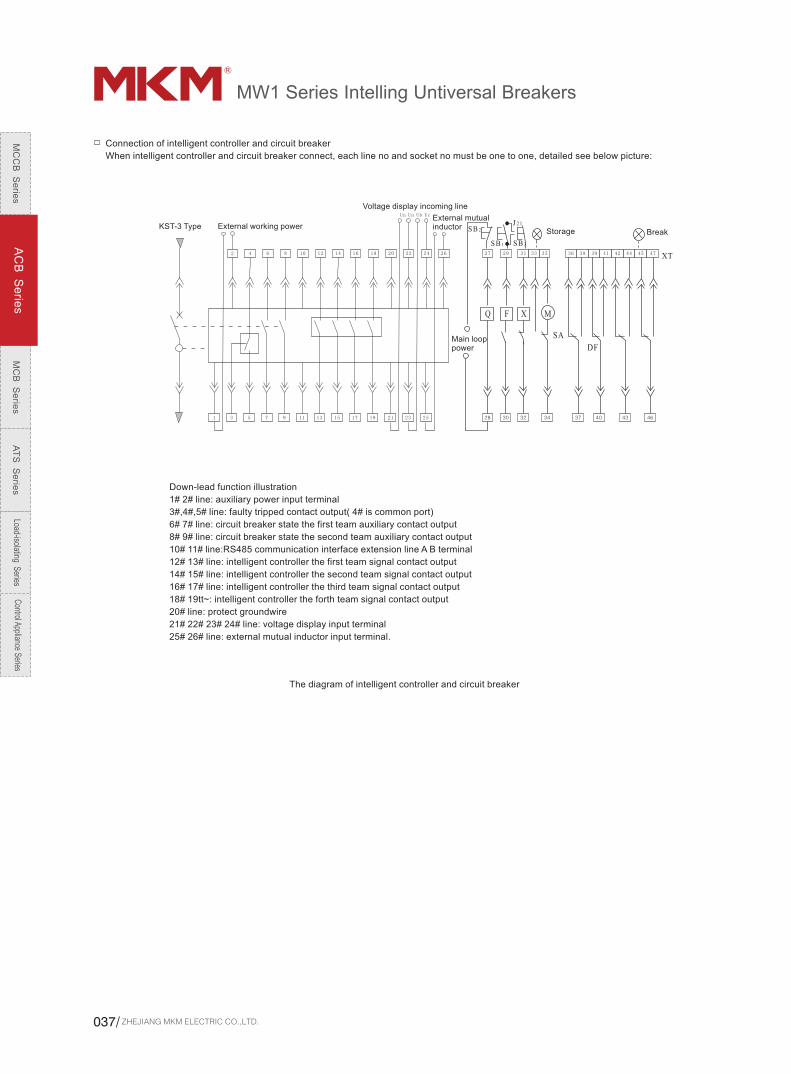
Connection of intelligent controller and circuit breaker
When intelligent controller and circuit breaker connect, each line no and socket no must be one to one, detailed see below picture:
External working powerKST-3 Type
Voltage display incoming line
External mutual inductor
Storage Break
Main loop power
Down-lead function illustration
1# 2# line: auxiliary power input terminal
3#,4#,5# line: faulty tripped contact output( 4# is common port)
6# 7# line: circuit breaker state the first team auxiliary contact output
8# 9# line: circuit breaker state the second team auxiliary contact output
10# 11# line:RS485 communication interface extension line A B terminal
12# 13# line: intelligent controller the first team signal contact output
14# 15# line: intelligent controller the second team signal contact output
16# 17# line: intelligent controller the third team signal contact output
18# 19tt~: intelligent controller the forth team signal contact output
20# line: protect groundwire
21# 22# 23# 24# line: voltage display input terminal
25# 26# line: external mutual inductor input terminal.
The diagram of intelligent controller and circuit breaker
ZHEJIANG MKM ELECTRIC CO.,LTD.037/
MC
CB
Se
ries
AC
B S
erie
sM
CB
Se
ries
AT
S S
erie
sLoad-isolating S
eriesC
ontrol Appliance Series
MW1 Series Intelling Untiversal Breakers
Common causes and solutions for the faults.
1. In the smart controller checks the value of breaking current time action.
2. Analysis of the case load and the power grid.
3. If the overload, please rule out the overload fault.
4. If it is the actual operating current and operating current of long time delay entire value does not match, please amend the operating current based on the actual operating current long time delay setting to match the appropriate protection.
5. Press the reset button to reset and re-closing circuit breakers。
1. In the smart controller checks the value of breaking current and the action time.
2. If short, please search for and rule out the possibility of short-circuit fault.
3. Inspection of the intelligent controller setting.
4. To check the status of circuit breakers in good condition.
5. Press the reset button to reset and re-closing circuit breaker.
1. In the smart controller checks the value of breaking current and the action time
2. If the earth fault find and rule out the possibility of ground fault
3. Modify intelligent ground fault current controller settings
4. If there is no earth fault conditions the fault current to check whether the setting to match the actual protection.
5. Press the reset button to reset and re-closing circuit breaker.
Mechanical interlocking action Check with mechanical interlocking of two circuit breakers work.
Ground Fault Trip (Ir4) indicator light
Trip fault ((Ir2 or Ir3) indicator light)
Overload Trip Fault (Ir1) indicator light
1. Under voltage release is connected to electrical
2. Check under voltage release supply voltage must be greater than or equal to 85% Ue
3. To replace the control unit under-voltage release.
Under voltage Fault Trip:Rated operating voltage is less than 70% Ue; Under voltage release control unit fault
Circuit breaker tripping
Issue Reasons Solution
Press the reset button keys, re-closing circuit breakers。Intelligent controller is not reset on RESET (protruding panel)
Check whether the secondary circuit Drawer-style access to good
Connected to:
1. Check motor control power supply voltage must be greater than or equal to 85% Ue
2. To check the structure of electrical energy, if it fails, please contact factory replacement motor operating agencies.
Secondary circuit breaker
Check with mechanical interlocking of two circuit breakers work.Mechanical interlocking action, circuit breaker has been locked
1. Inspection must be closed solenoid supply voltage greater than or equal to 85% Ue
2. The replacement of closed solenoid
Closed electromagnet, rated control voltage is less than 85% Ue, closed solenoid failure damaged.
Voltage must be greater than or equal to 85% Ue
Connected to power
Replacement release
Under-voltage release voltage is less than 85% Ue no voltage release release damaged does not work
Check the line and corrected (the button at the wrong gate in the regular closure of access)shunt release caused by improper wiring release action
Circuit breaker can not be closed
1. In the smart controller checks the value of breaking current and the action time
2. If the situation is short-circuit fault to find and eliminate
3. If it is looking for overload conditions and to remove the overload fault
4. To check the status of circuit breakers in good condition
5. To amend the current intelligent controller setting
6. Press the reset button keys, re-closing circuit breaker.
Immediate trippingClosure of the short-circuit currentTrip DelayClosure of the overload current
Closed circuit breaker after the trip (fault indicator light)
1. Inspection of machinery and institutions, such as if stuck fault, please contact factory
2. Check points Patrick voltage release voltage is less than 70% Ue
3. The replacement of shunt Release
Disconnect circuit breaker can not be manuallyMechanical operation FaultRemote electrical disconnect circuit breaker can not beMechanical operation FaultLai release at the supply voltage is less than 70% UePatrick damaged sub-release
Circuit breaker can not be disconnected
Magnetic energy storage and mechanical problems associated with factory
1. Check electrical energy storage device to control power supply voltage greater than or equal to 85% Ue
2. Check mechanical energy storage devices, and factory contact
Energy storage can not be manuallyRated control voltage electric energy storage device to control less than 85% UeEnergy storage device mechanical failure
The circuit breaker can not store
Remove the padlock
Ontology to guide or push the circuit breaker in the end
Disconnect position padlock, rail plug or circuit breakers did not fully promote the body to
Drawer-type circuit breakers can not be inserted into the handle shake in and shake out the circuit breakers
Shake pull handle
Completely onto the circuit breaker to "off" position
Did not pull the handleThere is no safe breaker to "off" position
Drawer-type circuit breakers in the "off" position can not be out of circuit breaker
Examination and to exclude foreign body, if not roll into contact with the factory
Matching the same level of the shell frame of the circuit breaker rated current ontology and drawer Block
Fall into the hands of a foreign body stuck in a drawer Block bad body roll or jump into the body, such as tooth failureCircuit Breaker Block local and shell drawer frame does not match the level of rated current
Drawer-type circuit breakers can not shake the "on" position
Please check the intelligent release users have been connected to power, if not, please do not hesitate to connect the power
Intelligent controller to cut off power, and then send the power supply. If the fault still exists, please contact factory
Intelligent controller to control power supply cut off, and then send the power, if the fault still exists, please contact factory
Intelligent controller is not connected to powerIntelligent controller failure
Intelligent controller failureIntelligent controller malfunction indicator light, after pressing the clear button is still bright
Intelligent controller no display screen
MC
CB
S
eri
es
AC
B S
eri
es
MC
B S
eri
es
AT
S S
eri
es
Load
-isol
atin
g S
erie
sC
ontro
l App
lianc
e Se
ries
www.mkm-electric.com /038

Order Information
Buyer Quantity Book date
AC380(400)V
In≥4000A no fixed type
AC660(690)V
MW1-2000[Ⅰ]
MW1-3200[Ⅱ]
MW1-4000[Ⅲ]
MW1-6300[Ⅲ]
Model Fixed type
Drawer type
3poles
4poles
Rated current In= A
Rated voltgae
Inte
llige
nt c
on
trolle
rIn
tellig
en
t co
ntro
ller
Basic function
L type
M type
H type
Long time delay、instantaneous(3~10)In
Long time delay、instantaneous(3-10)In
Instantaneous(10-20)In [Ⅰ] (7-14) In [Ⅱ]
Long time delay. Transient (3-10) In
Transient (10-20) In [Ⅰ] (7-14) In [Ⅱ]
Single-phase ground fault protection
Long time delay. Short time delay, instantaneous,
single-phase ground fault protection
1. Long time delay. Short time delay, instantaneous, single-phase ground fault protection2. Single-phase ground fault protection3. A variety of state directives and numerical display4. Ammeter5. Voltmeter6. Fault memory7. Thermal memory8. Test9.RS485 serial interface10. Alarm Fault status
1. Guangzhu load instructions
2. MCU running surveillance
3. Fault status indication
4. Fault memory
5. Instantaneous dynamic test
function
1. A variety of state directives and
numerical display
2. Ammeter
3. Fault memory
4. Thermal memory
5. Test
Additional functions can be co-opted or annex
Acce
sso
ries
Connection
Notes
Power supply of the controller
Under voltage release
□Shunt release
□Release to (closing) solenoid
□Motor operator
□Mechanical interlock
□The lock for off location
External single-phase grounding transformer
□Frames
Note:
1.If the user selection of the controller can be co-opted additional features or accessories, to be subject to additional costs
2. L-type controller for long time delay setting In the 10% decline for each stall,
3. Conventional factory setting (MH-type): long time delay current 1.0In, time for action 1.5In for 15s, short time delay is 8Ir1, delay time is 0.4s;
instantaneous 12In, earth fault current of 0.8In, action time is OFF
6300A no four poles
level connection vertical connection
Margin-type (vector ) Earth current-mode
□Level chain □vertical chains □door to door chain
□ under-voltage instantaneous release
□ under-voltage delay release □1s □2s □5s
L2
L3
L4
M
H
MCR and analog connection breaking Trip
Pre-alarm, self-diagnosis, OCR alarm signal units trip
Voltmeter
MCR breaking through and analog Trip
Pre-alarm, self-diagnosis, OCR alarm signal units trip
Load Monitoring
Model 1
Model 2
MCR breaking through and analog Trip
RS485/232 converter
DP module
Power Supply Module
Relay module
AC220V AC380V
AC220V AC380V
□AC220V □AC380V □DC220V □DC110V
□AC220V □AC380V □DC220V □DC110V
□AC220V □AC380V □DC220V □DC110V
□
Please tick in or fill the value
ZHEJIANG MKM ELECTRIC CO.,LTD.039/
MC
CB
Se
ries
AC
B S
erie
sM
CB
Se
ries
AT
S S
erie
sLoad-isolating S
eriesC
ontrol Appliance Series
MW1 Series Intelling Untiversal Breakers
Appendix
Earthing and earth leakage protection
Single-phase earth fault current protection means more than a few hundred amperes of grounded metal protection, are generally used for neutral
grounding system directly. Controller are two different ways to protect
One is the internal transformer vector methods (ground protection), the controller based on three-phase current and neutral current vector and the
level to protect, according to the number of circuit breakers into a very 3PT, 4PT, (3P + N) T the three forms (diagram below). The ways are generally
applicable to balance the load; unbalanced motor load or load, generally speaking, only the police do not release
4PT Mode (3P+N) Mode3PT Mode
The other type is External leakage transformer means (residual current protection), plus direct access to the controller of a current transformer signal
output current protection, the general transformer secondary output current of 5A/1A (a current transformer when less than or equal to 400A) and
second for the 1A; 400A more than the second for the 5A, a higher sensitivity of the program, especially for dozens of amps from the beginning of the
smaller ground current protection
External transformer Mode 2
Using a transformer (ZCT1)
External transformer Mode 1
Using a transformer (ZCT1)
External transformer Mode 3
Using a transformer(ZCT100)
intelligent
controllerintelligent
controller
intelligent
controller
Neutral pole
intelligent
controller
intelligent
controller
intelligent
controller
or
MC
CB
S
eri
es
AC
B S
eri
es
MC
B S
eri
es
AT
S S
eri
es
Load
-isol
atin
g S
erie
sC
ontro
l App
lianc
e Se
ries
www.mkm-electric.com /040
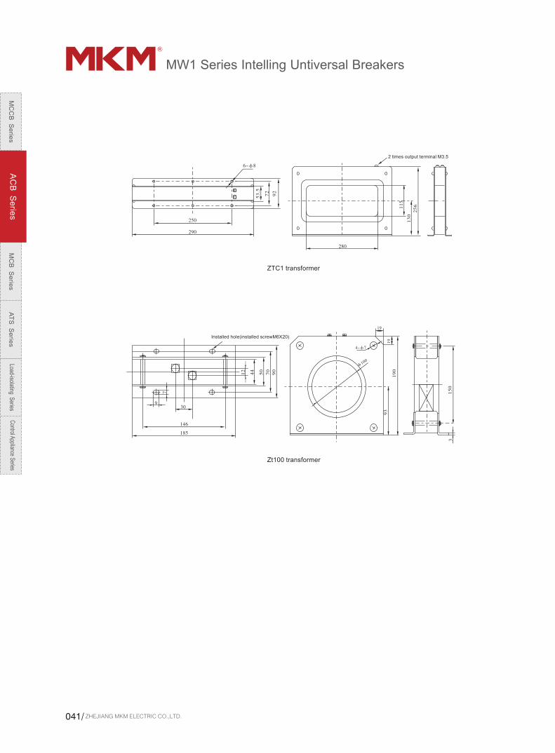
ZTC1 transformer
Zt100 transformer
2 times output terminal M3.5
Installed hole(installed screwM6X20)
ZHEJIANG MKM ELECTRIC CO.,LTD.041/
MC
CB
Se
ries
AC
B S
erie
sM
CB
Se
ries
AT
S S
erie
sLoad-isolating S
eriesC
ontrol Appliance Series
MW1 Series Intelling Untiversal Breakers
MC
CB
S
eri
es
AC
B S
eri
es
MC
B S
eri
es
AT
S S
eri
es
Load
-isol
atin
g S
erie
sC
ontro
l App
lianc
e Se
ries
www.mkm-electric.com /042