my settings • mis propias configuraciones • meine
TRANSCRIPT

My settings • Mis propias configuraciones • Meine Soundeinstellungen • Mes réglages •
AV
T15
0X/A
VT15
0HX
,A
VT27
5XA
VT15
0X/A
VT15
0HX
,A
VT27
5XA
VT15
0X/A
VT15
0HX
,A
VT27
5XA
VT15
0X/A
VT15
0HX
,A
VT27
5X
AdvancedValvestateTechnology
AVT150X, AVT150HX & AVT275XOwners Manual
Marshall Amplification plcDenbigh Road, Bletchley, Milton Keynes, MK1 1DQ, England.
Tel : +44 (0)1908 375411 Fax : +44 (0)1908 376118
www.marshallamps.com
Whilst the information contained herein is correct at the time of publication, due to our policy of constant improvement and development, Marshall Amplification plc reserve the right to alter specifications without prior notice.
BOOK-00083-00 / 9 / 05

From Jim Marshall
I would like to thank you personally for selecting oneof our Valvestate AVT amplifiers.
Ever since its initial launch in the early 1990’s, theoriginal Marshall Valvestate technology receivedworldwide acclaim and set a new standard in affordablequality amplification. However, my dedicated team ofdesigners are constantly looking for methods to make ouramplifiers sound even better. As they are all guitar playersthemselves this process has become a passion within thedesign department.
As the name Advanced Valvestate Technology (AVT) suggests,your new amplifier benefits from their research and utilises theirlatest circuit innovations, all of which are totally unique toMarshall. By emulating the feel and response of an all-valveamplifier even more closely, the AVT range perform brilliantlyand represent yet another major step forward in guitar soundtechnology.
I suggest that you read this manual thoroughly before operatingyour new amplifier and keep it in a safe place for futurereference. This will help you to derive maximum enjoyment fromour Advanced Valvestate Technology.
Wishing you every success.
Yours Sincerely,
EN
GLIS
H
1

2 3
What is AVT?Advanced Valvestate Technology, or AVT for short, is a major step forward in hybrid amplifier designwhich is exclusive to our Advanced Valvestate Series of amplifiers. It has evolved from the original,critically acclaimed Marshall Valvestate technology, but is improved so that it emulates even moreclosely the feel and response of the classic Marshall all-valve power stage...without using valves.
It is not only the power stage that has been significantly improved in the series either. Much carefulattention to detail and many hours of development have also gone into the preamp section too. As aresult, each AVT channel offers the widest possible range of control and shape to your sound, with anECC83 (a.k.a.12AX7) preamp valve adding to the all-important tone and feel of these latest Marshallcreations.
Valve Drive PreampAs just stated, each amp in the range boasts a preamp stage equipped with an ECC83 Dual Triodevalve. Drawing on our vast experience in this field, we have gone to great lengths to ensure that thisprecious device delivers maximum sonic benefit at all settings and volume levels. As a result, theclean sounds ring with the ‘bell-like’ harmonics that only a valve preamp can deliver and the break-upis never harsh or unnatural sounding. Whenever an AVT Overdrive channel is selected the ECC83’sdual triode is saturated to its limit, providing the dynamics and feel worthy of a place in the Marshallhall of fame.
Power Amp DeliveryThe same sort of toneful care and attention was also focused on the all-important power stages of theAVT series too. Our goal was to ensure that each one would create the warm, musical feel and 3-dimensional sounds that have made our all-valve power amps world renowned. In addition, these AVTproducts were designed to deliver the goods in the often hostile and unpredictable environment of thelive performance stage - which is why all the AVT power amps, from the AVT50X upwards, are fancooled for optimum reliability.
'Extended Bass Response' LoudspeakersKnowing how important the relationship between the amplifier and speaker is, this is another areawhere we spent a great deal of time and effort when developing the AVT Series. By working extremelyclosely with our long-term colleagues at Celestion Loudspeakers, we have successfully developed arange of speakers which, through radical design, re-define the state-of-the-art in rock guitarreproduction. In a nutshell, they allow the compact closed back cabinets used in the AVT range, tomaintain the bottom end delivery normally only associated with a full 4 x12 cabinet set-up.
DFX OnboardAt Marshall our aim is to create products that offer our fellow guitarists true inspiration in the practiceand performance of their art. When integrating DFX (Digital Effects) into the tonal topology of AVT, thegreatest care was taken to ensure that the highest level of signal integrity was maintained. Throughcareful shaping and mixing of the ‘wet’ (processed) and ‘dry’ (unprocessed) signals, we have ensuredthat the onboard effects enhance your tone while adding none of the nasty, artificial ‘grain’ oftenassociated with DFX. Different effect types can be assigned to the Clean and Overdrive channels andcan, of course, be turned on and off via the sturdy 6-way LED foot controller supplied with your amp.
I. The Preamp SectionYour AVT amp boasts no fewer than fourchannels: Acoustic Simulator, Clean, Overdrive1 and Overdrive 2. The preamp section is wherethe gain, tone and relative volume of these fourchannels is determined.
1. Input Jack SocketThis is where you plug your guitar into the amp.You must always use a screened (shielded)guitar cable and never use an unscreened(unshielded) speaker cable. Also, this cableshould be one of good quality. If you are in anydoubt regarding this, your Marshall dealer will bemore than happy to help and advise you.
2. Acoustic Sim. Channel Selector SwitchAllows selection of the Acoustic Simulatorchannel via the front panel.
3. Top ControlThis control takes the channel’s sound from amellow, acoustic tone (similar to a microphoneplaced towards the neck of the instrument) allthe way to a bright, piezo-like acoustic soundand all points in-between.
Note: The amp’s Master Presence control (21)affords you further adjustment of the high end.
4. Body SwitchThis changes the ‘body resonance’ simulation ofthe channel from that of a regular sized, steel-string acoustic (switch ‘out’) to that of a largebodied, ‘Jumbo’ acoustic (switch ‘in’).
5. Volume ControlThis dictates how loud the Acoustic SimulatorChannel will be.
6. Clean Channel Selector SwitchThis allows selection of the Clean channel viathe front panel.
7. Clean Channel Gain ControlThis rotary control regulates the drive into thetwo cascaded valve stages of the preamp.Lower settings will give you a wide range of welldefined, warm clean tones.
At higher Gain settings you will pass throughnatural, valve-induced compression and into anincreased level of desirable ‘break-up’ (a.k.a.‘crunch’) which is perfect for subtly overdrivenblues/rock.
8. Bright SwitchMost of the Gain controls in classic Marshallamps have been fitted with what is known as a‘treble bleed capacitor’. This device allows extrahigh frequencies to be ‘bled’ through to the drivesection when the Gain control is at low settings.Engaging the Bright Switch will ‘bleed’ extra highfrequencies into the drive stage of the Cleanchannel, giving you a bright, clean tone perfectfor many styles, including funk and country.The higher the Gain control is set, the less effectthe ‘treble bleed capacitor’ has. As a result, atmaximum Gain settings, the bright switch willhave no audible effect at all.
9. Clean Volume ControlAs its name suggests, this control determinesthe volume of the clean channel. The actualsetting you choose will be dependent on howloud you want the channel to be, and also onthe type of sound you have selected on the pre-amp. Due to the remarkable realism of ourAdvanced Valvestate Technology, once theVolume control is turned-up past a certain pointthe preamp will start to push the power ampsection into creating its own, desirable distortion- just like an all-valve Marshall amp. When thisoccurs, the AVT’s power amp will start to addmusical harmonics, compression and ‘break-up’into your sound.
Note: As each channel has its own volumecontrol, you can easily balance the levels of allfour channels as you so desire. Once set to yoursatisfaction, these controls can be left alone andyou can use the amp’s Master Volume knob (20)to set your overall volume level.
10. Clean Tone ControlsThe Clean channel is equipped with rotary Bass,Middle, and Treble controls. These three passiveEQ controls are designed to achieve maximumtonal variation from your AVT amplifier and, justlike the tone controls on our famous all-valveamps, are highly inter-dependent on each other.As a result, the way each one functions dependson the exact position of the other two controls.This is especially true of the Bass and Treblecontrols in relation to the Middle control. As youwill discover, the lower the Middle control is set,the more ‘reactive’ the others become.
As tone is very much down to personal taste,experimentation and experience is probably thebest way of learning how these three controls
AVT150X & AVT150HX Front Panel FeaturesIntroduction
EN
GLIS
HEN
GLIS
H

4 5
will affect your sound. To offer you someguidance, suggested settings are shown later onin this manual.
Points to remember are:When selecting a sound on any amp:a) The tone and output level coming out of eachguitar is as widely variable as guitarsthemselves. Remember, guitars and alsopickups are not designed (nor intended) to beequal. Therefore, amp settings will vary to suitboth your guitar and your playing style, and bynecessity, are at your discretion.
b) The tone of your sound is also dependent onthe way you set-up the Volume, Gain and Tonecontrols of your amp. Taking the time to adjustthem to taste will further enhance the sonictextures of your AVT. As is true of all the bestthings in life, it is worth investing some timeplaying around until you find the desired sweetspot!
Note: The amp’s Master Presence control (21)affords you further adjustment of the high end.
11. OD1 Channel Select SwitchPressing this front panel switch selects theOverdrive 1 (OD1) channel of your AVT.
12. OD1 Gain ControlThis rotary control can be best described as the‘sonic brain’ of the OD1 channel. Lower Gainsettings will produce well-defined, naturalsounding overdrives which have a nice ‘cut,’making them perfect for funky, blues rock.Higher gain settings will see the sound start toget more ‘rounded’ as the AVT’s pre-amp valveis pushed into saturation.
13. OD1 Scoop SwitchFine tuned to create the most awesome mid‘scoop’ imaginable, OD1's Scoop circuitry is morethan just a pre-set middle control. Instead itactually reconfigures the whole post-EQ voicingof the channel - from low to high. Because of this,even though the resulting ‘scooped’ sound thatoccurs when the switch is activated (pushed ‘in’)is totally extreme, the channel's overall tone stillremains tight and focused.
14. OD1 Volume ControlAs its name suggests, this control determinesthe volume of the OD1 channel. The actualsetting you choose will be dependent on howloud you want the channel to be, and also onthe type of sound you have selected on the pre-
amp (i.e. high Gain settings will generate muchmore preamp output level than lower, cleanersounding Gain settings).
Due to the remarkable realism of our AdvancedValvestate Technology, once the Volume controlis turned-up past a certain point, the preamp willstart to push the power amp section intocreating its own, desirable distortion - just likean all-valve Marshall amp. When this occurs, theAVT's power amp will start to add musicalharmonics, compression and desirable ‘break-up’ to your sound.
As previously stated, each channel has its ownvolume control so you can easily balance thelevels of all four channels. Once set to yoursatisfaction, these controls can be left alone andyou can use the amp’s Master Volume knob(20) to set your overall volume level to best suiteach playing situation and venue.
15. OD2 Channel Select SwitchThis selects the Overdrive (OD2) channel ofyour amp.
16. OD2 Gain ControlCranking the OD2 Gain control will unleash themost extreme gain levels ever found on aMarshall Valvestate amplifier. The highersettings of the OD2 gain control can be likenedto driving the front-end of an already ragingMarshall valve amp with a high gain, overdrivestomp box. If you've already experienced thetonal pleasure of ‘front ending’ a Marshall valveamplifier in this way, you will appreciate theenergy and dynamics of this type of set-up!Turning the OD2 Gain control clockwise will seemore of the already smouldering signal beingsweetly compressed and ‘rounded’ by theunique characteristic of the AVT's Valve Drivestage as it is driven over the top into totalsaturation. This channel can also be as nastyand ‘in-yer-face’ as you would like. Engaging theOD2 ‘Scoop’ button (17) will take this channelonto a new level of cranium crushing crunch,perfect for modern (a.k.a. ‘nu’) metal.
17. OD2 Scoop SwitchAs is true of the OD1 Scoop, this circuit acts likean advanced, pre-set contour control that notonly ‘scoops-out’ the mids but also shapes thehighs and lows for a tight, focused sound.Engaging OD2’s Scoop Switch loads you upwith a ‘bottom heavy’ sound perfect for the de-tuned, high-gain aggression favoured by manymodern acts.
18. OD2 Volume ControlThis control regulates the drive of the OD2channel into the power stage of the amplifier,hence controlling its output volume. You will findthat the louder you go, the looser the bottomend of your sound will become. Having said this,the closed-back cabinet design of your AVT issuch that it will deliver tight, well-defined lowend at much higher volumes than any other‘hybrid’ amplifier known to man.
19. Overdrive Tone ControlsYour AVT is equipped with rotary Bass, Middle,and Treble EQ controls which are sharedbetween the two Overdrive Channels, OD1 andOD2. This EQ section boasts a tone circuitidentical to the one used in legendary Marshallvalve amplifiers such as the 100 Watt ‘Plexi’ andthe JCM800 2203, making it a foundation stonefor that instantly recognisable andunsurpassable ‘Marshall Sound’. As was thecase with the Clean channel’s EQ network,these controls are interactive and, as a result,allow endless tonal possibilities.
Note: Remember that in addition to these threecontrols, further tonal adjustment is alsoafforded by the Scoop button (17) and also theMaster Presence control which is explained later(21).
II. The Master Section
These controls adjust the power amp section ofyour AVT and determine the overall Volume andPresence of the amplifier.
20. Master VolumeOnce you have set the relative volumes of yourAVT's channels, this control governs the overallvolume of the amplifier.
21. Master PresenceA feature normally only found on expensivevalve amplifiers, the Presence control affordsyou increased high frequency control by alteringthe power amplifier’s feedback. Increasing thePresence control will emphasise high-end ‘fizz’in overdriven tones and top-end ‘sparkle’ inclean sounds.
III. FX Section
A. Parallel FX LoopYour AVT boasts a rear-panel mounted ParallelFX loop for use with external effects devices.This FX loop is Mono in the case of theAVT150X and AVT150HX and Stereo (MonoSend, L & R Returns) in the case of theAVT275X (see ‘Rear Panel Features’ Section formore details).
22. FX Loop Mix Controls (Clean &Overdrive)When an effects unit is hooked-up to theaforementioned FX loop, the top control adjuststhe FX Mix for the two OD channels and turningit clockwise increases the amount of effect youhear - from ‘dry’ (0) to ‘wet’ (10). The bottom FXMix control does the exact same thing for theAcoustic Simulator and Clean channels.
Please note that the FX mix on your externalprocessor should be set to maximum (i.e. ‘wet’).
B. Internal Digital FXAs mentioned in the introduction of this manual,the AVT150X, AVT150HX and AVT275X eachfeature two separate DFX (Digital Effects)sections - the upper DFX section is for the twoOverdrive channels, OD1 and OD2, and thelower section is for the Clean & AcousticSimulator Channels. Each DFX section boasts16 on-board effects and three controls - DFXMix, Adjust and Program.
We chose the particular effects algorithms togive you a comprehensive palette of naturalsounding options. When developing the DFXsection, our aim was to enhance the overallsound of the amplifier and, most importantly,allow the effects to work with you instead ofmasking your all-important tone underneathlayers of artificial sounding digital signalprocessing.
EN
GLIS
HEN
GLIS
H

6 7
The first 10 programs offered are all Reverbs. Reverberation effects recreate the natural echoreflections found in physical environments such as halls and rooms or, in the case of plate reverbs, amechanically vibrating metal plate. These echoes are extremely complex in nature and are, therefore,notoriously difficult to recreate. In developing these 10 programs we've gone to great lengths toensure that none of the harsh digital ‘graininess’ normally associated with some digital reverbs ispresent.
Below is a brief description of each of the 16 DFX programs available:
1 Hall A: this is a large, bright sounding, concert hall. “Wembley Arena, are you ready to rock!?”
2 Hall B: warmer sounding than Hall A, this program is perfect for adding depth and character to clean and acoustic tones.
3 Hall C: a medium sized hall with 12ms of delay before the reverb starts.
4 Room 1: a hardwood studio with lots of early reflections. Perfect for acoustic type sounds.
5 Room 2: perfect for adding some subtle ambience.
6 Room 3: warmer sounding than Room 1, perfect for clean or acoustic work.
7 Plate 1: a bright, transparent plate sound ideal for lead work.
8 Plate 2: warmer sounding than Plate 1, this program is great for adding sustain, especially on clean and acoustic tunes.
9 Plate 3: an accurate emulation of a vintage tube plate reverb. As this program has very little low end it is great for adding ‘cut’.
10 Gated Reverb: by ‘chopping-off’ the end of the reverb’s decay ‘tail’ via a Noise Gate, this program is great for spicing-up chord stabs without cluttering up your sound.
11 Chorus: splitting the signal and then mixing the dry signal with a detuned version creates this popular effect. To add to the subtle ‘widening’ this creates, the detuned signal is modulated by an LFO (Low Frequency Oscillator) which causes the detuning to vary. The result is a subtle, lush sound that is equally effective on both clean and dirty tones.
12 Flange: similar to chorus but much more ‘jet’ like in nature.
13 Delay: this creates an echo repeat of the original signal. The delay time is adjustable in 10 millisecond (ms) increments and can be set to be as long as 1270ms which is well over 1 second.
14 Chorus/Room: as the name suggests, this combines Chorus and a large room Reverb.
15 Chorus/Delay/Room: if program 14 isn't dramatic enough for you then this is definitely the one for you, as it adds Delay to the Chorus & Reverb mix!
16 Modulation: this effect is similar to the chorus effect but is less subtle and can be used to create rotary speaker-like effects.
23. DFX Mix Controls (Clean FX &Overdrive FX)These determine the level of the internal effectsselected by the pair of Program controls (25).The top DFX Mix control works on the two ODchannels while the bottom one works on theAcoustic Simulator and Clean channels. Ingeneral you will find that the modulation effects(e.g. Chorus, Flange) require more level thanthe reverbs and delays. As always, let your earsdecide what is right!
24. Adjust Controls (Clean FX &Overdrive FX)For each of the 16 selectable DFX a particularparameter is adjustable. For example, when aReverb is chosen, the decay (how long thereverb will be heard before it fades away) isadjustable via this control. The ‘Program/Adjust’table (26) on the front panel of your amp listswhat the Adjust control does for each of the 16programs. As was the case with the DFX Mixcontrols, the top Adjust control works for the twoOD channels and the bottom one for the Clean& Acoustic Simulator channels.
25. Program (Clean FX & Overdrive FX)These select each one of the 16 on board digitaleffects - the top Program control works on thetwo OD channels and the bottom control worksfor the Clean and Acoustic Simulator Channels.The DFX available include single effects such asReverb (9 types), Delay or Chorus and alsomulti-FX such as Chorus/Delay/Room. To addfurther to the flexibility of these two DFXsections, they can be switched on and off viathe sturdy, LED foot-controller which comessupplied with each amp.
26. Digital FX Program/Adjust TableThis lists the 16 programs selectable via theProgram control (25) and also indicates whichparameter the Adjust control (24) modifies foreach one. For added convenience, this table isshown below.
27. Power SwitchWait for it...yes, this switches the amp on andoff! When the amp is on the power switch isilluminated and vice-versa. Advanced poweramplifier muting circuitry provides anti-thumpprotection on power up and down.
Important Note: As is the case with an all-valveamplifier, there will be no signal heard until theamp's ECC83 preamp valve warms-up andstarts to pass signal. This can take up to 15seconds so don't panic!
EN
GLIS
HEN
GLIS
H

8 9
1. Mains Input ConnectorYour AVT is provided with a detachable mains(power) lead which is connected here. Thespecific mains input voltage rating that youramplifier has been built for is shown on the backpanel. Before connecting for the first time,please ensure that your electricity supply iscompatible with your amplifier. If you have anydoubt, please seek advice from a qualifiedtechnician. Your Marshall dealer will help in thisrespect.
2. Loudspeaker Jack Socketsa) AVT150XThere are two speaker jacksockets on theAVT150X. The one marked Internal (8 Ohm) iswhere the output of the AVT power amplifier isconnected to its internal 8 Ohm Celestionloudspeaker.When an extension speaker is connected to theother output (marked Extension) the full powerof the 150W power amplifier is unleashed.Please note that only an extension cabinet ratedat 8 Ohms should be used. This will provide a parallel load with the InternalSpeaker of 4 Ohms minimum.
b) AVT150HXThe AVT150HX has two loudspeaker outputs.The one marked ‘Extension 8Ω’ is forconnection to a single 8 Ohm cabinet. Theoutput marked ‘Extension 8/4Ω’ can either beused for connection to a second 8 Ohm speakercabinet, or to drive a single 4 Ohm cabinet.
WARNING:Always provide the AVT with a load equal to, orgreater than, 4 Ohms. Note: Two 8Ω cabinets connected in parallel = 4Ω
3. FootswitchFor connection of the supplied Stage FootController (PEDL-10031). This sturdy 6-wayMarshall footswitch allows instant selection ofthe 4 channels, plus the two DFX modes. It alsofeatures LEDs to indicate status.
4. HeadphonesThe headphones output is fully emulated usingan improved version of the circuitry found on theindustry standard JMP-1. Turning the MasterVolume (20) to zero will provide silent practice.
5. Emulated Line OutputThis jack socket carries a specially treatedoutput signal from your AVT that accuratelyemulates the sonic signature of a Marshall 4x12cabinet. This unerringly accurate emulationcircuitry is Marshall's most advanced to dateand was developed via countless hours oftechnical research, playing, listening and fine-tuning. This output can be used in both liveperformance and recording situations to achieveauthentic guitar amp tones, without having touse a microphone. Turn down the MasterVolume (20) for silent recording.
FX LoopAs already mentioned, the AVT150X andAVT150HX both boast a Mono Parallel FX loopfor connection with external effects units. Inaddition to the FX Mix controls on the frontpanel (see ‘Front Panel Features’, point 22) thisFX loop comprises of an FX Send jack, an FXReturn jack and an FX level control button.
6. FX ReturnFor connection to the output of your externaleffects device.
7. FX LevelThis should be set to match the level of theprocessor being used (generally -10dB for astomp box, +4dB for a professional, rack unit).
8. FX SendFor connection to the input of the externaldevice being used.
* FX Loop Hints:a) Always use high quality, shielded patchcables.
b) If the processor being used has an input levelcontrol, ensure it is set correctly.
c) Time based effects (delays & reverbs) andmodulation effects (chorus, flange, phase, etc.)are ideal for use in a Parallel FX loop.
d) Certain stomp box effects such as Wah,distortion, overdrive and fuzz were designedspecifically for use in front of the amp and soundbest when used that way. This said, tonal beautyis in the ears of the beholder so, if such a pedalsounds great to you when used in an FX loopthen go for it! Sometimes, there are no rules...
!!
AVT150X & AVT150HX Rear Panel Features AVT275X Rear Panel Features
1. Mains Input ConnectorYour AVT is provided with a detachable mains(power) lead which is connected here. Thespecific mains input voltage rating that youramplifier has been built for is shown on the backpanel. Before connecting for the first time, pleaseensure that your electricity supply is compatiblewith your amplifier. If you have any doubt, pleaseseek advice from a qualified person. YourMarshall dealer will help in this respect.
2. Loudspeaker Jack SocketsThese connect the internal loudspeakers to thestereo power amplifier outputs.
WARNING:Always provide both with a load equal to, orgreater than 8 Ohms.
3. Footswitch For connection of the supplied stage footcontroller (PEDL-10031). This sturdy 6 way,Marshall footswitch allows instant selection ofthe 4 channels, plus the two DFX modes. It alsofeatures LEDs to indicate status.
4. HeadphonesThe headphones output is fully emulated usingan improved version of the circuitry found on theindustry standard JMP-1. Turning the MasterVolume (20) to zero will provide silent practice.
5. Emulated Line Outputs (L, R)This pair of stereo jack sockets carries aspecially treated output signal from your AVTthat accurately emulates the sonic signature of aMarshall stereo 4x12 cabinet. This unerringlyaccurate emulation circuitry is Marshall's mostadvanced to date and was developed viacountless hours of technical research, playing,listening and fine-tuning. This output can beused in both live performance and recordingsituations to achieve authentic guitar amp tones,without having to use a microphone. Turn downthe Master Volume (20) for silent recording.
FX LoopAs previously mentioned, the AVT275X boasts aParallel FX loop for connection with externaleffects units. In addition to the FX Mix controlson the front panel (see ‘Front Panel Features’,point 22) this FX loop comprises of an FX Sendjack, two FX Return jacks, Left & Right, and anFX level control button.
6. FX Return Left & RightFor connection with the stereo output of yourexternal effects device - left goes to left and,wait for it, right goes to right.
Note: when using a mono output device use theRight (R) FX return as indicated.
7. FX LevelThis should be set to match the level of the
processor being used (-10dB for a stomp box,+4dB for a professional, rack unit).
8. FX SendFor connection with the input of the externaldevice being used.
* FX Loop Hints:a) Always use high quality, shielded patchcables.
b) If the processor being used has an input levelcontrol, ensure it is set correctly.
c) Time based effects (delays & reverbs) andmodulation effects (chorus, flange, phase, etc.)are ideal for use in a Parallel FX loop.
d) Certain stomp box effects such as Wah,distortion, overdrive and fuzz were designedspecifically for use in front of the amp and soundbest when used that way. This said, tonal beautyis in the ears of the beholder so, if such a pedalsounds great to you when used in an FX loopthen go for it! Sometimes, there are no rules...
!!
EN
GLIS
HEN
GLIS
H
Follow all instructions and heed all warnings KEEP THESE INSTRUCTIONS !

150
1
150
1
150
1
1110
Suggested Settings AVT150X / AVT150HX & AVT275X Suggested Settings
On all the following suggested settings you will immediately notice how rich and authentic the soundsare. As you will hear, even on clean settings Advanced Valvestate Technology adds those subtleharmonics and that desirable compression which only a classic all-valve amp can normally deliver.
Bright Piezo Acoustic‘Bright Piezo Acoustic’ closely simulates the sound of a piezo equipped semi-acoustic. This settingworks best with the neck pickup. Adding some Chorus/Room effect (Program 14) will give a 12 stringsound for folky strumming.
Mellow JumboEngaging the Body Switch (4) and decreasing the Top control (3) will give a really full ‘JumboAcoustic’ type sound. Add some Hall Reverb (Program 2) for atmospheric acoustic lead work.
Funky CleanA really bright clean which still maintains mid definition. This is best used in conjunction with a single-coil neck pick-up or the neck/bridge combination on a humbucker equipped guitar. Keeping the Gaincontrol low ensures a clean preamp signal and also helps feed extra treble through to the poweramplifier for additional brightness and cut.
Blues CleanHere the preamp Gain is increased and what you start to hear is pure, harmonically rich break-up andcompression from the internal Marshall ECC83 preamp valve. Again the neck pick-up on a single coilguitar or the neck/ bridge combination on a humbucker-loaded guitar will deliver the warmest tones.
Jazz CleanA warm rounded clean ideal for ‘comping’ and walking bass progressions.
Brit CrunchHere the advantage of the separate Gain and Volume controls really comes into play. Notice how theGain is quite low but the Volume is quite high. This is the way the old Marshall crunch sounds of thelate 60’s and 70’s were created - namely by keeping the preamp pretty clean and creating the desireddistortion by driving the power stage hard. With such a setting, when you back off the guitar's volumeor pick lighter, you will feel and hear how the rich, clear tone of the clean sound remains.
Funky OverdriveFor those who wish to get lost in a purple haze, back off OD1's Gain to give extra definition anddynamics.
MV CrunchThis crunch is reminiscent of the first Marshall Master Volume amplifiers of the much heraldedJCM800 series. The Valve Drive Preamp is driven into mild saturation, creating a big, open overdriveusing the bridge position pick-up, whether single-coil or humbucker.
Screaming LeadHere the Gain is cranked to the max and the mids are brought up to fatten the tone of the singlenotes. With these settings the rich, natural harmonic overtones that the valve introduces will be veryapparent. Best with the bridge pickup.
Heavy, Modern CrunchCutting the Mids while heavily boosting the Gain, Treble and Bass gives an aggressive, modern ‘tear-yer-face-off’, scooped sound. The bridge humbucker is the one to use here if you truly wanna ride thelightning...definitely not for the faint-hearted!
EN
GLIS
HEN
GLIS
H
150
1
Brig
ht P
iezo A
cou
sticM
ellow
Jum
bo
Fu
nky C
leanB
lues C
leanJazz C
lean
Select
Select
Select
Select
150
1
Select Select

150
1
2
3456
7
8
9
10
1112 13 14
15
16
1
2
3456
7
8
9
10
1112 13 14
15
16
150
1
2
3456
7
8
9
10
1112 13 14
15
16
1
2
3456
7
8
9
10
1112 13 14
15
16
150
1
2
3456
7
8
9
10
1112 13 14
15
16
1
2
3456
7
8
9
10
1112 13 14
15
16
150
1
2
3456
7
8
9
10
1112 13 14
15
16
1
2
3456
7
8
9
10
1112 13 14
15
16
150
1
2
3456
7
8
9
10
1112 13 14
15
16
1
2
3456
7
8
9
10
1112 13 14
15
16
1312
EN
GLIS
H
Bri
t C
run
chF
un
ky O
verd
rive
MV
Cru
nch
Scr
eam
ing
Lea
d
Select
Select
Select
Select
Select
Hea
vy M
od
ern
Cru
nch
AVT150X / AVT150HX & AVT275X Suggested Settings
De Jim Marshall
Quiero, ante todo, agradecerte personalmente porhaber elegido uno de nuestros amplificadoresValvestate AVT.
Desde su lanzamiento inicial a principios de los 90, latecnología original Marshall Valvestate fue aclamadamundialmente y se estableció como referencia enamplificación asequible de primera categoría. De todas formas,mi equipo de diseñadores está constantemente investigando parahacer que nuestros amplificadores suenen aún mejor. Puesto quetodos ellos son guitarristas, este proceso de búsqueda es unaauténtica pasión en el departamento de investigación y desarrollo.
Como su propio nombre (Advanced Valvestate Technology oTecnología Valvestate Avanzada) sugiere, tu nuevo amplificadordisfruta de esta entusiasta investigación y cuenta con la másnovedosa circuitería, absolutamente exclusiva de Marshall.Simulando la respuesta y “sensación” de un amplificador totalmentede válvulas, la nueva gama AVT tiene un comportamientoexcepcional y constituye un enorme paso adelante en la tecnologíadel sonido de guitarra.
Te sugiero que leas este manual completamente antes de comenzara utilizar tu nuevo ampli y que lo conserves para futuras consultas.Esto te ayudará a obtener el máximo rendimiento y disfrute de laTecnología Valvestate Avanzada.
Te deseo mucho éxito.
Sinceramente,
ESPA
ÑO
L
150
1
2
3456
7
8
9
10
1112 13 14
15
16
1
2
3456
7
8
9
10
1112 13 14
15
16
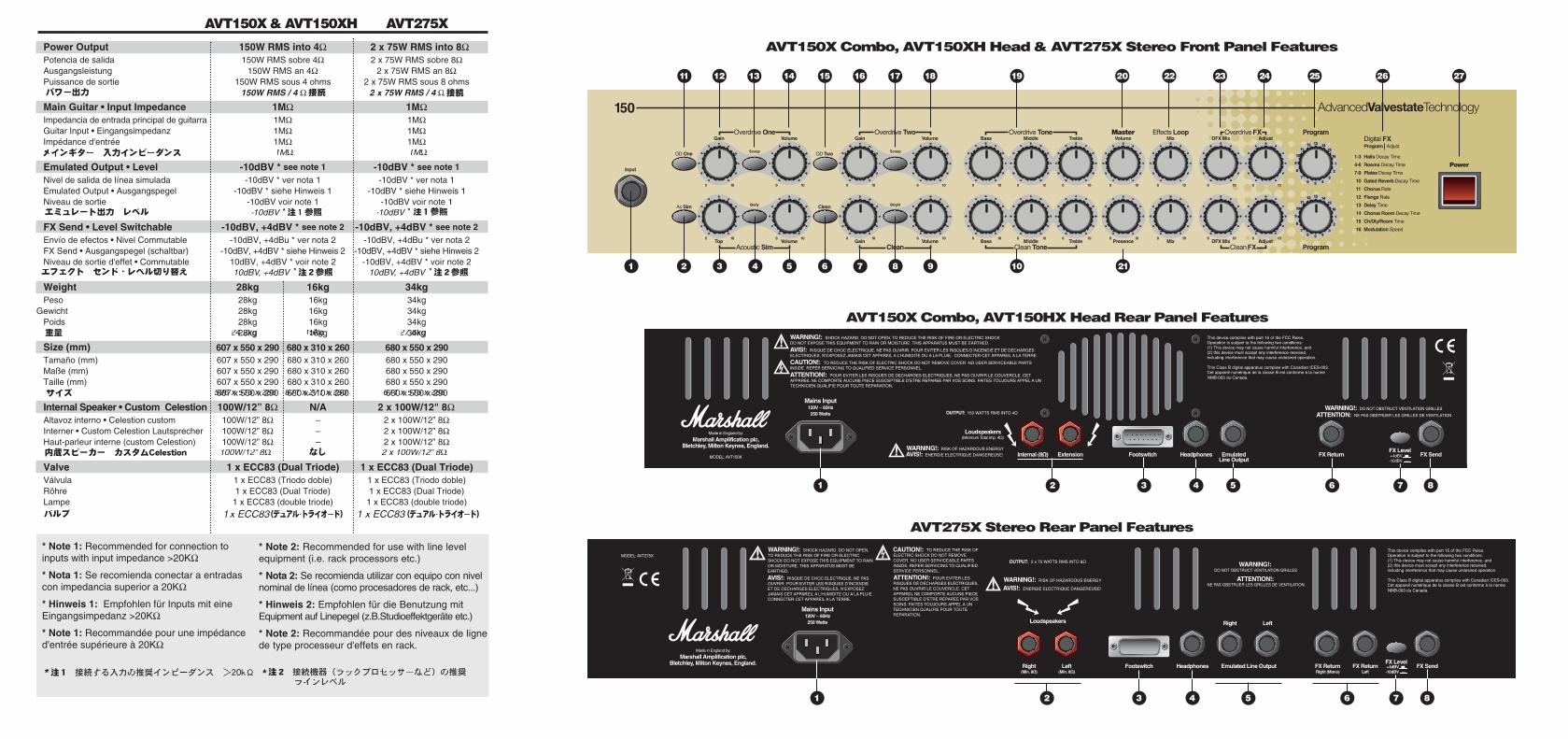
11 12 13 14 15 16 17 18 19 20 22 23 24 25 26 27
AVT150X Combo, AVT150XH Head & AVT275X Stereo Front Panel Features
1 2 3 54 7 9 10 2186
AVT150X Combo, AVT150HX Head Rear Panel Features
1 2 3 4 6 7 85
1 2 3 4 6 7 85
AVT275X Stereo Rear Panel Features
Welcome from Jim Marshall p1Introduction p2AVT150X, AVT150HX & AVT275X p3Front Panel Features
Technical Specification Especificaciones técnicasTechnische DatenCaractéristiques techniques
AVT150X/AVT150HX Rear Panel Features p8AVT275X Rear Panel Features p9Suggested Settings p10
Bienvenida de Jim Marshall p13Introducción p14AVT150X/AVT150HX y AVT275X p15Funciones del panel frontal
AVT150X y AVT150HX p21Funciones del panel traseroAVT275X Panel Trasero p22Configuraciones que sugerimos p24
Ein Gruß von Jim Marshall S. 27Einleitung S. 28AVT150X/AVT150HX & AVT275X S. 29Features auf der Frontplatte
AVT150X & AVT150HX S. 34Features auf der RückseiteAVT275X Rückseite S. 36Soundvorschläge S. 37
De la part de Jim Marshall p40Introduction p41Fonctions de face avant: p42AVT150X/AVT150HX et AVT275X
Faces arrières des modèles p47AVT150X et AVT150HX AVT275X Face arrière p48Exemples de réglages p49
EN
GLIS
HESPA
ÑO
LD
EU
TSC
HFR
AN
ÇA
ISJA
PA
NESE
Page 81
CONTENTS
CONTENIDOS
INHALT
SOMMAIRE
Power Output 150W RMS into 4Ω 2 x 75W RMS into 8ΩPotencia de salida 150W RMS sobre 4Ω 2 x 75W RMS sobre 8ΩAusgangsleistung 150W RMS an 4Ω 2 x 75W RMS an 8ΩPuissance de sortie 150W RMS sous 4 ohms 2 x 75W RMS sous 8 ohms
Main Guitar • Input Impedance 1MΩ 1MΩImpedancia de entrada principal de guitarra 1MΩ 1MΩGuitar Input • Eingangsimpedanz 1MΩ 1MΩImpédance d'entrée 1MΩ 1MΩ
Emulated Output • Level -10dBV * see note 1 -10dBV * see note 1
Nivel de salida de línea simulada -10dBV * ver nota 1 -10dBV * ver nota 1 Emulated Output • Ausgangspegel -10dBV * siehe Hinweis 1 -10dBV * siehe Hinweis 1Niveau de sortie -10dBV voir note 1 -10dBV voir note 1
FX Send • Level Switchable -10dBV, +4dBV * see note 2 -10dBV, +4dBV * see note 2
Envío de efectos • Nivel Commutable -10dBV, +4dBu * ver nota 2 -10dBV, +4dBu * ver nota 2FX Send • Ausgangspegel (schaltbar) -10dBV, +4dBV * siehe Hinweis 2 -10dBV, +4dBV * siehe Hinweis 2Niveau de sortie d'effet • Commutable 10dBV, +4dBV * voir note 2 -10dBV, +4dBV * voir note 2
Weight 28kg 16kg 34kgPeso 28kg 16kg 34kg
Gewicht 28kg 16kg 34kgPoids 28kg 16kg 34kg
28kg 16kg 34kg
Size (mm) 607 x 550 x 290 680 x 310 x 260 680 x 550 x 290Tamaño (mm) 607 x 550 x 290 680 x 310 x 260 680 x 550 x 290Maße (mm) 607 x 550 x 290 680 x 310 x 260 680 x 550 x 290 Taille (mm) 607 x 550 x 290 680 x 310 x 260 680 x 550 x 290
607 x 550 x 290 680 x 310 x 260 680 x 550 x 290
Internal Speaker • Custom Celestion 100W/12” 8Ω N/A 2 x 100W/12" 8ΩAltavoz interno • Celestion custom 100W/12” 8Ω – 2 x 100W/12” 8ΩInterner • Custom Celestion Lautsprecher 100W/12” 8Ω – 2 x 100W/12” 8ΩHaut-parleur interne (custom Celestion) 100W/12” 8Ω – 2 x 100W/12” 8Ω
Valve 1 x ECC83 (Dual Triode) 1 x ECC83 (Dual Triode)Válvula 1 x ECC83 (Triodo doble) 1 x ECC83 (Triodo doble) Röhre 1 x ECC83 (Dual Triode) 1 x ECC83 (Dual Triode)Lampe 1 x ECC83 (double triode) 1 x ECC83 (double triode)
AVT150X & AVT150XH AVT275X
1MΩ 1MΩ
24.2kg 15kg 27.6kg
596 x 515 x 285 671 x 271 x 250 671 x 515 x 285
100W/12” 8Ω 2 x 100W/12” 8Ω
* Note 1: Recommended for connection toinputs with input impedance >20KΩ
* Nota 1: Se recomienda conectar a entradascon impedancia superior a 20KΩ
* Hinweis 1: Empfohlen für Inputs mit eineEingangsimpedanz >20KΩ
* Note 1: Recommandée pour une impédanced'entrée supérieure à 20KΩ
* Note 2: Recommended for use with line levelequipment (i.e. rack processors etc.)
* Nota 2: Se recomienda utilizar con equipo con nivelnominal de línea (como procesadores de rack, etc...)
* Hinweis 2: Empfohlen für die Benutzung mitEquipment auf Linepegel (z.B.Studioeffektgeräte etc.)
* Note 2: Recommandée pour des niveaux de lignede type processeur d'effets en rack.
* EUROPE ONLY - Note: This equipment has been tested and found to comply with therequirements of the EMC directive (Environments E1, E2 and E3 EN 55103-1/2) and the Low Voltagedirective in the E.U.
* EUROPE ONLY - Note: The Peak Inrush current for the AVT150X, AVT150HX & AVT275X is 32amps.
Note: This equipment has been tested and found to comply with the limits for a Class B digitaldevice, pursuant to part 15 of the FCC rules. These limits are designed to provide reasonableprotection against harmful interference in a residential installation. This equipment generates, usesand can radiate radio frequency energy and, if not installed and used in accordance with theinstructions, may cause harmful interference to radio communications. However, there is noguarantee that interference will not occur in a particular installation. If this equipment does causeharmful interference to radio or television reception, which can be determined by turning theequipment off and on, the user is encouraged to try to correct the interference by one or more of thefollowing measures: u Reorient or relocate the receiving antenna. u Increase the separation between the equipment and the receiver. u Connect the equipment into an outlet on a circuit different from that to which the receiver is
connected. u Consult the dealer or an experienced radio/TV technician for help.
* SÓLO PARA EUROPA - Nota: Este equipo ha sido examinado y se ha comprobado quecumple la normativa EMC (Apartados E1, E2 y E3 EN 55103-1/2) y la normativa de Baja Tensión dela U.E.
* SÓLO PARA EUROPA - Nota: La corriente de pico en el encendido del AVT150X, AVT150HX &AVT275X es de 32 amperios.
Nota: Este equipo ha sido examinado y calificado como aparato digital de Clase B, de acuerdo conla parte 15 de la normativa FCC. Esta calificación fue definida para garantizar una protecciónrazonable contra interferencias en una instalación doméstica. Este equipo genera, utiliza y puederadiar energía de radiofrecuencia y, si no se instala y utiliza de acuerdo con las instrucciones, puedeproducir interferencias indeseadas a las radiotransmisiones. De todas formas, no hay una garantíatotal de que no ocurran interferencias en ciertas instalaciones. Si este equipo produce interferenciasperjudiciales a la recepción en aparatos de radio o televisión, lo cual se puede deducir observando elefecto al encender y apagar el equipo, se sugiere al usuario que intente corregir estas interferenciassiguiendo una o varias de las siguientes medidas:u Reorientar o reubicar la antena receptora de la radio o televisión.u Aumentar la separación entre el equipo y el aparato receptor.u Conectar el equipo en un enchufe de un circuito de alimentación distinto de aquel al que va
conectado el receptor.u Consultar con el vendedor o con un técnico experto en radio y TV.
English
Español
* EUROPE UNIQUEMENT - Remarque: Ce matériel a été testé: il est conforme auxdirectives européennes EMC (Environnement E1, E2 et E3 EN 55103-1/2) et aux directives sur lesappareils basse tension.
* EUROPE UNIQUEMENT - Remarque: La consommation en crête du AVT150X, AVT150HX &AVT275X est de 32 ampères.
Note: Cet équipement a été testé et approuvé conforme aux normes fédérales sur les appareilsnumériques de Classe B selon le résolution fédérale américaine. Ces limites sont désignées pourfournir une protection raisonnable contre les interférence en installation résidentielle. Cet appareilgénère, utilise et peut émettre des fréquences radio et, en cas d’installation ou d’utilisation différentede ce qui est préconisé dans ce mode d’emploi, il peut entraver la bonne réception des équipementsde télévision ou radio avoisinants. Cependant, nous ne pouvons garantir l’absence d’interférencesselon l’application utilisée. Si cet appareil est source d’interférence (vérifiez en plaçant l’appareil sousou hors tension à plusieurs reprises), nous vous encourageons à appliquer l’une des mesuressuivantes:u Réorientez ou déplacez l’antenne de réception.u Augmentez la distance entre l’appareil et le récepteur.u Connectez le matériel sur une ligne secteur différente de celle du récepteur.u Consultez votre revendeur ou un spécialiste TV/Radio.
* GILT NUR FÜR EUROPA - Hinweis: Dieses Gerät entspricht den Anforderungen der EMCRichtlinien (Anlagen E1, E2 und E3 EN 55103-1/2) und den Anweisungen für Niederspannung derE.U und wurde entsprechend getestet.
* GILT NUR FÜR EUROPA - Hinweis: Die Stromspitze beim Einschalten liegt beim AVT150X,AVT150HX & AVT275X bei 32 Ampere.
Die entsprechenden Grenzwerte stellen einen ausreichenden Schutz vor störenden Interferenzenbeim Gebrauch im Wohnbereich sicher. Dieses Gerät generiert und arbeitet im Radiofrequenzbereichund kann eine entsprechende Strahlung aussenden. Wird das Gerät nicht entsprechend denBedienungsanweisungen benutzt, so kann es zu Störungen beim Empfang von Radio- oder TV-Signalen kommen. Es ist grundsätzlich nicht auszuschließen, daß es bei einigen Anwendungen zuderartigen Störungen kommen kann. Sollte dies einmal der Fall sein (zur Überprüfung sollte dasGerät an- und ausgeschaltet werden) so schlagen wir die folgenden Lösungsansätze vor:u Positioniere die Empfangsantenne anders.u Vergrössere den Abstand zwischen dem Verstärker und dem Empfangsgerät.u Benutze einen anderen Netzanschluß für beide Geräte.u Konsultiere einen Händler oder geschulten Radio-Fernsehtechniker.
Deutsch
Français
66 67