mylar_propiedades electricas
TRANSCRIPT

polyester filmMylar®
Product Information
Electrical Properties
Mylar® offers unique design capabilities to theelectrical industry due to the excellent balance ofits electrical properties with its chemical, thermal,and physical properties. Detailed descriptions ofthese latter properties are included in other avail-able bulletins. Table 1 is a summary of sometypical electrical properties; further details on theseand other electrical properties are included in theremaining pages of the bulletin.
Dielectric StrengthThe short-term dielectric strength test (ASTMD149) is primarily used to measure the quality of afilm. This test method allows considerable freedomin the choice of electrode size, environmentalconditions, etc. The following discussion of thesevariables is based on tests run with brass electrodesof the dimensions prescribed in ASTM D2305. Inlimited testing, stainless steel electrodes gaveresults similar to those obtained with the standardbrass electrodes. The data were obtained at afrequency of 60 Hz, using a 500 V/sec rate of rise,unless otherwise noted.
Film ThicknessAs with most materials, the AC Dielectric Strengthof Mylar® polyester film in V/mil decreases as filmthickness increases (see Figure 1). At 500 V/secrate of rise, corona occurs within a few seconds,and the film begins to melt before the actualbreakdown occurs. The greater the film thickness,the more the failure is due to melting and, thus, thelower the V/mil as thickness increases.
Electrode SizeDifferences in dielectric strength values may resultwhen comparing 1/4 in and 2 in diameter brasselectrodes. Because of the larger film area betweenthe electrodes, the potential for lower dielectricstrength values is greater with 2-in electrodes.
Figure 1. Dielectric Strength vs. Thickness(2 in Electrode in air at 25°C [77°F])
Thickness, mil
Die
lect
ric
Str
eng
th, V
/mil
40,000
30,000
10,000
8,000
6,000
4,000
3,000
2,000
1,0001 2 4 6 8 10 14 20/1 4 /1 2
20,000

2
Table 1Typical Electrical Properties of Mylar Polyester Film
Property Value Test Method
DC Dielectric Strength Typical Value for Mylar 92 EL/C*25°C (77°F) 11.0 kV/mil 1/4 in upper electrode
and flat plate lowerelectrode. 500 V/secrate of rise
Gauge and Type at 25°C (77°F) Minimum Values for Mylar C Film6C 0.225 kV Minimum average7C 0.300 kV voltage of 20 film-foil8C 0.320 kV capacitors, 0.5 µF each
10C 0.490 kV12C 0.650 kV14C 0.825 kV20C 1.500 kV24C 2.000 kV32C 3.100 kV 100 V/sec rate of rise40C 4.100 kV48C 4.900 kV75C 5.500 kV92C 6.000 kV
AC Dielectric Strength Typical Value for Mylar 92 EL/C*25°C (77°F) 7.0 kV/mil ASTM D149 and
ASTM D230560 Hz500 V/sec rate of rise
Gauge and Type at 25°C (77°F) Minimum Values for Mylar EL Film48EL 2.8 kV ASTM D149 and D2305,75EL 3.5 kV Minimum average92EL 4.0 kV voltage of 10 sheet
142EL 5.5 kV samples200EL 7.7 kV300EL 10.0 kV 60 Hz500EL 13.5 kV 500 V/sec rate of rise750EL 17.5 kV900EL 18.4 kV
1000EL 19.0 kV1400EL 20.0 kV
Dielectric Constant Typical Value for Mylar 92 EL/C*25°C (77°F)—60 Hz 3.3 ASTM D15025°C (77°F)—1 kHz 3.2525°C (77°F)—1 MHz 3.025°C (77°F)—1 GHz 2.8150°C (302°F)—60 Hz 3.7
Dissipation Factor Typical Value for Mylar 92 EL/C25°C (77°F)—60 Hz 0.0025 ASTM D15025°C (77°F)—1 kHz 0.005025°C (77°F)—1 MHz 0.01625°C (77°F)—1 GHz 0.008150°C (302°F)—60 Hz 0.004–269°C (–452°F)—1 kHz (in Helium) 0.0002
Volume Resistivity Typical Value for Mylar 92 EL/C25°C (77°F) 1018 ohm⋅cm ASTM D257 and D2305150°C (302°F) (Type C Film) 1013 ohm⋅cm
Surface Resistivity23°C (73°F)—30% RH 1016 ohm/sq23°C (73°F)—80% RH 1012 ohm/sq
Insulation Resistance35°C (95°F)—90% RH 1012 ohm
Capacitor Insulation Typical Value for Mylar 92 CResistance
100°C (212°F) 30,000 MΩ-µF Based on 0.5 µF film-125°C (257°F) 1,000 MΩ-µF foil capacitor sections,150°C (302°F) 100 MΩ-µF using single layer, 92
Mylar C
*Data relevant for other types of Mylar

3
TemperatureThe effect of film temperature on the dielectricstrength of Mylar® polyester film is shown inFigure 2; there is a slight decrease in dielectricstrength from room temperature up to 150°C(302°F).
Figure 2. Dielectric Strength vs. Temperature
7.5 mil
2 mil
8,000
7,000
6,000
5,000
4,000
3,000
2,000
1,000
00
(32)25
(77)50
(122)75
(167)100
(212)125
(257)150
(302)Temperature, °C (°F)
Die
lectr
ic S
tre
ng
th,
V/m
il
0.92 mil
HumidityWhile the dielectric strength of Mylar® is much lesssensitive to the humidity of the surrounding air thancellulosic materials, there is a slight effect as shownin Figure 3. For films above 2 mil thick, the effectof varying the relative humidity from 20 to 80%causes a maximum change in the dielectric strengthof less than ±10% from the value obtained at 35%RH. The absolute differences in dielectric strengthas a result of humidity changes appear to be inde-pendent of electrode size.
Figure 3. Dielectric Strength at Various Humidities
Die
lect
ric
Str
eng
th, V
/mil
Thickness, mil
35% RH80% RH
1 2 3 4 5 6 7 8 910
10,000
8,000
6,000
4,000
2,000
20% RH
Frequency and Wave FormThe DC dielectric strength of Mylar® 92 EL variedfrom 14,000 V at 25°C (77°F) to 12,000 V at 90°C(194°F), 8,000 V at 150°C (302°F), and 5,500 Vat 200°C (392°F). These data were obtained with a1/4 in upper electrode and a flat plate lower elec-trode using a 500 V/sec rise.
Deviations from a sinusoidal wave form can havemarked effects on the measured dielectric strengthat power frequencies. To simulate the effect oftransients, impulse strength tests were run using1.5 × 40 µsec square wave forms and subjectingspecimens to five pulses at each voltage. (Thevoltage was increased by several hundred voltsbetween each set of pulses.) The average impulsestrengths were 22 kV for Mylar® 300 EL polyesterfilm and 26 kV for Mylar® 1000 EL when thesamples were tested in air.

4
Corona Threshold VoltageAC corona, an ion bombardment that causeserosion of a material, is not observed with Mylar®
polyester film at AC voltages under the curve ofcorona threshold voltages plotted in Figure 4. Inthis case, threshold voltage means the level belowwhich corona is not observed at all—either as astarting or extinction voltage. These values wereobtained with unimpregnated systems in air, withsharp edge electrodes, at 60 Hz. Most AC systemsare designed so that corona is not continuouslypresent. However, the corona resistance of Mylar®
is one of the highest of all plastic films. This makesit capable of withstanding the corona that mayoccur during the short surges of overvoltagescommon to many electrical systems.
Figure 4. AC Corona Threshold Voltage
V,
rms
Film Thickness, mil
1,400
1,200
1,000
800
600
400
200
00 1 2 3 4 5 6 7 8 9 10
continuous operation is contemplated at AC volt-ages above those shown in Figure 4. In such casessuitable impregnation, by gas or liquid, can result insubstantial increases in the AC corona thresholdvoltages. For example, values as high as 4,000 Vrms have been attained with an oil impregnatedcapacitor that was insulated with 3-mil Mylar®.
Dielectric ConstantThere is no significant difference in dielectricconstant between Type EL and Type C films.
TemperatureAt a constant frequency, the dielectric constantincreases as temperature of the film increases above65°C (149°F) as shown in Figure 5.
In DC systems, corona is seldom of any practicalconcern. For systems involving both AC and DC,such as a capacitor with a DC bias and an ACcomponent, it is primarily the AC that governscorona. That is, whatever the DC working voltagesmay be, AC voltages approximately equal to thoseshown in the curve must be added to the DC beforecorona is observed.
Impregnation is required for insulation systems thatare to be operated continuously at AC voltagesabove their corona threshold in air. Porous materi-als, such as paper and cloth, usually require impreg-nation to attain suitable corona levels. Mylar®,however, requires no impregnation at all, unless
Figure 5. Dielectric Constant vs. Temperature
0 (32)
20 (68)
40 (104)
60 (140)
80 (176)
100 (212)
120 (248)
140 (284)
160 (320)
3.0
3.2
3.4
3.6
3.8
4.0
Temperature,°C (°F)
Die
lect
ric
Con
stan
t
1 kHz
Mylar 24 C
5
Figure 7. Dissipation Factor vs. Temperature
Temperature, °C (°F)
0 (32)
20 (68)
40 (104)
60 (140)
80 (176)
100 (212)
120 (248)
140 (284)
160 (320)
Dis
sip
ati
on
Fa
cto
r, %
0
0.4
0.8
1.2
1.6
2.0
100 kHz
100 Hz
Mylar 24 C
1 kHz
Figure 8. Dissipation Factor vs. Frequency
0.0
0.5
1.0
1.5
2.0
102 103 104 105
Frequency, Hz
Dis
sip
ati
on
Facto
r, %
Mylar 24 C
125°C
(257°F)
50°C (122°F)
75°C (167°F)
25°C (77°F)
100°C (212°F)
150°C (302°F)
150°C
(302°F)
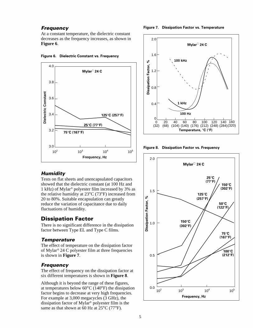
FrequencyAt a constant temperature, the dielectric constantdecreases as the frequency increases, as shown inFigure 6.
HumidityTests on flat sheets and unencapsulated capacitorsshowed that the dielectric constant (at 100 Hz and1 kHz) of Mylar® polyester film increased by 3% asthe relative humidity at 23°C (73°F) increased from20 to 80%. Suitable encapsulation can greatlyreduce the variation of capacitance due to dailyfluctuations of humidity.
Dissipation FactorThere is no significant difference in the dissipationfactor between Type EL and Type C films.
TemperatureThe effect of temperature on the dissipation factorof Mylar® 24 C polyester film at three frequenciesis shown in Figure 7.
FrequencyThe effect of frequency on the dissipation factor atsix different temperatures is shown in Figure 8.
Although it is beyond the range of these figures,at temperatures below 60°C (140°F) the dissipationfactor begins to decrease at very high frequencies.For example at 3,000 megacycles (3 GHz), thedissipation factor of Mylar® polyester film is thesame as that shown at 60 Hz at 25°C (77°F).
Figure 6. Dielectric Constant vs. Frequency
3.0
3.2
3.4
3.6
3.8
4.0
102 103 104 105
75°C (167°F)
25°C (77°F)
125°C (257°F)
Frequency, Hz
Die
lect
ric
Co
nst
ant
Mylar 24 C

6
HumidityAn increase in relative humidity from 20 to 80% at23°C (73°F) caused an increase in the dissipationfactor of 12% at 1 kHz and 40% at 100 Hz.
Insulation ResistanceOne of the outstanding properties of Mylar® Type Cpolyester film is its high insulation resistance over awide temperature range. Of the commonly used
dielectrics, only polystyrene and polyethyleneexhibit a higher resistivity, but their use is limitedby a relatively low softening temperature. Theeffect of temperature on the insulation resistance ofMylar® is shown in Figure 9. This study was madeusing 0.5 µF film-foil capacitors wound withMylar® 24 C as the dielectric material and mea-sured 100 V DC.
1
100
1,000
10,000
100,000
1,000,000
10
2
46
20
4060
200
400600
2,000
4,0006,000
20,000
40,00060,000
200,000
400,000600,000
40 (104)
60 (140)
80 (176)
100 (212)
120 (248)
140 (284)
160 (320)
20 (68)
Mylar 24 C
Temperature, °C (°F)
Insu
lati
on
Resis
tan
ce, M
Ω-µ
F
Mylar 48 EL
Figure 9. Insulation Resistance vs. Temperature
7
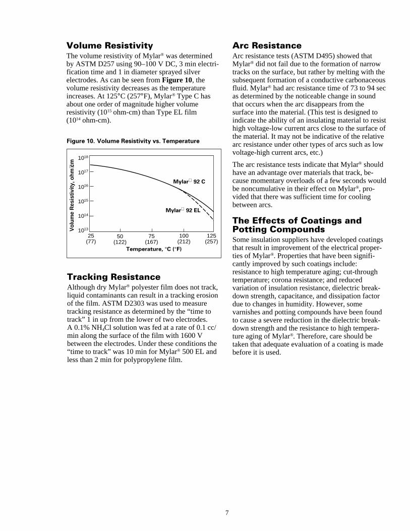
Volume ResistivityThe volume resistivity of Mylar® was determinedby ASTM D257 using 90–100 V DC, 3 min electri-fication time and 1 in diameter sprayed silverelectrodes. As can be seen from Figure 10, thevolume resistivity decreases as the temperatureincreases. At 125°C (257°F), Mylar® Type C hasabout one order of magnitude higher volumeresistivity (1015 ohm-cm) than Type EL film(1014 ohm-cm).
Arc ResistanceArc resistance tests (ASTM D495) showed thatMylar® did not fail due to the formation of narrowtracks on the surface, but rather by melting with thesubsequent formation of a conductive carbonaceousfluid. Mylar® had arc resistance time of 73 to 94 secas determined by the noticeable change in soundthat occurs when the arc disappears from thesurface into the material. (This test is designed toindicate the ability of an insulating material to resisthigh voltage-low current arcs close to the surface ofthe material. It may not be indicative of the relativearc resistance under other types of arcs such as lowvoltage-high current arcs, etc.)
The arc resistance tests indicate that Mylar® shouldhave an advantage over materials that track, be-cause momentary overloads of a few seconds wouldbe noncumulative in their effect on Mylar®, pro-vided that there was sufficient time for coolingbetween arcs.
The Effects of Coatings andPotting CompoundsSome insulation suppliers have developed coatingsthat result in improvement of the electrical proper-ties of Mylar®. Properties that have been signifi-cantly improved by such coatings include:resistance to high temperature aging; cut-throughtemperature; corona resistance; and reducedvariation of insulation resistance, dielectric break-down strength, capacitance, and dissipation factordue to changes in humidity. However, somevarnishes and potting compounds have been foundto cause a severe reduction in the dielectric break-down strength and the resistance to high tempera-ture aging of Mylar®. Therefore, care should betaken that adequate evaluation of a coating is madebefore it is used.
Figure 10. Volume Resistivity vs. Temperature
Temperature, °C (°F)
Vol
ume
Res
istiv
ity, o
hm⋅c
m
25 (77)
50 (122)
75 (167)
100 (212)
125 (257)
10
10
10
10
10
10
13
14
15
16
17
18
Mylar 92 C
Mylar 92 EL
Tracking ResistanceAlthough dry Mylar® polyester film does not track,liquid contaminants can result in a tracking erosionof the film. ASTM D2303 was used to measuretracking resistance as determined by the “time totrack” 1 in up from the lower of two electrodes.A 0.1% NH4Cl solution was fed at a rate of 0.1 cc/min along the surface of the film with 1600 Vbetween the electrodes. Under these conditions the“time to track” was 10 min for Mylar® 500 EL andless than 2 min for polypropylene film.
MylarOnly by DuPont Teijin Films
®
These values are typical performance data for Mylar® polyester film; they are not intended to be used as design data. We believe this information is thebest currently available on the subject. It is offered as a possible helpful suggestion in experimentation you may care to undertake along these lines. Itis subject to revision as additional knowledge and experience is gained. DuPont Teijin Films makes no guarantee of results and assumes no obligationor liability whatsoever in connection with this information. This publication is not a license to operate under, or intended to suggest infringement of, anyexisting patents.
CAUTION: Do not use in medical applications involving permanent implantation in the human body. For other medical applications, see “DuPontTeijin Flms Medical Caution Statement,” H-50102-1-DTF.
(06 /2003) 216212B Printed in U.S.A.[Replaces: H-32192]Reorder No.: H-32192-1
DuPont Teijin Films 1 Discovery Drive (P.O. Box 411)Hopewell, VA 23860Product Information: (800) 635-4639Fax: (804) 530-9867