n 7 3 32621 nasa technical nasatmx-71444
TRANSCRIPT

c
NASA TECHNICALM E M O R A N D U M
N 7 3 3 2 6 2 1
NASATMX-71444
<GO<
DEMONSTRATION OF A PULSING LIQUID
HYDROGEN/LIQUID OXYGEN THRUSTER
by P.N. Herr and L. SchoenmanLewis Research CenterCleveland, Ohio 44135
TECHNICAL PAPER proposed for presentation at NinthPropulsion Joint Specialist Conference cosponsored bythe American Institute of Aeronautics and Astronauticsand the Society of Automotive EngineersLais Vegas, Nevada, November 5-7, 1973

DEMONSTRATION OF A PULSING LIQUID HYDROGEN/LIQUID OXYGEN THRUSTER
P. N. Heir* and L. Schoenman**•NASA-Lewis Research Center
**Aerojet Liquid Rocket Company
Abstract
Successful operation of a pulsing liquid hydrogen/liquidoxygen attitude control propulsion system thruster (1250 lbf)at cryogenic inlet conditions while maintaining high specificimpulse and low impulse bit capability has been demonstratedunder a technology contract. This demonstration is the result ofa continuing search for a simple, lightweight and highperformance reaction control system concept and is anadvancement in the state-of-the-art of auxiliary enginetechnology. The use of cryogenic liquid propellants withpulse-mode rocket engines has heretofore only been possiblewith the aid of heavy and complex propellant conditioningequipment to convert the cryogenic liquids to gases.
Significant technical advances and departures fromconventional injector design practices were necessary in order toachieve an operable thruster. These advancements were achievedthrough extensive analyses of heat transfer and injectormanifold priming that established the baseline feasibility for anactual hardware design. Promising results from the thermalanalysis, subscale injector chilldown tests, and ignitionexperiments at cryogenic propellant temperatures (150°Roxygen, 45°R hydrogen) led to the generation of two injectordesign concepts.
The primary subject of this paper is the result of theexperimental evaluation of the 45°R hydrogen inlettemperature injector concept. The test matrix consisted of 66hot firing tests in a heat sink thrust chamber.
The testing of a complete film cooled thruster assembly atsimulated altitude conditions will complete the scheduledtechnology effort.
A summary of analytical and experimental phases of theliquid/liquid thruster technology efforts will be discussed in thispaper.
Introduction
During the early phases of the Space Shuttle vehicledefinition and propulsion system studies (1971), severalcandidate auxiliary propulsion system concepts were proposedand evaluated by both the NASA Centers and vehicle contractorspecialists' •> •*. From these extensive study and vehicleoptimization efforts, it was concluded that the lightest weightAttitude Control Propulsion System (ACPS) for the SpaceShuttle application (1.5 to 2.3 million Ib-sec total impulse)would be a liquid hydrogen/liquid oxygen (L/L) system of thetype shown schematically in Figure 1. It was suggested that thiscould be a near ideal system if it could be made to work in asatisfactory manner*. However, major technical questionsconcerning the feasibility and operability of such a system hadnot been previously addressed and, therefore, many technicalissues such as ignition and transient-flow characteristics of thecryogenic liquid propellants remained unresolved.
An extensive technology program was initiated byNASA-Lewis in June 1972 (NAS3-16775) to resolve several ofthe basic technical issues associated with a L/L Attitude ControlPropulsion System thruster concept. Some of the criticaltechnology issues to be investigated were; low temperatureignition (liquid propellant inlet conditions), pulse modeoperation, delivered performance, combustion stability4-5, andthruster heat rejection rates to the propellant feed lines.
The specific technical issues were combined into fourbroad technical areas for parametric analyses. These areas were(1) thruster thermal management, (2) ignition requirements andlimitations, (3) performance and operational characteristics, and(4) thruster component and feed system interactions. Theresults of these parametric analyses provided design guidance indetermining which key technology areas had to bedemonstrated and aided in the formulation of preliminarydesign concepts.
In addition to the extensive analytical effort, two criticalexperimental activities were conducted in support of theparametric analyses prior to design concept selections. First, aseries of ignition limit experiments was undertaken to verify theanalytically predicted limits of ignitability of cryogenichydrogen/oxygen mixtures. Other experiments investigatedchilldown and priming characteristics of both prechilled andlow thermal capacity manifold concepts.
Thruster design configurations, based on the results of theabove analyses and experiments, were generated. Eachconfiguration was analyzed in detail using an engine simulationmodel to predict fill, ignition and shutdown transients. Thenominal design point, operating range, performance, andresponse goals selected by NASA for the demonstration engineare provided in Table I. The designs were tailored to 45°Rhydrogen and 150°R oxygen at the propellant valve inlets. The45°R hydrogen inlet temperature was selected for the nominaldesign point of the L/L injector because all systemconsiderations analyzed2'3 indicated 45°R would be a realistictemperature at which the hydrogen could be held in the vehiclesupply system and, therefore, supplied to the thrusters. Oneinjector/thruster design was fabricated and hot fired.
The following sections of this paper highlight the technicalefforts which brought the advanced thruster technology intoreality.
Thruster Configuration
Overall Thruster Analysis and Requirements
Analytical assessments of all major technical areas ofconcern associated with liquid hydrogen/liquid oxygen thrusterconcepts were conducted early in the investigation to narrowdown the number of conceptual possibilities. Severalindependen t analyses related specifically to ignitionrequirements, thermal management (propellants and hardware);
•Paul N. Herr, Project Manager, NASA-Lewis, Member A.I.A.A.
"Leonard Schoenman, Project Manager, Aerojet Liquid Rocket Company
injector design synthesis, thrust chamber cooling and feedsystem interactions were conducted to find an acceptable matchof hardware with the overall thruster operating requirements(Table I).
Injector/thruster concepts were evaluated in which eitherpropellant could be injected as received from the feed lines (i.e.,as a cryogenic liquid), or could be converted from a liquid togas prior to injection. This conversion to gas could beaccomplished by using the heat rejected from a partialregeneratively-cooled thrust chamber during steady-stateoperation, and by using residual energy in the thruster duringstart transients. Other concepts evaluated included those havingthe propellant valves located upstream or downstream of thechamber cooling jackets and the use of an interpropellant heatexchanger integral to, or separate from, the injector.
The results of these early analyses indicated thatliquid-phase oxidizer injection was most desirable in order tohave fast response and low minimum impulse bits; thisrequirement would make it necessary to maintain the oxygen ina high density liquid phase through the injector. It was alsodetermined that the internal volume and heat transfer surfacearea of the oxidizer manifold had to be minimized in order toproduce the desired pulsing characteristics over the wide rangeof inlet temperatures specified in Table I. Results of these sameanalyses indicated the hydrogen side of the injector manifoldwould not be as critical in terms of volume because of the lowerfuel density (si/20 that of L02) and the higher effective thrustderived from residual hydrogen compared to residual oxygen inthe injector manifold. Thus minimizing the oxygen manifoldvolume was a design driver. The LH2 density change due to heatabsorption in the injector manifold was more critical than thatof the LO2. These two considerations ultimately dictated thepropellant valve and manifold masses, shapes and locations.
Results of this analysis also indicated that the physicalstate of the propellants to the igniter assembly could not beguaranteed because of the low flow rates and wide range ofduty cycles. Thus, an igniter design which could operate in theL/L, G/L, or G/G mode was required.
Thrust chamber cooling analyses indicated a simplefilm-cooled thrust chamber could probably provide reasonableperformance and life margins while still meeting the operationalrequirements of both pulsing and steady-state modes of firing.
Ignition Considerations
Igniter design considerations included energy levelrequirements, propellant flow and mixture ratio requirements,ignition sources, propellant inlet sequencing, overall totalignition energy requirements (torch vs. other igniterapproaches) and inlet temperature and chamber pressurelimitations.
Preliminary ignition system analyses and laboratory scaleignition experiments indicated that it would be extremelydifficult to control the density of the small quantities ofpropellant reaching the igniter. It was, therefore, necessary todevelop an igniter design that could function nearlyindependently of. the physical state or quantity of thepropellants being supplied to it. Two criteria were established
for any igniter design: first, that the mixture ratio in theprimary ignition zone should be centered in the broad band ofthe H-O ignitability range (2-90), which corresponds to amixture ratio (MR) of about 40:1; and second, that the totalenergy level of the igniter torch should be sufficiently high,even in a low flow (vapor restricted) condition, to ensurereliable ignition of liquid phase propellants in the thruster.
An igniter design that could provide reliable and rapidthruster ignition while accepting H2 and O2 in a gas, liquid, ortwo-phase state was configured based on MR and flowrequirements and the successful results of the high MR sparkgap, capacitive discharge ignition system previouslydeveloped7-11. The only operational constraint assumed wasthat both fuel and oxidizer must be supplied to the igniterassembly at close to the same temperature. This could beaccomplished easily by the use of tangent or coaxial feed linesor other forms of an interpropellant heat exchanger. Since theflow rates of propellants employed in the igniter are very small(O.I Ib/sec), such a device would also be very small.
Spark energy effects were investigated experimentally andit was concluded that 10 mJ of spark energy was sufficient toprovide reliable ignition under all circumstances where anignitable mixture was present in the spark gap area.
The complete ignition system consists of five majorcomponents: (1) a spark plug, (2) valves, (3) a body that formsor contains all manifolding and seals, propellant metering andinjection orifices, a platform for mounting the spark plug andvalves and all necessary instrumentation ports, (4) a hydrogencooled nickel chamber, and (5) a high voltage capacitancedischarge power supply.
In the selected igniter design concept, shown in Figure 2,the fuel flows from an annular manifold into parallel coolantand injection flow passages. A small portion of the hydrogen(10%) is injected into the igniter chamber where it impinges onthe spark-excited oxygen, producing ignition within the igniterat a high mixture ratio (s40:l). The bulk of the fuel (90%)bypasses the primary reaction zone (kernel zone) and is used asigniter coolant. This fuel coolant is ducted down slottedpassages formed between the igniter combustion chamber sleeveand the internal cavity of the injector (igniter port) into whichthe igniter assembly is inserted. The passage dimensions wereselected to provide adequate convective cooling of the ignitercombustion chamber that contains the high mixture ratio hotgas. The coaxial core (MR 40) and coolant streams partially mixwhen the coolant sleeve is terminated upstream of the igniterthroat. The secondary fuel added to the oxidizer rich core raisesthe torch combustion temperature and film cools the igniterthroat. The hot (24500°R) gases from the igniter torch providethe energy source for thruster ignition. This oxidizer-augmentedspark-torch igniter concept which was developed under contractNAS3-143487, was redesigned to: accept both gas and liquidphase propellants; provide proper cold flow pressure over thetotal propellant temperature range of interest (37°R-530°R);integrate the valves to reduce dribble volume; and interface witha liquid hydrogen/liquid oxygen injector concept. The flowcharacteristics of the oxidizer-gap, capacitive discharge spark,torch-igniter design were modified to provide an ignitablepropellant mixture ratio in the spark gap (core) region thatvaried from a MR of 20 to 60 as the propellant temperatures

varied within their specified ranges. The igniter was alsodesigned to provide adequate total flow to ignite the thrusterwith corresponding variations in overall MR from 2 (3600° R) toMR 6 (6300° R).
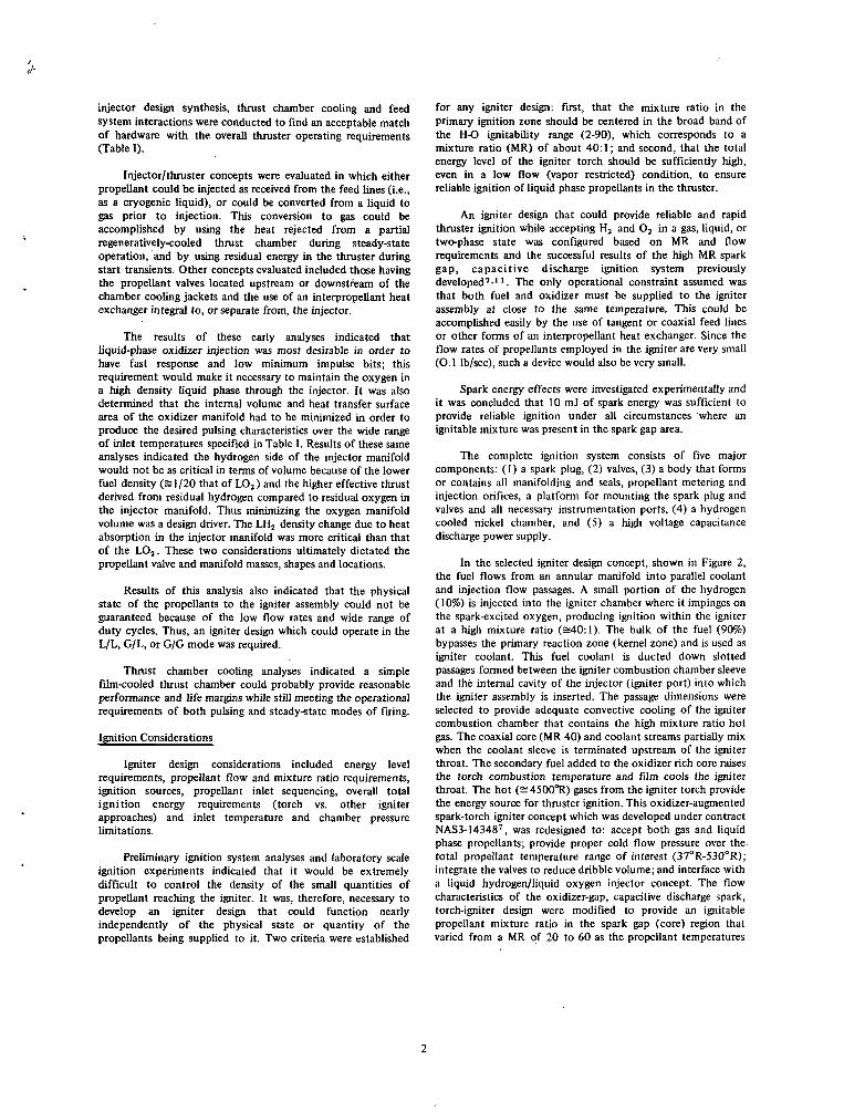
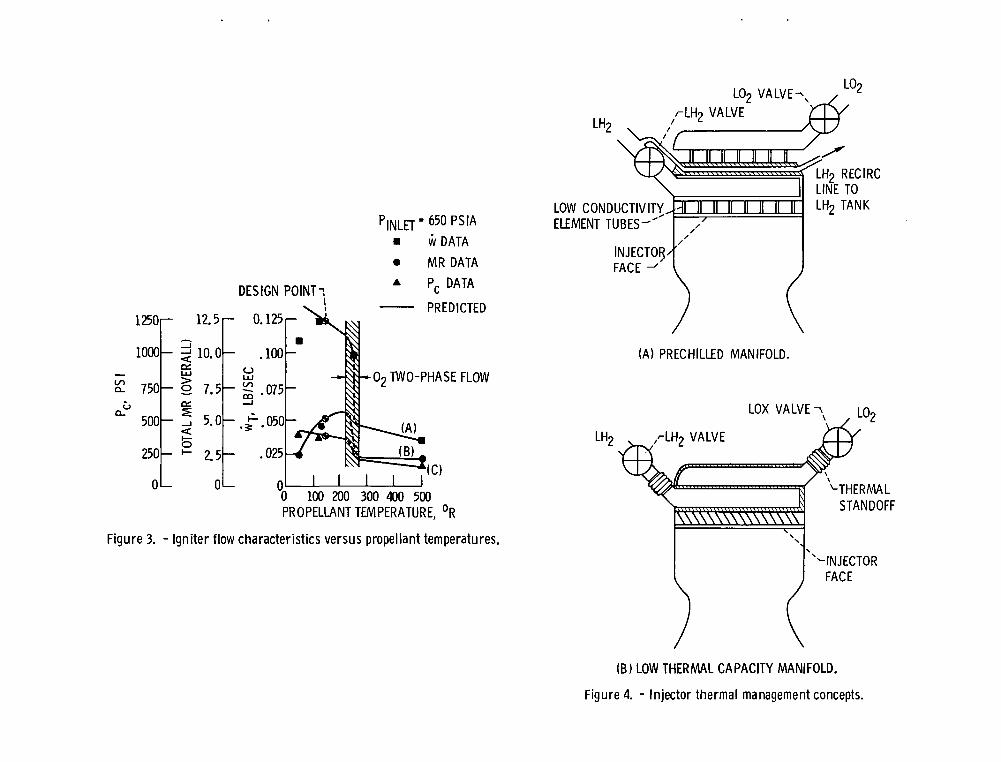
The variations of igniter propellant flow, mixture ratio andPc with propellant temperature are shown in curves A, B and Cof Figure 3. Curve A shows that the total propellant flowthrough the igniter decreases as the temperature of thepropellants increase. A large uncertainty in flow exists in thetwo-phase oxidizer region. The minimum flow, even in a fullvapor restricted condition (gas-gas), is noted to beapproximately an order of magnitude greater than the valuerequired for thruster ignition. Significant variations in theigniter mixture ratio are also to be noted (curve B); all ratios arereadily ignitable. A total MR of 2.5 (core = 25) is indicatedwhen both propellants are in the liquidous state. The total MRrises with increasing supply temperature and reaches amaximum of 5.8 (core = 58) when the oxidizer is liquid and thefuel is supercritical gas. The MR then drops rapidly withincreasing temperature as the oxidizer also becomes a gas to aMR of 2.0 (core = 20). Curve C of Figure 3 shows therelationship of Pc with propellant flowrate which alsodecreases as the flow rate was reduced, but still within theflame-quenching and spark standoff propellant cold flowlimitations.
Injector Design Considerations
Detailed feasibility analyses were conducted on severalcandidate injector start concepts (i.e., dry start and prechilled)in conjunction with suitable thruster designs. The followingitems were evaluated: Injector element type, manifold design,propellant distribution techniques, propellant freezing withininjector body, injector face temperature profiles, injectormaterial selections (considering low vs. high conductivitymaterials), injector performance predictions, injector transientflow considerations, fill times, flow instability tendencies,propellant pressure drops, velocity ratios and propellant densityeffects- all at the operational conditions specified in Table I.
Any LH2/LO2 pulsing injector design concept mustconsider several potential thermal management problems: (1)freezing of the oxidizer by exposure to the temperature of thefuel (45°R), (2) warming or vaporization of the fuel by heatingfrom the oxidizer, (3) warming or vaporization of both theoxidizer and fuel by heat contained in the injector body. For adry start, nonprechilled manifold design, the last of the abovethree problems is the most difficult to solve. If not resolvedsatisfactorily, uncontrolled propellant density changes willoccur that will seriously affect thrust level, mixture ratio, andpulse profiles. Uncontrollable propellant flows would result inthe following detrimental thruster behavior:
a. Poor pulse repeatability and erratic startup andshutdown transients.
b. Erratic ignition.c. Low pulse specific impulse.d. Local injector and chamber overheating.
Satisfactory theoretical solutions to these problems werefound by: (1) minimizing the thermal energy input from thecombustor to the injector in both steady-state and transient
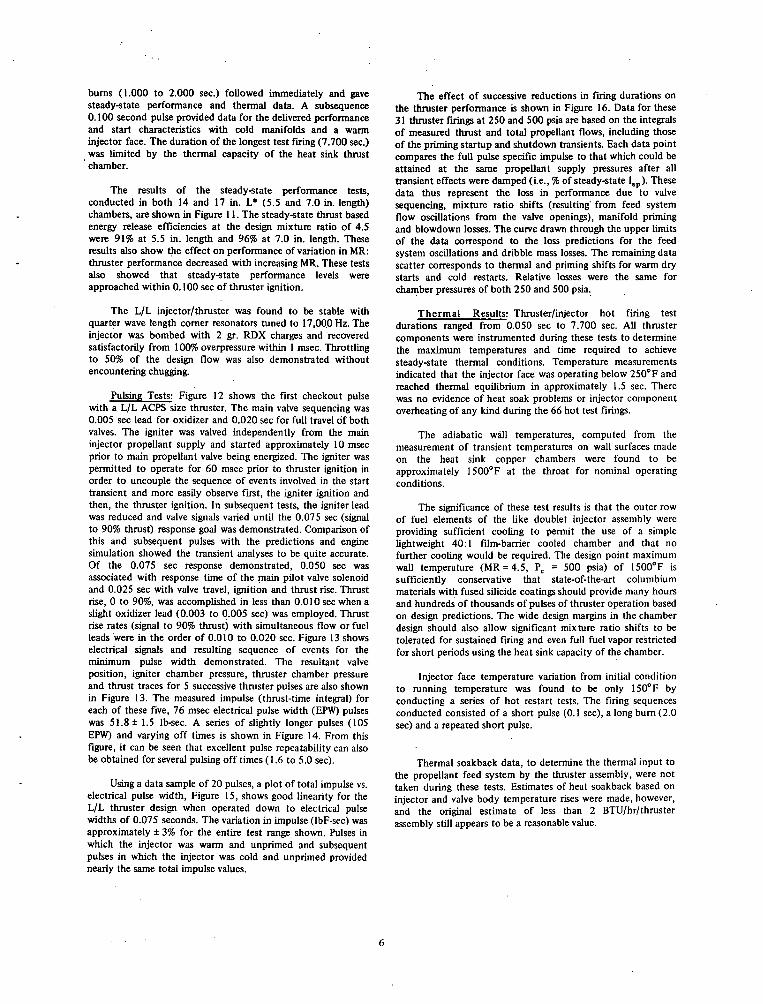
operation, and (2) controlling the rate at which the energystored in the injector hardware is transferred to the propellantsduring thruster startup. The generation of fabricable anddurable design concepts that would satisfy these requirementsrequired careful attention to propellant manifold design,injector face cooling, and injector/thruster interface. Severalbaseline injector concepts were evaluated in an enginesimulation model that computed the startup, ignition, andshutdown transients. The results of this feasibility analysisindicated the desired objectives could probably be achieved byeither of two different design approaches shown in Figure 4: (1)Prechilled Manifold (fig. 4a) - conventionally constructed andmanifolded designs, prechilled by propellant recirculation toallow rapid response; and (2) Low Thermal Capacity Manifold(fig. 4b) - designs which do not require temperatureconditioning and which are fabricated from thin walled tubular,platelet or honeycombed materials, or design that utilizesinternally insulated manifold designs of materials having verylow thermal conductivities.
The prechilled manifold approach maintains the valves,injector manifolding and igniter at cryogenic temperature suchthat the injector is chilled and ready to fire at all times. Thetemperature conditioning is obtained by low velocityrecirculation of propellants through special injector manifoldsand back through the vehicle feed system. In this design, eachcooled injector manifold is thermally isolated from each other,the surrounding structure and as much as possible from theinjector face by thermal standoffs. Propellants to be combustedare routed from the manifolds to the face through longthin-wall tubes, which reduce heat flow from the warm injectorface back to the manifold. Calculated heat leaks for thisconcept, i.e., heat that would be transferred back to the feedsystem by recirculation, were found to be 20 to 30 BTU/hr(prefire condition) which is at least an order of magnitudegreater than the systems study2 considered acceptable.
The low thermal capacity manifold approach does notemploy propellant recirculation to keep the injector cold.Instead, it utilizes a thermal standoff between the valve andthruster manifolds so that propellants may be maintained asliquids at the valves for long periods with minimal heating fromthe injector or thruster. It was analytically predicted that thisdesign concept would have slightly poorer start and pulsecharacteristics than the chilled design. It does, however,significantly reduce the heat leak to the propellant feed systemfor the same manifold volume (=2 BTU/hr/thruster). In orderto obtain a fast and repeatable starting characteristic from anonchilled injector with liquid propellants, it was deemednecessary to limit the heat input to the incoming propellants bycoating the propellant flow passages with a thermally insulatingmaterial, such as sprayed on teflon6, or devising a manifoldstructure of very low total heat capacity. Both approacheswould accelerate the internal surface chilldown and reducepropellant vapor generation'during the start transients. A reviewof the anticipated fabrication difficulties that could beencountered with the application and durability of a thermallyinsulating material made this approach less desirable and,therefore, it was dropped in favor of the low thermal capacitydesign using a double-walled manifold concept. Injectorchilldown cold-flow experiments were conducted to aid inselection between the prechilled manifold concept and the lowthermal capacity manifold concept.

For the low thermal capacity concept, a unique dual-wallmanifold was devised, which employs locally supported0.005-in. thick stainless steel manifold liners, as shown in Figure5. The support spacing and diameter was based on structuralanalyses and permits safe manifold operation up to 1000 psia.Experimental data from the dual wall manifold chilldown testsare also shown in Figure 5, in which the initially ambienttemperature dual wall manifold is exposed to sudden flows ofLO2 (=160°R) at pressures of 483, 750 and 1116 psi. Thesetests demonstrated the structural durability of the dual wallmanifold design concept and showed that the actual chilldownrates were generally faster than the predicted values. Manifoldsurface temperatures reached the LO2 liquidous temperaturewithin 0.020 seconds from first indication of propellant flow.The predicted reduced heat input to the feed system and betterstructural characteristics of the low thermal capacity designusing the dual wall manifold concept and its favorable quickchilldown characteristics resulted in a decision to employ thisconcept in the full-scale injector designs.
In order to select the injector element design, thefollowing injector element types were analyzed: H-O-Hnoncircular orifice triplet (rectangular hydrogen and circularoxygen orifices), concentric tube, and like doublet. Each ofthese element types was considered capable of providingacceptable performance, chamber wall compatibility, injectorface heat flux, and combustion stability. Elements having lowthermal contact area with the propellants were considered moredesirable. The noncircular triplet and concentric tube elementswere found to be less favorable than the like doublet becausethey resulted in increased heated surface/flow area ratio of thefuel circuit and hence caused a greater tendency to thermallychoke. The number of concentric tube elements was limited to15 because of the high injection velocities required and the highfuel density resulting in a small annulus gap size (a.007 in.).The predicted Energy Release Efficiency (ERE)* of a 24element like-on-like doublet was determined to beapproximately 1.5 to 2.0% lower (96-97% ERE) than the H-O-Htriplet element design, but was selected over the triplet on thebasis of predicted better start transient tendencies, stability,more favorable chamber wall compatibility and ease offabrication.
A major factor in injector face cooling design involved theproper selection of injection pattern that would recirculateunburned relatively cool propellant near the face. Each of theelements discussed earlier was configured to insure a fuel richenvironment near the injector face. In the like doublet design,long oxidizer and short fuel impingement lengths wereemployed. In addition, a cooling circuit, which utilizes 7% ofthe fuel was incorporated within the injector design betweenthe combustion gases and the propellant injection orifice planeto preclude heat penetration into the orifices and manifoldsduring periods of sustained firing. The deep-cup effect of eachinjector element shown in Figure 6 is the result of placing amultiple pass cooling circuit between the injection orifices andthe combustion gases. The strategically located smaller holes arethe face bleed cooling ports. Prediction of the temperatureprofile on the injector face showed that injector facetemperature at any location should not exceed 350°F understeady-state firing conditions.
The final configuration of the like doublet injectordesigned to operate with LH2/LOj is a 24-element designshown in Figure 7. It has the following features:
• An actively fuel-cooled face to preclude thermalpenetration to the injection orifices and feedmanifolds.
• Dual wall, low thermal capacity, low volumemanifolding in both propellant circuits to allow rapidpropellant bleed in and fill and thus good pulsingperformance.
• Low volume, integral valve seat assemblies that arethermally isolated from the injector body.
• An injector/chamber interface that forms a cooledcorner resonator cavity tuned as a quarter-wavelength cavity to suppress the first tangential and firsttangential plus first radial instability modes of 17 and16 KHz, respectively.
• A central port that accommodates the spark torchigniter.
The 24-element like-on-like doublet element injector facepattern is configured so that the outer row of this configurationconsists of 16 fuel pairs oriented 15° to the chamber radius.The successive inner rows consisted of 16 oxidizer pairs, 8 fuelpairs and another 8 oxidizer pairs all oriented 15° to thechamber radius. The inner row of oxidizer elements wasdesigned to mix with the centrally located igniter whichproduces a fuel-rich torch.
Figure 7 also shows that the LO2 discharges from the valveand passes through the thin wall thermal standoff (3.5 in. lengthof 0.008 in. wall, 0.354 in. dia. 321 stainless steel tube, formedas a bellows to an effective length of 0.5 in.) into a low volumetapered toroidal flow distribution manifold. The oxidizer thenpasses through 12 equally spaced flow distribution orificesdischarging into a disk shaped, dual-wall plenum, which in turnsupplies propellant to the 24 oxidizer doublet elements. Themeasured propellant volume between the propellant valve sealand discharge end of the propellant injection orifices is 0.45 in3
for the oxidizer circuit. Flow from the fuel valve located on theopposite side divides and flows through two short thin wall linesprior to passing through two symmetrically located thermalstandoffs. The fuel discharges directly into the dual wall fuelmanifold from which the 24 doublet fuel elements and facecooling circuit are supplied. The measured propellant volumebetween the valve seal and discharge end of the propellantinjection orifices for the fuel circuit is 0.64 in3.
The propellant valves are structurally attached to theinjector through laminated, low thermal conductivityglass/phenolic rings, as shown in Figure 8. Each propellant valvecontains a bleed port at the upstream edge of the seal, whichpermits priming of the valves without passing propellantsthrough the injector.
A f u l l combust ion s tabi l i ty analysis of allinjector/combustor combinations was undertaken and the mostlikely modes of instability were identified. The first longitudinalmode was not considered troublesome because it could easily beeliminated by proper selection of chamber length. The first
'Based on JANNAF vaporization, mixing models and combustion models.

tangential and first tangential plus first radial modes wereconsidered most likely to occur and potentially the mostdestructive (17 and 16 KHz, respectively). The energy level ofhigher modes was considered to be small. Helmholtz and 1/4wave length resonators tuned to attentuate the first tangentialand first tangential plus first radial modes were evaluated. A 1/4wave length corner cavity providing an effective area equal to20% of the chamber cross section, was incorporated into theinjector design from inception, including the necessaryprovisions for cooling the cavity.
Low frequency (chugging modes) were evaluated by meansof a conventional double dead time analysis with an appropriaterange of assumptions made for vaporization and mixing times.The pressure drops for each of the above injection elementtypes were selected on the basis of these analyses. The oxidizerAP/PC for the selected 24 element like doublet injector designwas 0.27 and fuel AP/PC was 0.20, based on a chamber pressureof 500 psia and liquid flows at nominal design temperatures.
Thrust Chamber Considerations
There are normally several thrust chamber cooling schemessuitable for auxiliary engine designs (i.e., ablative, film,radiation, dump, barrier and partial regenerative orcombinations of these); however, the selection is much morelimited for a rocket engine that is intended to pulse hundreds ofthousands of firings and still maintain good performancecharacteristics as well as exhibit repeatable, sharp starttransients. Only film and dump cooled chamber conceptsappeared viable for the L/L hydrogen/oxygen thrusterapplication. Regenerative cooled chambers were ruled out ontwo counts: (1) poor startup and tailoff transients due to largecoolant passage volumes, and (2) non-predictable propellantdensity within and discharging from the hydrogen coolantjacket. Ablative cooled chambers were not considered suitablebecause of possible oxygen attack and limited life. The resultsof the complete thruster thermal and cooling analyses indicatedit would be very desirable to select a thruster design/materialcombination that could withstand momentary high mixtureratios without damage to the thrust chamber.
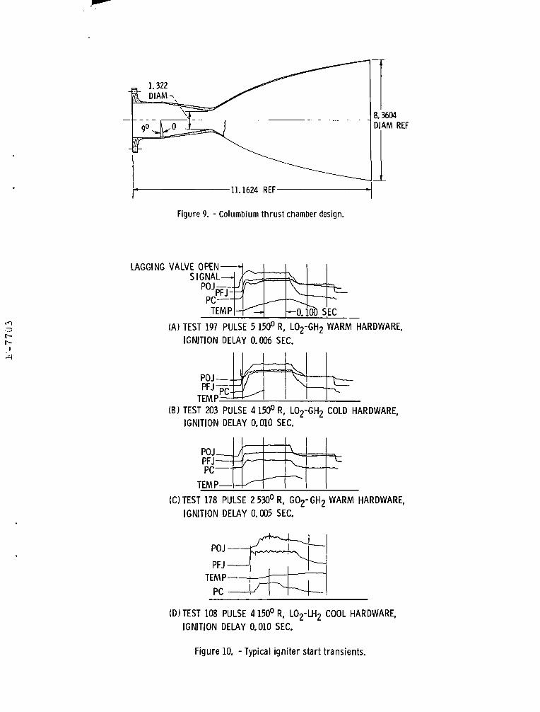
With all of the above evaluations and design considerationscompleted (including data from heat sink chamber tests), thethrust chamber cooling concept selected for the L/L thrusterapplication was a film-barrier cooled design shown in Figure 9.The one disadvantage of the film-barrier cooled chamber is theperformance losses associated with the coolant flowrequirements. At a nominal MR of 4.5, the chamber is designedto operate at a maximum throat temperature of 1500°F; theequivalent of 44% fuel film cooling being derived from theouter row of injector fuel doublets. However, for this samethrust chamber design to survive a short duration (0.1 to 0.3seconds) of high mixture ratio operation (i.e., 6.5 to 7.0), it hadto be fabricated from a material that could operate at 3000°Fin the throat and remain undamaged. To meet this operatingrequirement, columbium alloy FS85 with an oxidation-resistantfused-silicide coating was selected.
Experimental Results
Ignition Tests
consistently demonstrated with gaseous, two-phase and liquidoxygen/gaseous hydrogen propellants at temperatures rangingfrom 134 to 520° R, mixture ratios from one-half to two timesthe nominal values, and flow rates down to 25% of design
1 values. Subsequent testing provided comparable data for liquid| hydrogen inlet temperature down to 44° R. Exciter power levels
of 10 mJ were used for reliable ignition; this power level hasbeen demonstrated to be compatible with very long electrodelife'.
A series of full-scale igniter assembly tests with the unitshown in Figure 2 was conducted prior to the initiation of theinjector/thruster assembly testing. Approximately 250 hot testswere conducted with this prototype igniter. Rapid andrepeatable ignitions were again demonstrated with this unit overthe following range of test conditions:
O2 temperature (at valve)H2 temperature (at valve)Pressure (O2 valve)Pressure (H2 valve)Flow rateMR (overall)Ambient pressureHardware temp
134to520°R44to518°R330 to 910 psia309 to 924 psia0.04to0.1251b/sec2.5 to 7.5less than 0.5 psia150to530°R
Satisfactory ignitions were demonstrated with LH2/LO2,GH2/LO2, GH2/LO2 plus GO2 and GH2/GO2 supplied to thevalves with spark plug power levels of 10 mJ. Ignition wasdetected by a rise in the igniter chamber pressure within .020sec. from the time fuel or oxidizer pressure was sensed in theigniter manifolds. This was true for all propellant supplyconditions listed above. Thermocouples located in the igniterthroat and exhaust stream were also used to verify that ignitionhad occurred. Igniter durability and cooling was demonstratedby continuous firings of up to 10 sec. and pulse trains consistingof twenty 0.20 sec. firings in rapid succession (= 0.500 secbetween firings). No cooling problems were encountered.Typical igniter oscillograph traces and ignition delay times areshown in Figure 10 for (a) cold propellants (150°R), warmhardware (540°R), (b) cold propellants (150°R), cold hardware(150°R), (c) warm propellants (530°R), warm hardware(540°R), and (d) liquid propellants (49°R H2-141°R O2) andcold hardware (260°R).
Injector Tests
Steady-State Performance; A series of 66 hot firings wasmade using the like doublet injector/thruster shown in Figure 8with heat sink thrust chambers. During these hot firings, thefollowing range of test conditions were covered:
PC (psia).MRFuel temp, °ROx temp, °RInjector body temp, °R*Injector face, °R«Duration min/max sec
*At fire signal
237 - 4903-1049-70166-184160-530500-600.076/7.700 sec
In ignition feasibility tests using laboratory type igniterhardware, ignition delays of less than 0.020 sec. were
The first start of each test series was a short pulse (0.100 sec.)which provided data for a warm-manifold dry-start. Longer
burns (1.000 to 2.000 sec.) followed immediately and gavesteady-state performance and thermal data. A subsequence0.100 second pulse provided data for the delivered performanceand start characteristics with cold manifolds and a warminjector face. The duration of the longest test firing (7.700 sec.)was limited by the thermal capacity of the heat sink thrustchamber.
The results of the steady-state performance tests,conducted in both 14 and 17 in. L* (5.5 and 7.0 in. length)chambers, are shown in Figure 11. The steady-state thrust basedenergy release efficiencies at the design mixture ratio of 4.5were 91% at 5.5 in. length and 96% at 7.0 in. length. Theseresults also show the effect on performance of variation in MR:thruster performance decreased with increasing MR. These testsalso showed that steady-state performance levels wereapproached within 0.100 sec of thruster ignition.
The L/L injector/thruster was found to be stable withquarter wave length corner resonators tuned to 17,000 Hz. Theinjector was bombed with 2 gr. RDX charges and recoveredsatisfactorily from 100% overpressure within 1 msec. Throttlingto 50% of the design flow was also demonstrated withoutencountering chugging.
Pulsing Tests: Figure 12 shows the first checkout pulsewith a L/L ACPS size thruster. The main valve sequencing was0.005 sec lead for oxidizer and 0.020 sec for full travel of bothvalves. The igniter was valved independently from the maininjector propellant supply and started approximately 10 msecprior to main propellant valve being energized. The igniter waspermitted to operate for 60 msec prior to thruster ignition inorder to uncouple the sequence of events involved in the starttransient and more easily observe first, the igniter ignition andthen, the thruster ignition. In subsequent tests, the igniter leadwas reduced and valve signals varied until the 0.075 sec (signalto 90% thrust) response goal was demonstrated. Comparison ofthis and subsequent pulses with the predictions and enginesimulation showed the transient analyses to be quite accurate.Of the 0.075 sec response demonstrated, 0.050 sec wasassociated with response time of the main pilot valve solenoidand 0.025 sec with valve travel, ignition and thrust rise. Thrustrise, 0 to 90%, was accomplished in less than 0.010 sec when aslight oxidizer lead (0.003 to 0.005 sec) was employed. Thrustrise rates (signal to 90% thrust) with simultaneous flow or fuelleads were in the order of 0.010 to 0.020 sec. Figure 13 showselectrical signals and resulting sequence of events for theminimum pulse . width demonstrated. The resultant valveposition, igniter chamber pressure, thruster chamber pressureand thrust traces for 5 successive thruster pulses are also shownin Figure 13. The measured impulse (thrust-time integral) foreach of these five, 76 msec electrical pulse width (EPW) pulseswas 51.8± 1.5 Ib-sec. A series of slightly longer pulses (105EPW) and varying off times is shown in Figure 14. From thisfigure, it can be seen that excellent pulse repeatability can alsobe obtained for several pulsing off times (1.6 to 5.0 sec).
Using a data sample of 20 pulses, a plot of total impulse vs.electrical pulse width, Figure 15, shows good linearity for theL/L thruster design when operated down to electrical pulsewidths of 0.075 seconds. The variation in impulse (IbF-sec) wasapproximately ± 3% for the entire test range shown. Pulses inwhich the injector was warm and unprimed and subsequentpulses in which the injector was cold and unprimed providednearly the same total impulse values.
The effect of successive reductions in firing durations onthe thruster performance is shown in Figure 16. Data for these31 thruster firings at 250 and 500 psia are based on the integralsof measured thrust and total propellant flows, including thoseof the priming startup and shutdown transients. Each data pointcompares the full pulse specific impulse to that which could beattained at the same propellant supply pressures after alltransient effects were damped (i.e., % of steady-state Ilp). Thesedata thus represent the loss in performance due to valvesequencing, mixture ratio shifts (resulting' from feed systemflow oscillations from the valve openings), manifold primingand blowdown losses. The curve drawn through the upper limitsof the data correspond to the loss predictions for the feedsystem oscillations and dribble mass losses. The remaining datascatter corresponds to thermal and priming shifts for warm drystarts and cold restarts. Relative losses were the same forchamber pressures of both 250 and 500 psia.
Thermal Results: Thruster/injector hot firing testdurations ranged from 0.050 sec to 7.700 sec. All thrustercomponents were instrumented during these tests to determinethe maximum temperatures and time required to achievesteady-state thermal conditions. Temperature measurementsindicated that the injector face was operating below 250°F andreached thermal equilibrium in approximately 1.5 sec. Therewas no evidence of heat soak problems or injector componentoverheating of any kind during the 66 hot test firings.
The adiabatic wall temperatures, computed from themeasurement of transient temperatures on wall surfaces madeon the heat sink copper chambers were found to beapproximately 1500°F at the throat for nominal operatingconditions.
The significance of these test results is that the outer rowof fuel elements of the like doublet injector assembly wereproviding sufficient cooling to permit the use of a simplelightweight 40:1 film-barrier cooled chamber and that nofurther cooling would be required. The design point maximumwall temperature (MR = 4.5, Pc = 500 psia) of 1500°F issufficiently conservative that state-of-the-art columbiummaterials with fused silicide coatings should provide many hoursand hundreds of thousands of pulses of thruster operation basedon design predictions. The wide design margins in the chamberdesign should also allow significant mixture ratio shifts to betolerated for sustained firing and even full fuel vapor restrictedfor short periods using the heat sink capacity of the chamber.
Injector face temperature variation from initial conditionto running temperature was found to be only 150°F byconducting a series of hot restart tests. The firing sequencesconducted consisted of a short pulse (0.1 sec), a long burn (2.0sec) and a repeated short pulse.
Thermal soakback data, to determine the thermal input tothe propellant feed system by the thruster assembly, were nottaken during these tests. Estimates of heat soakback based oninjector and valve body temperature rises were made, however,and the original estimate of less than 2 BTU/hr/thrusterassembly still appears to be a reasonable value.

Concluding Remarks
The experimental data acquired to date have demonstratedthe feasibility of pulsing a liquid hydrogen/liquid oxygenthruster over the thrust and chamber pressure ranges of 625 to1250 IbF and 250 to 500 psia, respectively. The L/L conceptnow appears to be a viable candidate for advanced spacecraft(e.g., Space Shuttle or Space Tug systems) where highperformance and the development of advanced concepts iswarranted.
The injector/thruster concept demonstrated under thesubject technology program exhibited a 0.075 'Sec responsefrom start signal to 90% thrust, does not require prechillingprior to firing, is thermally isolated from the valve and does notappear .to exceed the permissible heat leak into the vehiclepropellant feed system established by the initial vehiclestudies* >2. The experimental data also show that ignition withlow temperature propellants is rapid and repeatable and that bitimpulse is repeatable within =3% at 50-lb-sec levels. Thedeliverable vacuum specific impulse of a 17 in L*, 40:1 arearatio nozzle, barrier cooled chamber is predicted to be 427lbf-secc/lb for a complete liquid/liquid thruster assembly whensea level injector test data are extrapolated to the 40:1 nozzlevacuum conditions. This 427 Isp performance prediction isbased on a 96% ERE demonstrated by the L/L 24 elementinjector in sea level hot firings in a 17 L* chamber. However,auxiliary propulsion system performance with L/L thrusters ispredicted to be considerably higher than the systemperformance with either a gas/gas or gas/liquid thruster systemwhere "propellant conditioning" is required2.
Further activities in the optimization of the liquid/liquidinjector pattern would probably result in a 1 to 2%improvement in delivered performance. The combination ofinjector pattern, element type and L* could possibly bechanged to achieve higher performance.
All analysis and design activity associated with thistechnology program was directed, from the beginning, towardestablishing the feasibility of a pulsing liquid hydrogen/liquidoxygen injector/thruster. The L/L thruster hardware designedand tested was not an optimized "fixed point" design (i.e., for asingle chamber pressure) but was a "laboratory tool" designedto acquire experimental data over a wide range of operatingconditions. Therefore, conservatism was employed in most areasof the hardware design selections. Now that feasibility has beendemonstrated, refinement and further design iterations wouldvery likely result in an improved performance level. Also fasterresponse times could be obtained if better propellant valvingwere developed.
Further experimentation under the subject contract willinclude altitude testing of the complete cooled thrusterassembly. Additional technology work should be undertakenwhich would include the following steps to fully demonstratethe technology for a flight-type L/L thruster and a L/L H2 -O2
ACPS:
(1) Further optimization of the dual wall manifoldingconcept..
(2) Design/development of a lighter weight injectorassembly including (lightweight valves.
(3) Durability testing of the flightweight design.
(4) Insulation of the thrust chamber and evaluation ofthis effect on design margins, thruster life andthermal soakback.
(5) Demonstration of a complete propulsion systemincluding small pumps, high pressure run tanks (liquidaccumulators), lines and thrusters at simulated spaceconditions (breadboard system demonstration).
REFERENCES
I.Kelly, P. J., etal: Space Shuttle Auxiliary PropulsionSystem Design Study, Douglas Corporation, InterimSystems Definition Review, Gpntract NAS9-12013,October, 1971.
2. Bauman, T. L., etal: Space Shuttle Auxiliary PropulsionSystem Design Study, McDonnell Douglas Corporation,Contract NAS9-12013, Systems Definition Review, Feb.,1972. MDCE0603.
3. Akkerman, James W.: Shuttle Reaction Control SystemCryogenic Liquid Distribution System Study. AuxiliaryPropulsion and Pyrotechnics Branch Internal Note,Propulsion and Power Division, Manned Spacecraft Center,Sept., 1971.
4. Schoenman, L.: Extended Temperature Range ThrusterInvestigation. Monthly Reports, NASA ContractNAS3-16775, Aerojet Liquid Rocket Co., Sacramento,Calif., July 1972 through Oct. 1973.
5. Wanhainen, J. P., etal: Effect of Propellant InjectionVelocity on Screech in a 20,000-Pound Hydrogen-OxygenRocket Engine. NASA TN D-3373, April, 1966.
6. Wong, G. S.: Liquid Hydrogen Turbopump Rapid StartProgram. 8th Monthly Progress Report, ContractNAS8-27608, April, 1972.
7. Rosenberg, S. D., Aitken, A. J., Jassowski, D. M. andRoyer, K. F.: Ignition Systems for Space Shuttle AuxiliaryPropulsion System. NASA CR-72890, 1972. NASAContract NAS3-14348.
8. Senneff, J. M.: High Pressure Reverse Flow APS Engine.NASA CR-120881, Bell Aerospace Company, Buffalo,N.Y., 1972.
9. Blubaugh, W.: In tegra ted Thruster AssemblyInvestigation. Monthly Reports, NASA ContractNAS3-15850, Aerojet Liquid Rocket Co., Sacramento,Calif., July, 1972 through July, 1973.
10. Schoenman, L: Interim Report, NAS3-16775, AerojetLiquid Rocket Co., Sept. 1973.
11. Schoenman, L.: Hydrogen-Oxygen Auxiliary Propulsionfor Space Shuttle, NASA CR-120895, Aerojet LiquidRocket Co., Sacramento, Calif., January 1973.
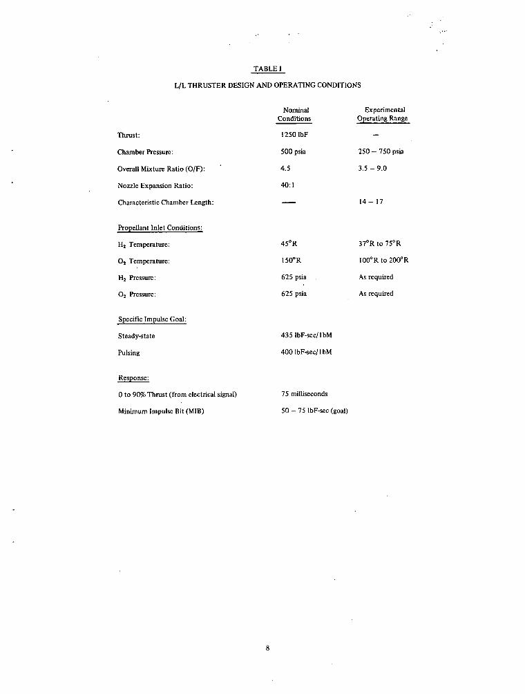
TABLE I
Thrust:
Chamber Pressure:
Overall Mixture Ratio (O/F):
Nozzle Expansion Ratio:
Characteristic Chamber Length:
Propellant Inlet Conditions:
H2 Temperature:
02 Temperature:
Hj Pressure:
O2 Pressure:
Specific Impulse Goal:
Steady-state
Pulsing
Response:
0 to 90% Thrust (from electrical signal)
Minimum Impulse Bit (MIB)
SI AND OPERATING CONDIT
NominalConditions
12501bF
500 psia
4.5
40:1
45°R
150°R
625 psia .
625 psia
4351bF-sec/lbM
4001bF-sec/lbM
IONS
ExperimentalOperating Range
-
250 - 750 psia
3.5-9.0
14- 17
37°Rto75°R
100°Rto200°R
As required
As required
75 milliseconds
50 - 75 IbF-sec (goal)

LIQUID OXYGENACCUMULATOR
LIQUID HYDROGENACCUMULATOR
L/LTHRUSTERASSY.
Figure 1. - Liquid hydrogen/liquid oxygen APS schematic.
POWERSUPPLY
OXIDIZER VALVE
FUEL VALVE
l S P A R K IGNITION
IGNITER 2rOX TORCH MR 20 - 60NJECTOR
3 rFUEL ADDITION MR 2 - 5
1 + 2 + 3 STAGES <10 MS
90% FUEL COOLING CIRCUIT
PRIMARY IGNITION
ZONE FLOW DETAILS
Figure 2. - Staged torch igniter.
t/io_
0.°
1250
1000
750
500
250
0
r- 12.5
- ^ 10.0U-J
-1 7.5em
h ^ 5.0i
h "~ 2.5
0
DESIGN POINT-,
r- 0.125
- .100oLU
U -075
-.£-.050
V- .025
P |NLET=650PSIA
• w DATA
• MR DATA
A Pc DATA
PREDICTED
09 TWO-PHASE FLOW
0 100 200 300 400 500PROPELLANT TEMPERATURE, °R
Figure 3. - Igniter flow characteristics versus propellent temperatures.
L02 VALVE-
VALVE
LOW CONDUCTIVITYELEMENT
FACE
RECIRCLINE TOLH9 TANK
(A) PRECHILLED MANIFOLD.
LOXVALVE
^THERMALSTANDOFF
INJECTORFACE
(B) LOW THERMAL CAPACITY MANIFOLD.
Figure 4. - Injector thermal management concepts.

STRUCTURE-
0.005 IN. LINER'
SUPPORTS -
100
0
-100
-200
-300
-400
L02 TEST DATA 480-1100 PSIA
r i .-FIRST INDICATIONOF FLOW
(A) OVER SUPPORTS
I j I
PREDICTED
0 .05 .10 .15TIME, SEC
BETWEEN SUPPORTS
j |0 .05 .10 .15
Figure 5. - Dual-wall low thermal capacity manifold concept.
Figure 6. - Like doublet LA injector face.

DUAL-WALL L07 MANIFOLD-L02 THERMAL STAND-OFF-
L02 VALVE
TORCHIGNITER PORT
LH2 (FUEL) INLET-FUEL THERMAL,STAND-OFF
.0918"
25°
.034" DIAM.
*>
ACTIVELY COOLED FACEAND THERMAL STAND-OFF
LIKE ON LIKE DOUBLET24 ELEMENT PATTERN
DUAL-WALL FUEL MANIFOLD
OXIDIZERELEMENTS
INJECTOR ELEMENT DETAIL.0685"
.028" DIAM.
FUELELEMENTS
IGNITER BODY-J
L02
INLET
THERMALINSULATIONBLOCKS
INLET
IGNITERCHAMBER-7
OX VALVESUPPORT
INJECTORFACE
J?V-—L THERMALSTANDOFF
Figure 8. - LHyLO;? injector assembly.
Figure 7. - LH2-L02 injector assembly.
8.3604DIAM REF
Figure 9. - Columbium thrust chamber design.
LAGGING VALVE OPEN-SIGNAL-
POJPF>PC
TEMP
(A) TEST 197 PULSE 5 150° R, L02-GH2 WARM HARDWARE,
IGNITION DELAY 0.006 SEC.
(B) TEST 203 PULSE 4150°R, L02-GH2 COLD HARDWARE,IGNITION DELAY 0.010 SEC.
POJr>r irrjPC
TEMP
/f —
^ —.
\
V.1
=t
(C)TEST 178 PULSE 2530°R, G02-GH2 WARM HARDWARE,IGNITION DELAY 0.005 SEC.
(D)TEST 108 PULSE 4150°R, L02-LH2 COOL HARDWARE,IGNITION DELAY 0.010 SEC.
Figure 10. - Typical igniter start transients.

100 f
9 0 - -
oUJ
o
t
UJ
5
7 0 - -
6 0 - -
50
'-̂ r
•
i
5.5 IN. (14L*J7"~~^ -—
"""" *^r^-^DESIGN
*" 0/F PC,PSIA
0 500* 250
OPEN: L1 =7.0 IN.SOLID: L' =5. 5 IN.DURATION: 0.25 TO 1.1TQ - 163° TO 190° RTf = 48° TO 70° R
i . i i
3 4 5 6 7 8
-~~~~~~~.
SEC
1
9MIXTURE RATIO, 0/F
Figure 11. - Liquid l^/liquid 02 injector steady state performance.
OPENFUEL VALVEPOSITION
Figure 12. - First LH2/L02 thruster firing traces.

THRUST TRACES PULSE A-E
IMPULSE, LBF-SEC 53.4 52.5 52.2 50.4
-0.008 SEC
1000
PULst
50.9
rCLOSED
DATA FOR PULSE C
SPARK ON
IGNITER FUEL FLOW
IGNITER OXIDIXER FLOW
MAIN OXIDIZER FLOWMAIN STAGE IGNITION
VALVE POSITIONS
TEST 054 PULSES A-ELH2/L02 INJECTION
OXIDIZEROPEN
0.075 TO 90% THRUST
450
0.068j0.0620.068
IGNITERPRESSURE
ENGINEPRESSURE
—TIME-
Figure 13. - LH2/L02thruster sequence, and response characteristics(pulse train 054).
h
1 1I I
1 11 (Iv- t-r t
11
1
tk _Yk.
1
1 !-A
PC Hi FREQ.
LOX MANIFOLD
PRESS.
L IGNITER CHAMBERPRESS.
I— 0. 100 SEC
THRUST
!„ OX FLOW
I FUEL FLOW
Figure 14. - UL Thruster electrical pulse width (E. P. W.) train (varying off time).

LOSSES DUE TODRIBBLE MASSAND FEED SYSTEMOSCILLATIONS^
(STEADY STATE PERFORMANCE)
FIRST PULSE
RESTART DATAo
OPEN
SOLIDRANGE OFINTEREST
I I
^MANIFOLDPRIMARY LOSTRANGE
40 50 60 70 80 90 100SEA LEVEL BIT IMPULSE, LBf-SEC («• 4.8)
Figure 15. - Bit impulse pulse performance/Sample 31 tests.
no
200
oLUon
co~
oni
=>Q_
<
O
10C-
1
Pc 500PSIA
No. TESTS
DEV.
0 100 200ELECTRICAL PULSE WIDTH, MILLISEC
300
Figure 16. -Total impulse versus electrical pulse width.
NASA-Lewis