n ·'a o - americanradiohistory.com · this capacitive leakage can be materi ... with a...
TRANSCRIPT

-
� n ·'a�o
� PEHIMENTER VOLUME XXVlll No. 11 APRIL, 195 4
Copyright, 1954, General Radio Company, Cambridge, Mass., U. S. A.
A BALANCED MODULATOR FOR
PULSE APPLICATIONS
IN THIS ISSUE
Page
AND Now - TO MONITOR COLOR TV. . . . . . . . 5
MAY- Mo TH OJ<' Ex-HIBITS . . . . . . . . . . . . . . . 7
e IN THE MARCH, 19 50, EXPERI
MENTER, a simple loss-type modulator
(TYPE 1000-P6) using a silicon-crystal
diode was described. This device made
possible wide-frequency-range amplitude
modulation of existing oscillators and signal
generators. At a nominal expenditure, test sources for pulse and video systems were
therefore made available to the engineer,
previously hampered by lack of even expensive alternatives.
Not only did this device permit modulation frequencies far in excess
of those previously available in test instruments, but also the generation
of the amplitude modulation substantially without incidental frequency
Figure 1. The Type 1000-P7 Balanced Modulator (in foreground) set up with the Type 1217-A Unit Pulser to pulse-modulate the Type 1021-A Standard Signal Generator.
www.americanradiohistory.com

GENERAL RADIO EXPERIMENTER 2
RF INPUT
modulation. The modulator was therefore useful not only for television, radar, and other applications requiring wideband modulation but also for a-m tests on f-m systems and for tests of omnirange equipment, where freedom from f m is essential.
The success of this device for simple uses has led to the development of a more sophisticated device, the TYPE
1000-P7 Balanced Modulator, which has a still wider range of applications than the single-diode model.
The limitations of the TYPE 1000-P6 Crystal-Diode Modulator arose principally from the capacitive leakage that occurred when the crystal impedance
was high. This reduced the percentage modulation at high carrier frequencies below that which could be obtained at low frequencies and thereby limited its usefulness.
This capacitive leakage can be materially reduced and, in fact, a nearly perfect null obtained at a particular value of modulating voltage, by adjusting the resistive balance as well as the capacitive balance in a balanced-modulator circuit using two crystals. With this method of operation, used in the TYPE
1000-P7 Balanced Modulator, pulse modulation with 60 db ratios of off-on can be achieved, as well as substantially perfect 100 per cent modulation for video testing.
Figure 2. Elementary schematic circuit diagram of the Type 1 OOO-P7 Balanced Modulator.
(fr====:::::ir-__J Nf
RF OUTPUT
���--1'-'"*I--t-lf--I
BALANCE
MODULATION
CIRCUIT
The elementary schematic illustrates the principle of operation of the TYPE
1000-P7 Balanced Modulator. Two crystals are used, with a phasing line so arranged that the carrier voltage applied to one diode is 180 degrees out of phase with the carrier voltage applied to the other. The relative bias currents applied to the diodes can be adjusted to equalize their impedances and consequently produce a null in the carrier output.
The adjustable phasing line is a "trombone" section of coaxial line, which must be set to an odd multiple of onehalf wavelength at the carrier frequency. The BALANCE control is a differential control in the bias supply. A BIAS control, not shown in the schematic, is provided which permits setting the operating point on the diode characteristics for best linearity and which also operates a switch in the extreme counterclockwise position to disconnect the bias battery.
The diodes are oppositely poled so that an applied pulse or modulating signal increases the impedance of one while decreasing the impedance of the other. A pulse of either polarity will drive the circuit from the initial balanced condition to produce a pulse of radio-frequency output. The carrier level between pulses depends on the degree of balance of the circuit. It is relatively easy to obtain a residual carrier level
60 decibels below the pulsed level. For the usual amplitude-modulation
applications, the BALANCE control can be offset to insert the desired amount of carrier. Since the modulator can be operated as close to balance as desired, very good linearity can be obtained. With proper adjustment of BIAS and BALANCE controls, good linearity at 100 per cent modulation can be obtained with 10 millivolts of radio-frequency
www.americanradiohistory.com
3
output on modulation peaks. The oscillogram of Figure 3 shows the modulation characteristic obtained at a carrier frequency of 900 megacycles at this output level.
CONSTRUCTION
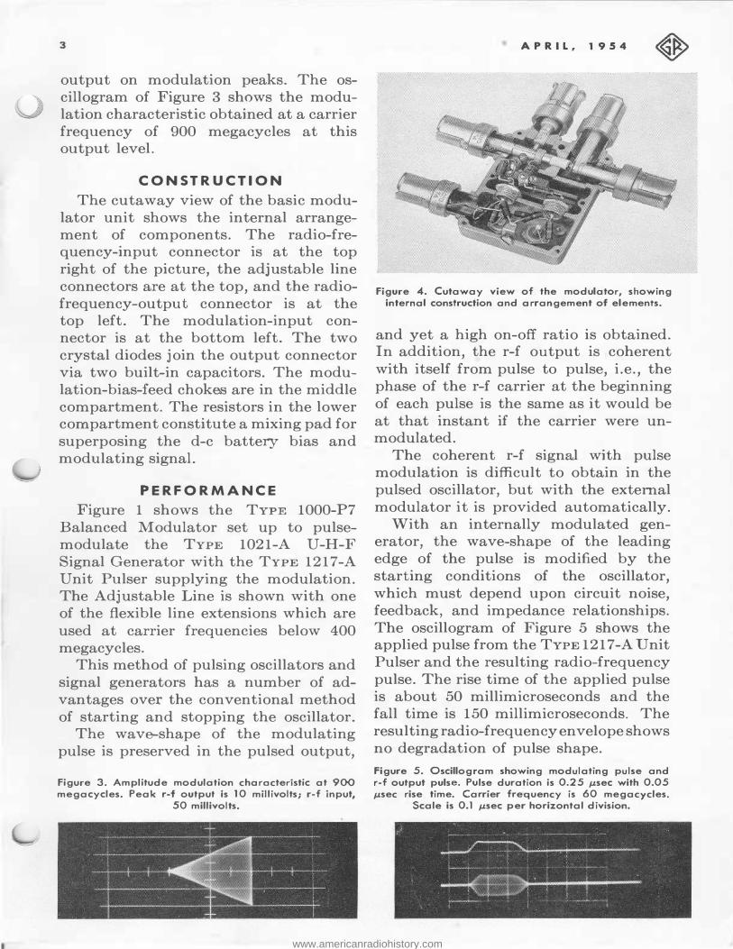
The cutaway view of the basic modulator unit shows the internal arrangement of components. The radio-frequency-input connector is at the top right of the picture, the adjustable line connectors are at the top, and the radiofrequency-output connector is at the top left. The modulation-input connector is at the bottom left. The two crystal diodes join the output connector via two built-in capacitors. The modulation-bias-£ eed chokes are in the middle compartment. The resistors in the lower compartment constitute a mixing pad for superposing the d-c battery bias and modulating signal.
PERFOR MANCE
Figure 1 shows the TYPE 1000-P7 Balanced Modulator set up to pulsemodulate the TYPE 1021-A U-H-F Signal Generator with the TYPE 1217-A Unit Pulser supplying the modulation. The Adjustable Line is shown with one of the flexible line extensions which are used at carrier frequencies below 400 megacycles.
This method of pulsing oscillators and signal generators has a number of advantages over the conventional method of starting and stopping the oscillator.
The wave-shape of the modulating pulse is preserved in the pulsed output,
Figu..-e 3. Amplitude modulation charncte..-istic at 900 megacycles. Peak ..--f output is 10 millivolts; ..--f input,
50 millivolts.
APRIL, 1954
Figu..-e 4. Cutaway view of the modulato..-, showing intemal const..-uction and al'"l'"angement of elements.
and yet a high on-off ratio is obtained. In addition, the r-f output is coherent with itself from pulse to pulse, i.e., the phase of the r-f carrier at the beginning of each pulse is the same as it would be at that instant if the carrier were unmodulated.
The coherent r-f signal with pulse modulation is difficult to obtain in the pulsed oscillator, but with the external modulator it is provided automatically.
With an internally modulated generator, the wave-shape of the leading edge of the pulse is modified by the starting conditions of the oscillator, which must depend upon circuit noise, feedback, and impedance relationships. The oscillogram of Figure 5 shows the applied pulse from the TYPE 1217-A Unit Pulser and the resulting radio-frequency pulse. The rise time of the applied pulse is about 50 millimicroseconds and the fall time is 150 millimicroseconds. The resulting radio-frequency envelope shows no degradation of pulse shape.
Figure 5. Oscillogram showing modulating pulse and r-f output pulse. Pulse duration is 0.25 µsec with 0.05 µsec rise time. Carrier frequency is 60 megacycles.
Scale is 0.1 µsec per horizontal division.
www.americanradiohistory.com
GENERAL RADIO EXPERIMENTER 4
The high on-off ratio (60 db) is an advantage in testing radar and other pulsed systems because i� permits the test condition to approximate very closely the normal operating condition of the system.
USES
The modulation frequency response is flat to 20 megacycles, making the modulator suitable not only for short pulses but for any wide-band modulation. Television video is easily accommodated and, since the modulation characteristic is flat to de, even a d-c component can be included with the modulating signal.
Since linear 100-percent modulation can be obtained throughout the U-H-F TV band, the TYPE 1000-P7 is superior to the TYPE 1000-P6 for TV applications. As with the earlier type, the resulting signal has double side bands and, if it is desired to simulate exactly a standard TV picture signal, a vestigial sideband filter must be provided at the radio-frequency output.
Other uses include tests on microwave relay systems using multiplex pulse-code modulation, on omni-range and DME equipment, on telemetering circuits, and on high-resolution radar.
- W. F. BYERS
S PECIFICATIONS
Carrier-Frequency Range: 60 to 2300 megacycles. Modulation-Frequency Range: Flat from 0 to 20 megacycles. For pulsing, the rise-time contribution is less than 20 millimicroseconcls. Impedance: The impedance looking into either input or output terminals is a function of the bias and modulating voltages. The source and load impedances should be 50 ohms. The impedance at the modulation input is 50 ohms ±5%. It is recommended that a TYPE 874-GF (20 db) or a TYPE 874-GG (10 db) fix:ed attenuator be used at the input and another at the output whenever the attenuation can be tolerated. The attenuator at the input is useful for isolation to minimize reaction on the oscillator frequency and hence frequency modulation. The attenuator at the output provides a known source impedance for gain and noise measurements and insures that the proper load is presented. Modulation: Double-sideband suppressed-carrier modulation, pulse modulation with 60-db carrier suppression between pulses, and 100% amplitude modulation can be obtained throughout the carrier frequency range. One volt, peak, at the modulation terminals is sufficient to produce full r-f output from a zero output initial condition. R-F Output: A maximum output of 10 millivolts into a 50-ohm load can be obtained during pulses or at modulation peaks, with a source of 50 millivolts behind 50 ohms. At this level and at lower input levels, the modulation characteristics are independent of input voltage. However, somewhat higher input voltages
Type
and, consequently, higher output voltages are permissible if bias and balance readjustments are made for each change in level. The r-f source must not exceed 0.5 volt behind 50 ohms or the crystal diodes may be damaged. Bias Supply: Bias is supplied by a self-contained battery consisting of readily available, inexpensive flashlight cells. Terminals: The radio-frequency input and output terminals and the modulation input terminals are TYPE 874 Coaxial Connectors. The ra<liofrequency input terminal is of proper elevation to plug directly into the output connector of the TYPE 1021-A Signal Generator. Crystal Diodes: Two TYPE 1N21-B. Accessories Supplied: One TYPE 1000-P7-28 40-cm Cable; one TYPE 1000-P7-28-2 80-cm Cable; one TYPE 874-C Cable Connector; four 1.5-volt bias cells. Other Accessories Required: Terminal adaptors, unless generator and load are equipped with TYPE 874 Coaxial Connectors; suitable coaxial cable for connecting modulation source. Accessories Available: TYPE 874-GF Fixed Attenuator, 20 db; TYPE 874-GG Fixed Attenuator, 10 db; TYPE 1000-P5 V-H-F Transformer; TYPE 874-R20 Patch Cord; TYPE 874 Adaptor to types N, BNC, C, and UHF connectors and to TYPE 938 Binding Posts. Dimensions: (Including fully extended adjustable line) 30 inches (width) x 3 inches (height) x 5 inches (depth) over-all.
Net Weight: 6 pounds.
Code Word Price
1000-P7 Balanced Modulator • . . . • . • . • • • . • . • . • AWAKE $225.00 U.S. Pa.tents Nos, 2,125,816 11.nd 2,548,457.
1 j
www.americanradiohistory.com
s APRIL, 1954
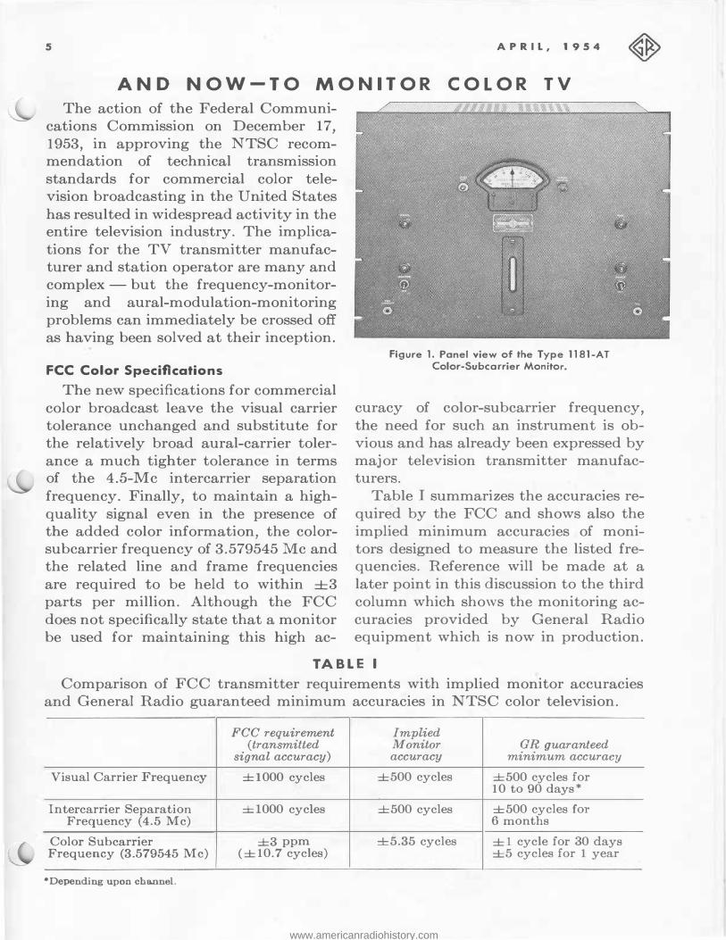
AND NOW-TO MONITOR COLOR TV
The action of the Federal Communi
cations Commission on December 17,
1953, in approving the NTSC recommendation of technical transmission
standards for commercial color television broadcasting in the United States
has resulted in widespread activity in the entire television industry. The implica
tions for the TV transmitter manufacturer and station operator are many and
complex -but the frequency-monitor
ing and aural-modulation-monitoring
problems can immediately be crossed off
as having been solved at their inception.
FCC Color Specifications
The new specifications for commercial
color broadcast leave the visual carrier
tolerance unchanged and substitute for
the relatively broad aural-carrier toler
ance a much tighter tolerance in terms of the 4.5-Mc intercarrier separation
frequency. Finally, to maintain a high
quality signal even in the presence of the added color information, the colorsubcarrier frequency of 3.579545 Mc and the related line and frame frequencies
are required to be held to within ±3 parts per million. Although the FCC
does not specifically state that a monitor
be used for maintaining this high ac-
Figure 1. Panel view of tile Type 1181-AT Color-Subcarrier Monitor.
curacy of color-subcarrier frequency,
the need for such an instrument is ob
vious and has already been expressed by major television transmitter manufacturers.
Table I summarizes the accuracies re
quired by the FCC and shows also the
implied minimum accuracies of monitors designed to measure the listed frequencies. Reference will be made at a
later point in this discussion to the third
column which shows the monitoring ac
curacies provided by General Radio equipment which is now in production.
TABLE I
Comparison of FCC transmitter requirements with implied monitor accuracies
and General Radio guaranteed minimum accuracies in NTSC color television.
FCC requirement Implied (transmitted Monitor GR guaranteed
signal accuracy) accuracy minimum accuracy
Visual Carrier Frequency ±1000 cycles ±500 cycles ±500 cycles for 10 to 90 days*
Intercarrier Separation ±1000 cycles ±500 cycles ± 500 cycles for Frequency (4.5 Mc) 6 months
Color Subcarrier ±3 ppm ±5.35 cycles ± 1 cycle for 30 days Frequency (3.579545 Mc) (±10.7 cycles) ±5 cycles for 1 year
•Depending upon channel.
www.americanradiohistory.com

GENER AL R ADI O EXPERIMENTER 6
Station Monitor Performance -
Black-and-White vs Color
The TYPE 1183-T TV Station Monitor has been in full production for well over a year, and more than three hundred are now in operation with blackand-white transmitters in the United
States and abroad. In this service, the monitor is required to provide accuracies of ±500 cycles on indication of visualtransmitter carrier frequency and ±2000 cycles on indication of aural-transmitter center frequency. Actually, when an appropriate frequency-checking schedule
is followed for the visual carrier, the maximum error in the aural monitor is less than ±1000 cycles per year.
The deviation of the intercarrier sepa
ration frequency from 4.5 megacycles is given by the algebraic difference of the indications of the aural- and visual-carrier deviation meters.
It will be recalled by users of the Station Monitor that its circuit design utilizes a single master reference crystal for both of these functions. Any error in the determination of intercarrier cl.eviation is therefore independent of this crystal and is almost completely determined by the stabilities of the meter
ing circuits used in the aural and visual monitors. The former is better than ±200 cycles and the latter better than ±100 cycles for any thirty-day period. The maximum instability of relative frequency indication that can result is less than ±300 cycles for a comparable period.
Further, experience over much longer periods of time shows that the relative
indications will provide a measure of
intercarrier separation frequency to better
than ±500 cycles for a period of at least
six months. This is not at all surprising when it is realized that meter and metering circuit instabilities are of a random
nature and do not normally produce a progressive drift in any one direction.
Time-honored Monitor - New Applica
tion to Subcarrier Monitoring
The new TYPE 1181-AT Color Subcarrier Monitor is an adaptation of the universally employed and widely acclaimed TYPE 1181-A A-M Frequency Deviation Monitor, about 1400 of which are now in service in a-m broadcasting stations. This monitor provides a de
viation range of ±30 cycles with onecycle divisions and affords a stability of better than one part per million when used in the frequency range from 500 to 2000 kilocycles. Except for this frequency-range limitation, the A-M Fre
quency Deviation Monitor is adequate without modification for service as a color subcarrier monitor.
A high-stability plated quartz crystal developed by the Bell Telephone Laboratories a few years ago has been a major factor in the success of the TV Station Monitor. On the premise that colortransmitter engineers will want to avail themselves of as much of the 3-ppm tolerance on the color subcarrier as they can, the General Radio monitor-engineering group has built this crystal into the new TYPE 376-Q Crystal Assembly. Substitution of this assembly, adjusted for monitoring 3.579545 Mc, in place of the older TYPE 376-L Quartz Plate - without further change in the circuits of the instrument - resulted in immediate satisfactory performance, and subsequent long-time checks permit stability ratings of ± 1 cycle for thirty days and ±5 cycles for one year.
The monitor incorporating the TYPE 376-Q Crystal Assembly has been identified as the TYPE 1181-AT Color Subcarrier Monitor. A TYPE 274-ND Shielded Plug is supplied for coupling to the color-
www.americanradiohistory.com

7
subcarrier source in the transmitter through a suitable length of shielded cable. All of the desirable features of the original A-M Monitor are retained. Some of these are : (1) Ability to operate on input signals
ranging from 10 mv to 1 volt; (2) High noise rejection in narrow-band
i-f system; (3) Performance unaffected by ampli
tude modulation whether extraneous or otherwise;
(4) Panel adjustment of frequency deviation indication to bring monitor into agreement with independent frequency measurements;
(5) Panel lamp indication of failure of monitor input signal;
(6) Remote metering facilities. To sum up, the combination of the
TYPE 1183-T TV Station Monitor and the TYPE 1181-AT Color Subcarrier Monitor provides complete facilities well within the latest requirements of the Federal Communications Commis-
APRIL, 1954
sion for monitoring the frequencies involved in commercial color-television transmissions. Comparison of the second and third columns of Table I shows that minimum guaranteed stabilities suggest the need for: (1) Independent frequency measure
ment of the picture carrier frequency at intervals ranging from ten days for Channel 83 to over three months for Channel 2;
(2) Concurrent measurement of the sound carrier or intercarrier separation no more frequently than once in six months regardless of channel;
(3) Independent measurement of the color subcarrier about once a year.
All of these periods represent minimum requirements compatible with guaranteed accuracy, and experience on the part of the opera tor will in most instances permit his extending the interval between frequency checks markedly after the equipment has been in service some time.
-W. R. SAYLOR
M AY-MONTH OF EXHIBITS
The month of May will find General Radio engineers setting up exhibits of equipment in many parts of the country. If you attend any of the various meetings and conferences listed below, we hope that you will drop in to see the General Radio display and to talk over your measurement problems with General Radio engineers.
NEW ENGLAND
R ADIO ENGINEERING MEETING
Hotel Sheraton Plaza - Boston
May 7 and 8
Sponsored by the North Atlantic Region of the Institute of Radio Engineers, the NEREM was the first of the regional IRE annual meetings. The
Seventh Annual Meeting this year is a two-day affair with a well-balanced technical program. General Radio will be there in Booths 40 and 41.
NATIONAL CONFERENCE
ON AIRBORNE ELECTRONICS
Dayton Biltmore Hotel - Dayton, Ohio
May 10- 12
This annual conference, sponsored jointly by the Dayton Section of the IRE and the Professional Group on Airborne Electronics, has for its motto "Electronics -the Key to Air Supremacy." General Radio will be in Booth 11-A, as in previous years. Engineers in attendance will be Frank D. Lewis, Robert E. Bard, Kipling Adams, and William M. Ihde.
www.americanradiohistory.com

GENERAL RADIO EXPERIMENTER 8
SY M POSIU M ON INDUSTRIAL
HY GIENE INSTRU MENTATION
University of Michigan
Ann Arbor, Michigan - May 24-2 7
The purpose of this Symposium, conducted by the School of Public Health and the Institute of Industrial Health of the University of Michigan, is to present what is known, what is available, and what is needed in instrumentation for industrial hygiene through the medium of exhibits, discussions, comprehensive reviews, and technical papers. Here, the General Radio Company will exhibit its complete line of sound-measuring equipment, as well as other items of interest to industrial hygienists. Ervin E. Gross, Jr., of our development staff at Cambridge and WilliamM. Ihde from our Chicago office will be in attendance.
equipment will be held in the main Clinical Building on these dates. Drop in to see us at Booth 16. General Radio engineers in attendance will be Myron T. Smith, Robert J. Caldwell, and John C. Gray.
IRE SEVENT H REGIONAL
TEC HNICAL CONFERENCE
Multnomah Hotel - Portland , Oregon
May 5- 7
General Radio will participate in the show held in conjunction with the conference. On hand to greet you will be Frederick Ireland of our Los Angeles office.
INSTRU MENT SOCIETY OF
A MERICA
SEATTLE SECTION MEETING
May 19-20
NATIONAL INSTITUTES OF HEALT H Frederick Ireland of our Los Angeles
Bethesd a, Maryland - May 24-2 7 office will exhibit a group of General The fourth annual exhibit of research Radio instruments at this meeting.
DELIVERIES ARE GOOD
Of the 175 major type categories listed in our latest general catalog, 171 are available for immediate delivery. Of the remainder, only 4 are temporarily backordered for delivery longer than 30 days. They will be in stock soon after that.
The TYPE 1000-P7 Balanced Diode Modulator, described in this issue, a new and especially interesting instrument, is available in limited quantities now -many more are in process for stock delivery this summer.
GENERAL RADIO COMPANY
SINCE 1915-MANUFACTURERS OF ELECTRONIC APPARATUS FOR SCIENCE AND INDUSTRY
275 MASSACHUSETTS AVENUE CAMBRIDGE 39 MASSACHUSETTS
TELEPHONE: TRowbridge 6-4400
BRANCH ENGINEERING OFFICES NEW YORK 6, NEW YORK
90 WEST STREET
TEL.-WOrth 4·2722
LOS ANGELES 38, CALIFORNIA
1000 NORTH SEWARD STREET
TEL-HOiiywood 9·6201
CHICAGO 5, ILLINOIS
920 SOUTH MICHIGAN AVENUE
TEL.-WAbash 2-3820
www.americanradiohistory.com