n hoses and fittings n air treatment n accessories · selection guide n hoses and fittings n air...
TRANSCRIPT
www.kremlin-rexson.com
Selection guiden Hoses and Fittings
n Air Treatmentn Accessories


Hoses and Fittings Air Treatment
Accessoires
EditorialEditorial
KREMLIN REXSON are delighted to present the product selection guide for Hoses and Fittings, Air Treatment and Accessories.
KREMLIN REXSON received the ISO 9001 certification accredited by LRQA for the design and manufacture of its range of paint application equipment. All equipment are ATEX compliant.
An energetic Research and Development policy has given KREMLIN REXSON the ability to provide the best solutions for most applications in the metal, wood, plastic and automotive markets leading to significant reductions in VOC emissions.
KREMLIN REXSON products are designed with two objectives :
- to continuously innovate equipment to meet the needs of all new coating systems arriving in the market (water-based, high-
solids, etc)- to reduce operating costs whilst meeting new environmental concerns.
The quality of KREMLIN REXSON equipment is recognized worldwi-de, a statement which is borne out by the fact that 75% of its sales are exported. This powerful interna-tional presence allows KREMLIN REXSON to quickly respond to emerging market needs by deve-loping innovative new equipment.
Our new interactive product selection guide will help you to select, the best, the right equipment and use it to its highest potential.
Please do not hesitate to contact your local distributor or a KREMLIN REXSON technical advisor.
They are there to help you find the best solution for all your needs.

2
SummarySummary
3
10
12
13
20
21
22
24
24
27
29
30
32
Practical pages
Fluid hoses
Air hoses
Hose fittings
Quick fiftings
Valves
Filtration
Fluid Regulator - low pressure
Constant Flow™
Fluid Regulator-medium pressure
Air regulator
Air treatment
Accessories

3
PRACTICAL PAGESPRACTICAL PAGES
To optimizen For the best pump capacity, first work out the output you are going to require. This will include the sprayguns
themselves, and any circulation you plan to have within this system. Once you have this figure, multiply by 1.2, and then choose the pump of which output at 30 cycles per minute is the nearest.
n The compression ratio you will need is defined by the pressure losses due to the length and diameter of the hosing of your system. To calculate these pressure losses, see page 4.
Examplelet say you want to feed 3 conventional guns with an output of 500 cc/mn each, plus a circulation of 0,5 l/mn.The total output will thus be 2 l/mn. The optimal pump capacity would be: (2 000 x 1,2) ÷ 30 = 80 cc/cycle.The best-suited pumps will be:
n the PMP 150 (output of 100 cc/cycle and pressure ratio of 1:1) for low viscosity materials and a small circulating (pressure loss < 3 bar).
n the 02.75 (output of 85 cc/cycle and pressure ratio of 2:1) for thicker materials and a normal circulating (pressure loss < 6 bar).
n the 04.120 (output of 240 cc/cycle and pressure ratio 4:1) for large pressure loss in circulating (up to 15 bar).
MeshMicron
N° filtre (number of holes in 25,4 mm) (mesh opening in m)
10 1480 –
16 975 –
20 750 30
25 630 25
30 500 20
40 375 –
45 360 15
50 300 12
60 238 –
70 210 8
80 175 6
100 149 –
140 100 4
170 90 3
200 74 –
250 60 –
270 50 2
325 40 1
400 35 –
Filtration equivalencePump Material FeedingTo guarantee the right delivery of product,
we offer the following range of equipment for
various product viscosity:
n 0 - 300 cps
n suction rod.
n 300 to 8 000 cps
n top outlet pressure pots,
n pumps (gravity or suction rod),
n pump with base intake valve.
n 8 000 to 15 000 cps
n bottom outlet pressure pots,
n pumps with suction rods,
n compressor.
n 15 000 to 30 000 cps
n no more pressure pot,
n no more suction rod,
n submerged hydraulic pump,
n compressor,
n pump with single action elevator.
n 30 000 à 1 000 000 cps and +
n pumps with peak feeder and double
action elevator.

4
PRACTICAL PAGESPRACTICAL PAGES
Pressure loss in fluid hoses
For product of different viscosities, multiply the pressure loss by the viscosity in Cps.
300
Pressure drops in milibar / meter of hose and f or a viscosity of 1 centipose
Fluid owr ate ( l/mn )
1
0,06
1
0,12
2
0,18
3
0,24
4
0,3
5
0,42
7
0,6
10
1,2
20
1,8
30
3
507
23
1/8''
471020 5
3/161/4''3/4''1
2001007050302010764 5321
Fluid owr ate ( cm /sec )
Ø hose ( ’ ’ )
Ø hose (mn )
3
Loss of pressure
Air output (m3/h)10
0,04
0,1
0,2
0,3
0,2
0,5
1
1,5
20 30 40 50
per metre(bar/m)
hose Ø 5
hose Ø 7
hose Ø 10
hose Ø 16
for 5m hose(bar/5m)
hose Ø 8
(m3/h)
Use : Look up the paint output on the lower scale. Look up the hose diameter on the middle scale. Join these two points together, extend the line and read te pressure loss on the upper scale. Finally, adjust this figure for the correct viscosity to determine the pressure loss in millibars per meter of hose.
Example :AIRLESS tip of 30Output : 2,4lØ hose 1/4’’Pressure loss 13 millibar/mFluid of 30 centipoises = 13 x 30 = 390

5
Correspondence between accepted measures of viscosityViscosity is very susceptible to changes in temperature. It should be measured at the same temperature as that which will be prevalent during the application.
Electrostatic spraying : suitability of the equipment depending on the resistivity of the paints.
n the wrap-around affect is optimized with paints of resistivity range of 5 - 50 M .cm..
n Specific hoses allows for wrap-around effects for resistivity range higher than 2M cm.
n For water-based materials (0 M .cm), a special ISObubble enclosure allows to benefit from all the advantages of electrostatic spraying in complete safety.
On the Kremlin resistivometer, resistivity can be read directly on the display.
AFNOR 4 (CA4) ISO 4 mPas.s Centipoises Ford 4 (CF4) DIN 4 (D°) LCH (Fr) ZAHN (n°2)
12 — 20 20 10 11 6 18
14 17 25 25 12 12 7 19
16 23 30 30 14 14 — 20
20 34 40 40 18 16 8 22
25 51 50 50 22 20 9 24
29 60 60 60 25 23 10 27
32 68 70 70 28 25 — 30
34 74 80 80 30 26 11 34
37 82 90 90 33 28 12 37
40 93 100 100 35 30 13 41
45 — 120 120 40 34 14 49
50 — 140 140 44 38 15 58
56 — 160 160 50 42 16 66
61 — 180 180 54 45 17 74
66 — 200 200 58 49 18 82
70 — 220 220 62 52 19 —

6
PRACTICAL PAGESPRACTICAL PAGES
Example : For a temperature of 20°C, for a recommended viscosity of 22 s.
You should adapt the viscosity as follows :
- at 12°C, a paint of 28 s, - at 32°C, a paint of 17 s.
temperatures (°C)
v
i
s
c
o
s
i
t
y
i
n
s
e
c
o
n
d
s
C
F
4
2° 4° 6° 8° 10° 12° 14° 16° 18° 20° 22° 24° 26° 28° 30° 32° 34° 36° 38° 40°
27 26 24 23 22 21 21 20 19 18 18 17 17 16 15 15 14 14 14 14
33 31 29 27 26 25 23 22 21 20 19 18 18 17 16 16 15 15 14 14
39 36 34 32 30 28 26 24 23 22 21 20 19 18 17 17 16 15 15 14
46 42 39 36 34 31 29 27 26 24 23 22 21 19 18 17 17 16 15 15
54 49 45 41 38 35 32 30 28 26 24 23 21 20 19 18 17 17 16 15
58 51 47 43 40 36 33 31 29 27 25 23 21 20 20 19 18 17 16 16
61 55 50 46 42 38 35 32 30 28 26 24 22 21 20 19 18 17 16 16
69 63 56 52 46 42 39 35 32 30 28 25 24 23 21 20 19 18 17 16
77 69 62 55 50 46 41 38 35 32 29 27 25 24 22 21 19 18 17 16
84 74 67 61 54 50 44 40 36 34 30 28 26 25 23 22 20 18 17 16
95 84 75 66 60 54 48 44 40 36 33 30 28 26 24 22 20 19 18 17
104 92 81 73 65 58 52 46 42 38 35 31 29 27 24 23 21 20 19 18
112 100 88 76 69 62 54 49 44 40 36 32 30 27 25 23 21 20 19 18
122 108 90 85 75 66 59 53 47 42 38 35 31 28 26 24 22 21 19 18
132 120 102 90 80 70 63 55 50 44 40 36 33 30 27 25 23 22 20 18
142 124 108 95 84 74 65 58 52 46 41 37 34 31 27 25 23 22 20 18
152 132 119 101 90 80 69 61 54 48 43 38 35 31 28 26 24 23 21 18
164 140 123 106 94 83 73 64 56 50 45 40 36 32 29 27 24 23 21 19
Table showing the effect of temperature on fluid viscosity - solvent-based paints

7
Conversion of metric units to imperial and vice-versa
List showing the compressed air consumption of normal air toolsWe generally multiply the instant consumption by a coefficient of 0,5 to 0,9 to allow for the time the tool is not in use.
The average air volume delivered by a compressor of 1 CV is of 8 m3/h.
Calculate exactly the maximum air consumption of pump in l/mn : Q
The formula is :Q = 1,2 x fluid output x pressure ratio x (air motor feeding pressure in bar + 1 bar for atmosphere)
Example for a pump 16.120 : Q = 1,2 x 4,8 x 16 x (6 + 1) = 645,12 l/mn or (645,12 x 60) : 1000 = 38,7 m3/h
Tool l/mn m3/h
Projection equipment 800 at 1 800 48 at 108
Riveter 450 at 1 500 27 at 90
Pneumatic drill 600 at 1 200 36 at 72
Linisher Ø 230 1 200 at 4 000 72 at 240
Drill 13 mm 600 36
Rotating sander 200 at 400 12 à 24
Consumption
Tool l/mn m3/h
KREMLIN conventional gun 160 at 500 10 at 30
AIRMIX® gun 67 at 134 4 at 8
KREMLIN pumps 160 at 1 350 10 at 80
Blower 200 at 400 12 at 24
Screwdriver 200 at 400 12 at 24
Measurement English unit Metric unit relationship Name Abreviation Name Abreviation English Metric Metric English
Length inch in or ‘’ micron 1 in = 25 400 1 m = 0,03937x10⁻³in
inch in or ‘’ millimètre mm 1 in = 25,4 mm 1 mm = 0,03937 in
inch in or ‘’ centimètre cm 1 in = 2,54 cm 1 cm = 0,3937 in
inch in or ‘’ mètre m 1 in = 0,0254 m 1 m = 39,37 in
foot ft or ‘ mètre m 1 ft = 0,304 m 1 m = 3,2808 ft
yard yd mètre m 1 yd = 0,914 m 1 m = 1,0936 yd
Area square inch sq. in millimètre carré mm2 1 sq. in = 645,16 mm2 1 mm2 = 0,00155 sq. in
square inch sq. in centimètre carré cm2 1 sq. in = 6,4516 cm2 1 cm2 = 0,155 sq. in
square foot sq. ft mètre carré m2 1 sq. ft = 0,0929 m2 1 m2 = 10,7639 sq. ft
Volume cubic foot cu. ft litre/décimètre cube l/dm3 cu. ft = 28,317 dm3 1 l = 0,03531 cu. ft
cubic foot cu. ft mètre cube m3 cu. ft = 0,0283 m3 1 m3 = 35,314 cu. ft
gallon impérial gal litre l 1 gal = 4,546 litres 1 l = 0,2199 gal
gallon américain US gal litre l 1 US gal = 3,785 litres 1 l = 0,2642 US gal
Output cubic foot per minute c.f.m. mètre cube par heure m3/h 1 c.f.m. = 1,699 m3/h 1 m3/h = 0,5886 c.f.m.
Weight pound lb gramme g 1 lb = 453,59 g 1 g = 2,204 x 10–3 lb
pound lb kilogramme kg 1 lb = 0,454 kg 1 kg = 2,204 lb
Pressure pound square inch p.s.i. bar bar 1 p.s.i. = 0,068 bar 1 bar = 14,503 p.s.i.
Electrical Power horse power HP cheval ch 1 HP = 1,0139 ch 1 ch = 0,9863 HP
horse power HP kilowatt kW 1 HP = 0,7457 kW 1 kW = 1,3411 HP
Thermal energy British Thermal Unit/hourBtu. hr Kilocalorie par heure kcal/h 1 Btu. hr = 0,2520 kcal/h 1 kcal/h = 3,968 Btu. hr
Speed foot per second ft/sec mètre par seconde m/s 1 ft/sec = 0,304 m/s 1 m/s = 3,2808 ft/sec
Temperature degree fahrenheit °F degré centigrade °C 1 °F = (1,8°C) + 32 1°C = (°F - 32) x 0,555
Heat British Thermal Unit Btu. kilocalorie kcal 1 Btu. = 0,2520 kcal 1 kcal = 3,968 Btu.
British Thermal Unit Btu. thermie th 1 Btu. = 0,252 x 10–3 th 1 th = 3968 Btu.
British Thermal Unit Btu. Joule J 1 Btu. = 1055 J 1 J = 0,9473 x 10⁻³Btu.

8
Main everyday solvents
PRACTICAL PAGESPRACTICAL PAGES
(1) CF = closed dish ; CO = open dish.(2) these values were established by American hygenists corresponding to 7-8 h/day and a 40 h/week.
(3) p.p.m. = parts per million, by volume.(4) Delivered from coal.
(Extract from n°103 INRS brochure.)
Properties of products Boiling Flash point Explosive limit in vol. %Temperature (°C) (°C) (CF) (1)
Amyle acetate 149 25 1,1 7,5 100 525
Butyle acetate 124-126 23 1,7 15 150 710
Dry butyle acetate 112 31 (CO) 1,7 — 200 950
Ethyle acetate 77,1 – 4,4 2,2 11,5 400 1 400
Ethylglycol acetate 156,4 52 1,7 5,8 100 540
Isopropyle acetate 93 4,4 1,8 8 250 950
Methyle acetate 57-58 – 13 3,1 16 200 610
Acetone 56,2 – 18 2,5 12,8 1 000 2 400
Amylic alchohol 137,8 33 1,2 10 — —
Butylic alchohol 117,5 29 1,4 11,2 100 300
Dry butylic alchohol 99,5 24 1,7 9,8 150 450
Ethylic alchohol 78,5 13 3,3 19 1 000 1 900
Isopropylic alchohol 82,4 12 2 11,8 400 980
Methylic alchohol 65 12 6 36,5 200 260
Benzene 80,1 – 11 1,4 8 25 80
Butylglycol 171743 60 1,1 10,6 50 240
Cyclohexane 81 – 20 1,3 8,3 300 1 050
Cyclohexanol 161 68 1,8 — 50 200
Cyclohexanone 156 44 à 64 1,3 9,4 50 200
Diacetone alchohol 168 54-55 1,8 6,9 50 240
Dioxane 1-4 101 12,2 2 22 100 360
Terebenthine essence 154-170 35 0,8 — 100 560
Special essences 30-210 4 1 6,5 — —
Ethylglycol 135 40 2,6 15,7 100 370
Methyléthylcetone 79,6 – 6 1,8 11,5 200 590
Methylisobutylcarbinol 130 41 1 5,5 25 100
Methylisobutylcetone 116 16 1,4 7,5 100 410
Methylglycol 125768 46 2,5 14 25 80
Naphta solvent(4) 125-160 23 à 32 0,9 6 100 400
Styrene 146 31 1,1 6,1 100 420
Tetrahydrofuranne 64-66 – 17 2,3 11,8 200 590
Toluene 110,6 4,4 1,3 7 100 375
Trichlorethylene 87 non-flammable — — 100 535
White spirit 135-205 30 à 65 1,1 6,5 200 1 150
o-Xylene 144 30 1 6 100 435
lower upperToxicity limit of concentration in the air (2) P.P.M. (3) mg/m3

9
ACID NEUTRAL BASIC
00 01 02 03 04 05 06 07 08 09 10 11 12 13 14
Value of «PH»The pH value of a liquid or a solution quantifies its concentration of hydrogen ions and tells us the extend to which it is acidic or alkaline. The PH value dictates the best materials to be used in construction of major paint handling and spraying equipment.
Stainless Steel316
Corrosion-resistant(stainless-steel 303)
Standard orstainless steel
Corrosion-resistant(stainless steel 303)
Stainless Steel316

10
HOSE FOR SUCTION ROD
ADAPTATION KIT FOR EQUIPMENT FITTED WITH 14X125 AND 18X125
HOSES CONFIGURATION
Flu
id h
ose
sF
luid
ho
ses
● Conventional and low pressure spraying.
A hose carrying paint must be able to resist all solvents. For conventional spraying, Kremlin offers two types of hose : ● Very supple, special paint nitrile rubber, with red casing. ● White polyamide : when the paint is thicker, to reduce pressure losses.
Designation Part numberMaterial Nitrile rubber Polyamide(1)
Internaldiameter mm 7 10 16 6,35 (1/4") 9,52 (3/8")
Maximumpressure : bar 10 7 10
Color red strip white stripTemperature up to 60 °C
P.N. without fitting 5 m
050.362.004-
050.361.005-
050.363.005-
050.370.805-
050.370.905-
P.N. without fitting 15 m
050.362.003-
050.361.004-
050.363.004-
050.370.804-
050.370.904-
P.N. without fitting 25 m
050.362.001-
050.361.001-
050.363.001-
050.370.801-
050.370.901-
P.N. without fitting 100 m
050.362.002-
050.361.002-
050.363.003-
050.370.803-
050.370.903-
SK collar906.311.224
-906.311.226
-906.311.207
-- - -
Lengths with fittings part number
A and B fitting(free nut)
1/4" NPS 3/8" NPS -- 1/4" NPS 3/8" NPS
1m050.362.451
--
050.361.108-
- - - -
2 m - - - - - -050.370.504
-
5 m050.362.101
-050.362.603
-050.361.105
--
050.370.301-
050.370.201-
050.370.502-
7,5 m050.362.104
-050.362.601
-050.361.102
-- - - -
Description Part numberPack of 2 fittings M1/4"NPS - F14x125 150.123.535Pack of 2 fittings M3/8"NPS - F18x125 150.123.610
(1) Recommended for glues
● Hose for suction rodDesignation Part numberPolyethylenehose sleeve Ø 9.5 mm Ø 19 mm Ø 25 mm
5 m cut 050.368.001 050.366.051 050.367.00115 m cut 050.368.002 050.366.052 -25 m cut 050.368.003 050.366.053 050.367.003Groovedconical fitting 050.140.517 050.140.545 050.140.543
Nickeled nut fitting 050.271.303(1) 050.271.502(2) 049.595.306(3)
Wing collar 906.311.234 906.311.207 906.311.204
(1) F 18 x 125(2) F 26 x 125(3) F 38 x 150
A
B

11
● AIRMIX® and AIRLESS spraying ● The hoses should be chosen according to the pressure used in the application and electrical conductibility A
B
HOSES CONFIGURATIONDesignation Part number Part numberHose AIRMIX® High pressure Very high pressureConductive NO YESColor GREY BLUE BLACKInternaldiameter mm 3,2 4,8 6,35 3.2 4,8 6,35 9,52 6,35 9,52
Max.operatingpressure bar
120 240 225 450 375
Temperature up to 100°C
25 m050.450.059
-050.450.060
-050.450.070
-- -
050.450.005-
- -
100 m050.450.061
-050.450.071
-- - - - - -
300 m050.450.064
-050.450.072
-- - - - - -
Fitting alone to crimp
905.063.304-
905.063.305-
- - - - - -
Fitting alone to screw in -
905.063.308-
905.063.309-
- - -905.060.107
-- -
Fitting alonestainlesssteel to crimp
905.063.359-
905.063.354-
905.063.355-
- - - - - -
Fitting alone stainlesssteel to screw in
905.063.356-
905.063.358-
905.063.357-
- - - - - -
Spring for fitting to crimp
905.063.361-
- - - - - -
PART NUMBER ACCORDING TO LENGTH WITH FITTINGS per meter
A and B fittings(free nut)
1/2 JIC 3/4 JIC 1/2 JIC 3/4 JIC
Treated Stainless Steel Fittings
With spring Withoutspring With spring Without
springWithoutspring
Withoutspring
Withoutspring
0,6 m-1,92ft050.450.805
-050.450.701
-050.450.106
-
0,8 m-2,56ft050.450.702
-050.450.107
-
1 m-3,2ft050.450.809
-050.450.703
-050.450.601
-050.450.102
-050.451.001
-050.450.905
-
2 m-6,4ft050.450.806
-050.450.704
-050.450.602
-050.450.109
-
3 m-9,6ft050.450.810
-050.450.705
-050.450.603
-050.450.110
-050.450.904
-
5 m-16ft050.450.801
-050.450.706
-050.450.604
-050.450.108
-050.451.002
-050.450.903
-
7,5 m-24ft050.450.808
-050.450.605
-050.450.111
-
10 m-32ft050.450.802
-050.450.707
-050.450.606
-050.450.104
-050.451.003
-050.450.902
-
15 m-48ft050.450.811
-050.450.709
-050.450.607
-050.450.112
-
20 m-64ft050.450.812
-050.450.708
-050.450.608
-050.450.105
-050.450.901
-
25 m-80ft050.450.113
-Stainless Steel Fittings
0,6 m-1,92ft050.450.851
-050.450.651
-
1m/3'050.451.151
-
5 m-16ft050.450.852
-050.451.152
-050.450.652
-050.450.152
-
7,5 m-24ft050.450.853
-050.451.153
-050.450.653
-050.450.153
-
Flu
id h
ose
sF
luid
ho
ses

12
HOSES CONFIGURATION
ADAPTATION KIT FOR EQUIPMENT FITTED WITH 14 TO 26X125 FITTINGS
HOSES CONFIGURATION
● Nitrile conductor hoses - green band
To use so that the equipment (gun and pump) have the same potential
Designation Part numberInternaldiameter(mm)
7 8 10 16
Color Gold Green White BlueMaximumpressurebar/psi
10/145
P.N. 5mwithoutfitting15m
050.382.005 050.389.004 050.381.005 050.383.005
050.382.004 050.389.003 050.381.004 050.383.004
P.N. 25mwithoutfitting
050.382.001 050.389.001 050.381.001 050.383.001
P.N. 100m-320ftwithoutfitting
050.382.002 050.389.002 050.381.002 -
Collar SK 906.311.224 906.311.224 906.311.226 906.311.232
Part number according to length with fittings
Fitting A B
1/4 NPS1/4 NPS
3/8 NPS3/8 NPS
P.N. with fittings 5m-16ft
050.382.109 050.389.101 050.381.101 -
7,5 m 050.382.114 050.389.103 - -10 m 050.382.110 050.389.102 050.381.102 -15 m 050.389.105
Description Part numberPack of 2 fittings M1/4"NPS - F14x125 150.123.535Pack of 2 fittings M3/8"NPS - F18x125 150.123.610Pack of 2 fittings M3/4"NPS - F26x125 150.123.611
● Special hoses
Designation Part numberMaterial Polyamide PolyurethanColor translucent black tranclucent blue blackInternaldiameter(mm)
2,7 x 4 4 x 6 6 x 8 6 x 8 8 x 10 4 x 6 6 x 8 8 x 12
Conductive NoMaximumoperatingpressurebar/psi
10/145
Temperature up to 60 °CP.N. without fittings : per meter
539.090.101-
539.090.115 -
539.090.102-
539.090.701-
539.090.103-
539.280.101-
539.280.102-
539.310.101-
25 m -050.371.001
-050.371.002
-- - - - -
5 m - - - - - -050.380.200
--
7,5 m - - - - - -050.380.250
--
A
B
Air
ho
ses
Air
ho
ses

13
● PTFE Airmix® and Airless hoses
HOSES CONFIGURATIONDesignation Part numberMaterial color Grey with metallic braidInternaldiameter (mm) 6,35 (1/4") 10 13 (1/2")
Conductive ● ● ●
OperatingpressureMaximum barMaximum psi
2503625
1752538
3505075
Temperature + 10 °C to + 150 °CFittingsA
B (free nut)
1/2 JIC1/2 JIC
3/4 JIC3/4 JIC
3/4 JIC3/4 JIC
P.N. with fittings 0,70 m - 050.451.904 -
1m 050.452.001 050.451.903 -2 m - 050.451.901 050.452.2045 m 050.452.002 050.451.902 -7 m - - 050.452.20110 m - - 050.452.203
● Fittings for low pressure air and fluid rubber hoses
For all products, particularly those which are sensitive to air humidity (like silicone) and those which are chemically aggressive.
FITTINGS CONFIGURATION
Thread size Material Hoses Inter. Diameter (mm) Part number Collar
M 14 x 125 Nickel plated brass 7 050.230.605 906.311.2241/4" NPS Nickel plated brass 7 050.231.705 906.311.224M 14 x 125 Nickel plated brass 8 050.230.607 906.311.2241/4 NPS Nickel plated brass 8 050.231.707 906.311.224M 14 x 125 Nickel plated brass 10 050.230.602 906.311.2261/4 NPS Nickel plated brass 10 050.231.702 906.311.226M 14 x 125 Nickel plated brass 5 050.230.604 906.311.224M 14 x 125 Stainless steel 5 050.230.610 906.311.208M 18 x 125 Nickel plated brass 7 050.230.616 906.311.2243/8 NPS Nickel plated brass 7 050.231.716 906.311.224M 18 x 125 Nickel plated brass 10 050.230.606 906.311.2263/8 NPS Nickel plated brass 10 050.231.706 906.311.226M 18 x 125 Nickel plated brass 16 050.230.601 906.311.2323/8 NPS Nickel plated brass 16 050.231.701 906.311.232M 18 x 125 Stainless steel 10 050.230.614 906.311.226M 26 x 125 Nickel plated brass 16 050.230.603 906.311.232M 35 x 150 Nickel plated brass 25 - 906.311.213M 14 x 125 Nickel plated brass 5 050.250.204 906.311.208M 14 x 125 Nickel plated brass 7 050.250.203 906.311.224M 18 x 125 Nickel plated brass 10 050.250.202 906.311.226
Nickel plated brass 7 050.190.403 906.311.224Nickel plated brass 10 050.190.401 906.311.226
Flu
id h
ose
sF
luid
ho
ses
Ho
se f
itti
ng
sH
ose
fit
tin
gs
A
B

14
FITTINGS CONFIGURATION
● Fittings for low pressure polyamide hoses
Thread size Material Hoses Inter. Diameter (mm) Part number
M 3/8" NPS NIckel plated brass 6.35 - 1/4 050.231.350M 1/4" NPS NIckel plated brass 6.35 - 1/4 050.231.450M 3/8" NPS NIckel plated brass 9.52 - 3/8 905.140.103
● Fittings for special air hosesFITTINGS CONFIGURATIONC D Straight Right angle 90° T- piece
G 1/8 (5 x 10) BSP4 905.120.907 905.120.926 -6 - 905.120.902 -8 - 905.120.934 -
G 1/4 (8 X 13) BSP4 905.120.927 -6 905.120.965 905.120.905 -8 905.120.904 905.120.912 905.120.920
6 x 8 hose T 2,7 x 4 Hose T- piece 4 x 6/2,7 x 4 Reduction T- piece
905.120.915 905.120.957 905.120.928
Te
T for hose
T for reduction
D
C C
D
Straight Elbow 90°
C
D
Ho
se f
itti
ng
sH
ose
fit
tin
gs
15
FITTINGS CONFIGURATION
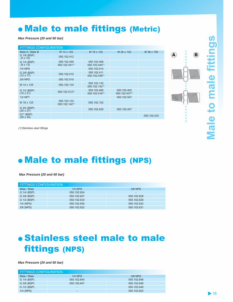
● Male to male fittings (Metric)Max Pressure (20 and 60 bar)
Male A / Male B M 14 x 125 M 18 x 125 M 26 x 125 M 38 x 150G 1/8 (BSP) (5 x 10) 050.102.412
G 1/4 (BSP) (8 x 13)
050.102.405 050.102.441(1)
050.102.408 050.102.444(1)
1/4 NPS 050.102.514
G 3/8 (BSP) (12 x 17) 050.102.410
050.102.411 050.102.436(1)
3/8 NPS 050.102.519
M 14 x 125 050.102.134 050.102.133
050.102.142(1)
G 1/2 (BSP) (15 x 21) 050.102.513(1) 050.102.406
050.102.418(1)
050.102.402 050.102.437(1)
1/2 NPT 050.102.507
M 18 x 125 050.102.133
050.102.142(1) 050.102.102
G 3/4 (BSP) (20 x 27) 050.102.429 050.102.407
G1" (BSP) (26 x 34) 050.102.433
(1) Stainless steel fittings
● Male to male fittings (NPS)
Max Pressure (20 and 60 bar)
FITTINGS CONFIGURATION
FITTINGS CONFIGURATIONMale / Male 1/4 NPS 3/8 NPSG 1/4 (BSP) 050.102.624 -G 3/8 (BSP) 050.102.627 050.102.628G 1/2 (BSP) 050.102.633 050.102.6291/4 (NPS) 050.102.630 050.102.6323/8 (NPS) 050.102.632 050.102.631
● Stainless steel male to male fittings (NPS)
Max Pressure (20 and 60 bar)
Male / Male 1/4 NPS 3/8 NPSG 1/4 (BSP) 050.102.644 050.102.646G 3/8 (BSP) 050.102.647 050.102.648G 1/2 (BSP) - 050.102.6491/4 (NPS) - 050.102.652
Mal
e to
mal
e fi
ttin
gs
Mal
e to
mal
e fi
ttin
gs
A B
16
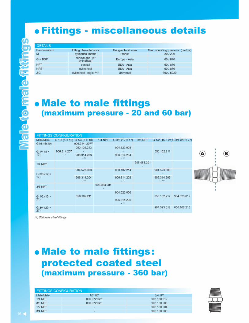
DETAILS
● Fittings - miscellaneous details
Denomination Fitting characteristics Geographical area Max. operating pressure (bar/psi)M cylindrical metric France 20 / 290
G = BSP conical gas (or cylindrical) Europe - Asia 60 / 870
NPT conical USA - Asia 60 / 870NPS cylindrical USA - Asia 60 / 870JIC cylindrical angle 74° Universal 360 / 5220
● Male to male fittings (maximum pressure - 20 and 60 bar)
FITTINGS CONFIGURATIONMale/Male G 1/8 (5 × 10) G 1/4 (8 × 13) 1/4 NPT G 3/8 (12 × 17) 3/8 NPT G 1/2 (15 × 21)G 3/4 (20 × 27)G1/8 (5x10) 906.314. 207(1)
G 1/4 (8 × 13)
906.314.207- (1)
050.102.213-
904.523.003- 050.102.211
-906.314.203- (1)
906.314.204- (1)
1/4 NPT905.083.201
-
G 3/8 (12 × 17)
904.523.003-
050.102.214-
904.523.006-
906.314.204- (1)
906.314.202- (1)
906.314.205- (1)
3/8 NPT905.083.201
-
G 1/2 (15 × 21)
050.102.211 -
904.523.006- 050.102.212
-904.523.012
-906.314.205- (1)
G 3/4 (20 × 27)
904.523.012-
050.102.215-
(1) Stainless steel fittings
A B
FITTINGS CONFIGURATION
● Male to male fittings : protected coated steel (maximum pressure - 360 bar)
Male/Male 1/2 JIC 3/4 JIC1/4 NPT 000.972.025 905.160.2123/8 NPT 000.972.028 905.160.2061/2 NPT - 905.160.2043/4 NPT - 905.160.203
Mal
e to
mal
e fi
ttin
gs
Mal
e to
mal
e fi
ttin
gs

17
● Male to male straight fittings : stainless steel
(maximum pressure : 360 bar)
FITTINGS CONFIGURATION
FITTINGS CONFIGURATION
FITTINGS CONFIGURATION
FITTINGS CONFIGURATIONMale / Male 1/2 JIC 3/4 JIC1/8 NPT 905.210.501 -1/4 NPT 905.210.502 905.210.5123/8 NPT 905.210.503 905.210.5131/2 NPT 905.210.504 905.210.5143/4 NPT - 905.210.515
● Male to male straight fittings : protective coated steel (maximum pressure : 360 bar)
Male / Male 1/2 JIC 3/4 JIC1/2 JIC 050.102.301 905.160.2013/4 JIC 905.160.201 905.160.2023/8 NPT 050.470.202 905.160.103
● Male to male elbow fittings : protective coated steel (maximum pressure : 360 bar)
1/2 JIC 3/4 JIC1/8 905.160.105 -1/4 000.972.176 905.160.102
● Male to male elbow fittings : stainless steel (maximum pressure : 360 bar)
1/2 JIC 3/4 JIC1/4 905.210.602 905.210.6123/8 905.210.603 905.210.6131/2 905.210.604 -3/4 - 905.210.615
Mal
e to
mal
e fi
ttin
gs
Mal
e to
mal
e fi
ttin
gs

18
FITTINGS CONFIGURATION
FITTINGS CONFIGURATION
FITTINGS CONFIGURATION (MAX. PRESSURE : 20 AND 60 BAR)
FITTINGS CONFIGURATION
● Male to male to male fittings (maximum pressure : 60 bar)
Description Part numberFittings 3 x G 1/2 (15 x 21) (BSP) 904.340.003
● Female to female fittings (maximum pressure : 20 - 60 bar)
Female / Female G 1/4 (BSP)G 1/4 (8 x 13) (BSP) 904.593.002G 3/8 (12 x 17) (BSP) 904.503.003M 14 x 125 050.221.401
Inlet female Outlet female Outlet female Part numberF 1/4 (8x13) F 1/4 (8x13) F 1/4 (8x13) 904.303.0021/4 NPT 1/4 NPT 1/4 NPT 905.083.301G 3/8 (12x17) (BSP) G 3/8 (12x17) (BSP) G 3/8 (12x17) (BSP) 904.303.003G 1/2 (15x21) (BSP) G 1/2 (15x21) (BSP) G 1/2 (15x21) (BSP) 904.303.004G 3/4 (20x27) (BSP) G 3/4 (20x27) (BSP) G 3/4 (20x27) (BSP) 904.303.006
● Male to female fittings (maximum pressure 20 and 60 bar)
Male\Female G 1/4 (8 × 13) G 3/8 (12 × 17) 3/8 NPS M 14 × 125 M 18 × 125 G 3/4 (20
×27) M 26 × 125
1/2 JIC050.103.537
-
G 1/4 (8 × 13)050.123.205
-904.533.003
-- - - -
1/4 NPS050.103.534
- (1)
050.123.535- (1)
050.123.526- (1)
G 3/8 (12 × 17)904.513.003
--
050.103.536- (1) - - - -
3/8 NPS - - - -050.123.532
-- -
M 14 × 125 - -050.123.523
- (1) -050.123.109
-- -
G 1/2 (15 × 21)904.513.005
-- -
050.123.605-
050.123.414-
904.533.009-
-
M 18 × 125 - -050.123.101
-- -
050.123.110 -
G 3/4 (20 × 27)904.513.011
-904.513.012
-- - - - -
M 26 × 125 - - - -050.123.106
-050.123.413
--
G 1 (26 × 34) - - - - -904.513.020
--
(1) Stainless steel fittings
Fit
tin
gs
Fit
tin
gs

19
FITTINGS CONFIGURATION
● Male to female fittings (maximum pressure : 20, 60 and 360 bar)
Male\Female 1/4 NPS M 14 × 125 M 18 × 125 1/2 JIC1/4 NPS - - 050.123.3041/2 JIC 050.123.305(1) 050.230.619 050.230.620 -M 18 × 125 - - 050.123.5213/8 NPS 050.123.5331/2 JIC elbow fitting - - 905.160.101
3/4 JIC straigth fitting - - 050.123.301(1)
(1) Stainless steel fittings
● Plugs (maximum pressure - 20 and 60 bar)
PLUGS CONFIGURATIONDescription Part numberFemale1/2 JIC 906.333.301Male1/8 NPT 906.333.108G 1/8 (5 x 10) 906.333.106G 1/4 (8 x 13) 906.333.102G 3/8 (12 x 17) 906.333.104G 1/2 (15 x 21) 906.333.103G 3/4 (20 x 27) 906.333.105
Fit
tin
gs
Fit
tin
gs
Plu
gs
Plu
gs
Straightfitting
Elbow fitting(free nut)

20
2 WAYS FEMALE/FEMALE VALVE PART NUMBERS
2 WAYS MALE/MALE VALVE PART NUMBERS
3 WAYS VALVE PART NUMBERS
QUICK FITTINGS FOR Ø 8 HOSE
QUICK FITTINGS
● ISO 6150 Quick-fit fittings (maximum pressure : 10 bar)
Type Complete assembly A and B
Part A with built-in chutter valve Part B Part C for rubber hose
Ø 7 Ø 10Ø 5 (14x125)
(1/4BSP)
(1/4BSP)
(1/4NPS)
905.030.405--
905.030.105
905.030.102--
905.030.104
905.030.406(F) 905.030.804(M) 905.030.803(F) 905.030.106(F)
905.030.203--
905.030.204--
Holdingcollar - - - 906.311.224 906.311.226
Type Part A with on/off press buttom for hose Ø 8 Part C for hose Ø 8
Ø 5 905.030.801 905.030.802
● Low pressure valves
Description Part number3 x 1/4 BSP 903.090.8043 x 1/4 BSP (stainless steel) 903.090.805
Description Input Output Part number
Ball valve
(M) G 1/4 (8 x 13) (M) M 14 x 125 050.070.205(M) G 3/8 (12 x 17) (M) M 1/4 NPS 050.070.211(M) G 1/2 (15 x 21) (M) M 18 x 125 050.070.204(M) G1/2 (15 x 21) (M) G 1/2 (15 x 21) 050.070.201(M) 3/8 (12 x 17) (M) M 18 x 125 050.070.212
Description Input Output Part numberValve (F) 1/4" BSP (8 x 13) (F) 1/4" BSP (8 x 13) 903.090.806Valve (F) 3/8" BSP (12 x 17) (F) 3/8" BSP (12 x 17) 903.090.206
A
C
B
(F)
(M)
cannelled
Qu
ick
fitt
ing
sQ
uic
k fi
ttin
gs
Val
ves
Val
ves
CA

21
PART NUMBER
VALVE PART NUMBERS
AIR BLEDDING VALVE PART NUMBER
3 WAYS VALVE PART NUMBERS
2 WAYS VALVE PART NUMBERS
● Needle valves
Description Input Output Part numberFemale/male (inlet/outlet) M 14 x 125 M 14 x 125 050.070.179
Female/male (inlet/outlet) G 1/4 (8 x 13) M 14 x 125 050.070.101
Description Part numberFemale/male/male M 14 x 125 050.070.401
● Air bleeding valves
Description Part numberInlet thread (male) G 1/4 (8 x 13) 903.093.302
● Air line output control valves
Description Input Output Part numberFemale to male (inlet/outlet) G 1/4 (8 x 13) G 1/8 (8 x 13) 050.070.190
Female/male (inlet/outlet) M 14 x 125 M 14 x 125 050.070.179
● AIRLESS fluid valves
Description Input Output Maximum fluid pressure (bar) Part number
Female to female G 3/8 (12 x 17) G 3/8 (12 x 17) 250 bar 000.750.040
BLEEDING VALVES PART NUMBERS
● Bleeding valves
Description Input Output Maximum fluid pressure (bar) Part number
Male to male (inlet/outlet) G 1/4 (8 x 13) M 18 x 125 400 000.760.000
Male to male (inlet/outlet) G 1/4 (8 x 13) M 18 x 125 240 000.760.100
Val
ves
Val
ves

24
CONFIGURATIONDescription Manometer Part numberBare pressure regulator PP (small passage) - 155.610.200Pressure regulator PP (small passage) ● 155.610.209Bare pressure regulator GP (large passage) - charged materials - 155.610.250
Pressure regulator GP (large passage) - charged materials ● 155.610.259
REGULATOR FITTINGS SMALL PASSAGEFitting Fluid Inlet F 1/4 NPS
Fluid Outlet F 1/4 BSP (x2)
REGULATOR FITTINGS LARGE PASSAGEFitting Fluid inlet (w/o adaptator) M 1/4 BSP
Fluid Outlet F 1/4 BSP (x2)
CHARACTERISTICSPressure range (bar) Inlet 40 max.
Outlet (upon version) 0,5 - 4Weight (kg) 1,3Width (cm) 8,5Height (cm) Large passages 17
Small passage 16,5Wetted parts Stainless steel, PTFE, carbide
Flu
id p
ress
ure
reg
ula
tor
- L
ow
pre
ssu
reF
luid
pre
ssu
re r
egu
lato
r -
Lo
w p
ress
ure
● Pressure regulator - manual control - low viscosity materials
Made entirely out of stainless steel, easy to flush.
● Constant Flow™
The Constant Flow®™ is a low pressure fluid regulator. It can be set-up in sin-gle or two components paint installations (water or solvent-based) between the pump or 2K machine outlets and the gun. It is aimed to prevent any pulsation.
It is made entirely of stainless steel, can be flushed easily and very useful for very low outputs and pressures.
FEATURES BENEFITSOutlet product flow is adjustable using the precision regulator
Possibility to work with very low flow
Conception with a damping product room Cancel all product variation flowContact with product part and membrane are PTFE
Optimized flushing
All stainless steel construction Compatible with most of solvent or water-based products.
Pneumatic logic Set it up into the paint cabinet

25
Description Manometer Part numberConstant Flow™ ● 1057.410.100
FITTINGSFitting Air Inlet M 1/4" NPS
Fluid Inlet M 3/8" NPSFluid Outlet M 3/8" NPS
SPECIFICATIONSMaximum temperature (°C) 60Maximum air inlet pressure (bar) 6Pressure range (bar) Command air 0.5 - 6
Outlet 1-6Weight (kg) 5Width (cm) 27Height (cm) 40Fluid viscosity 120 Cps maxWetted parts Stainless steel, aluminum PTFE
coated, PTFE diaphragm
Flu
id p
ress
ure
reg
ula
tor
- L
ow
pre
ssu
reF
luid
pre
ssu
re r
egu
lato
r -
Lo
w p
ress
ure
CONFIGURATIONDescription Material Part numberPiloted stainless steel pressure regulator Stainless steel small passages 155.610.230Piloted stainless steel pressure regulator large passage Stainless steel large passages 155.610.050Piloted non-stick treated pressure regulator Non-stick 055.370.100Piloted regulator with wall bracket and pressure gauge Stainless steel 155.610.060
MANUAL CONTROL PILOTED REGULATOR - FITTINGS AND DIMENSIONSFitting Fluid Inlet M 1/4" BSP + (M18x125, M3/8"
NPS, M3/8"BSP)Fluid Outlet F 1/4" BSP
Weight (kg) 1.6Height (cm) 20Width (cm) 8.5
LARGE PASSAGE REGULATOR - FITTINGS AND DIMENSIONSFitting Fluid Inlet M 1/4" BSP + (M18x125, M3/8"
NPS, M3/8"BSP)Fluid Outlet F 1/4 BSP
Air inlet (command) F 1/8 BSPWeight (kg) 1Height (cm) 7.3Width (cm) 8.5
SMALL PASSAGE REGULATOR - FITTINGS AND DIMENSIONSFitting Fluid Inlet F 1/4" NPS
Fluid Outlet F 1/4" BSPAir inlet (command) F 1/8" BSP
Weight (kg) 1Width (cm) 8.5Height (cm) 7.3
CHARACTERISTICSPressure range (bar) Inlet Small passage 40 max
Large passage 6 maxmanual command 10 max
Outlet 0,5 -4 barCommand air 6 max
Wetted parts Stainless steel, PTFE, carbide
● Pressure regulator - Piloted - low viscosity materials
Available in stainless steel or non-stick treated versions, excellent flushing.Manual control version available for a very fine regulation and even flow.
26
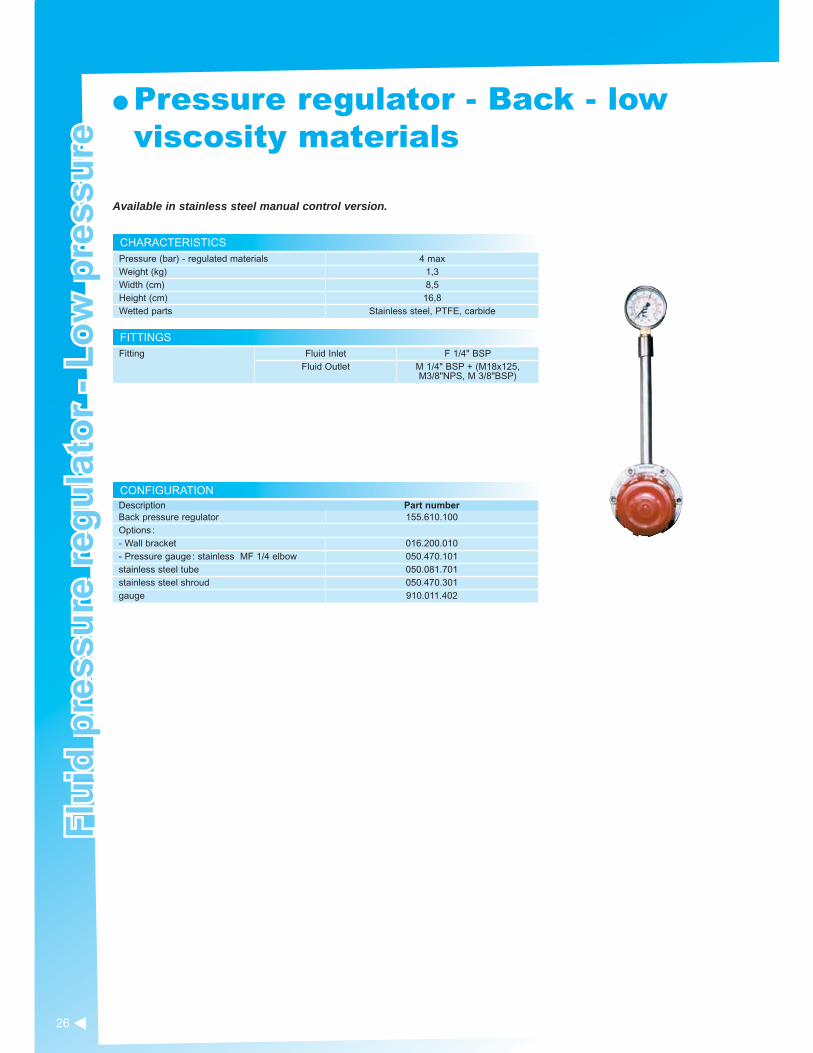
CONFIGURATIONDescription Part numberBack pressure regulator 155.610.100Options : - Wall bracket 016.200.010- Pressure gauge : stainless MF 1/4 elbow 050.470.101stainless steel tube 050.081.701stainless steel shroud 050.470.301gauge 910.011.402
FITTINGSFitting Fluid Inlet F 1/4" BSP
Fluid Outlet M 1/4" BSP + (M18x125, M3/8"NPS, M 3/8"BSP)
CHARACTERISTICSPressure (bar) - regulated materials 4 maxWeight (kg) 1,3Width (cm) 8,5Height (cm) 16,8Wetted parts Stainless steel, PTFE, carbide
Flu
id p
ress
ure
reg
ula
tor
- L
ow
pre
ssu
reF
luid
pre
ssu
re r
egu
lato
r -
Lo
w p
ress
ure
● Pressure regulator - Back - low viscosity materials
Available in stainless steel manual control version.

27
Flu
id p
ress
ure
reg
ula
tor
- M
ediu
m p
ress
ure
Flu
id p
ress
ure
reg
ula
tor
- M
ediu
m p
ress
ure
CONFIGURATIONDescription Part numberManual regulator 10 - 70 bar 155.271.730Manual regulator 10 -120 bar 155.271.735Manual regulator PH version 10 - 120 bar 155.271.770Options : Wall bracket 155.484.010
FITTINGSFitting Fluid Inlet F 3/8" NPS
Fluid Outlet F 3/8" NPS
CHARACTERISTICSPressure range (bar) Inlet 250 max
Outlet (upon version) 10 - 70 ; 10-120Weight (kg) 3,6Width (cm) 8,9Height (cm) 20Wetted parts Stainless steel, PTFE, carbide
● Pressure regulator - manual control - AIRMIX®
AIRMIX® fluid regulator is designed for low viscosity materials
FITTINGSFitting Fluid Inlet F 3/8" NPS
Fluid Outlet F 3/8" NPSAir inlet (command) F 1/4" BSP
SPECIFICATIONSPressure range (bar) Inlet (upon version) : 120 max (version 5-40) or
250 max (versions 10-70 and 10-120)Outlet (upon version) : 5-40 ; 10-70 ; 10-120
Weight (kg) (max : 10-120 version) 4,1 (max : version 10-120)Width (cm) - w/o pilot 8,9Height (cm) - (max : 10-120 version) 27,5Wetted parts Stainless steel, PTFE, carbide
● Pressure regulator - Piloted - AIRMIX®
AIRMIX® fluid regulator is designed for low viscosity materials. Piloted versionfeatures increases regulation precision and remote control
Description Part numberPiloted Airmix® regulator (with pilot) 5-40 bar 155.271.765Piloted Airmix® regulator (with pilot) 10-70 bar 155.271.750Piloted Airmix® regulator (with pilot) 10-120 bar 155.271.755Piloted Airmix® regulator (w/o pilot) 5-40 bar 155.271.760Piloted Airmix® regulator (w/o pilot) 10-70 bar 155.271.740Piloted Airmix® regulator (wi/o pilot) 10-120 bar 155.271.745
PILOTED REGULATOR WITH/WITHOUT PILOT CONFIGURATION

28
CONFIGURATIONSet-up Fitting (suction) Part numberBare - 155.271.835Equipped for wall-mounting, supplied with 2m fluid hose and fittings for pump suction
26 x 125 051.314.030
Wall bracket 155.484.010
FITTINGSFitting Fluid Inlet F 3/8" NPS
Fluid Outlet F 3/8" NPS
SPECIFICATIONSPressure range (bar) Inlet 120 max
Regulated outlet 10 - 120Weight (kg) 3,6Width (cm) 8,9Height (cm) 20Wetted parts Stainless steel, PTFE, carbide
Flu
id r
egu
lato
r -
Med
ium
pre
ssu
reF
luid
reg
ula
tor
- M
ediu
m p
ress
ure
● Pressure back regulator - AIRMIX®
ACCESSOIRESDescription Part numberWall bracket 155.484.010
CARTRIDGE PILOTED REGULATOR WITHOUT PILOT CONFIGURATIONDescription Part numberCartridge piloted regulator 5/40 155.271.719Cartridge piloted regulator 10/70 155.271.715Cartridge piloted regulator 10/160 155.271.716

29
CONFIGURATION
CHARACTERISTICS
HIGH PRESSURE GAUGES
HIGH PRESSURE GAUGES
Air
tre
atm
ent
Air
tre
atm
ent
● High pressure gauges Metal pressure gauge with glass and glycerin lens ; totally impact and solvent resistant.
Description Pressure range (bar) Fitting Internal diameter
(mm) Part number
Pressure gauge side inlet
0 - 400M 1/4 G 63
910.010.8010 - 120 910.010.802
● Diaphragm high pressure gauges The diaphragm high pressure gauge orevents any contamination by the product. Easy to flush.
Description Pressure range (bar)
Manometer fitting (Y)
Internal diameter (mm) Part number
Diaphragm high pressure gauge 0 - 250 M 3/8" NPS - F 3/8"
NPS 50 155.271.790
● Regulators 1/4" (with grey or red knob) , 1/2" and 3/4'' (with red ring) regulators are used on the compressed air lines.
Regulator 1/4" 1/2" 3/4''Max. inlet pressure (bar) 9 20 21Max. output (m3/h) 25 210 360
Description Pressure (bar) Type Part numberRed knob regulator
3,5
1/4"
016.240.000Grey knob regulator 016.380.000Grey knob regulator
5,5
016.390.000Red knob regulator 016.370.000Regulator with pressure gaugeinlet fitting 1/4 - outlet fitting M1/4" NPS
019.720.000
Grey knob regulator 9 016.360.000Red ring regulator 10 1/2'' 016.470.000Red ring regulator 10 3/4'' 016.480.000
Piloted regulator
Piloted regulator-manual control

30
CONFIGURATION RÉGULATEURS
PART NUMBERS
SPECIFICATIONSAir output (m3/h) 37Maximum fluid pressure (bar) 10Height (cm) 29Fitting Air Inlet F8 x 13GSet-up 1 regulated pressure gauge
1 valve F 1/4 G1 ball valve F 1/4 G
2 air outlet taps M 1/4 NPS
● DE 37 Purifier-regulator with filter cartridges Usually fitted in the paint cabins. Its twin-body construction ensures completely water and oil free.Technical characteristics :
● Maximum operating air output : 37 m3/h - 22 cfm● Maximum operating air pressure : 10 bar/145 psi● Height : 290 mm ● Air inlet opening : F8 x 13G
Standard equipment :
● One regulated pressure gauge● One F8 x 13 Valve● One tap valve F8 x 13● Two air outlet taps : M 14 x 125
Description Part numberPurifier with DE 37 regulator 015.240.000Blue cartridge for water 015.230.500Red cartridge for oil 015.230.200Felt cartridge seal (2 per cartridge) 015.010.006
● Regulators, filters and lubricators
Regulators with pressure gauges, filters and lubricators with polycarbon reservoirs are all modu-lar, allowing you to put together the best air treatment equipment for your needs.● Filter with trunnion deflector, transparent polycarbon reservoirs (heat resistant up to 50°C), manual bleed and a bronze filter capable of holding all particles larger than 5 microns.● Regulator with pressure gauge : self-regulating and vibration free, pressure gauges from 0 to 12 bar/180 psi, equip-ped with automatic decompression system● Lubricator with transparent polycarbon lid (heat resistant up to 50°C), flush adjustment screw ; it lubricates by fine vaporisation● Maximum operating pressure : 12 bar/180 psi
Type Inlet diameter Outlet diameter Output at 9 bar (l/mn) Part number
Regulator with gaugeM 150/2 1/4 1/4 1000 004.601.100M 250/3 1/2 1/2 5250 004.601.300Filter with polycarbonate tankM 100/2 1/4 1/4 1760 004.603.100M 200/2 3/8 3/8 7000 004.603.200Lubricator with polycarbonatre tankM 110/2 1/4 1/4 2500 004.604.100M 210/3 1/2 1/2 5250 004.604.300
Air
tre
atm
ent
Air
tre
atm
ent

31
PART NUMBERS
● AccessoriesAllow the easy assembly and fitting of regulators, lubricators and filters to provide the ideal system.
Description Part number1/8"square pressure gauge - maxi pressure 12 bar 004.601.001
Regulator support bracket F 171/1 for 1/8" and 1/4" 004.601.002
Regulator support bracket F 176/1 for 3/8" and 1/2" 004.601.201
● 3000 type filter systems
With active carbon filter
CONFIGURATION
PART NUMBER
For a clean spraying air.With active carbon The 3000 type filter system with wall mounting kit is made up of :
1 Prefilter with an air regulator, a control gauge and a purge- 5 microns filtration- holding dust and water condensats
1 coalescent filter with a purge and 2 quick air fittings outlets- filtration at 0.01 micron- holding oil and solid particles
Option : An active carbon filter - for filtering odours and oil vapours (to be mounted after the submicronic filter instead of the quick fitting)
Description Part numberType 3000 filter assembly-inlet fitting : F 1/2" G-outlet fitting : F 1/2" Gsupplied with a T fitting and 2 quick fittings Ø 5
Cartridge 5mCartridge 0.01m
151.250.500
151.250.501 151.250.502
Option : active coal filter type 3000 inlet : M 1/2" G outlet : F 1/2" G
151.250.600
Active coal cartridge 151.250.601
● Pressure gauges Built to last in metal with glass lenses, they are completely impact and solvent resistant.
Description Internal diameter (mm) Pressure range (bar) Part numberPressure gauge - side inlet
50
0 - 10 910.011.4020 - 4 910.011.404
Pressure gauge - central inlet
0 - 6 910.011.4030 - 16 910.011.405
Air
tre
atm
ent
Air
tre
atm
ent

32
CONFIGURATION
CONFIGURATION
CONFIGURATION
Acc
esso
ries
Acc
esso
ries
● Suction rods
Hoses Inter. Diameter(mm)
HosesHoses thread
TubePart numberLength (mm) Material Ext. diameter
(mm) Height (mm) Material
10
1000Nitrile
F 18 × 125 16.5/18 600
Inox
049.596.010-
19 F 26 × 125 25 600049.596.110
-
19 F 26 x 125 25 1000049.596.130
-
10 F 18 x 125 16,5/18 600049.596.210
- (1)
25 1500 F 38 x 150 25 600049.597.100
-
(1) Raccord coudé côté aspiration pompe.
● Flushing rodsHoses Inter. Diameter(mm)
HosesHoses thread
TubePart numberLength (mm) Material Ext. diameter
(mm) Height (mm) Material
10 1000 Nitrile F 18 × 125 16.5/18 600 Inox
049.596.000-
049.596.200- (1)
(1) An elbow fitting on the pump suction side
● Blow gunFor blowing-off dust from various surfaces.
Description Fitting Part numberBlow gun F 1/4'' BSP 129.371.000
STRAINERS
● StrainersSuction rod P.N.
height (mm) Ø external(mm) Material Filtration size Ø tube for
passage (mm) Strainer P.N.mm mm Micron Mesh
049.596.010-
60112
4066
polyamide
3001000
5015
16,518
051.531.600-
149.591.400-
049.596.110 -
112 66 1000 15 25149.591.400
-049.596.130
-112 66 1000 15 25
149.591.400-
049.596.210- (1)
60112
4066 1000 50
1516,518
051.531.600-
149.591.400-
049.597.100-
112 66 1000 15 25149.591.400
-
(1) An elbow fitting on the pump suction side

33
AGITATORS
● CartsDescription Part numberSingle Post Cart 051.730.110Two Post Cart w/o plate 051.221.000Two Reinforced Arms 051.231.000Two Post Pump Mounting Plate 056.100.199
● Agitators for 20 litres drums
Description Part numberBare agitator 051.332.610Agitator with 25 cm hose 051.332.600Agitator with 5 m hose 049.220.710New cover Ø325 with agitator 903.290.101System for barrel mounting 049.220.720
● Lubricants for pump fittings
VISCOSITY CUP
LUBRICANT FOR PUMP PACKINGSDescription Part numberLubricants for pump fittingsT lubricant (1/4 l) can for solvent-based paints 149.990.020
Kit of 3 T lubricant cans (2L each) 151.260.820Kit of 3 P lubricant cans (2L each) 151.260.821GreaseVaseline 1 kg "special PMP" 560.440.002Box of 450 g PTFE grease 560.440.001Techni Lub tube 560.440.101Box of graphite black grease (1kg) 560.420.005
● Viscosity cupThe viscosity is proportional to the dropping time according to the AFNOR n°4 scale (in seconds)
Description Part numberViscosity cup N° 4 CA4 049.221.400

34
PART NUMBERS
THICKNESS GAUGE FROM 1 TO 80 1000 MILSCALE
● Wet film thickness gauge
Description Part numberThickness gauge 000.790.020
● Miscellaneous
Description Part number
M22/MVX gun wrench 049.030.042
M21, J4 and J5 gun wrench 049.030.021
Wrench for AIRMIX® and AIRLESS filters 049.030.018
Adhesive-roller with Kremlin logo (75mm x 100m) 571.141.003
Large size brush 906.300.101
Small size brush 906.300.102
Wooden spatulas (pack of 5) 149.220.600
Acc
esso
ries
Acc
esso
ries

35
No
tes
No
tes

36
No
tes
No
tes

Kremlin Rexson reserves the right to modify its equipment and/or specifications without notice.Kremlin, Airmix®, Airless®, Regulex®, Flowmax® are registered trademarks.
All rights reserved. No part of this publication may be reproduced, stored in a retrieval system, or transmitted, in any form or by any means, electronic,mechanical, photocopying, recording or otherwise, without the prior permission of KREMLIN REXSON.
ATEX Directive ( Explosive Atmosphere)
ATEX 94/9/CE Directive : European (EU) regulation for the use of electrical and non-electrical equipment which may be used in explosive atmospheres, includingpumping and spraying equipment in potentially explosive atmospheres.
From 1 July 2003, it will be necessary for all products placed on the market or put into use to comply with the ATEX Directive, even if they are only intended for use in their country of origin.All user will have to be compliant with the Directive at the latest on 30 June 2006 for existing equipment (ATEX 99/92 CE).
Compliant KREMLIN equipment are in Group II, category 2G (equipment designed to ensure a high level of protection). They can be used in zone 1 and 2 without any restriction.
Nota : Group II – Category 2: equipment designed to ensure a high level of protectionG : gas and vapourZone 1 : potential hazard (spray booth, preparation area)Zone 2 : minimal hazard
Impr
essi
on
: A
CT
IS -
16-
18, q
uai
de l
a L
oire
- 7
5019
PA
RIS