nº kj-mt-1707-i-0307 couplings mt gear couplings.pdf · the mt gear coupling is a steel...
TRANSCRIPT

couplings
model MTCrowned tooth gear couplings
Nº KJ-MT-1707-I-0307

2
JAURE’s MT Series: a NewCrowned - Tooth Gear coupling
Jaure´s competence in power trans-mission systems is based on morethan 40 years of experience in thedevelopment and manufacture of cou-plings and other power transmissionelements.This is particularly testified by themost extensive supply of gear cou-plings all over the world, being one ofthe world’s leaders in the fields ofpower transmission.Computer-aided designs and the lat-est manufacturing CNC machines andtesting equipment ensure that ourproducts always reflect the state of theart of drive components.This know-how enable us to introducethe new crowned tooth gear couplingsJAURE’s MT series.
Improvements and generalfeatures
The new MT series excels thanks totechnical and production improve-ments based on our mentioned expe-rience and thus gives:
• Very large torque capacity, withoutthe sacrifice in safety factors or lifeexpectancy.• Higher permissible additionalloads, an important feature for appli-cations with large starting torque, orlarge short-circuit conditions.• Larger than usual hub bores,which allows more favourable sizeselection of the coupling for a certainshaft diameter. This also means thatyou can select a most economicalcoupling for your particular applica-tion.• DNV Type Approval certificates forour standard MT range certify that ourMT gear couplings are found to complywith DET NORSKE VERITAS´rules forclassification of ships and MobileOffshore Units, High Speed and LightCrafts. Our couplings are acceptedboth for the main propulsion and aux-iliary equipment.• A Real Complete Range, offers acomprehensive and simplified selec-tion of crowned tooth gear couplingsof widely varying range.
Gear couplings to cover all different
Inventory of standard productsand of materials. Quick Service.
In order to provide the quickest delive-ry, we maintain an ample inventory ofstandard components and of specialmaterials required for most specialorders. Our inventory includes ourbasic designs (MT, MTX, MTD, MTN,etc.) for all sizes up to 260 mm. bores.However, we also stock semi-finishedmaterial to manufacture larger sizes orspecial designs on a quick turnaround.Even couplings subjected to acceptanceby different classification societies likeLRS, GL, DNV, BV and RINA to mention
industrial applications needs. Eventhough most applications can usestandard couplings, there are numer-ous applications that are unique, andrequire special solutions. However,our final target is always to provide ourcustomers with the best technicalsolutions at optimum economy, offer-ing the:
Highest quality
The design, manufacturing and salesof all of our gear couplings and drivecomponents are integrated into ourQuality System, according to UNE-EN-ISO 9001: 94 certified by DETNORSKE VERITAS (DNV). ThisQuality Policy covers all the differentdepartments at JAURE.
®
3
2
1

Jaure´s line of MT cou-plings complies withAGMA standard relatedto flange and bolt holes.We can therefore supplycouplings for replace-ment of competitor products manufac-tured to AGMA standards. Not onlythat, our couplings are interchange-able with other manufacturer prod-ucts, but also our inventory ensuresquick delivery at competitive prices.(See the table of MT flange dimen-sions based on AGMA standards onpage 24).
Special designs
Both modified standard types andspecial designs are available in anyrequired size irrespective of quantity.Modified types essentially consists ofelements of the basic series whichhave been slightly changed orequipped with additional components.On the other hand, pure specialdesigns are normally unique designsto a certain application. Jaure´sEngineering Depar tment closely
cooperates withcustomer’s engi-neers to createthe best productfor their needs. A few examplesof our specialdesigns andcustom-madesolutions areshown on page25.
Maybe the best example of specialdesigns are the roll mill drives knownas “spindles” in the jargon (spindlegear couplings). These componentsmust be designed and manufacturedso they will be prepared to cope with:-The extremely reduced space indiameter with regard to the power tobe transmitted.-The great shaft-to-shaft span, whichcan be as much as 7 meters.- High angular misalignment ability (upto about 4°) under rated torque.- High angular misalignment ( up toabout 6°) when unloaded.- The need for safe and special seal-ing joint systems, that can retain thelubricant and prevent the entrance ofcontaminants even under very severeconditions.These special couplings are made ofhighly alloyed steels, and the teeth areboth through hardened and superfi-cially treated (either by nitriding, car-burizing or induction hardening ) andinclude special systems of floatingjoints.Jaure´s Engineering Department willbe glad to work with you to designcouplings to fit your most demandingapplications.
1. Partial workshop view.
2. Gear hobbing machine.
3. Gear shaping machine.
4. Couplings ready for expedition.
5. Inventory of standard components.
6. ISO 9001 certified firm & Type
Approvals from DNV.
7. Gear sleeve inspection.
8. View of JAURE´s facilities.
3
4
some of them, are not except from this.Our stock of components and materi-als allow us to offer the most rapiddelivery, the quickest service and supportin case of a break down or event ofcoupling damage.
Compliance with AGMA standard.Interchangeability.
7
8
6
5

®
4
Summary of Contents• Coupling description
• Coupling selection
• Coupling types:
MT
MTCL
MTX
MTD
MTS
MTV
MTF
MTFE
6
7 - 8
9
10
11
12
13
14
15
16
Basic Design
With Longer Hubs
Design with IntermediateSpacer
With Floating Shaft
Continuous Sleeve Design
Vertical Coupling
Version with IntermediateBrake Drum
Version with side BrakeDrum
Page
Type Series Version

®
5
• Coupling types (cont.):
• Equivalences with former JAURE gear couplings 24
• Flange dimensions. AGMA standard 24
• Special designs 25 - 27
• Recommendations for shaft/bore fits 28
• Critical speeds 28
• Keyway and puller hole data 29
• Installation and maintenance instructions 30 - 32
• Applications 33 - 35
MTFS
MTCO
MTB, MTBR
MTST-B
MTSR-P
MTES
MTN
17
18
19
20
21
22
23
Version with Brake Disc
Extended Sleeve Coupling
Safety Couplings (Shear Pins)
Safety Coupling (Voith Safeset® Coupling)
Safety Coupling (Voith Safeset® Coupling)
Disengaging Coupling
Full Range with covers
PageType Series Version

Technical modifications reserved6
Coupling Description
The MT gear coupling is a steel double-jointed coupling.The coupling is flexible to accomodate misalignment, buttorsionally stiff.
It is formed by two Item 1 hubs which engage a flangedsleeve with internal straight parallel teeth. Item 2-3 (4-5).As a result of the teeth curvature, if shafts misalignmentoccurs, the hubs can oscillate in the flanged sleeve. It isnearly impossible to have corner pressure on the teeth orstiffness on the coupling parts, because the coupling actsas a double joint.
High pressure grease lubrication supplied by centrifugalforce is provided for diminished teeth friction and wearing.Good sealing is achieved with toroidal gaskets.
The teeth are machined with precision gear machines ina process which guarantees uniform contact on all theteeth.
Curved face teeth couplings are flexible enough to com-pensate all types of misalignments and axial movements.
Three types of misalignment must be effectively accom-modated by a flexible coupling.
1. Parallel Offset – axes of connected shafts are parallel,but not in the same straight line.
2. Angular – axes of shafts intersect at center point ofcoupling, but not in the same straight line
3. Combined Angular Offset – axes of shafts do not inter-sect at point of coupling and are not parallel.
®
Fig. 1: Detail of the crowned tooth with angular misalignment.
Fig. 2: Coupling components.
Fig. 3: Shaft misalignment.
1) Hub2) Sleeve3) Sleeve (for o-ring)4) Sleeve (male)5) Sleeve (female)6) O-ring7) Cover8) Gasket9) Oil Plug
10) O-ring11) Bolt12) Self Locking Nut13) Lock washer14) Nut15) Bolt16) Lock washer17) O-ring
End float Offset Angular End float, offset andangular

7Technical modifications reserved
Coupling Selection
Coupling size for a certain drive depends not only on the drive unit power and speed but also on the angular misalignmentand the type of machines to be coupled.
When couplings are well aligned, every tooth transmits equally the torque.
If there is an angular shaft misalignment the tooth pressure is uneven, reducing the capacity of the coupling.
The power rating of our couplings have been calculated for an 0°30’ angle for each coupling half. The allowed capacity is±1° for each half. In special cases and according to specific demands higher-angular misalignment can be allowed.
In Fig. Nº 4 we give you a statistic curve example of the power diminishing while the misalignment of shaft increases. For1° the power capacity is reduced by 60% approximately. This rate varies according to the rotation speed.
Selection of size
1) Estimated nominal torque TN (Nm)
PN = Max. actual power in (Kw)n = Coupling speed in (r.p.m.)K = Service factor
Alternatively, multiply max. torque (Nm) by service factor and choose in both cases a listed coupling size with a higher rating, or respectively higher torque rating.
2) Should driven shafts be larger in diameter than the max. admissible bore for the chosen coupling, select the nextlarger size.
3) When using keyway system, verify pressure stresses on it in order to decide if more than one key or longer hubs arenecessary.
4) Listed speeds are max. values for unbalanced couplings. For higher operation speed, the coupling must be dynami-cally balanced. Consult our technical department in this case.
®
nTN = 9550 PN K
Angular misalignment
Torq
ue r
atin
g in
%
Fig. 4: Torque vs. misalignment.

Coupling Selection®
5) Recommended Service Factors (S.F.):In order to provide for the dynamic torque which must be transmitted, it may be necessary to increase the horsepower tobe transmitted by a factor which will allow for momentary increases in torque due to the characteristics of the equipment.The service factors shown in the table below provide a basis for estimating this allowance for specific combination of con-nected equipment.
These factors are derived from lengthy field experience with average applications and they are to be considered as a gen-eral guide. For conditions not covered by the table, good judgement must be exercised and a factor selected by referringto the type of equipment most closely related to the type of application being considered, or by detailed analysis of thedynamics of the equipment.
Example:
Find a coupling to connect a gearbox with the drum of a conveyor (not uniformly loaded)Motor power PN = 30 Kw.Drum speed n = 100 r. p. m.Gearbox shaft d1 = 80 mm.Drum - side shaft d2 = 100 mm.
Solution:
Service factor K = 1,4
As drum - side shaft d2 = 100 mm. we are forced to select coupling size MT - 100.Resulting service factor is:
Service factor
TN = 9550 30 1,4 = 4010 Nm100
K = 11700 = 2,94010
8 Technical modifications reserved
TYPE DRIVERLOAD TYPE DUTY FEATURES DRIVEN EQUIPMENT Electric motor Hidraulic Reciprocating
or Turbine motor Engine
Continuous duty without overloads Electric generatorsUNIFORM or shocks. Centrifugal pumps 1 1,25 1,5
Occasional starts-up Light fansContinuous duty with light overloads Multistage centrifugal blowersand shocks for a short time and not Reciprocating pumpsfrequently. Large fans (heavy duty)
Agitators for liquidsLIGHT Agitators for solids 1,4 1,75 2
Textile machineryMachine toolsConveyor beltsElevators
Intermittent duty with frequent light Reciprocating compressorsshocks, medium overloads for a short Cranes (travel or trolley motion)time. Hoisting equipment
MEDIUM Calenders for rubber and plastic 1,8 2 2,25Flattening machinesRolling mill drivesNon-reversing cold rolling mills
Duty with very high and frequent shocks. Bridge cranes for steel industryFrecuent reversal of the load. Mixers for rubber and plasticHigh safety degree. Cranes (heavy duty)
Pulp grindersHEAVY Marine drives 2,2 2,5 2,75
Equipment for passengers transportMine fansMill delivery and runout tablesNon-reversing cold rolling mills
Extremely high shocks and overloads Reversing cold millswith frequent and momentary reversals. Hot rolling mills
Reversing rolling mill drivesEXTRA Heavy duty in steel industry 2,5 3 3,5HEAVY Slitting machines
GrindersShear and croppers
Stone crushers

9
Coupling Types®
Technical modifications reserved
42 0.107 1.025 8.600 44 13 116 80 60 55 6 75 0,0055 5 0,04
55 0.225 2.150 6.600 58 16 152 100 79 70 6 90 0,021 10 0,06
70 0.440 4.200 5.600 75 20 178 125 101 80 6 108 0,048 17 0,17
90 0.754 7.200 4.700 95 25 213 148 124 95 8 124 0,125 28 0,24
100 1.225 11.700 4.200 105 30 240 173 143 105 8 136 0,200 40 0,36
125 1.80 17.200 3.600 130 35 279 204 170 120 8 158 0,48 65 0,50
145 2.88 27.500 3.150 150 45 318 242 205 135 10 172 0,93 95 0,70
165 3.98 38.000 2.860 165 55 346 268 216 150 10 192 1,55 134 1,30
185 5.36 51.200 2.580 190 60 389 302 250 170 10 210 2,70 185 1,75
205 7.05 67.300 2.320 210 70 425 327 275 185 12 230 4,10 240 2,2
230 9.21 88.000 2.200 230 100 457 354 300 200 12 250 5,55 273 2,8
260 14.08 134.500 2.000 260 115 527 410 340 230 12 280 9,15 412 4,5
280 18.85 180.000 1.800 280 140 540 465 370 250 16 300 14,83 525 3,0
310 26.2 250.000 1.600 310 160 585 505 410 270 16 320 22,30 750 3,6
345 33.5 320.000 1.500 345 180 650 548 450 290 16 340 36,78 890 4,8
370 41.8 400.000 1.400 370 210 690 588 490 325 20 370 52,6 1.275 5,0
390 53.4 510.000 1.300 390 230 760 640 520 345 20 400 78,8 1.390 9,0
420 69.1 660.000 1.200 420 250 805 690 560 365 20 420 110,8 1.660 9,8
460 81.7 780.000 1.100 460 275 850 730 600 400 20 450 152,4 2.010 11,5
500 104.7 1.000.000 1.050 500 300 930 780 650 410 25 490 213,8 2.460 11,5
550 125.7 1.200.000 950 550 325 995 850 710 430 25 520 309,8 3.070 14,5
590 167.5 1.600.000 900 590 350 1.055 910 760 470 25 550 422 3.410 23
620 188.5 1.800.000 850 620 375 1.140 970 810 500 30 600 677 4.550 23
650 199.0 1.900.000 800 650 400 1.190 1.020 840 520 30 630 762 5.035 30
680 219.9 2.100.000 750 680 425 1.250 1.080 890 540 30 650 850 6.270 36
730 277.3 2.600.000 700 730 450 1.300 1.150 950 570 30 680 1.210 6.910 38
800 397.9 3.800.000 660 800 475 1.420 1.270 1.050 600 30 725 1.620 9.750 46
a
D D2
d1 d2
l1 l2
S
D1
S
l1 l2a
d1D D2
D1
d2
SS
Size
(1) (2) Max.Speed PN (KW) TN Nominal n max.(3)
n(Nm) (r.p.m.) D D1 D2 l1 - l2 a S (5) (Kgm2) (Kg.) (Kg.)
(4) d1 - d2
max. min.
Size MT 42-260 Size MT 280-800
(1) PN = Nominal Power in (Kw); n = r.p.m.(2) TN = Nominal Torque in Nm; During start up the coupling can be loaded at 200% of nominal torque capacity.(3) Consult JAURE for couplings operating at higher speeds.(4) Max. admissible bore for couplings with DIN 6885/1 keys. For other types of keys or connections please consult JAURE.
In case pulling holes are used verify page 29 for maximum shaft diameter.(5) Clearence to align coupling hubs and replacement of sealing rings.(6) GD2 = 4J.(7) J and Weight are given for mínimum bore.
Type MT Basic design
DIMENSIONS (mm.) J (6) Weight Lubricant(7) (7)

10
Coupling Types®
Technical modifications reserved
42 0.107 1.025 8.600 44 13 116 80 60 110 6 130 0,066 7,1 0,04
55 0.225 2.150 6.600 58 16 152 100 79 110 6 130 0,021 12,9 0,06
70 0.440 4.200 5.600 75 20 178 125 101 140 6 170 0,057 24,0 0,17
90 0.754 7.200 4.700 95 25 213 148 124 170 8 200 0,152 41,6 0,24
100 1.225 11.700 4.200 105 30 240 173 143 170 8 200 0,242 55,6 0,36
125 1.80 17.200 3.600 130 35 279 204 170 210 8 250 0,596 95,7 0,50
145 2.88 27.500 3.150 150 45 318 242 205 250 10 290 1,242 152 0,70
165 3.98 38.000 2.860 165 55 346 268 216 250 10 290 1,884 188 1,30
185 5.36 51.200 2.580 190 60 389 302 250 310 10 350 3,54 286 1,75
205 7.05 67.300 2.320 210 70 425 327 275 310 12 350 5,20 349 2,2
230 9.21 88.000 2.200 230 100 457 354 300 350 12 400 7,40 421 2,8
260 14.08 134.500 2.000 260 115 527 410 340 440 12 490 13,4 677 4,5
280 18.85 180.000 1.800 280 140 540 465 370 440 16 490 20,2 800 3,0
310 26.2 250.000 1.600 310 160 585 505 410 440 16 490 29,5 1.048 3,6
345 33.5 320.000 1.500 345 180 650 548 450 560 16 610 53,4 1.456 4,8
370 41.8 400.000 1.400 370 210 690 588 490 560 20 610 72,8 1.843 5,0
390 53.4 510.000 1.300 390 230 760 640 520 700 20 760 99,1 1.990 9,0
420 69.1 660.000 1.200 420 250 805 690 560 700 20 760 160 2.697 9,8
460 81.7 780.000 1.100 460 275 850 730 600 860 20 940 240 3.622 11,5
500 104.7 1.000.000 1.050 500 300 930 780 650 860 25 940 332 3.304 11,5
550 125.7 1.200.000 950 550 325 995 850 710 860 25 940 470 5.182 14,5
590 167.5 1.600.000 900 590 350 1.055 910 760 860 25 940 614 5.598 23
620 188.5 1.800.000 850 620 375 1.140 970 810 1.000 30 1.100 994 7.728 23
650 199.0 1.900.000 800 650 400 1.190 1.020 840 1.000 30 1.100 1.110 8.263 30
680 219.9 2.100.000 750 680 425 1.250 1.080 890 1.000 30 1.100 1.272 9.738 36
730 277.3 2.600.000 700 730 450 1.300 1.150 950 1.000 30 1.100 1.723 10.620 38
800 397.9 3.800.000 660 800 475 1.420 1.270 1.050 1.000 30 1.100 2.338 14.074 46
a
D D2
d1 d2
l1 l2
S
D1
D1
l1 l2a
d1D D2
d2
S
Size
(1) (2) Speed (3)PN (KW) TN Nominal n max.
n(Nm) (r.p.m.) D D1 D2 l1 - l2 a S (5) (Kgm2) (Kg.) (Kg.)d1 - d2 (4)
max. min.
Size MTCL 42-260 Size MTCL 280-800
Type MTCL Longer hubs
DIMENSIONS (mm.) J (6) Weight Lubricant(7) (7)
(1) PN = Nominal Power in (Kw); n = r.p.m.(2) TN = Nominal Torque in Nm; During start up the coupling can be loaded at 200% of nominal torque capacity.(3) Consult JAURE for couplings operating at higher speeds.(4) Max. admissible bore for couplings with DIN 6885/1 keys. For other types of keys or connections please consult JAURE.
In case pulling holes are used verify page 29 for maximum shaft diameter.(5) Clearence to align coupling hubs and replacement of sealing rings.(6) GD2 = 4J.(7) J and weight are given for minimum bore.

11
Coupling Types®
Technical modifications reserved
42 0.107 1.025 44 13 116 80 60 55 75 0,0055 5 0,04
55 0.225 2.150 58 16 152 100 79 70 90 0,021 10 0,06
70 0.440 4.200 75 20 178 125 101 80 108 0,048 17 0,17
90 0.754 7.200 95 25 213 148 124 95 124 0,125 28 0,24
100 1.225 11.700 105 30 240 173 143 105 136 0,200 40 0,36
125 1.80 17.200 130 35 279 204 170 120 158 0,48 65 0,50
145 2.88 27.500 150 45 318 242 205 135 172 0,93 95 0,70
165 3.98 38.000 165 55 346 268 216 150 192 1,55 134 1,30
185 5.36 51.200 190 60 389 302 250 170 210 2,70 185 1,75
205 7.05 67.300 210 70 425 327 275 185 230 4,10 240 2,2
230 9.21 88.000 230 100 457 354 300 200 250 5,55 273 2,8
260 14.08 134.500 260 115 527 410 340 230 280 9,15 412 4,5
280 18.85 180.000 280 140 540 465 370 250 300 14,83 525 3,0
310 26.2 250.000 310 160 585 505 410 270 320 22,30 750 3,6
345 33.5 320.000 345 180 650 548 450 290 340 36,78 890 4,8
370 41.8 400.000 370 210 690 588 490 325 370 52,6 1.275 5,0
390 53.4 510.000 390 230 760 640 520 345 400 78,8 1.390 9,0
420 69.1 660.000 420 250 805 690 560 365 420 110,8 1.660 9,8
460 81.7 780.000 460 275 850 730 600 400 450 152,4 2.010 11,5
500 104.7 1.000.000 500 300 930 780 650 410 490 213,8 2.460 11,5
550 125.7 1.200.000 550 325 995 850 710 430 520 309,8 3.070 14,5
590 167.5 1.600.000 590 350 1.055 910 760 470 550 422 3.410 23
620 188.5 1.800.000 620 375 1.140 970 810 500 600 677 4.550 23
650 199.0 1.900.000 650 400 1.190 1.020 840 520 630 762 5.035 30
680 219.9 2.100.000 680 425 1.250 1.080 890 540 650 850 6.270 36
730 277.3 2.600.000 730 450 1.300 1.150 950 570 680 1.210 6.910 38
800 397.9 3.800.000 800 475 1.420 1.270 1.050 600 725 1.620 9.750 46
l1
d1D2D
d2
S S
l2(Distance Between Shafts Ends)
DBSE (8)
D1
Size
(1) (2) Max.Speed PN (KW) TN Nominal n max.
n(Nm) r.p.m.(3) D D1 D2 l1 - l2 S (5) (Kgm2) (Kg.) (Kg.)
d1 - d2 (4) max. min.
Size MTX 42-260 Size MTX 280-800
(1) PN = Nominal Power in (Kw); n = r.p.m.(2) TN = Nominal Torque in Nm; During start up the coupling can be loaded at 200% of nominal torque capacity.(3) See page 28 for critical speed of spacer.(4) Max. admissible bore for couplings with DIN 6885/1 keys. For other types of keys or connections please consult JAURE.
In case pulling holes are used verify page 29 for maximum shaft diameter.(5) Clearence to align coupling hubs and replacement of sealing rings.(6) GD2 = 4J. Without spacer.(7) J and weight are given for minimum bore and without spacer.(8) Distance to be specified by the customer. DBSE is distance between shafts ends, not between flanges.
Type MTX with spacer
DIMENSIONS (mm.) J (6) Weight Lubricant(7) (7)
Th
e m
ax. r
.p.m
. sp
eed
is li
mit
ed b
y w
eig
ht
and
crit
ical
sp
eed
of
spac
er.

12
Coupling Types®
Technical modifications reserved
42 0.107 1.025 44 13 55 116 80 60 80 55 7 0,01195 11 0,04
55 0.225 2.150 58 16 70 152 100 79 100 70 7 0,0443 22 0,06
70 0.440 4.200 75 20 90 178 125 101 125 80 7 0,100 36 0,17
90 0.754 7.200 95 25 105 213 148 124 148 95 8 0,248 60 0,24
100 1.225 11.700 105 30 120 240 173 143 173 105 8 0,426 100 0,36
125 1.80 17.200 130 35 145 279 204 170 204 120 8 1,000 138 0,50
145 2.88 27.500 150 45 170 318 242 205 242 135 10 1,94 205 0,70
165 3.98 38.000 165 55 190 346 268 216 268 150 10 3,14 280 1,30
185 5.36 51.200 190 60 215 389 302 250 302 170 10 5,70 400 1,75
205 7.05 67.300 210 70 230 425 327 275 327 185 11 8,56 510 2,2
230 9.21 88.000 230 100 250 457 354 300 354 200 11 11,45 590 2,8
260 14.08 134.500 260 115 290 527 410 340 410 230 12 21,23 890 4,5
280 18.85 180.000 280 140 290 540 465 370 410 250 14 28,53 1.045 3,0
310 26.2 250.000 310 160 350 585 505 410 460 270 14 43,94 1.430 3,6
345 33.5 320.000 345 180 380 650 548 450 500 290 16 71,20 1.770 4,8
370 41.8 400.000 370 210 410 690 588 490 540 325 18 103,40 2.390 5,0
390 53.4 510.000 390 230 450 760 640 520 590 345 18 140 2.590 9,0
420 69.1 660.000 420 250 480 805 690 560 630 365 18 216 3.344 9,8
460 81.7 780.000 460 275 520 850 730 600 680 400 18 300 4.075 11,5
500 104.7 1.000.000 500 300 560 930 780 650 730 410 22 420 4.930 11,5
550 125.7 1.200.000 550 325 600 995 850 710 790 430 22 608 6.120 14,5
590 167.5 1.600.000 590 350 650 1.055 910 760 850 470 22 850 7.190 23
620 188.5 1.800.000 620 375 680 1.140 970 810 890 500 25 1.140 9.014 23
650 199.0 1.900.000 650 400 710 1.190 1.020 840 930 520 25 1.470 10.135 30
680 219.9 2.100.000 680 425 770 1.250 1.080 890 1.010 540 25 1.820 12.400 36
730 277.3 2.600.000 730 450 810 1.300 1.150 950 1.060 570 25 2.430 13.960 38
800 397.9 3.800.000 800 475 900 1.420 1.270 1.050 1.170 600 25 3.500 18.800 46
l1 l l l2
(Distance Between Shafts Ends)DBSE (3)
a a
d1D
d
d2 D3D
2 D1
Size
(1) (2) Max Speed PN (KW) TN Nominal n max.
n(Nm) D D1 D2 D3 l1 - l2 a (Kgm2) (Kg.) (Kg.)d (4) (4) d1-d2
max. min. max.
Size MTD 42-260
Size MTD 280-800
Type MTD with floating shaft
DIMENSIONS (mm.) J (5) Weight Lubricant(6) (6)
(1) PN = Nominal Power in (Kw); n = r.p.m.(2) TN = Nominal Torque in Nm; During start up the coupling can be loaded at 200% of nominal torque capacity.(3) Distance to be specified by the customer. DBSE is distance between shafts ends, not between flanges.(4) Max. admissible bore for couplings with DIN 6885/1 keys. For other types of keys or connections please consult JAURE.
In case pulling holes are used verify page 29 for maximum shaft diameter.(5) GD2 = 4J. Without intermediate shaft.(6) J and weight are given for minimum bore and without shaft. The coupling is supplied with a sealing compound on the intermediate shaft keyways.
Th
e m
ax. r
.p.m
. sp
eed
is li
mit
ed b
y w
eig
ht
and
crit
ical
sp
eed
of
flo
atin
g s
haf
t.P
leas
e co
nsu
lt J
AU
RE
.

13
Coupling Types®
Technical modifications reserved
l 2a
d2
B
S
D D1
d1
l 1 l1 l2a
d2
B
S
D D1
d1
Size MTS 22-260 Size MTS 280-800
Type MTS with continuous sleeve
(1) PN = Nominal Power in (Kw); n = r.p.m.(2) TN = Nominal Torque in Nm; During start up the coupling can be loaded at 200% of nominal torque capacity.(3) Consult JAURE for couplings operating at higher speeds.(4) Max. admissible bore for couplings with DIN 6885/1 keys. For other types of keys or connections please consult JAURE.
In case pulling holes are used verify page 29 for maximum shaft diameter.(5) Clearence to align coupling hubs and replacement of sealing rings.(6) GD2 = 4J.(7) J and weight are given for minimum bore.
22 0,053 500 12.000 22 8 56 36 30 4 57 47 0,0005 0,81 0,004
32 0,068 650 10.500 32 10 70 48 40 4 71 56 0,0010 1,72 0,008
38 0,079 750 9.500 38 14 80 56 45 4 84 68 0,0020 2,52 0,010
50 0,120 1.150 9.000 50 18 96 68 55 6 91 74 0,0037 3,75 0,022
55 0,225 2.150 7.000 58 20 112 80 70 6 108 85 0,0086 7,12 0,034
70 0,440 4.200 5.600 75 20 140 101 80 6 130 106 0,0342 15,26 0,050
90 0,754 7.200 4.700 95 25 164 124 95 8 145 116 0,0753 24,8 0,070
100 1,225 11.700 4.200 105 30 185 143 105 8 150 120 0,129 34 0,085
125 1,80 17.200 3.600 130 35 215 170 120 8 165 130 0,268 52,6 0,115
145 2,88 27.500 3.150 150 45 255 205 135 10 195 150 0,631 86 0,16
165 3,98 38.000 2.860 165 55 280 216 150 10 215 170 0,952 108 0,30
185 5,36 51.200 2.580 190 60 317 250 170 10 245 190 1,830 162 0,40
205 7,05 67.300 2.320 210 70 345 275 185 12 275 210 2,865 211 0,50
230 9,21 88.000 2.200 230 100 374 300 200 12 295 226 4,225 256 0,60
260 14,08 134.500 2.000 260 115 414 340 230 12 355 266 7,50 366 1,25
280 18,85 180.000 1.800 280 140 465 370 250 16 345 275 11,12 446 3,50
310 26,2 250.000 1.600 310 160 505 410 270 16 375 295 16,21 558 3,90
345 33,5 320.000 1.500 345 180 548 450 290 16 400 315 25,00 712 4,80
370 41,8 400.000 1.400 370 210 588 490 325 20 450 350 37,50 906 6,00
390 53,4 510.000 1.300 390 230 640 520 345 20 480 370 53,25 1.100 8,80
420 69,1 660.000 1.200 420 250 690 560 365 20 510 390 77,5 1.360 9,50
460 81,7 780.000 1.100 460 275 730 600 400 20 560 430 114 1.715 11,0
500 104,7 1.000.000 1.050 500 300 780 650 410 25 570 440 146 1.958 12,5
550 125,7 1.200.000 950 550 325 850 710 430 25 600 460 218 2.464 17
590 167,5 1.600.000 900 590 350 910 760 470 25 660 500 308 3.050 22
620 188,5 1.800.000 850 620 375 970 810 500 30 700 530 430 3.720 24
650 199,0 1.900.000 800 650 400 1.020 840 520 30 730 550 532 4.160 30
680 219,9 2.100.000 750 680 425 1.080 890 540 30 755 574 668 4.720 38
730 277,3 2.600.000 700 730 450 1.150 950 570 30 800 604 922 5.730 42
800 397,9 3.800.000 660 800 475 1.270 1.050 600 30 850 634 1.455 7.520 50
Size
(1) (2) SpeedPN (KW) TN Nominal n máx. (3)
n(Nm) (r.p.m.) D D1 l1 - l2 a S (5) B (Kgm2) (Kg.) (Kg.)
d1 - d2 (4) max. min.
DIMENSIONS (mm.) J (6) Weight Lubricant(7) (7)

14
Coupling Types®
Technical modifications reserved
42 0.107 1.025 8.600 44 13 116 80 60 55 8 75 3 0,006 5
55 0.225 2.150 6.600 58 16 152 100 79 70 8 90 3 0,021 10
70 0.440 4.200 5.600 75 20 178 125 101 80 8 108 3 0,048 17
90 0.754 7.200 4.700 95 25 213 148 124 95 9 124 3 0,125 29
100 1.225 11.700 4.200 105 30 240 173 143 105 9 136 3 0,20 44
125 1.80 17.200 3.600 130 35 279 204 170 120 12 158 5 0,48 68
145 2.88 27.500 3.150 150 45 318 242 205 135 13 172 5 0,90 100
165 3.98 38.000 2.860 165 55 346 268 216 150 13 192 5 1,45 134
185 5.36 51.200 2.580 190 60 389 302 250 170 14 210 5 2,70 190
205 7.05 67.300 2.320 210 70 425 327 275 185 16 230 6 4,15 255
230 9.21 88.000 2.200 230 100 457 354 300 200 16 250 6 5,60 285
260 14.08 134.500 2.000 260 115 527 410 340 230 16 280 6 9,35 420
SS
D
D2
d1
d2
D1
l2l1
a
F
Size
(1) (2) Speed (3)PN (KW) TN Nominal n max.
n (Nm) (r.p.m.) D D1 D2 l1 - l2 a S (5) F (Kgm2) (Kg.)d1 - d2 (4)
max. min.
Type MTV for vertical installation
DIMENSIONS (mm.) J (6) Weight (7) (7)
(1) PN = Nominal Power in (Kw); n = r.p.m.(2) TN = Nominal Torque in Nm; During start up the coupling can be loaded at 200% of nominal torque capacity.(3) Consult JAURE for couplings operating at higher speeds.(4) Max. admissible bore for couplings with DIN 6885/1 keys. For other types of keys or connections please consult JAURE.
In case pulling holes are used verify page 29 for maximum shaft diameter.(5) Clearence to align coupling hubs and replacement of sealing rings.(6) GD2 = 4J.(7) J and weight are given for minimum bore.For lubricant quantity and method for MTV, please consult JAURE.

15
Coupling Types®
Technical modifications reserved
D2
l 1 a
S
l2
DD1
S
B
DF
d2d1
Size
(1) (2) Speed PN (KW) TN Nominal n max.(3)
n(Nm) (r.p.m.) D D1 D2 l2 - l1 a S (5) DF B (Kgm2) (Kg.) (Kg.)
d1 - d2 (4) max. min.
(1) PN = Nominal Power in (Kw); n = r.p.m.(2) TN = Nominal Torque in Nm; During start up the coupling can be loaded at 200% of nominal torque capacity.(3) Consult JAURE for couplings operating at higher speeds.(4) Max. admissible bore for couplings with DIN 6885/1 keys. For other types of keys or connections please consult JAURE.
In case pulling holes are used verify page 29 for maximum shaft diameter.(5) Clearence to align coupling hubs and replacement of sealing rings.(6) GD2 = 4J.(7) J and weight are given for minimum bore.
Type MTF with intermediate brake drum
DIMENSIONS (mm.) J (6) Weight Lubricant(7) (7)
42 0.107 1.025 2.850 44 13 116 80 60 55 16 75 200 75 0,045 10 0,04
2.850 16 200 75 0,054 14
55 0.225 2.150 2.300 58 16 152 100 79 70 16 90 250 95 0,110 18 0,06
1.800 18 315 118 0,340 24
2.300 16 250 95 0,120 24
1.800 18 315 118 0,360 3170 0.440 4.200 75 20 178 125 101 80 108 0,17
1.650 18 350 130 0,500 35
1.450 22 400 150 0,96 42
1.800 20 315 118 0,41 42
90 0.754 7.200 1.650 95 25 213 148 124 95 22 124 350 130 0,56 46 0,24
1.450 22 400 150 1,00 56
1.800 20 315 118 0,45 54
1.650 22 350 130 0,60 59100 1.225 11.700 105 30 240 173 143 105 136 0,36
1.450 22 400 150 1,10 69
1.300 22 450 170 1,55 74
1.450 22 400 150 1,40 93
125 1.80 17.200 1.300 130 35 279 204 170 120 22 158 450 170 2,00 98 0,50
1.150 22 500 190 2,95 113
1.150 25 500 190 3,40 143
145 2.88 27.500 1.100 150 45 318 242 205 135 25 172 530 195 4,15 153 0,70
1.000 28 630 236 8,45 193
1.150 25 500 190 3,9 182
1.100 25 530 195 4,6 192165 3.98 38.000 165 55 346 268 216 150 192 1,30
1.000 28 630 236 9,0 232
800 28 710 265 15,8 277

16
Coupling Types®
Technical modifications reserved
D2
l 1 a l 2
DF d1
d2
DD1
B
S
Size
(1) (2) Speed PN (KW) TN Nominal n max.(3)
n(Nm) (r.p.m.) D D1 D2 l1 l2 a S (5) DF B (Kgm2) (Kg.) (Kg.)
d1 - d2 (4) max. min.
(1) PN = Nominal Power in (Kw); n = r.p.m.(2) TN = Nominal Torque in Nm; During start up the coupling can be loaded at 200% of nominal torque capacity.(3) Consult JAURE for couplings operating at higher speeds.(4) Max. admissible bore for couplings with DIN 6885/1 keys. For other types of keys or connections please consult JAURE.
In case pulling holes are used verify page 29 for maximum shaft diameter.(5) Clearence to align coupling hubs and replacement of sealing rings.(6) GD2 = 4J.(7) J and weight are given for minimum bore.
Type MTFE with side brake drum
DIMENSIONS (mm.) J (6) Weight Lubricant(7) (7)
42 0.107 1.025 2.850 44 13 116 80 60 95 55 6 75 200 75 0,046 12 0,04
2.850 115 200 75 0,055 17
55 0.225 2.150 2.300 58 16 152 100 79 125 70 6 90 250 95 0,113 22 0,06
1.800 140 315 118 0,353 35
2.300 130 250 95 0,140 28
1.800 145 315 118 0,380 4270 0.440 4.200 75 20 178 125 101 80 6 108 0,17
1.650 145 350 130 0,530 46
1.450 160 400 150 1,00 57
1.800 155 315 118 0,44 53
90 0.754 7.200 1.650 95 25 213 148 124 155 95 8 124 350 130 0,60 57 0,24
1.450 170 400 150 1,07 71
1.800 155 315 118 0,51 65
1.650 155 350 130 0,66 69100 1.225 11.700 105 30 240 173 143 105 8 136 0,36
1.450 170 400 150 1,13 84
1.300 180 450 170 1,60 94
1.450 200 400 150 1,45 108
125 1.80 17.200 1.300 130 35 279 204 170 210 120 8 158 450 170 2,03 119 0,50
1.150 220 500 190 3,00 129
1.150 220 500 190 3,50 159
145 2.88 27.500 1.100 150 45 318 242 205 220 135 10 172 530 195 4,35 171 0,70
1.000 250 630 236 8,75 221
1.150 235 500 190 4,3 198
1.100 235 530 195 5,1 211165 3.98 38.000 165 55 346 268 216 150 10 192 1,30
1.000 265 630 236 9,5 260
800 280 710 265 16,5 312

17
Coupling Types®
Technical modifications reserved
Optional:Self Ventilated disc
30
X
30
Bolt pos. Aquality 8.8
d1
D4
D2
D1D d2
D5
D3
l 1 l 2l 3
(1) Consult JAURE for couplings operating at higher speeds.(2) Max. admissible bore for couplings with DIN 6885/1 keys. For other types of keys or connections please consult JAURE.
In case pulling holes are used verify page 29 for maximum shaft diameter.(3) GD2 = 4J. (Values with solid disc.)(4) J and weight are given for minimum bore and with solid brake disc.
Type MTFS with brake disc
Size
Speed TN Nominal n max.(1)
(Nm) (r.p.m. ) D D1 D2 D3 D4 D5 l1 l2 l3 X Z-M Nm (Kgm2) (Kg.) (Kg.)d1(2) d2 (2) max. max.
3.000 50 315 124 105 85 82 107 117 102 9-M10 49 0,23 32
2.700 60 355 145 125 105 100 107 117 102 9-M12 86 0,37 3855 2.150 58 152 70 0,06
2.400 70 395 165 140 115 110 107 117 102 9-M14 135 0,54 46
2.100 70 445 175 146 120 112 140 117 135 12-M16 210 0,82 51
2.400 70 395 165 140 115 110 107 117 102 9-M14 135 0,56 53
2.100 70 445 175 146 120 112 140 130 135 12-M16 210 0,87 5770 4.200 75 178 80 0,17
1.900 100 495 218 190 160 155 140 145 135 12-M18 290 1,42 81
1.800 100 550 218 190 160 155 140 145 135 12-M18 290 1,88 88
2.100 70 445 175 146 120 112 140 145 135 12-M16 210 0,95 71
1.900 100 495 218 190 160 155 140 164 135 12-M18 290 1,47 9490 7.200 95 213 95 0,24
1.800 100 550 218 190 160 155 140 164 135 12-M18 290 1,92 103
1.500 105 625 238 205 170 168 140 164 135 12-M20 410 3,33 130
1.900 100 495 218 190 160 155 140 180 135 12-M18 290 1,57 109
1.800 100 550 218 190 160 155 140 180 135 12-M18 290 1,97 117100 11.700 105 240 105 0,36
1.500 105 625 238 205 170 168 140 180 135 12-M20 410 3,43 140
1.300 120 705 268 230 195 190 140 180 135 12-M22 550 5,73 171
1.500 105 625 238 205 170 168 140 196 135 12-M20 410 3,73 166
125 17.200 1.300 120 130 705 268 230 195 190 279 140 120 196 135 12-M22 550 5,93 194 0,50
1.200 135 795 300 260 220 216 140 196 135 12-M24 710 9,42 241
1.500 105 625 238 205 170 168 140 223 135 12-M20 410 4,13 200
145 27.500 1.300 120 150 705 268 230 195 190 318 140 135 223 135 12-M221 550 6,23 236 0,70
1.200 135 795 300 260 220 216 140 223 135 12-M24 710 9,82 275
1.300 120 705 268 230 195 190 140 238 135 12-M22 550 6,88 271165 38.000 165 346 150 1,30
1.200 135 795 300 260 220 216 140 238 135 12-M24 710 10,32 315
DIMENSIONS (mm.) Bolt Data J (3) Weight(3) Lubricantpos. A (4) (4)

18
Coupling Types®
Technical modifications reserved
42 0.107 1.025 8.600 44 13 116 80 60 55 6 16 26 0,0055 5 0,04
55 0.225 2.150 6.600 58 16 152 100 79 70 6 21 36 0,021 10 0,06
70 0.440 4.200 5.600 75 20 178 125 101 80 6 26 46 0,048 17 0,17
90 0.754 7.200 4.700 95 25 213 148 124 95 8 33 58 0,125 28 0,24
100 1.225 11.700 4.200 105 30 240 173 143 105 8 48 88 0,200 40 0,36
125 1.80 17.200 3.600 130 35 279 204 170 120 8 50 92 0,48 65 0,50
145 2.88 27.500 3.150 150 45 318 242 205 135 10 56 102 0,93 95 0,70
165 3.98 38.000 2.860 165 55 346 268 216 150 10 66 122 1,55 134 1,30
185 5.36 51.200 2.580 190 60 389 302 250 170 10 78 146 2,70 185 1,75
205 7.05 67.300 2.320 210 70 425 327 275 185 12 90 168 4,10 240 2,20
230 9.21 88.000 2.200 230 100 457 354 300 200 12 96 180 5,55 273 2,80
260 14.08 134.500 2.000 260 115 527 410 340 230 12 112 212 9,15 412 4,50
l1 l2a1
a
d1D2
d2 D1D
l1 l2a2
a
d1D2
d2 D1D
Size
(1) (2) Speed (3)PN (KW) TN Nominal n max.
n (Nm) (r.p.m.) D D1 D2 l1 - l2 a a1 a2 (Kgm2) (Kg.) (Kg.)d1 - d2 (4)
max. min.
Type MTCO with extended sleeve
DIMENSIONS (mm.) J (5) Weight Lubricant(6) (6)
(1) PN = Nominal Power in (Kw); n = r.p.m.(2) TN = Nominal Torque in Nm; During start up the coupling can be loaded at 200% of nominal torque capacity.(3) Consult JAURE for couplings operating at higher speeds.(4) Max. admissible bore for couplings with DIN 6885/1 keys. For other types of keys or connections please consult JAURE.
In case pulling holes are used verify page 29 for maximum shaft diameter.(5) GD2 = 4J.(6) J and weight are given for minimum bore.

19
Coupling Types®
Technical modifications reserved
L
l1 l2a
D2
D1D
D.B
.C.
D3
d1 d2 d1D2
D1D
d2 D3
D4
S
l1 DBSE l2
Shear pin types MTB / MTBR
55 0.225 2.150 4.400 58 16 152 100 79 220 70 182 42 185 0,082 20 0,06
70 0.440 4.200 4.000 75 20 178 125 101 250 80 202 42 215 0,15 30 0,17
90 0.754 7.200 3.500 95 25 213 148 124 285 95 232 42 250 0,30 45 0,24
100 1.225 11.700 3.000 105 30 240 173 143 335 105 275 65 285 0,79 82 0,36
125 1.80 17.200 2.600 130 35 279 204 170 370 120 305 65 320 1,36 116 0,50
145 2.88 27.500 2.400 150 45 318 242 205 410 135 337 67 360 2,26 158 0,70
165 3.98 38.000 2.200 165 55 346 268 216 435 150 367 67 385 3,24 205 1,30
185 5.36 51.200 1.800 190 60 389 302 250 520 170 424 84 450 6,76 305 1,75
205 7.05 67.300 1.700 210 70 425 327 275 560 185 456 86 490 9,56 380 2,2
230 9.21 88.000 1.600 230 100 457 354 300 590 200 486 86 520 12,28 428 2,8
260 14.08 134.500 1.500 260 115 527 410 340 660 230 546 86 590 19,68 605 4,5
SizeMTB
(1) (2) Speed (3)PN (KW) TN Nominal n max.
n(Nm) (r.p.m.) D D1 D2 D3 l1 - l2 L a D.B.C. (Kgm2 ) (Kg.) (Kg.)d1 - d2 (4)
max. min.
DIMENSIONS (mm.) J (6) Weight Lubricant (7) (7)
42 0.136 1.300 6490 48 13 55 145 113 65 80 153 55 123±1 80 0,035 13,8 0,07
55 0.262 2.500 5770 60 16 65 164 126 80 95 172 70 134±1 90 0,055 19,5 0,10
70 0.450 4.300 5140 70 20 80 184 147 95 112 193 80 145±2 100 0,10 30 0,12
90 0.733 7.000 4310 85 25 95 220 176 112 135 230 95 156±2 130 0,23 53 0,22
100 1.215 11.600 3810 100 30 110 240 200 135 160 260 105 186±2 140 0,42 68 0,30
125 1.990 19.000 3420 120 35 130 270 230 160 185 290 120 195±2 150 0,70 96 0,40
145 2.827 27.000 3000 140 45 145 310 256 185 210 330 135 210±2 160 1,45 137 0,60
165 4.084 39.000 2750 160 55 160 340 292 210 230 360 150 242±3 190 2,25 192 1,00
185 5.654 54.000 2450 180 60 180 380 315 230 255 405 170 265±3 210 3,75 264 1,10
205 7.225 69.000 2300 200 70 205 405 340 255 290 432 185 300±3 230 5,70 333 1,60
230 10.262 98.000 2020 220 100 225 445 377 290 320 490 200 320±3 250 9,75 460 2,00
260 13.612 130.000 1870 250 115 250 490 415 320 360 530 230 354±3 280 15,00 598 1,30
SizeMTBR
(1) (2) Speed (3)PN (KW) TN Nominal n max.
n(Nm) (r.p.m.) D D1 D2 D3 D4 l1 - l2 DBSE S (5) (Kgm2) (Kg.) (Kg.)d1 (4)
max. min.d2 (4)max.
DIMENSIONS (mm.) J (6) Weight Lubricant (7) (7)
(1) PN = Nominal Power in (Kw); n = r.p.m.(2) TN = Nominal Torque in Nm; During start up the coupling can be loaded at 200% of nominal torque capacity.(3) Consult JAURE for couplings operating at higher speeds.(4) Max. admissible bore for couplings with DIN 6885/1 keys. For other types of keys or connections please consult JAURE.(5) Clearence to align coupling hubs and replacement of sealing rings.(6) GD2 = 4J.(7) J and Weight are given for minimun bore.
TYPE MTBTYPE MTBR

20
Coupling Types®
Technical modifications reserved
70/60 1.800-3.600 60 137 75 20 178 125 101 136 80 15 108 40 M6 13 0,060 21,9 0,17
90/70 3.000-6.000 70 150 95 25 213 148 124 148 95 18 124 50 M6 13 0,145 34,6 0,24
100/80 3.900-7.800 80 166 105 30 240 173 143 157 105 18 136 50 M6 13 0,225 47,6 0,36
125/90 5.000-10.000 90 184 130 35 279 204 170 168 120 22 158 65 M8 18 0,517 74,2 0,50
145/100 7.500-15.000 100 206 150 45 318 242 205 183 135 25 172 70 M8 18 0,995 109 0,70
145/110 10.000-20.000 110 208 150 45 318 242 205 201 135 25 172 80 M8 18 1,025 11 0,70
165/120 13.000-25.000 120 237 165 55 346 268 216 209 150 26 192 90 M8 18 1,670 153 1,30
185/130 17.000-33.000 130 250 190 60 389 302 250 218 170 26 210 100 M8 18 2,84 206 1,75
185/140 20.000-40.000 140 261 190 60 389 302 250 228 170 26 210 105 M10 23 2,89 209 1,75
205/150 23.000-46.000 150 275 210 70 425 327 275 238 185 28 230 115 M10 23 4,33 267 2,20
230/160 36.000-71.000 160 300 230 100 457 354 300 253 200 28 250 120 M10 23 5,87 305 2,80
230/170 39.000-78.000 170 300 230 100 457 354 300 258 200 30 250 130 M10 23 5,92 307 2,80
260/180 49.000-98.000 180 300 260 115 527 410 340 273 230 30 280 135 M10 23 9,61 450 4,50
260/190 63.000-126.000 190 350 260 115 540 465 340 286 230 30 280 145 M10 23 9,81 462 3,00
280/200 70.000-140.000 200 350 280 140 585 505 370 296 250 34 300 150 M10 23 15,58 578 3,00
310/220 85.000-170.000 220 350 310 160 650 548 410 320 270 34 320 175 M10 23 23,23 807 3,60
1,6
D2
D1
S
d4 d2 D
l2l3 a
d3D3
d3h6
b
M (4x)
Size
TTorque Range
(Nm) d3 I3 D D1 D2 D3 I2 a S (2) d4 M b (Kgm2) (Kg.) (Kg.)d2 (1)max. min.
Type MTST-B with Safeset® safety element
DIMENSIONS (mm.) J (3) Weight Lubricant(4) (4)
(1) Max. admissible bore for couplings with DIN 6885/1 keys. For other types of keys or connections please consult JAURE.In case pulling holes are used verify page 29 for maximum shaft diameter.
(2) Clearence to align coupling hubs and replacement of sealing rings.(3) GD2 = 4J.(4) J and Weight are given for minimum bore.
Safeset® is a trade mark from Voith.
Size MTST-B 70/60-260/190
Size MTST-B 280/200-310/220
21
Coupling Types®
Technical modifications reserved
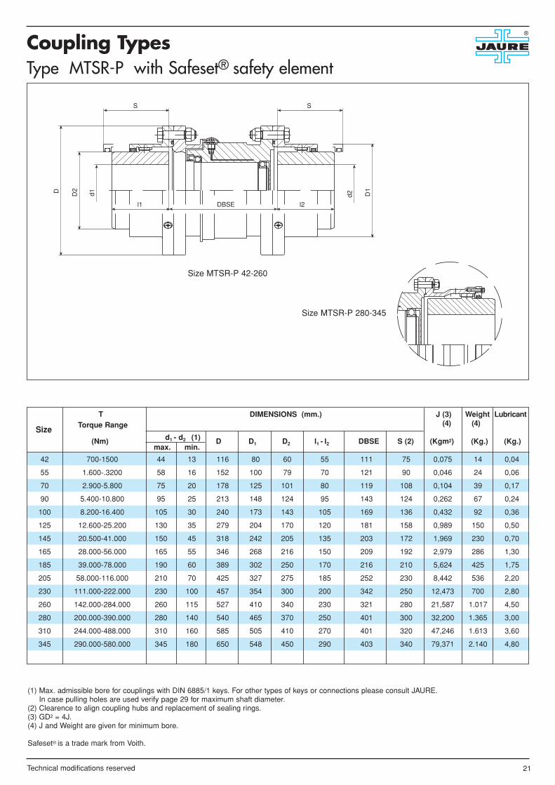
42 700-1500 44 13 116 80 60 55 111 75 0,075 14 0,04
55 1.600-.3200 58 16 152 100 79 70 121 90 0,046 24 0,06
70 2.900-5.800 75 20 178 125 101 80 119 108 0,104 39 0,17
90 5.400-10.800 95 25 213 148 124 95 143 124 0,262 67 0,24
100 8.200-16.400 105 30 240 173 143 105 169 136 0,432 92 0,36
125 12.600-25.200 130 35 279 204 170 120 181 158 0,989 150 0,50
145 20.500-41.000 150 45 318 242 205 135 203 172 1,969 230 0,70
165 28.000-56.000 165 55 346 268 216 150 209 192 2,979 286 1,30
185 39.000-78.000 190 60 389 302 250 170 216 210 5,624 425 1,75
205 58.000-116.000 210 70 425 327 275 185 252 230 8,442 536 2,20
230 111.000-222.000 230 100 457 354 300 200 342 250 12,473 700 2,80
260 142.000-284.000 260 115 527 410 340 230 321 280 21,587 1.017 4,50
280 200.000-390.000 280 140 540 465 370 250 401 300 32,200 1.365 3,00
310 244.000-488.000 310 160 585 505 410 270 401 320 47,246 1.613 3,60
345 290.000-580.000 345 180 650 548 450 290 403 340 79,371 2.140 4,80
D1
D2
S
d2
D d1
l1 l2DBSE
S
Size
T Torque Range
(Nm) D D1 D2 l1 - l2 DBSE S (2) (Kgm2) (Kg.) (Kg.)d1 - d2 (1)max. min.
Type MTSR-P with Safeset® safety element
DIMENSIONS (mm.) J (3) Weight Lubricant(4) (4)
(1) Max. admissible bore for couplings with DIN 6885/1 keys. For other types of keys or connections please consult JAURE.In case pulling holes are used verify page 29 for maximum shaft diameter.
(2) Clearence to align coupling hubs and replacement of sealing rings.(3) GD2 = 4J.(4) J and Weight are given for minimum bore.
Safeset® is a trade mark from Voith.
Size MTSR-P 42-260
Size MTSR-P 280-345

22
Coupling Types®
Technical modifications reserved
42 0.107 1.025 3.000 44 13 100 60 55 55 6 104 12 12 24 18 0,006 4,5 0,04
55 0.225 2.150 2.500 60 16 120 79 70 70 6 124 14 14 33 20 0,016 7,8 0,05
70 0.440 4.200 2.000 75 20 150 101 80 80 6 154 16 16 40 25 0,048 14,5 0,14
90 0.754 7.200 1.700 95 25 177 124 95 95 8 187 16 16 50 28 0,103 22 0,2
100 1.225 11.700 1.500 105 30 200 143 105 105 8 210 18 18 56 32 0,19 32 0,24
125 1.80 17.200 1.300 130 35 226 170 120 120 8 240 20 20 62 35 0,33 42 0,33
145 2.88 27.500 1.150 150 45 264 205 135 135 10 280 20 20 70 40 0,70 65 0,45
165 3.98 38.000 1.050 165 55 290 216 150 150 10 300 22 22 72 42 1,09 82 0,8
185 5.36 51.200 950 190 60 325 250 170 170 10 330 24 24 77 44 1,90 115 1,0
205 7.05 67.300 850 210 70 353 275 185 185 12 368 26 26 81 48 2,75 140 1,2
230 9.21 88.000 800 230 100 377 300 200 200 12 390 26 26 86 52 3,75 165 1,4
260 14.08 134.500 700 260 115 435 340 230 230 12 450 30 30 102 60 7,66 252 2,7
280 18.85 180.000 650 280 140 470 370 250 250 16 485 30 30 102 60 11,05 315 3,0
R
l 1 l 2a
d1
D1
D d2
A
P
h
C
Size
(1) (2) Speed (3)PN (KW) TN Nominal n max.
n(Nm ) (r.p.m.) D D1 l1 l2 a A h P R C (Kgm2) (Kg.) (Kg.)d1 - d2 (4)
max. min.
Type MTES disengaging coupling
DIMENSIONS (mm.) J (5) Weight Lubricant(6) (6)
(1) PN = Nominal Power in (Kw); n = r.p.m.(2) TN = Nominal Torque in Nm; During start up the coupling can be loaded at 200% of nominal torque capacity.(3) Consult JAURE for couplings operating at higher speeds.(4) Max. admissible bore for couplings with DIN 6885/1 keys. For other types of keys or connections please consult JAURE.
In case pulling holes are used verify page 29 for maximum shaft diameter.(5) GD2 = 4J.(6) J and Weight are given for minimum bore.

23
Coupling Types®
Technical modifications reserved
42 0.136 1.300 6.950 48 13 145 113 65 55 6 80 0,0175 7,3 0,07
55 0.262 2.500 6.150 60 16 164 126 80 70 6 90 0,0275 10,4 0,10
70 0.450 4.300 5.480 70 20 184 147 95 80 6 100 0,0475 15 0,12
90 0.733 7.000 4.580 85 25 220 176 112 95 8 130 0,1150 26 0,22
100 1.215 11.600 4.200 100 30 240 200 135 105 8 140 0,200 36 0,30
125 1.990 19.000 3.730 120 35 270 230 160 120 8 150 0,325 52 0,40
145 2.827 27.000 3.250 140 45 310 256 185 135 10 160 0,675 72 0,60
165 4.084 39.000 2.965 160 55 340 292 210 150 10 190 1,250 107 1,00
185 5.654 54.000 2.650 180 60 380 315 230 170 10 210 1,975 145 1,10
205 7.225 69.000 2.490 200 70 405 340 255 185 12 230 2,80 185 1,60
230 10.262 98.000 2.265 220 100 445 377 290 200 12 250 4,60 250 2,00
260 13.612 130.000 2.060 250 115 490 415 320 230 12 280 7,3 325 1,30
a
d1D2D
d2
D1
l1 l2
S
Size
(1) (2) Speed (3)PN (KW) TN Nominal n max.
n (Nm) (r.p.m.) D D1 D2 l1 - l2 a S(5) (Kgm2) (Kg.) (Kg.)d1 - d2 (4)
max. min.
Type MTN with covers
DIMENSIONS (mm.) J (6) Weight Lubricant (7) (7)
(1) PN = Nominal Power in (Kw); n = r.p.m.(2) TN = Nominal Torque in Nm; During start up the coupling can be loaded at 200% of nominal torque capacity.(3) Consult JAURE for couplings operating at higher speeds.(4) Max. admissible bore for couplings with DIN 6885/1 keys. For other types of keys or connections please consult JAURE.(5) Clearence to align coupling hubs and replacement of sealing rings. (6) GD2 = 4J.(7) J and Weight are given for minimum bore.

Equivalences between MT Gear couplingand previous JAURE Gear couplings Series.
Flange dimensions (mm.) A.G.M.A. standard
®
24 Technical modifications reserved
42 10 5 5
55 15 10 10
70 20 20 20
90 25 35 35
100 30 60 60
125 35 105 105
145 40 150 150
165 45 210 210
185 50 325 325
205 55 430 430
230 60 600 600
260 70 800 800
280 1.150 1.150
310 1.500
345 2.100
370 2.650
390 3.400
420 4.200
460 5.250
500 6.500
MT HA MS MN
• MT: with covers from 260 upwards.• MS: without covers from MS-5 up to MS-325. • MN: with covers for all sizes (MN=MS from MS-430 upwards).• HA according to AGMA standard for Flange dimensions.• MT according to AGMA standard from size 42 up to 260
included (except type MTN).
42 116 95.25 6 6.5 14 95.25 6 14 6.5 9 73 2
55 152 122.23 8 9.5 19 122.23 8 21 9.5 12.5 92 2.5
70 178 149.22 6 12.75 19 147.63 10 21 9.5 12.5 117 2.5
90 213 180.97 6 16 22 177.8 10 27 12.75 14 142 2.5
100 240 206.37 8 16 22 203.2 12 27 12.75 14 164 2.5
125 279 241.3 8 19 29 235.74 12 33.5 16 19.5 190 2.5
145 317.5 279.4 8 19 29 269.88 14 33.5 16 19.5 225 4.5
165 346 304.8 10 19 29 298.5 14 33.5 16 19.5 250 5
185 389 342.9 8 22.25 38 334.96 14 40 19 23.5 280 5
205 425 368.3 14 22.25 38 366.71 16 40 19 23.5 308 6
230 457 400 14 22.25 26 - - - - - 340 6
260 527 463.5 16 25.5 29 - - - - - 396 6
Size D D3 U = Quantity d3 T D4 Z = Quantity d4 d5 X D5 (H7) b
Sizes above MT-260 are not according to AGMA standard.Flange for exposed bolts.
Flange for shrouded bolts.

Technical modifications reserved 25
Special designs
Here below are some standard and special couplingpaterns manufactured by us. Do not hesitate consulting usfor any coupling solution. Our Engineering Department isat your service.
®
Type MTKMill Motor Coupling
Type MTSDHorizontal Floating shaft
Type MTPWith Flange
Type TEGear Coupling for lifting gear drums
Type MTAEWith Electrical insulation
Type MTENDisengaging Coupling

Technical modifications reserved26
Special designs®
Type MTELDisengaging Coupling
Type MTETDisengaging Coupling
Type MTCO specialTelescopic Coupling
Type MTVSVertical Coupling
Type MTLLimited end Float
Type MTFDDisc Brake Coupling
Type MTBCShear pin Coupling
Type MTDMMCombination gear-elastic coupling

Technical modifications reserved 27
Special designs®
Technical modifications reserved 27
Special designs®
Type MTBXSpacer Shear pin Coupling
Type MTBRXSpacer Shear pin Coupling
Type SIDMetallurgy Standard (F)
Type AVLEHigh Speed Oil Lubrication
Type AVLIHigh Speed Oil Lubrication
Type ALTSpindle Coupling (Rolling Mill)
Type ALDSpindle Coupling (Rolling Mill)
Type ALSTTelescopic Spindle Coupling (Rolling Mill)

Recommendations for shaft/bore fits
Critical Speeds
®
The following recommendations, according to ISO, are given for shaft/bores fits.
28 Technical modifications reserved
* The stresses on hub must be checked.
For other types of connections please consult our technical department.
h 6
k 6
m 6
n 6
p 6
u 6
v 6
x 6
TYPE OF FIT SHAFTTOLERANCES
BORETOLERANCES
Interferencefits withparallel
key
Shrink fits*withoutparallel
key
S 7
M 7
K 7
J 7
H 7
H 7
Critical speeds for spacer MTX coupling.
In order to check the critical speed of the spacer the following formula must be applied:
Where,
N = critical speed for the spacer coupling (rpm)L = spacer length (mm)do = Outside diameter of steel tube (mm)di = Inside diameter of steel tube (mm)
In order to avoid any lateral vibrations due to the spacer, the running speed must be at least 20% lower than thecritical speed.
N = 1,082 x 108 do2 + di2
L2

29
Keyway and puller hole data®
Technical modifications reserved
42 60 42 51 M6 9 1
55 79 55 67 M8 12 2
70 101 70 85 M10 15 2
90 124 85 105 M12 18 2
100 143 100 122 M14 21 2
125 170 120 145 M16 24 3
145 205 145 175 M16 24 3
165 216 155 185 M20 30 3
185 250 175 212 M20 30 3
205 275 195 235 M20 30 3
230 300 205 248 M24 36 4
260 340 240 290 M24 36 4
280 370 240 305 M30 45 4
310 410 260 335 M30 45 4
345 450 285 370 M30 45 4
370 490 310 400 M36 54 4
390 520 350 435 M36 54 4
420 560 380 470 M42 63 5
460 600 410 505 M42 63 5
500 650 440 545 M42 63 5
550 710 470 590 M48 72 5
590 760 510 635 M48 72 6
620 810 550 680 M48 72 6
650 840 580 710 M48 72 6
680 890 610 750 M56 84 8
730 950 640 795 M56 84 8
800 1.050 720 885 M56 84 8
D.B
.C.
D2
B
d1-d
2
Z x45°
t1
b
t2
M
r2
Second keyway on request
SizeD2 D. B. C. M B Z
d1 - d2
max.
(1) The tolerance zone for the hub keyway width b for parallel keys is ISO P9.
Pulling holes are supplied optionally. Please verify maximum bore (d1 - d2) when pulling holes are used..
Puller hole data (mm)
8-10 3 1.8 1.4 0.08-0.16 3 x 3
10-12 4 2.5 1.8 0.16-0.25 4 x 4
12-17 5 3 2.3 0.16-0.25 5 x 5
17-22 6 3.5 2.8 0.16-0.25 6 x 6
22-30 8 4 3.3 0.25-0.4 8 x 7
30-38 10 5 3.3 0.25-0.4 10 x 8
38-44 12 5 3.3 0.25-0.4 12 x 8
44-50 14 5.5 3.8 0.25-0.4 14 x 9
50-58 16 6 4.3 0.25-0.4 16 x 10
58-65 18 7 4.4 0.4-0.6 18 x 11
65-75 20 7.5 4.9 0.4-0.6 20 x 12
75-85 22 9 5.4 0.4-0.6 22 x 14
85-95 25 9 5.4 0.4-0.6 25 x 14
95-110 28 10 6.4 0.4-0.6 28 x 16
110-130 32 11 7.4 0.7-1.0 32 x 18
130-150 36 12 8.4 0.7-1.0 36 x 20
150-170 40 13 9.4 0.7-1.0 40 x 22
170-200 45 15 10.4 0.7-1.0 45 x 25
200-230 50 17 11.4 1.2-1.6 50 x 28
230-260 56 20 12.4 1.2-1.6 56 x 32
260-290 63 20 12.4 1.2-1.6 63 x 32
290-330 70 22 14.4 2-2.5 70 x 36
330-380 80 25 15.4 2-2.5 80 x 40
380-440 90 28 17.4 2-2.5 90 x 45
440-500 100 31 19.5 2-2.5 100 x 50
d1 - d2
above - to
Keyway acc. to DIN-6885/1 (mm)
b (1) t1 t2 r2 Key

1. INSTALLATION.1.1 Ensure that all the parts are clean.1.2 Apply a light coat of grease to the O-rings (6) and install them in the sleeves (2,3 or 4,5) grooves.1.3 Apply grease on the sleeves (2,3 or 4,5) teeth . Place the sleeves on the shafts , avoid damage of the O-rings (6).1.4 For sizes larger than MT-260 place only the covers (7) on the shafts, after the O-rings or seals (6) were greased orplaced in the cover (7) grooves.1.5 Heat the hubs (1) to 110º C prior to installing. Do not use an open flame burner.1.6 Install hubs (1) on their respective shafts with the longest chamfer hub end towards the machine bearing ( See fig.5,detail A ). Hub faces have to be flush with shaft end. In case of doubt , please contact us.1.7 Install units to be connected in place and and check the spacing “a” between hubs. See Fig.6 on Page 31 or appro-ved drawing for correct hub spacing “a” , according to coupling type. In case of doubt , please contact us.1.8 Align the two shafts , check alignment using a dial indicator. Alignment precision depends on running speed. ( SeeFig.8 on Page 32).1.9 Allow the hubs (1) to cool before installing the sleeves (2, 3 or 4, 5) over the hubs. Apply grease on coupling hub (1)teeth before installing the sleeves (2, 3 or 4, 5).1.10 Bolt up the sleeves with the recommended tightening torque (See Fig.6 on Page 31), after installing the O-ring (10)in place. Using grease on the O-ring is recommended. Make sure that flange lubrication holes, after mounting, are 90ºangle to each other.1.11 Remove both plugs (9) on the sleeve (2,3 or 4,5). As an approximate method proceed as follows : Turn the couplingso that the flange lubrication holes are in 130, 430 ,730, 1030 watch position. Take away the 130 and 730 plugs (9) and pump gre-ase into the 130 holes, until grease leaks out from the lower 730 ( See detail B ). During this process it is recommended toremove the 1030 plug to vent the interior. For grease quality and more accurate quantity see Fig.7 on Page 31. If runningconditions are different than the ones given in Fig.7 Page 31, consult us. For types , MTD, MTSR-P, MTX, MTXL, it isnecessary to lubricate each half coupling separately. Introduce the oil plugs (9). For coupling types MTV, MTS, MTCO, ver-tical and disengaging, please consult JAURE.
2. MAINTENACE.Every 3000 working hours. If longer periods are needed , contact us.Proceed as mentioned under 1.11.
3. DISASSEMBLY AND INSPECTION.Every 8000 working hours.3.1 Before moving the sleeves, clean the hub surfaces near the O-rings (6) of rust or dirt.3.2 Remove bolts (11) and the O-ring (10).3.3 Control gearing and sealing.3.4 Control alignment.3.5 Use new grease.
Installation and Maintenance Instructions(See coupling parts in page 6)
®
30 Technical modifications reserved
Fig. 5
130Ain
10 Bin30
"A"
45°
90°
730
Aout430
Bout
DETAIL A
DETAIL B

NORMAL SPEEDAND DUTY
NORMAL SPEEDAND HEAVYDUTY SERVICE
Amoco
Castrol
Cepsa-Krafft
Esso-Exxon
Fina
Klüber
Mobil
Shell
Texaco
Verkol
Amoco coupling grease
Spheerol BN 1
KEP 1
Unirex RS 460, Pen-0- Led EP
Ceran EP-0
Klüberplex GE 11-680
Mobilgrease XTC,
Mobiltemp SHC 460 spezial
Albida GC1
Coupling grease KP 0/1 K-30
Verkol 320-1 Grado 1
Klüberplex GE 11-680
Coupling grease KP 0/1 K-30
Coupling grease
Unirex RS-460
Klüberplex GE 11-680
Mobilgrease XTC
Coupling grease KP 0/1 K-30
Klüber
Texaco
HIGH SPEED1)
Amoco
Esso-Exxon
Klüber
Mobil
Texaco
Fig. 6
Fig. 7
31
Gap spacing “a” and flange bolt tightening torque
Recommended Lubricants & Quantity
®
Technical modifications reserved
Size a (mm.) Size a (mm.) Size a (mm.)
1) Tightening torque is given for dry tightening. If lubrication is used please consult JAURE.
1High speed is considered for periheral velocity above 80 meters / second.
Greases to be used between 0 º C and 100 º C.Couplings are supplied with protective grease but not with working grease.The teeth mesh has to be cleaned from any protective oil or grease prior to mounting.Before mounting , approx. 70 % of grease quantity shall be hand packed between hub and sleeve teeth and surrounding area. After mounting , theremaining (30%) of the grease shall be pumped into the flange lubrication holes.For speeds below 300 r.p.m consult our Technical Dep.At high temperature, low speed and reversing drive, more frequent lubrication is needed than the one recommended in these instructions.Overfilling the coupling with grease may result in equipment damage.
MT-42 8 MT-205 325 MT-460 760
MT-55 20 MT-230 325 MT-500 1.140
MT-70 68 MT-260 565 MT-550 1.140
MT-90 108 MT-280 375 MT-590 1.140
MT-100 108 MT-310 375 MT-620 1.800
MT-125 230 MT-345 660 MT-650 1.800
MT-145 230 MT-370 660 MT-680 1.800
MT-165 230 MT-390 760 MT-730 1.800
MT-185 325 MT-420 760 MT-800 1.800
Tightening Tightening TighteningSize Torque1) Size Torque1) Size Torque1)
(Nm) (Nm) (Nm)
Coupling type MT and MTN
MTN-42 6±1 MTN-145 10±2
MTN-55 6±1 MTN-165 10±3
MTN-70 6±2 MTN-185 10±3
MTN-90 8±2 MTN-205 12±3
MTN-100 8±2 MTN-230 12±3
MTN-125 8±2 MTN-260 12±3
Size a (mm.) Size a (mm.)
MTN-42 39 MTN-145 108
MTN-55 39 MTN-165 108
MTN-70 39 MTN-185 328
MTN-90 69 MTN-205 328
MTN-100 69 MTN-230 328
MTN-125 69 MTN-260 376
Tightening TighteningSize Torque1) Size Torque1)
(Nm) (Nm)
MT-42 6±1 MT-205 12±3 MT-460 20±4
MT-55 6±1 MT-230 12±3 MT-500 25±4
MT-70 6±2 MT-260 12±3 MT-550 25±4
MT-90 8±2 MT-280 16±3 MT-590 25±4
MT-100 8±2 MT-310 16±3 MT-620 30±6
MT-125 8±2 MT-345 16±3 MT-650 30±6
MT-145 10±2 MT-370 20±4 MT-680 30±6
MT-165 10±3 MT-390 20±4 MT-730 30±6
MT-185 10±3 MT-420 20±4 MT-800 30±6

32
Alignment precision
®
Technical modifications reserved
MT-42 0.04 MT-205 2.2 MT-460 11.5
MT-55 0.06 MT-230 2.8 MT-500 11.5
MT-70 0.17 MT-260 4.5 MT-550 14.5
MT-90 0.24 MT-280 3.0 MT-590 23
MT-100 0.36 MT-310 3.6 MT-620 23
MT-125 0.50 MT-345 4.8 MT-650 30
MT-145 0.70 MT-370 5.0 MT-680 36
MT-165 1.30 MT-390 9.0 MT-730 38
MT-185 1.75 MT-420 9.8 MT-800 46
Size 2Qty (kg) Size 2Qty (kg) Size 2Qty (kg)
2Quantity per complete coupling for MT, MTL, MTK, MTBR, MTFD, MTFS, MTFE, MTF.
For types MTD, MTX, MTXL, MTBRX, add the given quantity divided by 2 at each half. Ex. MTX-125: 0,25 kg at each half.For types MTS, MTCO, vertical couplings and disengaging couplings consult our Technical Dep.
Z
Y
aX(T
.I.R
.)
42 - 90 0.25 0.25 0.25 0.25 0.25 0.25 0.15 0.20 0.08 0.10
100 - 185 0.50 0.60 0.50 0.60 0.25 0.35 0.15 0.20 0.08 0.10
205 - 420 0.90 1.00 0.50 0.75 0.25 0.35 0.15 0.20 - -
420 - 800 1.50 1.50 1.00 1.00 0.50 0.50 - -
0 - 250 250 - 500 500 - 1000 1000 - 2000 2000 - 4000
X max. (Y-Z) X max. (Y-Z) X max. (Y-Z) X max. (Y-Z) X max. (Y-Z) (mm.) mm. (mm.) mm. (mm.) mm. (mm.) mm. (mm.) mm.
Types Speed r.p.m.
MT
Fig. 7 (cont.)
Fig. 8
Recommended Lubricants & Quantity (cont.)
A better alignment than the one given in this table will increase coupling life and reduce the reaction forces in shafts and bearings.
MTN-42 0,07 MTN-145 0,60
MTN-55 0,1 MTN-165 1,00
MTN-70 0,12 MTN-185 1,10
MTN-90 0,22 MTN-205 1,60
MTN-100 0,3 MTN-230 2,00
MTN-125 0,4 MTN-260 1,30
Size Qty (kg) Size Qty (kg)

®
Applications
1
2
4
3
5
76
1
3
4
5
6
7
2& Brake disc gear coupling MTFS in a craneapplication.
Special MT-460 for a dredger pump.
MT-550 for Mining Equipment.
Construction & Maintenance of Spindle GearCouplings.
SID-650 for Rolling Mill (MT equivalent size biggerthan MT-800).
Vertical & horizontal spindle gear couplings forrolling mill stands.

Special MTFS-125 couplings for windmills.
Safety gear coupling, type MT-345-SE 30(disengaging torque 265 KNm)
Special MT coupling for Marine Applications.
Machining of gear rims for Windmills.
& Traction gear coupling, Model FE-255 forRailway application.
MT gear couplings for screw conveyors.
Applications
2
1
3
5
4
®
6
7
1
2
3
4
5
7
65

Special finish bore available: flatsurfaces, hidraulic shrink fit, splines,tangencial keyways.
& Special MTXL-125 inductionhardened coupling with spacerfor compressors.
4
1
2
3
6
5
7
8
9
®
1
2 3
Alloyed steel and nitridedMT-460
Torsion shaft MT coupling &special MT for Paper Industry.
Spacers for MTX-550 andgear hub.
Production of standard MTseries.
Special MTX-420 with spacer& angular adjustmentpositioning.
Big gear coupling(o.d. > Ø 1800 mm) for steelplant converter.
4
5
6
7
8
9

JAURE, S.A.Ernio bidea, s/n - 20150 ZIZURKIL (Guipúzcoa) SPAINPhone: +34 943 69.00.54 - Fax: +34 943 69.02.95 Fax Tech. Dept.: +34 943 69.03.17 Post address : P.O. Box, 47 20150 VILLABONA (Guipúzcoa) SPAINe-mail:[email protected] • http://www.jaure.com
PAMPLONAVITORIA
VILLABONAZIZURKIL
TOLOSA
SAN SEBASTIAN
BIARRITZ
BILBAO
JAURE, S.A. - Couplings and transmission elements
MT crowned tooth gear coupling. LAMIDISC® all steel disc coupling.
JAUFLEX® elastic coupling.RECORD flexible spring coupling.
Gear spindles for rolling mills. High speed disc coplings LAMIDISC®HP.
Barrel coupling TCB® / TCB-s®.
IXILFLEX® link type elastic coupling.
Composite link coupling COMPOLINK®