n o i t a t r e o n p i s a n a (8 0 m r 5 .0 f in 8 t 5 o ... steel erection structural steel...
TRANSCRIPT


2
ESTIMATED QUANTITIES
ITEM NO. DESCRIPTION UNIT
BL
TB
LT
JK
OJ
KO
10/2015
10/2015
ES
TI
MA
TE
D
QU
AN
TITIE
S
ESTIMATED QUANTITIES
ITEM NO. DESCRIPTION UNITQUANTITY QUANTITY
(310 CY)
(395 CY)
(6,275 LB)
(6,275 LB)
(3,948 EA)
(6,275 LB)
(6,275 LB)
(6,275 LB)
(6,275 LB)
(6,275 LB)
(515 LF)
(1,450 SY)
(420 LF)
659.10
656.75
652.41
652.38
652.36
652.35
652.34
652.33
652.312
645.1061
639.18
634.712
634.711
634.160
631.22
631.172
631.12
631.11
631.10
629.05
627.78
627.77
627.733
627.51
626.35
Mobilization
Temporary Soil Erosion and Water Pollution Control
Portable-Changeable Message Sign
Flaggers
Maintenance of Traffic Control Devices
Construction Signs
Cone
Drum
Type III Barricade
Relocate Existing Sign Assembly and Post
Field Office, Type A
Ornamental Light, Install Only
Ornamental Light Fabricated and Delivered
Highway Lighting
Front End Loader (including operator)
Truck-Large (including operator)
All Purpose Excavator (including operator)
Air Tool (including operator)
Air Compressor (including operator)
Hand Labor, Straight Time
Temporary Pavement Marking Line, White or Yellow
Removing Existing Pavement Marking
4" White of Yellow Painted Pavement Marking Line
6" Temporary Pavement Tape, Yellow or White
Controller Cabinet Foundation
1
1
3
600
210
745
20
20
1
7
1
4
4
1
20
20
10
10
10
20
730
170
1,300
1,220
1
LS
LS
EA
HR
CD
SF
EA
EA
EA
EA
EA
EA
EA
LS
HR
HR
HR
HR
HR
HR
LF
SF
LF
LF
EA
Erosion Control Mix
Mulch
Seeding Method Number 3
Seeding Method Number 2
Loam
Erosion Control Blanket
Plain Riprap
Reset Curb Type 1
Terminal Curb Type 1 - 8 foot - Circular
Terminal Curb Type 1 - 8 foot
Curb Ramp Detectable Warning Field
Guardrail 350 Flared Terminal
Reflectorized Flexible Guardrail Marker
Terminal End - Single Rail - Galvanized Steel
Anchorage Assembly
Guardrail Type 3c - Over 15 ft Radius
Guardrail Type 3c - Single Rail
Bridge Transition - Type I
Glass Fiber Reinforced Polymer, Placing
Glass Fiber Reinforced Polymer, Fabricated and Delivered
Work Zone Crash Cushions
Permanent Concrete Transition Barrier
Temporary Concrete Barrier
Temporary Structural Support
Steel Bearings, Expansion, Rocker
Bearing Installation
Remove, Refurbish, & Reset Expansion Bearing
Bridge Joint Modification Type 5
Repair of Vertical Surfaces < 8 inches
Repair of Upward Facing Surfaces - to Reinforcing Steel
Protective Coating for Concrete Surfaces
Curing Box for Concrete Cylinders
Not Separated
Special Detour, 56 foot Roadway With Vehicular and Pedestrian Traffic
Steel Bridge Railing, 4 bar
Galvanizing
Disposal of Special Waste or Hazardous Waste
Containment and Pollution Control Measures
Surface Preparation of Existing Structural Steel
Field Paint Existing Structural Steel
Shear Connectors
Structural Steel Erection
Structural Steel Fabricated and Delivered
Epoxy-Coated Reinforcing Steel, Placing
Epoxy-Coated Reinforcing Steel, Fabricated and Delivered
Concrete Fill
Structural Concrete Roadway and Sidewalk Slab on Steel Bridges
Structural Concrete, Abutments and Retaining Walls
Temporary Pavement
Bituminous Tack Coat, Applied
Hot Mix Asphalt, 12.5 mm Nominal Maximum Size (Base and Intermediate Course)
Hot Mix Asphalt, 9.5 mm Nominal Maximum Size (Shimming)
Hot Mix Asphalt, 9.5 mm Nominal Maximum Size (Sidewalks, Drives, Islands & Incidentals)
Hot Mix Asphalt, 12.5 mm Nominal Maximum Size (Polymer Modified)
Hot Mix Asphalt, 12.5 mm Nominal Maximum Size
Aggregate Base Course - Type B
Aggregate Subbase Course - Gravel
Common Excavation
Removing Pavement Surface
Removing Existing Structural Concrete
Removing Existing Superstructure Property of Contractor
619.1401
619.1201
618.141
618.14
615.07
613.319
610.08
609.38
609.2381
609.238
608.26
606.79
606.353
606.265
606.259
606.232
606.23
606.1721
530.31
530.30
527.34
526.34
526.301
524.301
523.5304
523.52
523.31
520.245
518.60
518.50
515.21
514.06
510.10
507.0831
506.9103
506.191
506.18
506.17
506.142
505.08
504.71
504.70
503.15
503.14
502.565
502.26
502.21
461.131
409.15
403.213
403.211
403.209
403.2081
403.208
304.15
304.10
203.20
202.202
202.12
202.10
5
2
1
1
13
44
19
260
1
2
13
2
6
1
1
57
220
4
74,800
74,800
4
4
1
1
14
14
1
2
10
10
1
1
1
1
1
1
1
1
1
1
1
1
48,800
48,800
6
1
10
265
50
105
10
34
67
8
140
110
310
420
6
1
CY
Unit
Unit
Unit
CY
SY
CY
LF
EA
EA
SF
EA
EA
EA
EA
LF
LF
EA
LF
LF
Unit
EA
LS
LS
EA
EA
LS
EA
SF
SF
LS
EA
LS
LS
LS
LS
LS
LS
LS
LS
LS
LS
LB
LB
CY
LS
CY
T
Gal
T
T
T
T
T
CY
CY
CY
SY
CY
LS
DE
SIG
N-
DE
TAIL
ED
BY
DA
TE
PR
OJ.
MA
NA
GE
R
SHEET NUMBER
FIE
LD
CH
AN
GE
S
RE
VISIO
NS
1
RE
VISIO
NS
2
RE
VISIO
NS
3
RE
VISIO
NS
4
CH
EC
KE
D-
RE
VIE
WE
D
HIG
HW
AY
Divisio
n:
Filena
me:...\
BRID
GE\
MS
TA\
002
_Q
uantities.d
gn
Userna
me:
Date:1
2/11/2
015
OF
DE
SIG
N2-
DE
TAIL
ED
2
DE
SIG
N3-
DE
TAIL
ED
3
BRID
GE P
LA
NS
ST
AT
E O
F M
AIN
E
DE
PA
RT
ME
NT O
F T
RA
NSP
OR
TA
TIO
N
DA
TE
SIG
NA
TU
RE
P.E.
NU
MB
ER
UP
PE
R
CA
NA
L
BRID
GE
OX
FO
RD
CO
UN
TY
WIN
19058.0
0B
RID
GE #
5619
R
UM
FO
RD
37
HE
C
STP-1
905(8
00)
OV
ER
MIL
L
CA
NA
L

GENERAL NOTES
26.
25.
24.
23.
22.
21.
20.
19.
18.
17.
16.
15.
14.
13.
12.
11.
10.
9.
8.
7.
6.
5.
4.
3.
2.
1.
All dimensions shown in the plans are horizontal or vertical at 45° F, unless noted otherwise.
- Top of abutment backwalls and to one foot below the top of backwalls on the back side.
- Concrete wearing surfaces,
- All exposed surfaces of Concrete Transition Barriers,
- Fascia down to drip notch,
- All exposed surfaces of concrete curbs, sidewalks, and light pole pedestals,
Protective Coating for Concrete Surfaces shall be applied to the following areas:
Geotextile shall be incidental to Riprap.
Riprap installed for slope protection shall be placed on a Non-Woven Erosion Control Geotextile. Payment for Erosion Control
costs required to remove and dispose of the existing bridge will be considered incidental to the bridge removal pay item.
regulation is available at MaineDOT's offices on Child Street in Augusta. Payment for all labor, materials, equipment and other
Department of Environmental Protection's "Maine Hazardous Waste management Regulations," Chapter 850. A copy of this
the bridge component including lead-coated steel. The Contractor shall recycle or reuse the steel in accordance with the Maine
the components of the existing bridge and any hazardous waste generated as a result of the storage, recycling or disposal of
Once the portions of the existing bridge are removed, the Contractor is solely responsible for the care, custody and control of
Contractor is responsible for implementing appropriate OSHA mandated personal protection standards related to this process.
management and disposal of all lead-contaminated hazardous waste generated by the process of demolishing the bridge. The
the existing bridge are coated with a lead-based paint system. The contractor is responsible for the containment, proper
Identified portions of the existing bridge shall be removed by and become the property of the Contractor. The steel portions of
pay item.
work necessary for developing, submitting and finalizing the Demolition Plan will be considered incidental to the bridge removal
Contractor until the Resident has reviewed the Bridge Demolition Plan for appropriateness and completeness. Payment for all
superstructure, and a subset of existing bearings. No work related to the removal of these items shall be undertaken by the
wearing surface, bridge railing, existing lighting, portions of the abutment backwalls, expansion joints, portions of the steel
work. The plan shall outline the methods and equipment to be used to remove and dispose of the existing concrete deck and
The Contractor shall submit a Bridge Demolition Plan to the Resident at least 10 business days prior to the start of demolition
Curb Ramp Detectable Warning Fields shall be installed at the ends of all pedestrian ramps.
Connections for proposed guardrail to existing guardrail will be considered incidental to 606 Items.
to be considered incidental to the guardrail items.
Holes created by Guardrail removal will be filled and compacted with approved materials as directed by the Resident. Payment
incidental to the guardrail items.
All existing guardrail shall be removed and shall become the property of the contractor. Removal and disposal shall be considered
Two Reflectorized Flexible Guardrail Markers (Item 606.353) shall be installed at each guardrail end.
guardrail.
A NCHRP 350 compliant guardrail end treatment shall be installed concurrently with the placement of each section of beam
with an embedment of 4.5 feet. Payment will be considered incidental to the guardrail pay items.
Guardrail posts as shown in the Standard Details shall be modified from the indicated length of 6 feet to a length of 7 feet,
Payment will be made under 656.75 ' Temporary Soil Erosion and Water Control, Lump sum.'
Temporary Erosion control measures shall be maintained as specified in the Soil Erosion and Water Pollution Control Plan.
for Erosion Control & Sediment Control, February, 2008.
All work shall be done in accordance with the Maine Department of Transportation's (Maine DOT's) Best Management Practices
required to make repairs shall be at the Contractor's expense.
Equipment, Personnel, or Operation shall be repaired to the satisfaction of the Resident. All work, equipment, and materials
Any damage to the roadway, sideslopes, existing structure to remain, or other on-site infrastructure caused by the Contractor's
equipment rental items.
No separate payment for superintendent or foreman will be made for the supervision of equipment being paid for under the
inches or less thick will be made under appropriate equipment rental items.
removing existing pavement, grubbing, shaping, ditching, and compacting the existing subbase and layers of new subbase 6
In areas where the Resident directs the Contractor not to excavate to the subgrade line shown on the plans, payment for
Do not excavate for Aggregate Base Course where existing material is suitable as determined by the Resident.
utilized on all guardrail slopes.
Unless otherwise noted, Seeding Method No. 2 shall be utilized on all non-guardrail slopes. Seeding Method No. 3 shall be
Place loam 2 inches deep on all new or reconstructed sideslopes or as directed by the Resident.
Payment for clearing will be considered incidental to related Contract items.
The clearing limits as shown on the plans are approximate. The exact limits will be established in the field by the Resident.
Place a 24 inch wide strip if Erosion Control Blanket on the side slopes along the top of riprap and behind the wingwalls.
During construction, the bridge will be closed to traffic for the time period specified in the Special Provisions.
For easements, construction limits, and right-of-way lines, refer to Right of Way Map.
The contractor shall be responsible for costs associated with coordination with the utility companies, if needed.
- Rumford Sewer
- Rumford-Mexico Water District
- Maine Fiber
- Oxford Networks
- Time Warner Cable
- Central Maine Power
- Fairpoint Communications
are as follows:
All utility facilities shall be adjusted by the respective utilities unless otherwise noted. The utilities involved in this contract
33.
32.
31.
30.
29.
28.
27.
any alterations which may have been made to the bridge during its life span.
as prepared for the construction of the bridge. It is very unlikely that the plans will show any construction field changes or
The existing bridge plans may be accessed at the MaineDOT web address. The plans are reproductions of the original drawings
http://www.maine.gov/mdot/contractors/#projecttbl
Project information referred to below may be accessed at the following MaineDOT web address:
responsible for field verifying all dimensions prior to fabrication.
drawings; no field survey or verification measurements were obtained in preparation of these details. The Contractor is
Details and dimensions of the existing bridge provided herein are based upon existing design plans and existing shop
related 506 Contract items.
All debris shall be removed from the bridge bearings and bearing seat areas. This work shall be considered incidental to the
Provision 506, Lead Abatement and Surface Preparation.
Proposed connection contact surfaces on the existing steel girders shall be cleaned according to the requirements of Special
made in accordance with Standard Specifications Section 109.7, Equitable Adjustments to Compensation.
c. If a design change results in changes to estimated quantities for Lump Sum pay items, price adjustments will be
will be followed.
b. If other Contract Documents specifically allow a change in payment for a Lump Sum pay item, those requirements
of Items, will take precedence.
a. If a Lump Sum pay item is eliminated, the requirements of Standard Specifications Section 109.2, Elimination
quantities, except as follows:
addition or reduction in payment to the Contractor if the actual final quantities are different from the provided estimated
MaineDOT for informational purposes only. Lump Sum pay items will be paid for at the Contract Bid amount, with no
Quantities included for pay items measured and paid for by Lump Sum are estimated quantities and are provided by
Resident.
Existing Abutments shall be repaired in accordance with Section 518 of the Standard Specifications and as directed by the
GE
NE
RA
L
NO
TE
S
JR
HJ
RH
JK
OH
EC
9/2015
9/2015
3
DE
SIG
N-
DE
TAIL
ED
BY
DA
TE
PR
OJ.
MA
NA
GE
R
SHEET NUMBER
FIE
LD
CH
AN
GE
S
RE
VISIO
NS
1
RE
VISIO
NS
2
RE
VISIO
NS
3
RE
VISIO
NS
4
CH
EC
KE
D-
RE
VIE
WE
D
HIG
HW
AY
Divisio
n:
Filena
me:...\
MS
TA\
003
_General_
Notes 1.d
gn
Userna
me:
Date:1
1/19/2
015
OF
DE
SIG
N2-
DE
TAIL
ED
2
DE
SIG
N3-
DE
TAIL
ED
3
BRID
GE P
LA
NS
ST
AT
E O
F M
AIN
E
DE
PA
RT
ME
NT O
F T
RA
NSP
OR
TA
TIO
N
DA
TE
SIG
NA
TU
RE
P.E.
NU
MB
ER
UP
PE
R
CA
NA
L
BRID
GE
OX
FO
RD
CO
UN
TY
WIN
19058.0
0B
RID
GE #
5619
R
UM
FO
RD
37
HE
C
STP-1
905(8
00)
OV
ER
MIL
L
CA
NA
L

W
Sill EL
W
Sill EL
505
505
505
510
510
510
515
515
515
520520
525
DIA
GO
NAL P
AR
KIN
G
14"
MAPLE
12"
MAPLE
.
FAIR
POIN
T
& TIM
E
WAR
NER
.
ELECTRIC
METER B
OX
.
14"
MAPLE
NO P
AR
KIN
G
CO
NC
24" C
MP
3X5
X3
12"
MAPLE
.
PAVED
.
ROUTE SIGN
.
BUSIN
ESS
MET
AL S
HOP 1 ST
OR
Y
CO
NC
3X3
X2
PLUNGE POOL
24"
BEEC
H
BO
TT
EM
OF
BA
NK
.
PA
VE
D
YAR
D
CO
NC
.
FAIR
DIA
GO
NAL P
AR
KIN
G
24" C
MP
NY
NE
X 900 1
CMP 12
3X3
PL
AN
TE
R
6IN
3X3X2
AB
AN
DO
NED
INFO
CO
NC
.
NODE 7192
.
15
MIN P
AR
KIN
G
PAVED
DRIV
E
CO
NC
2X2X2
DAN
GER IN
FO
PA
RKIN
G
.
CO
NC.+B
RIC
K
WALL
TO
P
OF
BA
NK
2X2X2
.
.
JOINT CMP 13 NET 2
2 1/
2 S
NO PARKING
PAVED
DRIV
E
12"
AS
H
.
6' DIA BUSH
.
CMP 11 NET 1 3
BRIC
K
PAVED
CA
NAL S
T
12"
AS
H
.
3 P
AR
ALLEL P
AR
KIN
G
10' DIA B
US
H
CANAL BR
.
JOIN
T C
MP 4
NY
NEX 4
.
PAVED
10' DIA BUSH
APTS 3 ST
OR
Y
.
SNOWMOBILE XING PAVED
WO
OD
S
EN
TR
AN
CE
.
BUSINESS DISTRICT
.
PAVED
SIGN
SIGN
CLUMP
CEDAR
12"
CLUMP
CEDAR
12"
CM
P J1 1
TWIN
AS
H12"
CMP 2 / VZ 1 1/
2
15
MIN P
AR
KIN
G
NO LEFT T
UR
N
PIPECONC
1S J1 1CMP
PAR
KIN
G
8
DIA
GO
NAL
NETT 2
CMP J2 1/
2
NETT 900/5CMP 16S J16
NETT 900/5CMP J16
COVERCONC2+
00
3+00
4+00 5+00 6+00 7+00
8+00
9+00
PC
=
ST
A. 2+
01.8
1
PC
=
ST
A. 6+
82.7
5
PT
=
ST
A.
8+
86.5
3
E = 12.32'
T = 86.84'
L = 169.06'
R = 300.00'
PI = 2+88.65
CURVE DATA #1
E = 4.16'
T = 102.11'
L = 203.77'
R = 1250.00'
PI = 7+84.86
CURVE DATA #2
ROUTE 108
ROUTE 108
21+00
22+00
23+00
24+00
PO
B = STA. 2
0+22.05
PT = STA. 3
+70.87
RD
RAIL
EAS
E
LIMITS
D.O.T FIL
E
NO. 9
-305, M
AR
CH 1999
AC
QUIR
ED
AS P
ART
OF
EXIS
TIN
G
GU
AR
DR
AIL E
ASE.
S.H.C. FILE NO. 9-71,
JANUARY 1953ACQUIRED AS PART OF 18"X118
' A.C.C.M.P.EXISTING DRAINAGE EASE.
EASEMENTPARKING AREA
DE
SIG
N-
DE
TAIL
ED
BY
DA
TE
PR
OJ.
MA
NA
GE
R
SHEET NUMBER
FIE
LD
CH
AN
GE
S
RE
VISIO
NS
1
RE
VISIO
NS
2
RE
VISIO
NS
3
RE
VISIO
NS
4
CH
EC
KE
D-
RE
VIE
WE
D
HIG
HW
AY
Divisio
n:
Filena
me:...\
HIG
HW
AY\
MS
TA\
004
_H
DPla
n_
01.d
gn
Userna
me:
Date:1
1/13/2
015
OF
DE
SIG
N2-
DE
TAIL
ED
2
DE
SIG
N3-
DE
TAIL
ED
3
BRID
GE P
LA
NS
ST
AT
E O
F M
AIN
E
DE
PA
RT
ME
NT O
F T
RA
NSP
OR
TA
TIO
N
DA
TE
SIG
NA
TU
RE
P.E.
NU
MB
ER
UP
PE
R
CA
NA
L
BRID
GE
OX
FO
RD
CO
UN
TY
WIN
19058.0
0B
RID
GE #
5619
R
UM
FO
RD
37
HE
C
STP-1
905(8
00)
OV
ER
MIL
L
CA
NA
L
Flo
w
Upper Canal Bridge
Guardrail
Existing
Connect To
Sta. 4+20
É Brg. Abut. No. 2
Sta. 5+00
É Pier
No. 2
wekS
°54
Sta. 6+00
É Pier
No. 1
Scale of Feet
PLAN
25 0 25 50
80'-0"100'-0"80'-0"
Station StationTo
Station StationTo
7+04, LT 7+50, LT
Item 610.08 - Plain Riprap
Station StationToOffset Offset Length
Station StationTo
Item 606.232 - Guardrail Type 3c - Over 15 ft Radius
Offset Offset Length Radius
Item 606.23 - Guardrail Type 3c - Single Rail
Station StationToOffset Offset
Item 606.1721 - Bridge Transition - Type IStation Offset
Item 606.79 - Guardrail 350 Flared Terminal
Station Offset
8+71.78 28.02' LT
Item 606.259 - Anchorage Assembly
Station Offset
Item 606.265 - Terminal End - Single Rail - Galvanized Steel
Station StationTo
Item 609.2381 - Terminal Curb Type 1 - 8' - Circular
Offset Offset Radius
20+99.00 24.76' RT 21+06.00 20.97' RT 24.00'
Station StationTo
Station StationTo
Item 618.14 - Seeding Method Number 2
Item 618.141 - Seeding Method Number 3
Station StationToOffset Offset
Station StationToOffset Offset
Item 609.238 - Terminal Curb Type 1 - 8'
Item 609.38 - Reset Curb Type 1
To Peru
To Hanover
Route 108
8+02.59
7+11.91
14.00' RT
14.00' LT
14.00' RT
14.00' LT
8+10.50
7+20.00
21+12.00
20+99.00
6+97.79
6+69.54
3+70.82
3+50.00
19.74' RT
24.76' RT
14.00' LT
14.00' RT
14.00' RT
14.77' RT
21+28.7
4+30.47
7+11.91
8+02.59
4+02.16
3+70.82
19.5' RT
14.00' LT
14.00' LT
14.00' RT
14.00' RT
14.00' RT
Length
16.7'
40.15'
13.96'
134.40'
31.59'
21.88'
8+71.78 28.02' LT
Limit of
Work
Sta. 2
+85.4
5
Limit of W
ork
Sta. 2
1+28.7
Limit o
f
Work
Sta. 8
+71.7
8
6+93.95
3+25.59
19.00' RT
22.49' RT
7+01.17
6+61.14
4+19.15
3+78.63
18.87' LT
19.00' RT
22.66' LT
19.00' RT
7+21.96
6+82.75
4+38.86
3+99.11
19.00' LT
19.00' RT
19.00' LT (19.00' Radius)
19.00' RT
4+19.15
8+48.89
22.66' LT
18.80' LT
21+12.62
8+71.78
24.71' RT
28.02' LT
31.25'
25.00'
19.00'
30.00'
21+12.62
8+26.31
7+21.96
6+82.75
3+70.87
3+25.59
24.71' RT
19.00' LT
19.00' LT
19.00' RT
19.00' RT
22.49' RT
21+35.7
8+48.89
8+26.31
6+93.95
3+78.63
3+70.87
25.2' RT
18.80' LT
19.00' LT
19.00' RT
19.00' RT
19.00' RT
23.0'
22.24'
102.76'
12.50'
7.77'
48.48'
7+15, LT
6+68, RT
2+83, RT
8+65, LT
7+64, RT
3+97, RT
14.00' LT
PT 4+30.36
R = 24.00'
43.67' RT
Sta. 21+13.77
19.68' RT
PC 21+13.43
Mill Canal
Canal St.
21+12, RT
7+30, RT
21+36, RT
8+11, RT
21+00, RT
7+50, LT
6+59, RT
2+91, RT
21+36, RT
8+00, LT
7+30, RT
3+97, RT
Begin F
ull R
econstr
uction
End 4"
Mill and
Overla
y
Sta. 3
+85.0
0
Sta. 20+22.05 Canal Street
Sta. 3+35.23 Route 108 =Matc
h
Existin
g Pave
ment
End 2" M
ill and
Overla
yE
nd
Project
Sta. 8
+00.0
0
Begin 4" M
ill and
Overla
yE
nd
Full R
econstr
uctio
nSta. 7
+15.0
0
Begin 2" M
ill and
Overla
yE
nd 4" M
ill and
Overla
ySta. 7
+60.0
0
DYCL
SWEL
SWEL
GE
NE
RA
L
PL
AN
JR
H
HE
C
9/2015
9/2015
TS
K
RE
M
Clearing
4
Begin 4"
Mill and
Overla
y
Matc
h
Existing Pave
ment
Begin Project
Sta. 3
+50.0
0
Ë Canal Street
(By Others)
RemoveSta. 6+80
É Brg. Abut. No. 1
Begin SWEL
Sta. 4+25.00
Begin DYCL
STA 3+90.00
É Construction
Sheet 23)
(See Note 11 on
Controller Cabinet

2+00 3+00 4+00 5+00 6+00 7+00 8+00 9+00
2+00 3+00 4+00 5+00 6+00 7+00 8+00 9+00
PV
C =
ST
A. 3
+00.0
0
ELE
V. =
506.6
8
PVI =
ST
A. 3
+50.0
0
ELE
V. =
507.0
3
PVT =
ST
A. 4+0
0.0
0
ELE
V. =
508.2
8
PV
C =
ST
A. 7+0
0.0
0
ELE
V. =
515.7
8
PVI =
ST
A. 7+5
0.0
0
ELE
V. =
517.0
3
PV
T =
ST
A. 8+0
0.0
0
ELE
V. =
519.5
0
G = 2.50%
V.C.L. = 100'
G1 = 0.71%
G2 = 2.50%
V.C.L. = 100'
G1 = 2.50%
G2 = 4.94%
EL. 506.6
8
EL. 506.9
1
EL. 507.2
5
EL. 507.7
1
EL. 508.2
8
EL. 508.9
1
EL. 509.5
3
EL. 510.16
EL. 510.7
8
EL. 511.4
1
EL. 512.0
3
EL. 512.6
6
EL. 513.2
8
EL. 513.9
1
EL. 514.5
3
EL. 515.16
EL. 515.7
8
EL. 516.4
8
EL. 517.3
4
EL. 518.3
4
EL. 519.5
0
EL. 506.3
8
EL. 506.4
4
EL. 506.4
8
EL. 506.6
8
EL. 506.9
0
EL. 507.2
7
EL. 507.6
9
EL. 508.1
3
EL. 515.5
1
EL. 516.3
6
EL. 517.2
9
EL. 518.3
7
EL. 519.5
0
EL. 520.7
3
EL. 522.1
7
EL. 523.7
5
480
485
490
495
500
505
510
515
520
525
530
535
540
545
480
485
490
495
500
505
510
515
520
525
530
535
540
545
EL. 525.4
4
EL. 506.2
3
40'-0"
2" H.M.A.
45'-0"
4" H.M.A.
35'-0"
8" H.M.A.
Course Type - B
Aggregate Base
Course Type - B
Aggregate Base
475
470
465
475
470
465
Span No. 1
80'-0"
Span No. 2
100'-0"
Span No. 3
80'-0"
Approach Slab
Existing
Approach Slab
Existing
Pier No. 2
Existing
Pier No. 1
Existing
Existing Grade
Existing Grade
(Exp.)
Sta. 4+20
É Brg., Abut. No. 2
(Exp.)
Sta. 5+00
É Pier No. 2
(Fixed)
Sta. 6+00
É Pier No. 1
(Exp.)
Sta. 6+80
É Brg., Abut. No. 1
Existing Beams
Water Elev.
Approx. Normal
ST
A. 3
+85.0
0
Begin Full R
econstr
uction
End 4"
Mill and
Overla
y
ST
A. 3
+50.0
0
Abutment No. 2
Existing
HLSD = 469'
HLSD = 6987'
E = 0.22'
E = 0.30'
ST
A. 7+15.0
0
Begin 4"
Mill and
Overla
yEnd Full R
econstr
uction
ST
A. 7+6
0.0
0
Begin 2"
Mill and
Overla
yEnd 4"
Mill and
Overla
y
ST
A. 8+0
0.0
0
Abutment No. 1
Existing
Matc
h Existing Pave
ment
End 2"
Mill and
Overla
yEnd Project
ST
A. 2
+85.4
5
Limit of
Work
ST
A. 8+7
1.78
Limit of
Work
ST
A. 20+2
2.0
5
Canal Street
ST
A. 3
+35.2
3
Route 10
8 =
35'-0"
8" H.M.A.
35'-0"
4" H.M.A.
Begin 4"
Mill and
Overla
yMatc
h Existing Pave
ment
Begin Project
Heavy Duty Joint (Typ.)
Expansion Device -
MR
P
PR
OFIL
E -
RO
UT
E
108
Scale of Feet
25 0 25 50
5 0 5 10
PROFILE
Horiz.
Vert.
JR
HH
EC
2/2015
9/2015
RE
M
5
DE
SIG
N-
DE
TAIL
ED
BY
DA
TE
PR
OJ.
MA
NA
GE
R
SHEET NUMBER
FIE
LD
CH
AN
GE
S
RE
VISIO
NS
1
RE
VISIO
NS
2
RE
VISIO
NS
3
RE
VISIO
NS
4
CH
EC
KE
D-
RE
VIE
WE
D
HIG
HW
AY
Divisio
n:
Filena
me:...\
MS
TA\
005
_Profile_
Rte 108.d
gn
Userna
me:
Date:1
1/13/2
015
OF
DE
SIG
N2-
DE
TAIL
ED
2
DE
SIG
N3-
DE
TAIL
ED
3
BRID
GE P
LA
NS
ST
AT
E O
F M
AIN
E
DE
PA
RT
ME
NT O
F T
RA
NSP
OR
TA
TIO
N
DA
TE
SIG
NA
TU
RE
P.E.
NU
MB
ER
UP
PE
R
CA
NA
L
BRID
GE
OX
FO
RD
CO
UN
TY
WIN
19058.0
0B
RID
GE #
5619
R
UM
FO
RD
37
HE
C
STP-1
905(8
00)
OV
ER
MIL
L
CA
NA
L

É Construction
1.0%-1.8% -1.8%
1.0%
EXISTING BRIDGE SECTION
5•" Concrete Slab2" Wearing Surface
(Typ.)
Diaphragm
(Typ.)
Steel Girder(Typ.)
6" Drain
BRIDGE SECTION
Variable
Travelway
Travelway
Variable
Common Borrow
Existing Ground
-2.0% -2.0%
3:1
DETOUR ROAD
Width Varies See Cross Sections
See Cross Sections For More Details
Steel Railing (Typ.)
Concrete Post With
40'-0"
2:1
2'-0"
See Cross Section
12'-0" Min.
Temporary Concrete Barrier
1'-0" 1'-0"
1'-0"
6'-0"6'-6"6'-6"6'-6"6'-6"6'-0"
1'-0"
42'-4"
Type A1 (Typ.)
Bridge Drain
TY
PIC
AL
SE
CTIO
NS
6
Travelway Travelway
TravelwayTravelway
É Construction
(Typ.)
Reset Curb Type 1
1.0% 1.0%Varies Varies
Varies Varies
Varies Varies
(Typ.)
2" Loam
PGL
1'-0"
(Typ.)
24"
12"
(Typ.)
FULL RECONSTRUCTION APPROACH SECTION
Travelway
É Construction
1.0%Varies Varies
VariesVaries
(Typ.)
2" Loam
PGL
12"
(Typ.)
MILL AND OVERLAY APPROACH SECTION
Course - Type B
Aggregate Base
with 7' Posts
Guardrail Type 3c
Course - Type B
Aggregate Base
HMA
2" 9.5 mm
2" 9.5 mm HMA
2:1
2:1
2:1
2:1
Type 1
Reset Curb
Course - Gravel
Aggregate Subbase
1'-0"
1'-0"
Concrete Fill
É Existing Bridge
RE
M
JR
H
MR
P
HE
C
2/2015
9/2015
1.0%
(Typ.)
2" Loam
12"
(Typ.)
HMA
2" 9.5 mm
2:1
Type 1
Reset Curb
Course - Gravel
Aggregate Subbase
1'-0"
1'-0"
Concrete Fill
CANAL STREET SIDEWALK SECTION
Ë Canal Street
2'-0"
Sidewalk
5'-0"
2'-0"
Var.
Varies
1'-7"
Sidewalk
5'-1"
3'-0"
Travelway
11'-0"
11'-0"
Shldr.
3'-0"
Sidewalk
5'-1"
2'-7"
Shldr.
Shldr. Sidewalk
5'-0"
3'-0"
11'-0"
11'-0"
Shldr.
3'-0"
Sidewalk
5'-0"
2'-0"
Sidewalk
5'-0"
3'-0"
Travelway
11'-0"
11'-0"
Shldr.
3'-0"
Sidewalk
5'-0"
2'-0"
Shldr.
Shldr.
Light Pole
3'-0"
2'-0"
Sidewalk
5'-0"
3'-0"
Travelway
11'-0"
11'-0"
Shoulder
8'-0"
2'-0"
PGL
4 Bar (TYP.)
Steel Bridge Railing,
Course - Gravel
12" Aggregate Subbase
Turned up into Pole
ConduitsØ1•"
É Detour Road
24"
Pavement
3" Temporary
with 7' Posts
Guardrail Type 3c
with 7' Posts
Guardrail Type 3c
with 7' Posts (Typ.)
Guardrail Type 3c
Pavement
Mill Existing
Pavement
Mill Existing
2" Integral W.S.)
(8" Structural,
10" Concrete Slab
Pavement
Mill Existing
8" HMA
4" HMA2" or 4" HMA
4" HMA
4" HMA
DE
SIG
N-
DE
TAIL
ED
BY
DA
TE
PR
OJ.
MA
NA
GE
R
SHEET NUMBER
FIE
LD
CH
AN
GE
S
RE
VISIO
NS
1
RE
VISIO
NS
2
RE
VISIO
NS
3
RE
VISIO
NS
4
CH
EC
KE
D-
RE
VIE
WE
D
HIG
HW
AY
Divisio
n:
Filena
me:...\
HIG
HW
AY\
MS
TA\
006_typic
als.d
gn
Userna
me:
Date:1
2/11/2
015
OF
DE
SIG
N2-
DE
TAIL
ED
2
DE
SIG
N3-
DE
TAIL
ED
3
BRID
GE P
LA
NS
ST
AT
E O
F M
AIN
E
DE
PA
RT
ME
NT O
F T
RA
NSP
OR
TA
TIO
N
DA
TE
SIG
NA
TU
RE
P.E.
NU
MB
ER
UP
PE
R
CA
NA
L
BRID
GE
OX
FO
RD
CO
UN
TY
WIN
19058.0
0B
RID
GE #
5619
R
UM
FO
RD
37
HE
C
STP-1
905(8
00)
OV
ER
MIL
L
CA
NA
L

500
505
510
515
0 5 10 15 20 25 30 35 40 45 50 55 60 65 70-5-10-15-20-25-30-35-40-45-50-55-60-65-70
2+50.00
500
505
510
515
0 5 10 15 20 25 30 35 40 45 50 55 60 65 70-5-10-15-20-25-30-35-40-45-50-55-60-65-70
CL
STA. 2+50.00
STA. 2+69.15 STA. 2+32.46
STA. 2+45.53
33.57' RT.
12" CEDAR CLUMP
34.79' RT.
12" CEDAR CLUMP
19.36' LT.
40.37' LT.
510
515
0 5 10 15 20 25 30 35 40 45 50 55 60 65 70-5-10-15-20-25-30-35-40-45-50-55-60-65-70
500
505
510
515
0 5 10 15 20 25 30 35 40 45 50 55 60 65 70-5-10-15-20-25-30-35-40-45-50-55-60-65-70
CL
STA. 3+00.00
NYNEX 900 1 CMP 12
STA. 2+88.26
36.64' RT.
38.15' LT.
3+00.00
510
515
0 5 10 15 20 25 30 35 40 45 50 55 60 65 70-5-10-15-20-25-30-35-40-45-50-55-60-65-70
3+15.57
500
505
510
515
0 5 10 15 20 25 30 35 40 45 50 55 60 65 70-5-10-15-20-25-30-35-40-45-50-55-60-65-70
CL
STA. 3+15.57
STA. 3+15.57
40.59' LT.
68.94' LT.
1.48' RT.
STA. 3+15.57
SANITARY MH
500
505
-0.3%
CR
OS
S
SE
CTIO
NS -
RO
UT
E
10
8
MR
P
0.0% 3:136.3'
28.4
RE
M1/2
015
JR
H9/2
015
HE
C
7
Sta. 2+50.00 to Sta. 3+15.57
DE
SIG
N-
DE
TAIL
ED
BY
DA
TE
PR
OJ.
MA
NA
GE
R
SHEET NUMBER
FIE
LD
CH
AN
GE
S
RE
VISIO
NS
1
RE
VISIO
NS
2
RE
VISIO
NS
3
RE
VISIO
NS
4
CH
EC
KE
D-
RE
VIE
WE
D
HIG
HW
AY
Divisio
n:
Filena
me:...\
MS
TA\
007
_Xsect_
Route 108.d
gn
Userna
me:
Date:1
1/13/2
015
OF
DE
SIG
N2-
DE
TAIL
ED
2
DE
SIG
N3-
DE
TAIL
ED
3
BRID
GE P
LA
NS
ST
AT
E O
F M
AIN
E
DE
PA
RT
ME
NT O
F T
RA
NSP
OR
TA
TIO
N
DA
TE
SIG
NA
TU
RE
P.E.
NU
MB
ER
UP
PE
R
CA
NA
L
BRID
GE
OX
FO
RD
CO
UN
TY
WIN
19058.0
0B
RID
GE #
5619
R
UM
FO
RD
37
HE
C
STP-1
905(8
00)
OV
ER
MIL
L
CA
NA
L
Limit of Work
Sta. 2+85.45 Install Reflectorized Flexible Guardrail Marker (2)
Install Guardrail 350 Flared Terminal
Sta. 3+25.59, RT
Sta. 20+22.05 Canal Street
Sta. 3+35.23 Route 108 =
Install 56.25 LF Guardrail Type 3c - Single Rail
Sta. 3+25.59, RT to Sta. 3+78.63, RT

500
505
510
515
0 5 10 15 20 25 30 35 40 45 50 55 60 65 70-5-10-15-20-25-30-35-40-45-50-55-60-65-70
3+50.00
500
505
510
515
0 5 10 15 20 25 30 35 40 45 50 55 60 65 70-5-10-15-20-25-30-35-40-45-50-55-60-65-70
500
505
510
515
0 5 10 15 20 25 30 35 40 45 50 55 60 65 70-5-10-15-20-25-30-35-40-45-50-55-60-65-70
4+00.00
500
505
510
515
0 5 10 15 20 25 30 35 40 45 50 55 60 65 70-5-10-15-20-25-30-35-40-45-50-55-60-65-70
CL
CL
CL
STA. 3+53.66
CMP 13 NET 2
STA. 3+71.00
STA. 4+24.04
25.15' RT.57.44' LT.
66.93' LT.
508.28
-1.8%
507.25
1.0%-1.8%
CR
OS
S
SE
CTIO
NS -
RO
UT
E
10
8
MR
P
0.5%
Canal St.
Canal St.
Brid
ge
Deck
490
495
500
505
510
515
520
525
0 5 10 15 20 25 30 35 40 45 50 55 60 65 70-5-10-15-20-25-30-35-40-45-50-55-60-65-70
7+00.00
490
495
500
505
510
515
520
525
0 5 10 15 20 25 30 35 40 45 50 55 60 65 70-5-10-15-20-25-30-35-40-45-50-55-60-65-70
CL
STA. 6+99.31
18.56' LT.
515.78
-1.8% -1.1%1.0%
Brid
ge
Deck
-1.8% 22.7'2:1
19.3'-1.8%
21.5'1.0%
Begin Full Reconstruction
End 4" Mill and Overlay
Sta. 3+85.00
Begin 4" Mill and Overlay
End Full Reconstruction
Sta. 7+15.00
RE
M1/2
015
Sta. 3+50.00 to Sta. 7+00.00
1/2
015
MR
PR
EM
8
-0.3%
Begin 4" Mill and Overlay
Match Existing Pavement
Begin Project
Begin Cross Slope Transition Rt.
Sta. 6+82.50
DE
SIG
N-
DE
TAIL
ED
BY
DA
TE
PR
OJ.
MA
NA
GE
R
SHEET NUMBER
FIE
LD
CH
AN
GE
S
RE
VISIO
NS
1
RE
VISIO
NS
2
RE
VISIO
NS
3
RE
VISIO
NS
4
CH
EC
KE
D-
RE
VIE
WE
D
HIG
HW
AY
Divisio
n:
Filena
me:...\
MS
TA\
007
_Xsect_
Route 108.d
gn
Userna
me:
Date:1
1/13/2
015
OF
DE
SIG
N2-
DE
TAIL
ED
2
DE
SIG
N3-
DE
TAIL
ED
3
BRID
GE P
LA
NS
ST
AT
E O
F M
AIN
E
DE
PA
RT
ME
NT O
F T
RA
NSP
OR
TA
TIO
N
DA
TE
SIG
NA
TU
RE
P.E.
NU
MB
ER
UP
PE
R
CA
NA
L
BRID
GE
OX
FO
RD
CO
UN
TY
WIN
19058.0
0B
RID
GE #
5619
R
UM
FO
RD
37
HE
C
STP-1
905(8
00)
OV
ER
MIL
L
CA
NA
L
Install Bridge Transition - Type I
Sta. 3+78.63, RT to Sta. 3+99.11
Install Bridge Transition Type I
Sta. 6+61.14 to Sta. 6+82.75, RT
Reset 134.40 LF Curb Type 1
Sta. 6+69.54 to Sta. 8+02.59, RT
Install Bridge Transition Type I
Sta. 7+01.17 to Sta. 7+21.96, LT
Install Terminal Curb Type 1 - 8'
Sta. 7+11.91 to Sta. 7+20.00, LT
Install Reflectorized Flexible Guardrail Marker (2)
Install Guardrail 350 Flared Terminal
Sta. 6+93.95, RT
Install Bridge Transition Type I at 19.00' Radius
Sta. 4+19.15 to Sta. 4+38.86, LT
Reset 40.15 LF Curb Type 1 at 24.00' Radius
Sta. 20+99.00, RT to Sta. 4+30.47, LT
Reset 13.96 LF Curb Type 1
Sta. 6+97.79 to Sta. 7+11.91, LT
Reset 53.47 LF Curb Type I
Sta. 3+50.00, RT to Sta. 4+02.16, RT
Install 12.50 LF Guardrail Type 3c - Single Rail
Sta. 6+82.75 to Sta. 6+93.95, RT
Install 31.25 LF Guardrail Type 3c - Over 15' radius at 19.00' Radius
Sta. 4+19.15 to Sta. 21+12.62, RT

495
500
505
510
515
520
525
0 5 10 15 20 25 30 35 40 45 50 55 60 65 70-5-10-15-20-25-30-35-40-45-50-55-60-65-70
7+50.00
495
500
505
510
515
520
525
0 5 10 15 20 25 30 35 40 45 50 55 60 65 70-5-10-15-20-25-30-35-40-45-50-55-60-65-70
CL
495
500
505
510
515
520
525
0 5 10 15 20 25 30 35 40 45 50 55 60 65 70-5-10-15-20-25-30-35-40-45-50-55-60-65-70
7+25.00
495
500
505
510
515
520
525
0 5 10 15 20 25 30 35 40 45 50 55 60 65 70-5-10-15-20-25-30-35-40-45-50-55-60-65-70
516.48
1.0%
517.34
1.0%
-2.5%-1.0%
-3.2%-2.8%
CR
OS
S
SE
CTIO
NS -
RO
UT
E
10
8
MR
P
Sta. 7+25.00 to Sta. 7+50.00
-0.1%
0.9%
1.62:1
3:1
32.5'
33.3'
3:1
3:131.9'21.8'
1/2
015
RE
M
JR
H9/2
015
HE
C
9
DE
SIG
N-
DE
TAIL
ED
BY
DA
TE
PR
OJ.
MA
NA
GE
R
SHEET NUMBER
FIE
LD
CH
AN
GE
S
RE
VISIO
NS
1
RE
VISIO
NS
2
RE
VISIO
NS
3
RE
VISIO
NS
4
CH
EC
KE
D-
RE
VIE
WE
D
HIG
HW
AY
Divisio
n:
Filena
me:...\
MS
TA\
007
_Xsect_
Route 108.d
gn
Userna
me:
Date:1
1/13/2
015
OF
DE
SIG
N2-
DE
TAIL
ED
2
DE
SIG
N3-
DE
TAIL
ED
3
BRID
GE P
LA
NS
ST
AT
E O
F M
AIN
E
DE
PA
RT
ME
NT O
F T
RA
NSP
OR
TA
TIO
N
DA
TE
SIG
NA
TU
RE
P.E.
NU
MB
ER
UP
PE
R
CA
NA
L
BRID
GE
OX
FO
RD
CO
UN
TY
WIN
19058.0
0B
RID
GE #
5619
R
UM
FO
RD
37
HE
C
STP-1
905(8
00)
OV
ER
MIL
L
CA
NA
L
Install 125.00 LF Guardrail Type 3c - Single Rail
Sta. 7+21.96 to Sta. 8+48.89, LT

500
505
510
515
520
525
530
0 5 10 15 20 25 30 35 40 45 50 55 60 65 70-5-10-15-20-25-30-35-40-45-50-55-60-65-70
8+00.00
500
505
510
515
520
525
530
0 5 10 15 20 25 30 35 40 45 50 55 60 65 70-5-10-15-20-25-30-35-40-45-50-55-60-65-70
CL
495
500
505
510
515
520
525
0 5 10 15 20 25 30 35 40 45 50 55 60 65 70-5-10-15-20-25-30-35-40-45-50-55-60-65-70
7+75.00
495
500
505
510
515
520
525
0 5 10 15 20 25 30 35 40 45 50 55 60 65 70-5-10-15-20-25-30-35-40-45-50-55-60-65-70
518.34
1.0%
1.0%
Match
-3.8%-4.7%
CR
OS
S
SE
CTIO
NS -
RO
UT
E
10
8
MR
P
Sta. 7+75.00 to Sta. 8+00.00
1.9%
MatchMatch
Match
24.8'
25.2'21.6'
-1.0%
-1.0%
22.4'
Begin 2" Mill and Overlay
End 4" Mill and Overlay
Sta. 7+60.00
RE
M1/2
015
9/2
015
JR
HH
EC
10
DE
SIG
N-
DE
TAIL
ED
BY
DA
TE
PR
OJ.
MA
NA
GE
R
SHEET NUMBER
FIE
LD
CH
AN
GE
S
RE
VISIO
NS
1
RE
VISIO
NS
2
RE
VISIO
NS
3
RE
VISIO
NS
4
CH
EC
KE
D-
RE
VIE
WE
D
HIG
HW
AY
Divisio
n:
Filena
me:...\
MS
TA\
007
_Xsect_
Route 108.d
gn
Userna
me:
Date:1
1/13/2
015
OF
DE
SIG
N2-
DE
TAIL
ED
2
DE
SIG
N3-
DE
TAIL
ED
3
BRID
GE P
LA
NS
ST
AT
E O
F M
AIN
E
DE
PA
RT
ME
NT O
F T
RA
NSP
OR
TA
TIO
N
DA
TE
SIG
NA
TU
RE
P.E.
NU
MB
ER
UP
PE
R
CA
NA
L
BRID
GE
OX
FO
RD
CO
UN
TY
WIN
19058.0
0B
RID
GE #
5619
R
UM
FO
RD
37
HE
C
STP-1
905(8
00)
OV
ER
MIL
L
CA
NA
L
Install Terminal Curb Type 1 - 8'
Sta. 8+02.59 to Sta. 8+10.50, RT
Match Existing Pavement
End 2" Mill and Overlay
Begin Project

X
CR
OS
S
SE
CTIO
NS -
RO
UT
E
10
8
MR
P
505
510
515
520
525
530
0 5 10 15 20 25 30 35 40 45 50 55 60 65 70-5-10-15-20-25-30-35-40-45-50-55-60-65-70
8+50.00
505
510
515
520
525
530
0 5 10 15 20 25 30 35 40 45 50 55 60 65 70-5-10-15-20-25-30-35-40-45-50-55-60-65-70
CL-5.61%-4.87%
STA. 8+40.50
CONC COVER
STA. 8+40.69
STA. 8+41.18
33.52' LT.
34.51 LT.
35.60' LT.
24" CMP
24" CMP
505
510
515
520
525
530
0 5 10 15 20 25 30 35 40 45 50 55 60 65 70-5-10-15-20-25-30-35-40-45-50-55-60-65-70
8+25.00
505
510
515
520
525
530
0 5 10 15 20 25 30 35 40 45 50 55 60 65 70-5-10-15-20-25-30-35-40-45-50-55-60-65-70
CL
STA. 8+28.72
20.34' LT.
CMP J16 / NETT 900/5
Sta. 8+25.00 to Sta. 8+50.00
Limit of Work
Sta. 8+71.78
1/2
015
RE
M
9/2
015
JR
HH
EC
11
DE
SIG
N-
DE
TAIL
ED
BY
DA
TE
PR
OJ.
MA
NA
GE
R
SHEET NUMBER
FIE
LD
CH
AN
GE
S
RE
VISIO
NS
1
RE
VISIO
NS
2
RE
VISIO
NS
3
RE
VISIO
NS
4
CH
EC
KE
D-
RE
VIE
WE
D
HIG
HW
AY
Divisio
n:
Filena
me:...\
MS
TA\
007
_Xsect_
Route 108.d
gn
Userna
me:
Date:1
1/13/2
015
OF
DE
SIG
N2-
DE
TAIL
ED
2
DE
SIG
N3-
DE
TAIL
ED
3
BRID
GE P
LA
NS
ST
AT
E O
F M
AIN
E
DE
PA
RT
ME
NT O
F T
RA
NSP
OR
TA
TIO
N
DA
TE
SIG
NA
TU
RE
P.E.
NU
MB
ER
UP
PE
R
CA
NA
L
BRID
GE
OX
FO
RD
CO
UN
TY
WIN
19058.0
0B
RID
GE #
5619
R
UM
FO
RD
37
HE
C
STP-1
905(8
00)
OV
ER
MIL
L
CA
NA
L
Install 25.00 LF Guardrail Type 3c - Over 15' Radius at 30.00' Radius
Sta. 8+48.89 to Sta. 8+71.78, LT
Install Reflectorized Flexible Guardrail Marker (2)
Install Terminal End - Single Rail - Galvanized Steel
Install Anchorage Assembly
Sta. 8+71.78, LT
(By Others)
Remove

Level (Typ.)
DE
SIG
N-
DE
TAIL
ED
BY
DA
TE
PR
OJ.
MA
NA
GE
R
SHEET NUMBER
FIE
LD
CH
AN
GE
S
RE
VISIO
NS
1
RE
VISIO
NS
2
RE
VISIO
NS
3
RE
VISIO
NS
4
CH
EC
KE
D-
RE
VIE
WE
D
HIG
HW
AY
Divisio
n:
Filena
me:...\
BRID
GE\
MS
TA\
012
_Abut-
Mod.d
gn
Userna
me:
Date:1
1/13/2
015
OF
DE
SIG
N2-
DE
TAIL
ED
2
DE
SIG
N3-
DE
TAIL
ED
3
BRID
GE P
LA
NS
ST
AT
E O
F M
AIN
E
DE
PA
RT
ME
NT O
F T
RA
NSP
OR
TA
TIO
N
DA
TE
SIG
NA
TU
RE
P.E.
NU
MB
ER
UP
PE
R
CA
NA
L
BRID
GE
OX
FO
RD
CO
UN
TY
WIN
19058.0
0B
RID
GE #
5619
R
UM
FO
RD
37
HE
C
STP-1
905(8
00)
OV
ER
MIL
L
CA
NA
L
PLAN - ABUTMENT 2
ELEVATION - ABUTMENT 2
PLAN - ABUTMENT 1
ELEVATION - ABUTMENT 1
45°00'00
"
Sta. 4+20.00
Sta. 6+80.00
45°00'00
"
29'-9•"32'-2•"
28'-8ƒ"32'-2•"
12
É Brg. Abut. No. 2
É Brg. Abut. No. 1
Existing Approach Slab Seat to Remain
Existing Abutment Backwall
Existing Approach Slab Seat to Remain
Existing Abutment Backwall
10"
10"
Anchor Post
Concrete
Anchor Post
Concrete
Anchor Post
Concrete
Existing Bridge Seat to Remain
Existing Bridge Seat to Remain
SECTION A-A
10"
Steel to be Reused
Existing Reinforcing
Expansion Joint Anchors
Cut or Burn Off Existing
LEGEND:
Concrete Removal Limits
to be Removed
Existing Expansion Device
BL
TJ
D09/16/15
09/16/15
JK
OJ
KO
É Construction
É Construction
Existing Contraction Joint (Typ.)
Existing Contraction Joint (Typ.)
AB
UT
ME
NT
RE
MO
VA
L
LI
MIT
S
Existing Bridge Seat
Approach Slab Seat
Approach Slab Seat
A
A
A
A1" Deep Saw Cut, Ea. Face
Approach Slab
Existing
Provide Roughened Surface
Stirrup Limits to
Chip Concrete within
NOTES:
Item 202.12, "Removing Existing Structural Concrete".
3. Payment for abutment concrete removal will be made under
Concrete".
shall be incidental to Item 202.12, "Removing Existing Structural
2. Existing reinforcing steel shall be cleaned and reused. Payment
be adusted by the Contractor with approval by the Resident.
Heavy Duty Joint. Removal limits shown are approximate and may
depth and width to allow for proper installation of the propsed
1. The existing abutment backwalls shall be revised to a suffient

18'-6†"
1'-3"
19'-9†"
A504E (F.F.)
A503E (N.F.)
10/16/2015
10/16/2015
2'-6" Min.
2'-6" Min.A550E
B500E (Typ.)
B B
A500E (Typ.)
(2 Total)
(Typ., Each Curb)
1~B552E
(2 Total)
(Typ., Each Curb)
1~A552E
BB
A551E (Typ.)
or B552E
A552E
Match Existing (Typ.)
Match Existing (Typ.)
9" 9"
(40 Total)
Side for 9" Spacing)
(Alternate Drill and Anchor
A450E @ 18" Each Side
(Field Bend)
A401E (Typ.)
spaced as shown in section)
B500E (4 Each Side, 8 Total,
spaced as shown in section)
A500E (4 Each Side, 8 Total,
DE
SIG
N-
DE
TAIL
ED
BY
DA
TE
PR
OJ.
MA
NA
GE
R
SHEET NUMBER
FIE
LD
CH
AN
GE
S
RE
VISIO
NS
1
RE
VISIO
NS
2
RE
VISIO
NS
3
RE
VISIO
NS
4
CH
EC
KE
D-
RE
VIE
WE
D
HIG
HW
AY
Divisio
n:
Filena
me:...\
BRID
GE\
MS
TA\
013
_Abut-
Recon.d
gn
Userna
me:
Date:1
1/13/2
015
OF
DE
SIG
N2-
DE
TAIL
ED
2
DE
SIG
N3-
DE
TAIL
ED
3
BRID
GE P
LA
NS
ST
AT
E O
F M
AIN
E
DE
PA
RT
ME
NT O
F T
RA
NSP
OR
TA
TIO
N
DA
TE
SIG
NA
TU
RE
P.E.
NU
MB
ER
UP
PE
R
CA
NA
L
BRID
GE
OX
FO
RD
CO
UN
TY
WIN
19058.0
0B
RID
GE #
5619
R
UM
FO
RD
37
HE
C
STP-1
905(8
00)
OV
ER
MIL
L
CA
NA
L
PLAN - ABUTMENT 2
ELEVATION - ABUTMENT 2
PLAN - ABUTMENT 1
ELEVATION - ABUTMENT 1
45°00'00
"
Sta. 4+20.00
Sta. 6+80.00
45°00'00
"
13
É Brg. Abut. No. 2
É Brg. Abut. No. 1
Existing Abutment
Existing Abutment
Elev. 509.54 (F.F.)
Elev. 509.59 (N.F.)
Elev. 508.84 (F.F.)
Elev. 508.88 (N.F.)
Elev. 509.78 (F.F.)
Elev. 509.83 (N.F.)Elev. 508.72 (F.F.)
Elev. 508.77 (N.F.)
Elev. 508.69 (F.F.)
Elev. 508.74 (N.F.)
Elev. 508.79 (F.F.)
Elev. 508.83 (N.F.)Elev. 508.09 (F.F.)
Elev. 508.13 (N.F.)
Elev. 516.22 (F.F.)
Elev. 516.18 (N.F.) Elev. 515.52 (F.F.)
Elev. 515.47 (N.F.)Elev. 516.46 (F.F.)
Elev. 516.41 (N.F.)
Elev. 515.40 (F.F.)
Elev. 515.36 (N.F.)
Elev. 515.47 (F.F.)
Elev. 515.42 (N.F.)
Elev. 515.37 (F.F.)
Elev. 515.32 (N.F.)
Elev. 514.77 (F.F.)
Elev. 514.72 (N.F.)
Existing Approach Slab Seat
Elev. 508.76 (F.F.)
Elev. 508.81 (N.F.)
Elev. 509.72 (F.F.)
Elev. 509.76 (N.F.)
Elev. 515.44 (F.F.)
Elev. 515.40 (N.F.)Elev. 516.39 (F.F.)
Elev. 516.35 (N.F.)
Proposed Backwall Reconstruction
Existing Approach Slab Seat
Proposed Backwall Reconstruction
Existing Bridge Seat
Existing Bridge Seat
AB
UT
ME
NT
RE
CO
NS
TR
UC
TIO
N
A
A
3'-7‡"7'-2‚"
7'-2‚"3'-7‡" 18'-6†"
1'-3"
19'-9†"
2'-2‡"
7'-2‚"
BL
TJ
D
TJP
JK
O
Existing Joint
Existing Joint
Existing Joint
Existing Joint
Joint Filler (Typ.)
•" Preformed Expansion
Joint Filler (Typ.)
•" Preformed Expansion
É Construction
7'-2‚"
2'-2‡"
1'-8ƒ"
Slope Break (Typ.)
4ƒ"
B502E (F.F)
B501E (N.F.)
É Construction
B503E (F.F.)
B501E (N.F.)
3ƒ" 9"
Slope Break (Typ.)
A502E (F.F.)
A501E (N.F.)
Existing Joint (Typ.)
Break Bond to
A
A
Existing Joint (Typ.)
Break Bond to
(84 Total)
42 Pairs of B550E @ 12"
B551E (Typ.)
(84 Total)
42 Pairs of A550E @ 12"
(22 Total, this side)
11 Pairs of B551E @ 12" (24 Total, this side)
12 Pairs of B551E @ 12"
(24 Total, this side)
12 Pairs of A551E @ 12"
(18 Total, this side)
9 Pairs of A551E @ 12"
VIEW B-B
B502E
A504E or
B501E
A503E or
B500E
A500E or
SECTION C-C
C
C
Northeast Wingwall Extension
Extension
Wingwall
Northeast
A500E or B500E
B550E
(Northeast Wingwall Extension)
NOTES:
details.
2. See Expansion Device Heavy Duty Joint sheets for expansion device
1. Proposed reinforcing steel shall be tied to existing reinforcing steel.
A550E or B550E A551E or B551E
Finish Grade
Existing Wingwall
1'-3"
1'-0
"
A400E
(Drilled and Anchored)
A450E (Typ.)
1'-0
"
SECTION A-A
Varies
Existing Approach Slab
Existing Abutment
1'-3"
A550E or B550E
Steel to be Reused
Existing Reinforcing
Heavy Duty Joint

SOLE PLATE DETAILS
1ƒ"
1ƒ" Heavy Hex Nut
with 2„" Ì hole.
Plate Washer 3ƒ" Ì x ‚"
NOTES:
MATERIALS:
Stainless Steel alternate for bearing pins . . . . . . . . . . . ASTM A582, Type 416, Condition T
Heavy hex nuts for bearing pins and anchor bolts . . . ASTM A563, Class 5
Heavy hex cap screws . . . . . . . . . . . . . . . . . . . . . . . . . . . ASTM F568, Class 8.8
All steel (including anchor rods) . . . . . . . . . . . . . . . . . . . . ASTM A709, Grade 50
9. Anchor rods shall be drilled and grouted into Abutments and Pier No. 2 to the depths indicated.
holes in sole plate.
8. Bolted connection to girders shall be ‡" Ì A325, Type I High-Strength bolts and heavy hex nuts through existing bolt holes in girder and •" Ì
7. Fabricate bearing pedestals with •" fillet welds unless otherwise indicated.
6. Upset the threads on the bearing pins and anchor bolts after assembly.
5. Threads located at the ends of the pin shall extend 2„" from end of pin, and shall terminate „" from face of pedestal.
and -0.01".
4. The diameter of the pin - holes and grooves shall be 2" with a tolerance of +0.01" and -0.00". The pin diameter shall be 2" with a tolernace of +0.00"
3. Charpy V - notch tests are not required for steel used in bearing pedestals.
new bearings and anchor rods shall be made under Item 523.5304 "Steel Bearings, Expansion, Rocker."
new anchor rods and cleaning the bridge seats, shall be made under Item 523.52 "Bearing Installation." Payment for fabrication and delivery of
Existing anchor rods shall be cut flush with bridge seat. Payment for removal and installation of new bearings, including removal and installation of
2. Existing expansion pedestals at Abutment No. 1 and Abutment No. 2 shall be removed and replaced, and existing bridge seats shall be cleaned.
Bearing Pins shall not be removed during rehabilitation efforts.
any existing bolts that are removed during bearing rehabilitation or replacement with ‡"Ì A325, Type I High-Strength bolts and heavy hex nuts.
and replaced. New anchor rods shall be drilled and grouted in place and wrench-tightened to the new masonry plates. The Contractor shall replace
1. Pier 2 bearings shall be rehabilitated in place. Existing anchor rods shall be cut flush with the bridge seat and existing masonry plates removed
14
BE
ARIN
G
DE
TAIL
S
BL
TB
LT
09/16/15
JK
OJ
KO
09/16/15
DE
SIG
N-
DE
TAIL
ED
BY
DA
TE
PR
OJ.
MA
NA
GE
R
SHEET NUMBER
FIE
LD
CH
AN
GE
S
RE
VISIO
NS
1
RE
VISIO
NS
2
RE
VISIO
NS
3
RE
VISIO
NS
4
CH
EC
KE
D-
RE
VIE
WE
D
HIG
HW
AY
Divisio
n:
Filena
me:...\
MS
TA\
014
_Brg-
Details.d
gn
Userna
me:
Date:1
1/13/2
015
OF
DE
SIG
N2-
DE
TAIL
ED
2
DE
SIG
N3-
DE
TAIL
ED
3
BRID
GE P
LA
NS
ST
AT
E O
F M
AIN
E
DE
PA
RT
ME
NT O
F T
RA
NSP
OR
TA
TIO
N
DA
TE
SIG
NA
TU
RE
P.E.
NU
MB
ER
UP
PE
R
CA
NA
L
BRID
GE
OX
FO
RD
CO
UN
TY
WIN
19058.0
0B
RID
GE #
5619
R
UM
FO
RD
37
HE
C
STP-1
905(8
00)
OV
ER
MIL
L
CA
NA
L
(Swedged)
4†
"
(7 Total Req'd)
2'-10"
5"
5"
10"
PIER 2 MASONRY PLATE DETAIL
2"
3•
"
3" Thread
Embed
ment
1'-1"
(Swedged)
3"" T
hread
1'-6
"
(28 Total Req'd)(14 Total Req'd)
É 1•" Ì Anchor Rod with
1 Heavy Hex Nut &
É 1" Ì threaded rod with
2 Heavy Hex Nuts &
Ê Washers 4"x7"x‚"
with 1Œ" Ì Holes
Š(Typ.)
2"4"6"10"6"4"2"
2"4"6"10"6"4"2"
É Pintle (Typ.)É 1" Ì threaded rod (Typ.)
É 1ƒ" Ì hole for
1•" Ì anchor rod
(Typ.)
É 1•" Ì Ancohr Rod with
2 Heavy Hex Nuts
(See Note 1)
É 1•" Ì Anchor Rod with
2 Heavy Hex Nuts &
Ê Washers 4"x7"x‚"
with 1Œ" Ì hole.
PIER 2 ANCHOR
ROD DETAIL
ABUTMENT ANCHOR
ROD DETAIL
Embed
ment
1'-3
"
1‚"Ì Press Fit
2" R
5 m
1•" Ì
PINTLE DETAILS
1"1"
30°
1‚"
9"
1'-0
"
2…
"6"
2"
1†"
2"5"8"8"5"2"
2'-6"
É Pin É Pin
1ƒ" (Typ.)
(14 Total Req'd)
25 m
10 m
10 m
50 m
25 m
4" 4"
3"
3"
‡"
†"
‡"
†"
9"
2…"
2…"
4…"
9"
1'-2"
2"
4…
"
†"
1ƒ"
†"
É 4"x1ƒ" Slot in Rocker Plate
and 1ƒ" Ì Hole in Masonry Plate
ABUTMENT 1 & 2 EXPANSION PEDESTAL
See Detail A
Plate
Masonry
R 8"
•" Chamfer
•"•"
ƒ"
ƒ"
R 2"
Hole
ƒ" R
1'-0"
1…"
R 2"
1•"
1"
1•"
1"
É Pintles
É 1•" Anchor Rods
DETAIL A
„"
5 m
Pin & Hole
Tack 3 Places
2„"
1"
„"
2"
…"
…"
2"
1‚" 2‚"1"
2…
"
É 2" Ì Pin
(See Note 5)
3" Thread
1'-10"

2"
2"
SHEAR CONNECTOR DETAIL
6"
Min.
Min.
Blocking
3" (36WF150)
5‚" (36WF230)
Existing Girder
1'-6‚"
3‚"
(See Note 3)
Proposed Shear Connector Spacing
3"
7 Rows @ 7" Max = 3'-6"
DE
SIG
N-
DE
TAIL
ED
BY
DA
TE
PR
OJ.
MA
NA
GE
R
SHEET NUMBER
FIE
LD
CH
AN
GE
S
RE
VISIO
NS
1
RE
VISIO
NS
2
RE
VISIO
NS
3
RE
VISIO
NS
4
CH
EC
KE
D-
RE
VIE
WE
D
HIG
HW
AY
Divisio
n:
Filena
me:...\
MS
TA\
015
_Fra
min
g-Pla
n.d
gn
Userna
me:
Date:1
1/13/2
015
OF
DE
SIG
N2-
DE
TAIL
ED
2
DE
SIG
N3-
DE
TAIL
ED
3
BRID
GE P
LA
NS
ST
AT
E O
F M
AIN
E
DE
PA
RT
ME
NT O
F T
RA
NSP
OR
TA
TIO
N
DA
TE
SIG
NA
TU
RE
P.E.
NU
MB
ER
UP
PE
R
CA
NA
L
BRID
GE
OX
FO
RD
CO
UN
TY
WIN
19058.0
0B
RID
GE #
5619
R
UM
FO
RD
37
HE
C
STP-1
905(8
00)
OV
ER
MIL
L
CA
NA
L
É Brg., Abut. No. 2 (Exp.)
FRAMING PLAN
15
É Brg., Abut. No. 1 (Exp.)É Pier No. 2 (Exp.)
45°00'00" (Typ.)STA. 4+20.00 STA. 5+00.00 STA. 6+00.00 STA. 6+80.00
G
F
E
D
C
B
A
Existing
6'-0"
= 26'-0"
4 Spa.
@ 6'-6"
Existing
6'-0"
Existing
É Brg., Abut. No. 2 (Exp.) É Pier No. 2 (Exp.)
15 Spa. @ 3'-0" = 45'-0"3'-6"3'-6"5 Spa. @ 3'-0" = 15'-0"6 Spa. @ 4'-0" = 24'-0"7 Spa. @ 5'-0" = 35'-0"2'-6"
É Pier No. 1 (Fixed)
Existing Channel Spacing (To Remain)
Existing 36WF230 Interior Girder (Typ.)
Existing 36WF150 Fascia Girder (Typ.)
É Construction
BL
TJ
D
TJP
JK
O
09/16/15
09/16/15
Proposed Diaphragm (Typ. Ea. Abut.)
É Girder
Symmetrical about
1'-6"
Existing 15C33.9 Diaphragm (Typ.)
1 Spa. @ 6"
1 Spa @ 6"
GIR
DE
R
EL
EV
ATIO
N
FR
AMIN
G
PL
AN
&
GIRDER ELEVATION
NOTES:
shall be approved by the Resident.
clear of existing channel connectors. Final layout of Shear Connectors
3. Adjust spacing of proposed Shear Connectors to maintain 3 inches
on existing rivet heads or within 3 inches of an existing channel.
2. Shear Connectors over pier shall be adjusted to avoid installation
1. See Standard Detail 505(01) for Shear Connector Details.
20 Rows @ 10" Max. = 16'-0" 25 Rows @ 2'-0" Max. = 49'-6" (See Note 2)
6 Rows @ 6" Max = 3'-0"
24 Rows @ 9" Max. = 18'-0"
8 Rows @ 6" Max = 4'-0"2 Rows @ 9" Max. = 1'-6"
47 Rows @ 9" Max. = 35'-0"

ST
RU
CT
UR
AL
ST
EE
L
DE
TAIL
S
16
BL
TJ
D09/16/15
TJP
JK
O09/16/15
NOTES:
Item 504.71, "Structural Steel Erection".
7. Payment for field measuring and field drilling shall be incidental to
with Item 506.17, "Surface Preparation of Existing Structural Steel".
6. Proposed steel contact surfaces shall be cleaned in accordance
connection angles against girder flanges.
5. Contractor shall field measure existing girders to provide tight fit of
connection angles.
angles. Field drill 1ˆ" Ì oversized holes in existing girders to match
4. Shop drill •" Ì holes in diaphragms, bent plates and connection
Payment shall be made under Item 506.9103, "Galvanizing".
Subsections 506.20 through 506.29 of the Standard Specifications.
3. Proposed Structural Steel shall be galvanized in accordance with
2. All bolts shall be ‡" Ì, A325, Type I, High Strength Bolts.
the structure.
1. Connection angles shall be plumb after erection and dead loading of
DE
SIG
N-
DE
TAIL
ED
BY
DA
TE
PR
OJ.
MA
NA
GE
R
SHEET NUMBER
FIE
LD
CH
AN
GE
S
RE
VISIO
NS
1
RE
VISIO
NS
2
RE
VISIO
NS
3
RE
VISIO
NS
4
CH
EC
KE
D-
RE
VIE
WE
D
HIG
HW
AY
Divisio
n:
Filena
me:...\
BRID
GE\
MS
TA\
016_
SS-
Details.d
gn
Userna
me:
Date:1
1/13/2
015
OF
DE
SIG
N2-
DE
TAIL
ED
2
DE
SIG
N3-
DE
TAIL
ED
3
BRID
GE P
LA
NS
ST
AT
E O
F M
AIN
E
DE
PA
RT
ME
NT O
F T
RA
NSP
OR
TA
TIO
N
DA
TE
SIG
NA
TU
RE
P.E.
NU
MB
ER
UP
PE
R
CA
NA
L
BRID
GE
OX
FO
RD
CO
UN
TY
WIN
19058.0
0B
RID
GE #
5619
R
UM
FO
RD
37
HE
C
STP-1
905(8
00)
OV
ER
MIL
L
CA
NA
L
(Typ.)
Angle L7x4x•"
Prop. Connection
W16x36 (Typ.)
(Typ.)
2"
(Typ.)
2"
DIAPHRAGM
Tight Fit (Typ.)
= 2'-0" (T
yp.)
8 Spa.
@ 3"
Girder Webs (Typ.)
in Existing
Field Drill Holes
2•
"
3•
"4"
3•
"
2•
"
3"
1•"
1•"
5" (Typ.)
2'-0" (T
yp.)
Existing 36 WF 150 (Typ. Fascia)
(Typ.)
Top and Bottom, F.S.
Cut and Chip Flange
Š(Typ.)
Š(Typ.)
(Typ.)
Prop. •" Bent Plate
5"
A
B
B
A
(Typ. Exterior)
5"
(Typ. Interior)
4"
230 (Typ. Interior)
Existing 36 WF
5 Spa.
@ 3"
1•"
1•"
É Brg.É Brg.
@ 3"
2 Spa.
to be Removed
L4x3•x•x1'-8"
Existing bolted
2ƒ"
É Brg.
Existing Girder
Beam to be Removed
Existing Concrete Edge
GIRDER END REMOVAL LIMITS SECTION B-B SECTION A-A
Existing Girder
Removed Angle
Existing Bolt Holes from
1ƒ"
2ƒ
"1ƒ
"
É Girder
51° 30' Sidewalk Bays
51° 00' Interior Bays
Prop. •" Bent Plate (Typ.)
(Typ.)
Prop. W16x36
Angle L7x4x•"
Prop. Connection

17
SU
PE
RS
TR
UC
TU
RE
PL
AN
Sta. 4+20.00
É Brg., Abut. No. 2 Sta. 5+00.00
É Brg., Pier No. 2
Sta. 6+00.00
É Brg., Pier No. 1
Sta. 6+80.00
É Brg., Abut. No. 1
Sta. 6+00.00
É Brg., Pier No. 1
100'-0" (Span 2) 80'-0" (Span 1)
45° (Typ.)
19'-1"
19'-1"
42'-4"
É Construction
42'-4"
19'-1"
19'-1"
(Typ.)
2'-8"
(Typ.)
1'-6"
(Typ.)
6'-4"
1'-7
"
262'-11…"
100'-0" (Span 2)80'-0" (Span 3)
5†"
(Typ.)
1'-6"
(Typ.)
6'-4"
(Typ.)
2'-8"
2'-7"
2'-7"
1'-7
"
(Typ.)
30 Spaces @ 8'-0" = 240'-0"
(Typ.)
5'-6‚"
(Typ.)
5'-6‚"
(Typ.)
30 Spaces @ 8'-0" = 240'-0"
32'-10"28'-10" 32'-10"
28'-10"
(Typ.)
3'-3"
Main Sla
b
15'-1"
Main Sla
b
15'-1"
SW
Sla
b
7'-8"
14'-0"
14'-0"
SW
Sla
b
6'-8"
(Typ.)
1'-1"
STRUCTURAL SLAB REINFORCING PLAN
Gutterline
Gutterline
A
A
1'-5†"
262'-11…"
É Construction
15'-0" (Typ.)
BL
TJ
D09/16/15
JK
OJ
KO
09/16/15
1'-0•"
559~S600G @ 5" (Top & Bottom)
1'-0•"
32'-10" 28'-10"
28'-10"
28'-10" 32'-10"
32'-10"
32'-10" 28'-10"
307~S553E @ 10" (Top) & 613~S510E @ 5" (Bottom)
306~S650E @ 10" between S553 Bars
(1118 Total)
630~S550E Stirrups @ 5" Ea. Side
(1260 Total)
S507
S508
S501G S502G
S550E
308~S555E @ 10" (Top) & 616~S510E @ 5" (Bottom)
628~S556E @ 5" (Bottom)
308~S651G @ 10" Between S555E Bars
S507 S508 S508 S507
(Typ.)
S506E (Top & Bottom)
S508 S507E
S502G
S501G
S507E
(Typ.)
S506E (Top & Bottom)
S600G (Top & Bottom)
S550E
S550E
S556E
S651E
S554E
S650E
Chamfer
12" Deck
Conduit
Electrical
1•" Ì
625~S554E @ 5" (Bottom)
Conduit
1•" Ì Electrical
28'-10"
Gutterline
Gutterline
S553E (Top) & S510E (Bottom)
(168 Total S506E, This Side)
16 Runs of 7~S506E @ 5" (Bottom)
8 Runs of 7~S506E @ 10" (Top)
(16 Total Each, This Side)
(Typ., Ea. Pier)
10" Between Top S506E Bars
8~S507E & S508E @
(203 Total S506E, this side)
19 Runs of 7~S506E @ 5" (Bottom)
10 Runs of 7~S506E @ 10" (Top)
(18 Total Each, This side)
(Typ. Ea. Pier)
Between Top S506E Bars
9~S507E & S508E @ 10"
(64 Total)
(Typ. Ea. Drain)
16~S503G
Betw
een to
p
S502
G
@ 10
"
36~S501G
&
(72
Total Ea.)
(Typ. Ea. Pier)
S500
G
Bars
(Typ.)
3'-3"
Bottom) (Typ.)
S500G (Top &
(Top)
7~S500
G
@ 10
"
37
Runs of
S500
G
Bars)
(770
Total
(Botto
m)
7~S500
G
@ 5"
73
Runs of
SW
Sla
b
7'-8"
14'-0"
14'-0"
SW
Sla
b
6'-8"
Chamfer
6" Deck
(Typ.)
3'-3"
Main Sla
b
15'-1"
Main Sla
b
15'-1"
S555E (Top) & S510E (Bottom)
(6 Total)
Type A1 (Typ.)
Bridge Drain
SUPERSTRUCTURE NOTES:
meet the needs of the selected light pole.
sheet. The Contractor shall verify & adjust anchorage as necessary to
information for the light pole type identified on the "Lighting Details"
12. Light Pole Anchorage Size and Details are based on published
sidewalk slabs.
as shown in Standard Details Section 526, prior to the placement of the
11. The Contractor shall install Transition Barrier vertical closed stirrups,
Abutment Number 2 = 2‚"
Abutment Number 1 = 1"
10. The seals to be furnished shall have a minimum Movement Rating of:
shall be kept plastic once complete span behind span being placed.
days have elapsed from main slab placement. Sidewalk slab concrete
placed simultaneously in one continuos operation after a minimum of 5
span behind the span being placed. The sidewalk slabs concrete shall be
continuous operation and the concrete shall be kept plastic one complete
9. The main superstructure slab concrete shall be placed in one
cover of 2 inches unless otherwise noted.
8. Reinforcing steel and GFRP Bars shall have a minimum concrete
7. Adjust reinforcing bars to fit around bridge drains.
sidewalk slab.
6. See Standard Detail 502(01) for Construction Joint details at
for Bridge Drain Details.
5. See Standard Details 502(15), 502(16), 502(19), 502(22), and 502(24)
superstructure reinforcement details.
4. See Sheet "Superstructure Details" for Section A-A and end of
for Railing Details (4-Bar Traffic/Pedestrian Railing).
3. See Standard Details 507(01), 507(02) and 507(07) thru 507(14)
for Concrete Transition Barrier Details.
2. See Standard Details 526(22) thru 526(24) and 526(34) thru 526(38)
Device Details.
1. See "Expansion Device Heavy Duty Joint" sheets for Expansion
15'-0" (Typ.)
15'-0" (Typ.)
DE
SIG
N-
DE
TAIL
ED
BY
DA
TE
PR
OJ.
MA
NA
GE
R
SHEET NUMBER
FIE
LD
CH
AN
GE
S
RE
VISIO
NS
1
RE
VISIO
NS
2
RE
VISIO
NS
3
RE
VISIO
NS
4
CH
EC
KE
D-
RE
VIE
WE
D
HIG
HW
AY
Divisio
n:
Filena
me:...\
BRID
GE\
MS
TA\
017
_S
uper-Pla
n.d
gn
Userna
me:
Date:1
1/18/2
015
OF
DE
SIG
N2-
DE
TAIL
ED
2
DE
SIG
N3-
DE
TAIL
ED
3
BRID
GE P
LA
NS
ST
AT
E O
F M
AIN
E
DE
PA
RT
ME
NT O
F T
RA
NSP
OR
TA
TIO
N
DA
TE
SIG
NA
TU
RE
P.E.
NU
MB
ER
UP
PE
R
CA
NA
L
BRID
GE
OX
FO
RD
CO
UN
TY
WIN
19058.0
0B
RID
GE #
5619
R
UM
FO
RD
37
HE
C
STP-1
905(8
00)
OV
ER
MIL
L
CA
NA
L

SECTION A-ASECTION A-A
SECTION B-B
S504G
1
S504G
1
S552G
S551G
1'-2"
2'-5" Along Girder
S511E or S513E
1'-0"
Roughen Surface
8" Sid
ewalk
2" Min Chamfer
S558E
S511E or S513E
1'-0"
Roughen surface 2'-5" Along Girder
S559E
NOTES:
1. See Sheet "Superstructure Plan" for Superstructure Notes.
A
B
C
D
E
F
G
END OF DECK DETAIL
(Curb and Longitudinal bars not shown for clarity)
@ 10
" Spa.
Betw
een
Gir
ders
5~S557E
&
S558
E
Girder
A
B
C
D
E
F
G
2~S511E Top
2~S513E Top
Gutterline
(Placed with main slab)
3~S509E Bottom
(Placed with main slab)
3~S509E Bottom
Abut. 2
É Brg.
508.19
507.39
507.67
507.95
507.99
508.04
509.14
R500E thru R512E @ 5" (Bottom)
T500E thru T506E @ 10" (Top)
@ 5" (Top and Bottom)
R500E thru R512E
5"
S510E (Bottom)
S553E (Top) &
508.42
507.61
507.89
508.17
508.21
508.26
509.37
0.9L
"X"
"X"
0.8L
508.65
507.83
508.11
508.39
508.43
508.48
509.59
508.87
508.04
508.32
508.60
508.65
508.69
509.81
0.7L
Reconstruction
Backwall
Abutment
0.6L
(12 Total Each End)
Bottom
3~S505G Each Bay,
509.08
508.25
508.53
508.81
508.85
508.89
510.01
Span 3
0.5L
509.28
508.44
508.72
509.00
509.05
509.09
510.21
509.46
508.63
508.91
509.19
509.24
509.28
510.40
0.4L 0.3L
509.64
508.82
509.10
509.38
509.42
509.47
510.58
0.2L
509.81
509.00
509.28
509.56
509.61
509.65
510.76
0.1L
509.99
509.19
509.47
509.75
509.80
509.84
510.94
Pier 2
É Brg.
510.19
509.39
509.67
509.95
509.99
510.04
511.14
510.45
509.65
509.93
510.21
510.25
510.30
511.40
0.9L 0.8L
7~S551G, S552
G
&
S559
G
@ 10
" Spa. Ea.
Bay
510.73
509.92
510.19
510.47
510.52
510.56
511.67
BOTTOM OF SLAB ELEVATIONS
Gutterline
Q600G thru Q665G @ 5" (Top & Bottom) 5"
S600G (Top & Bottom)
0.7L
5~S504G Top, Ea. End
511.02
510.19
510.46
510.74
510.79
510.83
511.95
0.6L
511.29
510.45
510.73
511.01
511.05
511.10
512.22
Span 2
Betw
een
Gir
ders
5~S557E
&
S558
E
@ 10
" Spa.
2~S551G, S552
G
&
S559
G
@ 10
" Spa.
2~S551G, S552
G
&
S559
G
@ 10
" Spa.
18
SU
PE
RS
TR
UC
TU
RE
DE
TAIL
S
BL
TJ
D
JK
OJ
KO
09/16/15
09/16/15
DE
SIG
N-
DE
TAIL
ED
BY
DA
TE
PR
OJ.
MA
NA
GE
R
SHEET NUMBER
FIE
LD
CH
AN
GE
S
RE
VISIO
NS
1
RE
VISIO
NS
2
RE
VISIO
NS
3
RE
VISIO
NS
4
CH
EC
KE
D-
RE
VIE
WE
D
HI G
HW
AY
Division:
File
na
me:...\
MST
A\018
_Super-
Details.d
gn
User n
ame:
Date:11 /
13/201 5
OF
DE
SIG
N2-
DE
TAIL
ED
2
DE
SIG
N3-
DE
TAIL
ED
3
BRID
GE P
LA
NS
ST
AT
E O
F M
AI N
E
DE
PA
RT
ME
NT O
F T
RA
NSP
OR
TA
TIO
N
DA
TE
SIG
NA
TU
RE
P.E.
NU
MB
ER
UP
PE
R
CA
NA
L
BRID
GE
OX
FO
RD
CO
UN
TY
WI N
19058.0
0B
RID
GE #
5619
R
UM
FO
RD
37
HE
C
STP- 1
905(8
00)
OV
ER
MIL
L
CA
NA
L
5" Bot.
10" Top
@ 5" Top and Bottom
U500E thru U509E
10" Top
U500E thru U509E @ 5" Bottom
V500E thru V504E @ 10" Top
0.5L
S510E (Bottom)
S557E (Top)
5"
511.55
510.71
510.98
511.26
511.31
511.35
512.48
0.4L
511.79
510.95
511.23
511.51
511.55
511.60
512.72
0.3L
512.02
511.19
511.46
511.74
511.79
511.83
512.95
0.2L
512.23
511.41
511.69
511.97
512.02
512.06
513.17
0.1L
512.45
511.65
511.93
512.20
512.25
512.30
513.40
Pier 1
É Brg.
512.69
511.89
512.17
512.45
512.49
512.54
513.64
512.89
512.09
512.37
512.65
512.70
512.74
513.84
0.9L
513.11
512.30
512.58
512.86
512.91
512.95
514.06
0.8L
513.34
512.52
512.80
513.08
513.12
513.17
514.28
0.7L
513.56
512.73
513.01
513.29
513.34
513.38
514.50
0.6L
Span 1
0.5L
513.78
512.94
513.22
513.50
513.55
513.59
514.71
513.98
513.14
513.42
513.70
513.75
513.79
514.91
0.4L
514.17
513.34
513.62
513.90
513.94
513.99
515.11
0.3L 0.2L
514.35
513.53
513.81
514.09
514.13
514.18
515.29
514.52
513.71
513.99
514.27
514.31
514.36
515.47
0.1L Abut. 1
É Brg.
514.69
513.89
514.17
514.45
514.49
514.54
515.64
Temp 45 60 75 90
"X" 2„" 2‚" 2•"2"
Temp 45 60 75 90
"X" 2„" 2„" 2‚"2"
SETTING TABLE ABUTMENT 1
SETTING TABLE ABUTMENT 2
B
B
A
A
Corner
Obtuse
Corner
Acute
Corner
Acute
Corner
Obtuse
5" Bottom
of Deck
Corners
at Acute
Chamfer
Provide
(28
Total, E
ach End)
S509G (Exterior)
S505G (Interior)
S509E

-1.8% -1.8%
1.0%
42'-4"
Type A1 (Typ.)
Bridge Drain
TR
AN
SV
ER
SE
SE
CTIO
N
É Construction
(Level)
1'-7"
Sidewalk
5'-1"
14'-0"
14'-0"
Sidewalk
5'-1"
(Level)
2'-7"
TRANSVERSE REINFORCING SECTION
4 Spa. @ 6'-6" = 26'-0" 6'-0" 1'-8"6'-0"2'-8"
Sidewalk (Typ.)
8" ConcreteDrip Notch (Typ.)
Level (Typ.)
Level (Typ.)
1.0%
9" (At Drain Locations)
S506E @ 10" (Top)
S506E @ 5" (Bot.)
S506E @ 10" (Top)
S506E @ 5" (Bot.)
Ornamental Lighting
4 Bar (TYP.)
Steel Bridge Railing,
(Alternating)
S553E or S650E
S554E
S506E
(Over Piers)
S507E & S508E @ 10"
(Over Piers)
S501G & S502G @ 10"
S500G @ 10"
S500G @ 5"
S600G
S600G
S550E (Typ.)
(Over Piers)
S507E & S508E @ 10"
19
S510E
S506E
S556E
(Alternating)
S555E or S651E
S510E
for Bridge Lighting
1•" Ì PVC Conduit
BL
T
JK
O
JD
JK
O
09/16/15
09/16/15
(8" Structual, 2" Integral Wearing Surface)
10" Concrete Slab
DE
SIG
N-
DE
TAIL
ED
BY
DA
TE
PR
OJ.
MA
NA
GE
R
SHEET NUMBER
FIE
LD
CH
AN
GE
S
RE
VISIO
NS
1
RE
VISIO
NS
2
RE
VISIO
NS
3
RE
VISIO
NS
4
CH
EC
KE
D-
RE
VIE
WE
D
HIG
HW
AY
Divisio
n:
Filena
me:...\
MS
TA\
019_
Trans-Sectio
n.d
gn
Userna
me:
Date:1
1/13/2
015
OF
DE
SIG
N2-
DE
TAIL
ED
2
DE
SIG
N3-
DE
TAIL
ED
3
BRID
GE P
LA
NS
ST
AT
E O
F M
AIN
E
DE
PA
RT
ME
NT O
F T
RA
NSP
OR
TA
TIO
N
DA
TE
SIG
NA
TU
RE
P.E.
NU
MB
ER
UP
PE
R
CA
NA
L
BRID
GE
OX
FO
RD
CO
UN
TY
WIN
19058.0
0B
RID
GE #
5619
R
UM
FO
RD
37
HE
C
STP-1
905(8
00)
OV
ER
MIL
L
CA
NA
L
1'-8" Rt.
2'-8" Lt.
Clr,
2"
Clr.
1"
OVERHANG DETAIL
8"
Notch (Typ.)
•" Drip
S556E (Rt.)
S554E (Lt.)
S506E
S507E or S508E
S555E or S651E (RT)
S553E or S650E (LT)
S510E
face of rail
Level from
S506E
S506E
2'-1"
9"
Clr.
1"
Clr,
2"
Clr.
1"CURB DETAIL
4"
4"
4"
1"
1•" Shear Key
Construction Joint
S550E
S500G
S502G
S501G or
S600G
S600G
S506E
S510E
S555E or S651E (RT)
S553E or S650E (LT)
S500G
S500G
S507E & S508E
S506E
10"
8"
Clr,
4"
10"
1'-2"
1'-0" Ì Bolt Hole Circle
SECTION AT LIGHT POLE
| Light Pole
9•
"
ƒ"
(Slab Reinforcing not shown for clarity)
Anchor Plate Sidewalk
Bridge Deck
ƒ" Ì Anchor Rods
11•
"2•
" 1'-1"
ANCHOR PLATE DETAIL
Equally Spaced
4 ~ Ž" Ì Holes
for Bridge Lighting
1•" Ì Conduit

2" 1'-0"
(Typ.)
1'-0"
‚
L 6 x 4 xƒ"
2Typ.
Seal Retention Bars 1" x…" x 1'-0" @ 2'-0"
Section D-D
Anchor Assembly (Typ.)
2'-0"
1'-0"
(Typ.)
Sidewalk
(Sidewalk Expansion Dam
not shown for clarity)
(Other Control Line)É Construction or
Leveling assembly (Typ.)
Roadway Joint Steel Plan
Adjustment Assembly (Typ.)
DD
Anchor Assembly (Typ.)
(Typ.)
1'-0" Max. 1'-0" Max.
(Typ.)
Seal Retention Bars
Joint Angles
Curb
(Sidewalk Expansion Dam
not shown for clarity)
Curb Section B-B
Back of Curb)
(Cut Flush with
V-Seal
Plan
SidewalkRoadwayRoadwaySidewalk
Slab Element Adjustment Device at each beam
Backwall Element Adjustment Device spaced similarly
Armor Angles
Dam (Typ.)
Sidewalk Expansion
A
A
B B
C C
| Construction
(Or other designated control line)
1'-7"2'-7"
| Construction
(Or other designated control line)
SlopeSlope
SidewalkRoadwayRoadwaySidewalk
Expansion Device
(Typ.)
Dam
Expansion
5mm
0
60
G
Type "S" only
No weld inside extrusion
Grinding not required on
back of extrusion
Typical at each break
in slope
Section C-C
60
0
G
..
.
HE
AV
Y
DU
TY J
OIN
T - 1
EX
PA
NSIO
N
DE
VIC
E
20
JK
OB
LT
11/11/15
DE
SIG
N-
DE
TAIL
ED
BY
DA
TE
PR
OJ.
MA
NA
GE
R
SHEET NUMBER
FIE
LD
CH
AN
GE
S
RE
VISIO
NS
1
RE
VISIO
NS
2
RE
VISIO
NS
3
RE
VISIO
NS
4
CH
EC
KE
D-
RE
VIE
WE
D
HIG
HW
AY
Divisio
n:
Filena
me:...\
02
0-02
1-
Heavy duty Joint.d
gn
Userna
me:
Date:1
1/13/2
015
OF
DE
SIG
N2-
DE
TAIL
ED
2
DE
SIG
N3-
DE
TAIL
ED
3
BRID
GE P
LA
NS
ST
AT
E O
F M
AIN
E
DE
PA
RT
ME
NT O
F T
RA
NSP
OR
TA
TIO
N
DA
TE
SIG
NA
TU
RE
P.E.
NU
MB
ER
UP
PE
R
CA
NA
L
BRID
GE
OX
FO
RD
CO
UN
TY
WIN
19058.0
0B
RID
GE #
5619
R
UM
FO
RD
37
HE
C
STP-1
905(8
00)
OV
ER
MIL
L
CA
NA
L

1
1
Top of Steel Beam
É Bearing
Section A-A
Note
Roughened Surface
X1'-2"
Bars (Typ.)
Reinforcing
Finish (Typ.)
Surface
Wearing
11.
10.
9.
8.
7.
6.
5.
4.
3.
2.
1.
under Item 520.245, "Bridge Joint Modification Type 5."
Payment for furnishing and installing the Heavy Duty Joints shall be made
under Item 520.245, "Bridge Joint Modification Type 5."
Details 520(01), 520(02) and 520(05) thru 520(08). Payment will be made
Furnish and install sidewalk expansion dams in accordance with Standard
load deflection is necessary.
Device is fixed in position. No allowance for movement due to dead
The slab and backwall concrete shall be in place before the Expansion
All reinforcing steel to be #5 bar unless noted otherwise.
backwall above the block-out joint.
Welding to reinforcing steel will be allowed in the top of the abutment
made.
All adjustment angles to be welded after final position adjustments are
difference between the temperature of the structure and 45°F
either side of the expansion joint (for joints at piers). "T" is the
bearings (for joints and abutments) or between the fixed bearings at
"D" is the distance in feet between the backwall and the nearest fixed
0.00008 x "D" x " T" = Adjustment (in inches)
the field at the time of installation using the following formula:
fabrication shop. The joint opening shall be adjusted for temperature in
The Expansion Device shall be set to an opening of two inches in the
The Expansion Device shall be fabricated to be installed normal to grade.
information necessary to fabricate and install each expansion device.
Refer to Design Drawings for dimensions, slopes, skew and all other
with expansion dams as required.
superstructure element (or two superstructure elements over piers)
Each Heavy Duty Joint consists of one backwall element and one
The seal used shall be in accordance with the Section 520 Special Provision.
..
.
HE
AV
Y
DU
TY J
OIN
T - 2
EX
PA
NSIO
N
DE
VIC
E
21
JK
OB
LT
11/11/15
DE
SIG
N-
DE
TAIL
ED
BY
DA
TE
PR
OJ.
MA
NA
GE
R
SHEET NUMBER
FIE
LD
CH
AN
GE
S
RE
VISIO
NS
1
RE
VISIO
NS
2
RE
VISIO
NS
3
RE
VISIO
NS
4
CH
EC
KE
D-
RE
VIE
WE
D
HIG
HW
AY
Divisio
n:
Filena
me:...\
02
0-02
1-
Heavy duty Joint.d
gn
Userna
me:
Date:1
1/19/2015
OF
DE
SIG
N2-
DE
TAIL
ED
2
DE
SIG
N3-
DE
TAIL
ED
3
BRID
GE P
LA
NS
ST
AT
E O
F M
AIN
E
DE
PA
RT
ME
NT O
F T
RA
NSP
OR
TA
TIO
N
DA
TE
SIG
NA
TU
RE
P.E.
NU
MB
ER
UP
PE
R
CA
NA
L
BRID
GE
OX
FO
RD
CO
UN
TY
WIN
19058.0
0B
RID
GE #
5619
R
UM
FO
RD
37
HE
C
STP-1
905(8
00)
OV
ER
MIL
L
CA
NA
L
Beam Flange
‚
É •" x 2" Slotted holes
Adjustment Device attachment
2"
H.S. Bolt & Nut
L 3•x3•x… with ‡" Ì
Slab Element Adjmt. Device
‚ 2
‚ 2
Adjustment Device
Bar 3x…"
‡" Ì H.S. Bolt & Nut
L 3•x3•x… with
Slab Element Adjmt. Device
Long Leg Vert.
L6x4xƒ"
1ƒ"
1ƒ"
‰
‚
3•"
L3•" x 3•" x…" x 10ƒ"
L3•" x 3•" x…" x 3•"
Adjustment Angles
2" Vertical
2" Horizontal
with •" x 2" Slotted hole
with •" x 2" Slotted hole
1‚"
9‚
"
10•"
1•"
Š
9‚"
8"
8"
5•
"
4•"
1ƒ" R 1ƒ" R
8"
8"
4•
"
6ƒ"
4‚"
5"
•"
5•"2•"
•" 2" 2"
1•"
2‚
"1‚
"
2•"
•"
Anchor Assembly Details
P •"L

ST
EE
L
SC
HE
DU
LE
REIN
FO
RCIN
G
QTY. LENGTH TYPE A B C D E F G O R LOCATION
BENT BARS
MARK
QTY. LENGTH TYPE A B C D E F G H O R LOCATIONMARK
MARK QTY. LENGTH LOCATION MARK QTY. LENGTH LOCATION
STRAIGHT BARS
MARK QTY. LENGTH LOCATION MARK QTY. LENGTH LOCATION
D
E
A
H
B
C C C C C C
E1
D1 D1
FE2 etc.
D3 etc.
B
H
O
C
B
A
C
R
A F
E
D
B
CB
C
O
B
CA
F
E
D
EP
B
A
D
C
G
H
EA B
C
D
E
G
HB
R
A
C
J
H
A
B
L
DC
EFB
1
2
M
O
H
B B
A C
1
1
PA
O
H
RA C
PR
O
B
B
A
C
D
G
S
B
A
C
D
E
SB
A
B
C
D
G
SC
O
AB
C
D
E
1
1
SJ
B
A
C
D
G
SL
A
B C
T
E
D
V
H
C G
FD
A ER R11
W
H
Abutment No. 1
Abutment No. 2
Superstructure
Abutment No. 1
Abutment No. 2
Superstructure
22
REINFORCING STEEL SCHEDULE
TYPE - BENDING DIAGRAMS
GENERAL NOTES
Polymer (GFRP) reinforcing.
Bar marks ending with a "G" indicate Glass Fiber Reinforced
Bar marks ending with an "E" indicate epoxy coating required.
schedule on the plans.
Payment in either case shall be based on crank bars as
(one top and one bottom) of the same bar size as the crank bar.
Each crank bar, Type B, may be replaced by two (2) straight bars
Mark "S950" = bar size #9
Mark "P601" = bar size #6
Mark "A502" = bar size #5
the size ofthe bar:
The first digit following the letter(s) of the mark indicate
4.
3.
2.
1.
Reinforcing Bar: ASTM A615/A615M, Grade 420
the current revision of ACI Standard 318.
Bending details and hooks shall conform to the recommendations of
All dimensions are out-to-out of bar.
BL
TB
LT
10/2015
TJP
TJP
10/2015
H
V504E
thru
V500E
U509E
thru
U500E
T506E
thru
T500E
R512E
thru
R500E
Q665G
thru
Q600G
S600G
S512E
S511E
S510E
S509E
S508E
S507E
S506E
S505G
S504G
S503G
S502G
S501G
S500G
B503E
B502E
B501E
B500E
A504E
A503E
A502E
A501E
A500E
A400E
1
1 Ea.
1
3
3 Ea.
3
1
1 Ea.
1
3
3 Ea.
3
4
4 Ea.
4
1118
4
4
1229
12
34
34
371
24
10
64
72
72
770
1
1
2
8
1
1
1
1
8
2
2'-3"
inc. = 10"
5'-7"
2'-3"
inc. = 5"
6'-0"
2'-0"
inc. = 10"
6'-7"
2'-0"
inc. = 5"
7'-0"
2'-6"
inc. = 5"
29'-7"
29'-10"
8'-7"
9'-3"
5'-1"
7'-11"
24'-11"
40'-0"
40'-4"
8'-7"
42'-2"
3'-0"
24'-11"
40'-0"
40'-4"
9'-6"
11'-5"
10'-5"
32'-1"
10'-0"
9'-1"
9'-6"
10'-5"
31'-7"
29'-11"
Trans., Right Sidewalk Slab
Trans., Right Sidewalk Slab
Trans., Left Sidewalk Slab
Trans., Left Sidewalk Slab
Trans., Main Slab
Main Slab, Trans.
Right Sidewalk Slab, End Beam
Left Sidewalk Slab, End Beam
Sidewalk Slabs, Bot., Transv
Sidewalk Slabs, End Beam
SW Slabs, Over Piers, Long.
SW Slabs, Over Piers, Long.
Sidewalk Slabs, Long.
Main Slab, End Beam
Main Slab, End Beam
Main Slab, Drain Locations
Main Slab, Over Piers, Long.
Main Slab, Over Piers, Long.
Main Slab, Long.
Backwall - Sidewalk
Backwall - Sidewalk
Backwall - Sidewalk
Backwall - Roadway
Backwall - Sidewalk
Backwall - Sidewalk
Backwall - Sidewalk
Backwall - Sidewalk
Backwall - Roadway
Northeast Wingwall
S651E
S650E
S559G
S558E
S557E
S556E
S555E
S554E
S553E
S552G
S551G
S550E
B552E
B551E
B550E
A552E
A551E
A550E
A450E
308
306
64
20
20
628
308
625
307
64
64
1260
2
46
84
2
42
84
40
5'-8"
6'-8"
1'-6"
4'-5"
2'-7"
2'-8"
6'-10"
3'-8"
7'-10"
5'-8"
3'-0"
4'-7"
3'-11"
3'-7"
2'-7"
3'-11"
3'-9"
2'-7"
2'-6"
C
C
L
S
L
L
C
L
C
SJ
L
SC
S
S
S
S
S
S
L
8"
8"
10"
0"
1'-10"
1'-10"
7"
2'-10"
7"
2'-4"
2'-4"
10"
0"
0"
0"
0"
0"
0"
1'-10"
5'-0"
6'-0"
8"
1'-3"
9"
10"
6'-3"
10"
7'-3"
9"
8"
1'-4"
1'-3"
1'-4"
10"
1'-3"
1'-5"
10"
8"
0"
0"
-
1'-11"
-
-
0"
-
0"
1'-11"
-
8"
1'-5"
11"
11"
1'-5"
11"
11"
-
-
-
-
1'-3"
-
-
-
-
-
8"
-
11"
1'-3"
1'-4"
10"
1'-3"
1'-5"
10"
-
-
-
-
-
-
-
-
-
-
0"
-
-
-
-
-
-
-
-
-
-
-
-
-
-
-
-
-
-
-
-
-
-
-
-
-
-
-
-
-
-
-
0"
-
-
-
-
-
-
-
10"
0"
0"
0"
0"
0"
0"
-
-
-
-
-
-
-
-
-
-
-
-
-
-
-
-
-
-
-
-
-
-
-
-
-
-
-
-
-
-
-
9"
-
-
-
-
-
-
-
-
-
-
-
-
-
-
-
-
-
-
-
-
-
-
-
-
-
-
Right Sidewalk Transverse
Left Sidewalk Transverse
Main Slab End Beam
Sidewalk Slabs End Beams
Sidewalk Slabs End Beams
Right Sidewalk Slab Overhang
Right Sidewalk Slab
Left Sidewalk Slab Overhang
Left Sidewalk Slab
Main Slab End Beam
Main Slab End Beam
Curb Stirrup
Abutment Stirrups - Sidewalk
Abutment Stirrups - Sidewalk
Abutment Stirrups - Roadway
Abutment Stirrups - Sidewalk
Abutment Stirrups - Sidewalk
Abutment Stirrups - Roadway
NE Wingwall Dowel
DE
SIG
N-
DE
TAIL
ED
BY
DA
TE
PR
OJ.
MA
NA
GE
R
SHEET NUMBER
FIE
LD
CH
AN
GE
S
RE
VISIO
NS
1
RE
VISIO
NS
2
RE
VISIO
NS
3
RE
VISIO
NS
4
CH
EC
KE
D-
RE
VIE
WE
D
HIG
HW
AY
Divisio
n:
Filena
me:...\
MS
TA\
02
2_
Reinf-Sched.d
gn
Userna
me:
Date:1
1/13/2
015
OF
DE
SIG
N2-
DE
TAIL
ED
2
DE
SIG
N3-
DE
TAIL
ED
3
BRID
GE P
LA
NS
ST
AT
E O
F M
AIN
E
DE
PA
RT
ME
NT O
F T
RA
NSP
OR
TA
TIO
N
DA
TE
SIG
NA
TU
RE
P.E.
NU
MB
ER
UP
PE
R
CA
NA
L
BRID
GE
OX
FO
RD
CO
UN
TY
WIN
19058.0
0B
RID
GE #
5619
R
UM
FO
RD
37
HE
C
STP-1
905(8
00)
OV
ER
MIL
L
CA
NA
L

DE
SIG
N-
DE
TAIL
ED
BY
DA
TE
PR
OJ.
MA
NA
GE
R
SHEET NUMBER
FIE
LD
CH
AN
GE
S
RE
VISIO
NS
1
RE
VISIO
NS
2
RE
VISIO
NS
3
RE
VISIO
NS
4
CH
EC
KE
D-
RE
VIE
WE
D
HIG
HW
AY
Divisio
n:
Filena
me:...\
MS
TA\
02
3-
Lig
ht-
Details.d
gn
Userna
me:
Date:1
1/13/2
015
OF
DE
SIG
N2-
DE
TAIL
ED
2
DE
SIG
N3-
DE
TAIL
ED
3
BRID
GE P
LA
NS
ST
AT
E O
F M
AIN
E
DE
PA
RT
ME
NT O
F T
RA
NSP
OR
TA
TIO
N
DA
TE
SIG
NA
TU
RE
P.E.
NU
MB
ER
UP
PE
R
CA
NA
L
BRID
GE
OX
FO
RD
CO
UN
TY
WIN
19058.0
0B
RID
GE #
5619
R
UM
FO
RD
37
HE
C
STP-1
905(8
00)
OV
ER
MIL
L
CA
NA
L
23
Scale of Feet
LIGHTING PLAN
25 0 25 50
LIG
HTIN
G
DE
TAIL
S
09/16/15
09/16/15
CA
JD
CA
ST
Rte. 108
3+00
4+00 5+00 6+00 7+00
8+00
21+00
Upper Canal Bridge
Sta. 4+20
É Brg. Abut. No. 2
Sta. 5+00
É Pier
No. 2
Sta. 6+00
É Pier
No. 1
Sta. 6+80
É Brg. Abut. No. 1
Mill Canal
Flo
w
Canal St.
P1 P2 P3 P4
(Typ. for all Light Poles)
See Notes 14 & 15See Note 9See Note 7
See Note 8
See Note 7
See Note 10
See Note 12
See Note 9
See Note 11
LIGHTING NOTES:
Tap conductors from #8 AWG circuit conductors via fuseholders to luminaires shall be #12 AWG CU.
allow fuseholders to be withdrawn from pole handhole a minimum of twelve inches to facilitate maintenance.
15. Provide 2-pole breakaway fuseholders with 5 ampere fuses at each pole and sufficient slack wire to
pole & arm shall be black.
decorative pole Cat. No. NY-A-17-L5J17-P15-ABG-BK typical for 4 locations. Finish color of luminaire,
GELF2-070MA-3K-AS-4-1-L3-B with Boston Harbor style fitter, OUC series arm and North Yorkshire
14. Bridge luminaires and poles shall consist of Holophane Hallbrook extended led luminaire Cat. No.
bridge.
13. Make arrangements with CMP for disconnection and removal of street lighting circuit to and on existing
to CMP pole as required by CMP.
required by CMP for conductor terminations. Provide conduit stand-off brackets for attachment of conduit
pole to a point designated by CMP, terminate conduit with weather head and provide slack conductor as
cabinet via meter socket to existing CMP pole. Provide rigid steel conduit elbow, extend rigid conduit up
12. Extend 1• inch Schedule 40 PVC conduit with (3) #8 AWG CU Type XHHW from the lighting control
Standard Detail 626(05).
grounding electrodes per MaineDOT Standard Detail 634(01). Control Cabinet Foundation shall be per
socket per Central Maine Power (CMP) standards mounted on side of control cabinet. Provide system
lightning arrestors and photocell control in NEMA 3R pad mount cabinet. Provide•volt 3-wire meter
Detail 634(02) with 50 amp 2-pole main circuit breaker, 50 amp 2-pole contactor, H-O-A selector switch,
11. Install a new ground mounted lighting control cabinet • volt single phase 3-wire per Standard
to connect to a new lighting control cabinet.
10. 1• inch Schedule 40 PVC conduit with (2) #8 AWG CU Type XHHW & (1) #8 ground shall be used
9. Cap the end of the 1• inch conduit and mark location for future extension.
#8 AWG CU Type XHHW & (1) #8 ground.
8. Conduit and wiring placed in the concrete sidewalk shall be 1• inch Ì Schedule 40 PVC conduit with (2)
7. Provide expansion fitting at end of bridge. Expansion fitting shall be OZ-Gedney Type AX or approved equal.
6. Installation of all underground conduit shall comply with Standard Detail 626(07).
5. The Contractor shall coordinate all lighting work with other contractors working on this project.
of conduit in accordance with NEC Table 300.5.
the specified burial depth of conduit cannot be maintained the contractor shall provide concrete protection
4. Where underground conduit is required to pass over drainage culverts or other buried obstructions and
boring or jacking method for conduit installation to avoid disturbing existing pavement.
3. Where conduit is run under existing pavement which is to remain, the Contractor shall utilize the directional
626(01) thru 626(09) and 634(01) thru 634(03), unless noted otherwise.
Town of Rumford requirements, Section 634 of the Standard Specifications, and applicable Standard Details
2. All materials and workmanship shall conform to the current edition of the National Electrical Code (NEC),
utilities within the work area and take all necessary precautions for protection of these utilities.
1. Prior to the start of construction, the Contractor shall contact dig safe to locate all existing underground
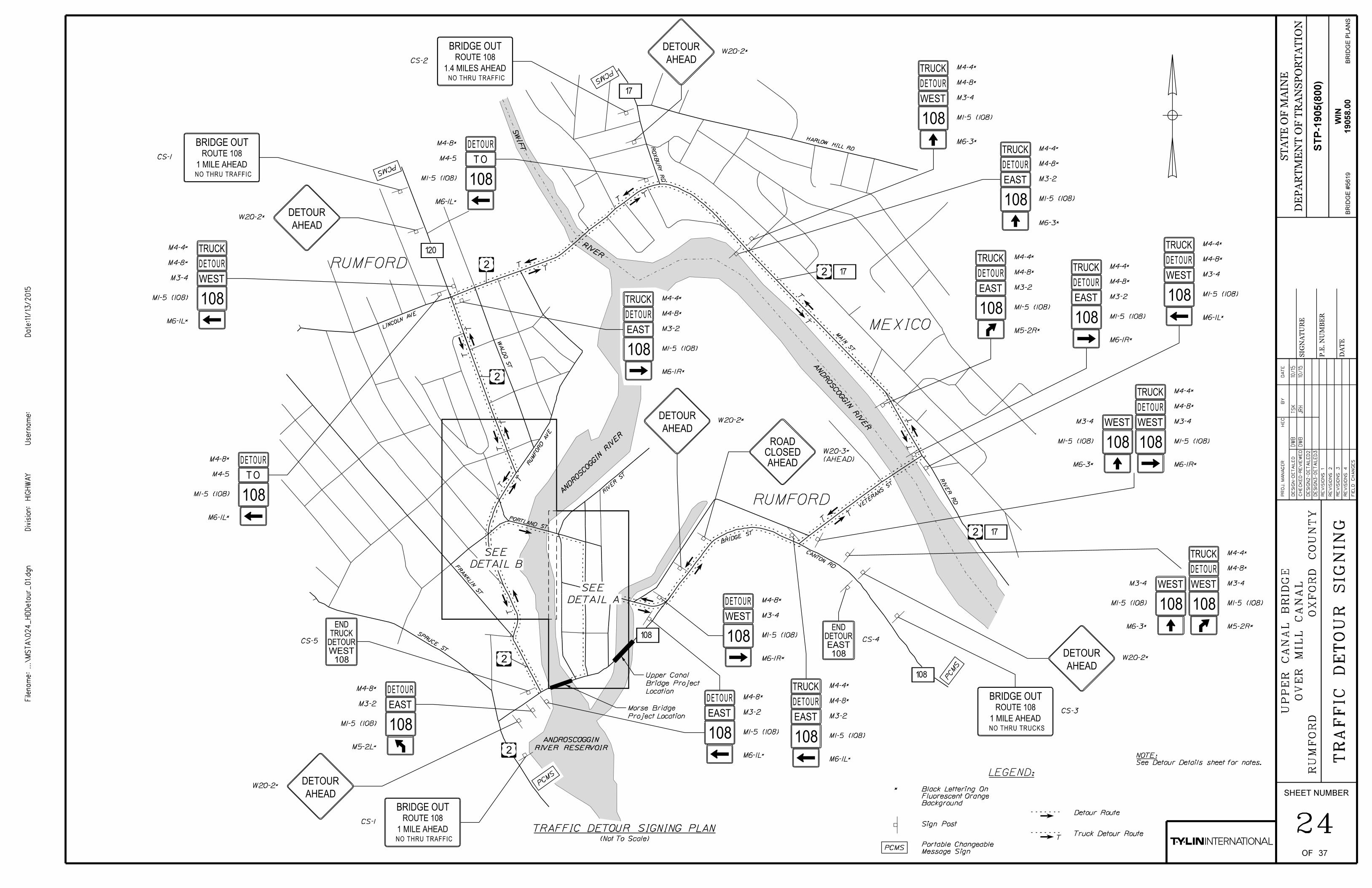
T
LEGEND:
*
PCMS
TRAFFIC DETOUR SIGNING PLAN
DETAIL A
SEE
DETOUR
EAST
TRUCK
108
DETOUR
AHEAD
108
WEST
DETOUR
TRUCK
108
WEST
DETOUR
TRUCK
108
WESTDETOUR
EAST
TRUCK
108
M4-4*
M4-8*
M1-5 (108)
M6-1R*
M1-5 (108)
M4-4*
M4-8*
M1-5 (108)
M6-1L*
M4-4*
M4-8*
M1-5 (108)
M6-1R*
M3-2
M3-4
M3-4M3-4
M6-3*
W20-2*
M4-4*
M4-8*
M1-5 (108)
M6-1L*
M3-2
DETOUR
EAST
108
M4-8*
M1-5 (108)
M6-1L*
M3-2
DETOUR
108
WEST
M4-8*
M1-5 (108)
M6-1R*
M3-4
DETOUR
AHEADW20-2*
PC
MS
PCM
S
DETOUR
TRUCK
108
M4-4*
M4-8*
M1-5 (108)
M6-3*
DETOUR
TRUCK
108
WEST
M4-4*
M4-8*
M1-5 (108)
M3-4
M6-3*
EAST M3-2
PCMS
DETOUR
AHEADW20-2*
DETOUR
EAST
TRUCK
108
M4-4*
M4-8*
M1-5 (108)
M6-1R*
M3-2
WEST
DETOUR
108
AN
DR
OS
CO
GGIN RIV
ER
ANDROSCOGGIN RIV
ER
RIVER RESERVOIR
ANDROSCOGGIN
SWIF
T
RIVE
R
BRIDGE OUT
NO THRU TRAFFIC
ROUTE 108
1 MILE AHEAD
TR
AF
FIC
DE
TO
UR
SIG
NIN
G
BRIDGE OUT
NO THRU TRAFFIC
ROUTE 108
1 MILE AHEAD
Truck Detour Route
Detour Route
Sign Post
Background
Fluorescent Orange
Black Lettering On
Message Sign
Portable Changeable(Not To Scale)
DW
B
DW
B
TS
K
JR
H
10/15
10/15
NOTE:
See Detour Details sheet for notes.
24
DETAIL B
SEE
DETOUR
EAST
108
M4-8*
M1-5 (108)
M3-2
M5-2L*
CS-1
108WESTDETOURTRUCK
END
CS-5
CS-1
DETOUR
AHEAD
AHEAD
CLOSED
ROAD
CS-3
BRIDGE OUT
NO THRU TRUCKS
ROUTE 108
1 MILE AHEAD
108EAST
DETOUREND
108
WEST
DETOUR
TRUCK
108
WEST
M4-8*
M1-5 (108)
M5-2R*
M1-5 (108)
M3-4M3-4
M6-3*
M4-4*
DETOUR
EAST
TRUCK
108
M4-4*
M4-8*
M1-5 (108)
M3-2
M5-2R*
M4-8*
M1-5 (108)
M4-5
M6-1L*
DETOUR
TRUCK
108
M4-8*
M1-5 (108)
M3-4
M6-1L*
M4-4*
TO
(AHEAD)
W20-3*
W20-2*
CS-4
PCMS
CS-2
DETOUR
AHEADW20-2*
DETOUR
108
M4-8*
M1-5 (108)
M4-5
M6-1L*
TO
BRIDGE OUT
NO THRU TRAFFIC
ROUTE 108
1.4 MILES AHEAD
DE
SIG
N-
DE
TAIL
ED
BY
DA
TE
PR
OJ.
MA
NA
GE
R
SHEET NUMBER
FIE
LD
CH
AN
GE
S
RE
VISIO
NS
1
RE
VISIO
NS
2
RE
VISIO
NS
3
RE
VISIO
NS
4
CH
EC
KE
D-
RE
VIE
WE
D
HIG
HW
AY
Divisio
n:
Filena
me:...\
MS
TA\
02
4_
HD
Detour_
01.d
gn
Userna
me:
Date:1
1/13/2
015
OF
DE
SIG
N2-
DE
TAIL
ED
2
DE
SIG
N3-
DE
TAIL
ED
3
BRID
GE P
LA
NS
ST
AT
E O
F M
AIN
E
DE
PA
RT
ME
NT O
F T
RA
NSP
OR
TA
TIO
N
DA
TE
SIG
NA
TU
RE
P.E.
NU
MB
ER
UP
PE
R
CA
NA
L
BRID
GE
OX
FO
RD
CO
UN
TY
WIN
19058.0
0B
RID
GE #
5619
R
UM
FO
RD
37
HE
C
STP-1
905(8
00)
OV
ER
MIL
L
CA
NA
L
T
T
T
TT
TT
T
T
TT
TT
TT
TT
°108
°108
2
22
2
°17
VETE
RANS ST
°17
HARLOW HILL RD
°120
2
2
°17
FR
ANKLIN ST
SPRUCE ST
RU
MF
OR
D
AVE
MEXICO
RUMFORD
WA
LD
O S
T
LINCOL
N AVE
PORTLAND ST
RIV
ER ST
BRIDGE S
T
CANTON RD
RIVE
R
RD
MAIN ST
RO
XB
UR
Y
RD
RIVER RESERVOIR
ANDROSCOGGIN
RIVE
R
AN
DR
OS
CO
GGIN RIV
ER
ANDROSCOGGIN RIV
ER
SWIF
T
RUMFORD
Location
Bridge Project
Upper Canal
Project Location
Morse Bridge

DETOUR
EAST
TRUCK
108
M4-4*
M4-8*
M1-5 (108)
M5-2L*
M3-2
DETOUR
TRUCK
108
WEST
DETOUR
108
DETOUR
TRUCK
108
M4-8*
M1-5 (108)
M6-1R*
M4-8*
M1-5 (108)
M3-2
M6-3*
EAST M3-2EAST
M4-4*
DETOUR
TRUCK
108
WEST
M4-8*
M1-5 (108)
M3-4
M6-3*
M4-4*
M4-8*
M1-5 (108)
M3-4
M5-2R*
M4-4*
DETOUR
108
DETOUR
TRUCK
108
M4-8*
M1-5 (108)
M5-2R*
M4-8*
M1-5 (108)
M3-2
M6-3*
EAST M3-2EAST
M4-4*
DETOUR
108
M4-8*
M1-5 (108)
M6-1L*
EASTM3-2
PORTLAND ST
CO
NG
RE
SS
ST
RIV
ER
ST
CA
NA
L S
T
108°
RIV
ER ST
DEPT
FIRE
RUMFORD
T
T
T
TT
FR
ANKLIN ST
RU
MF
OR
D
AVE
PORTLAND ST
LEGEND:
*
M4-8*
M1-5 (108)
M6-1L*
M3-4
M4-8*
M1-5 (108)
M6-3*
M3-2
DETAIL A
M4-8*
M1-5 (108)
M3-2
M6-1R*
M4-8*
M1-5 (108)
M3-2
M6-1L*
(DRIVEWAY)
R10-7
R1-1
M4-8*
M1-5 (108)
M3-4
M6-3*
M1-5 (108)
M6-1R*
M3-4
M4-8*
DE
TO
UR
DE
TAIL
S
DETAIL C
DETOUR
108
WEST
DETOUR
108
EAST
DETOUR
EAST
108
DETOUR
EAST
108
STOP
DO NOT
BLOCKDRIVEWAY
DETOUR
108
WEST
108
WEST
DETOUR
DO NOT
BLOCKDRIVEWAY
DETOUR SIGNING NOTES
See Detail C
LO
WE
LL S
TR
EE
T
(Not To Scale)
Project Location
Upper Canal Bridge
Project BH-2261(400)X
Morse Bridge
Portland Street
Savings Bank
Franklin
Riv
er Str
eet
Dunkin Donuts
Lo
well Str
eet
Congress Str
eet
Maine District Court
Davis Florist
(Not to Scale)
Fire Department
Town of Rumford
(Driveway)
R10-7
Sign Post
Detour Route
Background
Fluorescent Orange
Black Lettering On
DW
BT
SK
10/15
DW
BJ
RH
10/15
additional information and requirements.
west of this Project. See project-specific Special Provisions for
painting project on Morse Bridge, located approximately 500 ft
This detour shall remain in place for the duration of a concurrent
the 652 Items.
detour is disassembled. Payment for this work will be incidental to
removed or covered shall be replaced or uncovered when the
detour shall be removed or covered by the Contractor. All signs
Existing signs that are in conflict with the traffic flow of the
possible.
maintain at least 200 feet between sign assemblies whenever
existing sign assemblies when possible. The Contractor shall
control sign assemblies and shall modify or be placed adjacent to
Installation of detour signs shall not block any existing traffic
Item 652.41, "Portable-Changeable Message Sign."
signs, including relocating during construction, shall be included in
once construction has begun if necessary. Payment for these
These shall then be deployed to locations specified by the Resident
prior to the start of construction to warn of impending detours.
designated on the Plans or as directed by the Resident 14 days
Portable Changeable Message Signs "PCMS" shall be placed where
Transportation Standard Details.
Standard Highway Signs (SHS) book, and the Maine Department of
of the Manual on Uniform Traffic Control Devices (MUTCD), the
and the Resident. Signs shall be in accordance with latest edition
Exact sign locations will be coordinated between the Contractor
5.
4.
3.
2.
1.
M4-8*
M1-5 (108)
M3-2
M5-2L*
DETOUR
EAST
108
Pavement Tape, Item 627.51)
(to be applied using 6" Temporary
and Diagonal Lines
6" Solid White Outline Box
CS-6
DETAIL B(Not To Scale)
AN
DR
OS
CO
GGIN
RIV
ER
MILL C
AN
AL
AN
DR
OS
CO
GGIN
RIV
ER
DETOUR
AHEADW20-2*
DETOUR
EAST
TRUCK
108
M4-4*
M4-8*
M1-5 (108)
M6-1R*
M3-2
25
DETOUR
AHEADW20-2*
108WESTDETOUR
END
DE
SIG
N-
DE
TAIL
ED
BY
DA
TE
PR
OJ.
MA
NA
GE
R
SHEET NUMBER
FIE
LD
CH
AN
GE
S
RE
VISIO
NS
1
RE
VISIO
NS
2
RE
VISIO
NS
3
RE
VISIO
NS
4
CH
EC
KE
D-
RE
VIE
WE
D
HIG
HW
AY
Divisio
n:
Filena
me:...\
MS
TA\
02
5_
HD
Detour_
02.d
gn
Userna
me:
Date:1
1/13/2
015
OF
DE
SIG
N2-
DE
TAIL
ED
2
DE
SIG
N3-
DE
TAIL
ED
3
BRID
GE P
LA
NS
ST
AT
E O
F M
AIN
E
DE
PA
RT
ME
NT O
F T
RA
NSP
OR
TA
TIO
N
DA
TE
SIG
NA
TU
RE
P.E.
NU
MB
ER
UP
PE
R
CA
NA
L
BRID
GE
OX
FO
RD
CO
UN
TY
WIN
19058.0
0B
RID
GE #
5619
R
UM
FO
RD
37
HE
C
STP-1
905(8
00)
OV
ER
MIL
L
CA
NA
L

T
T
AHEAD
WORK
ROAD
AHEAD
ROAD
ONE LANE
CLOSED
ROAD
200 FT
CLOSED
ROAD
CLOSED
ROAD
2
°108
2
Riv
er Str
eet
Congress Street
Canal Street
*
Bridge Street
DETOUREND
(200 FT)
W20-3*
W20-4*
M4-8a*
(AHEAD)
W20-1*
OR
Match
Existi
ng Tap
er
Interval On Tangent
Drums Spaced @ 40'
Interval On Taper
Drums Spaced @ 40'
Project Location
Upper Canal Bridge
X X X X X X X X X X X
X X X X X X X X X X X X X
X X X X X X
CLOSED
ROAD
Conflict With New Pavement Markings (Typ)
Remove Existing Pavement Markings That
X X X X
CO
NS
TR
UC
TIO
N
SIG
NIN
G
PLANNot To Scale
200'
Temporary Concrete Barrier
Drum
Type III Barricade
Sign Post
Line
Temporary Single White Edge TSWEL
LEGEND:
Background
Fluorescent Orange
Black Lettering On
Existing Pavement Striping
Pavement Marking
Remove Existing
Detour Route
Truck Detour Route
New Detour Road
Mill
Canal
500 FT
CLOSED
ROAD
(500 FT)
W20-3*
Entrance
Gravel
TS
WE
L
Androscoggin
Riv
er
Project BH-2261(400)X
Morse Bridge
Existing Traffic Signals
Entrance
Paved
500 FT
CLOSED
ROAD
(500 FT)
W20-3*
DO NOT
ENTER
ONLY
STOP
R3-5
R1-1
R5-1
Close Entrance
DW
B
DW
B
TS
K
JR
H
10/15
10/15
(By Others)
Drums
26
DETOUR
M4-10L*
R11-2
DETOUR
M4-10L*
R11-2
M4-10R*
R11-2
DETOUR
See Detour Details sheet for additional notes.
for the duration of the detour.
Congress Street shall be adjusted to flashing yellow
Traffic signal at the intersection of Bridge Street and
2.
1.
NOTES:
DE
SIG
N-
DE
TAIL
ED
BY
DA
TE
PR
OJ.
MA
NA
GE
R
SHEET NUMBER
FIE
LD
CH
AN
GE
S
RE
VISIO
NS
1
RE
VISIO
NS
2
RE
VISIO
NS
3
RE
VISIO
NS
4
CH
EC
KE
D-
RE
VIE
WE
D
HIG
HW
AY
Divisio
n:
Filena
me:...\
MS
TA\
02
6_
HD
Detour_
03.d
gn
Userna
me:
Date:1
1/13/2
015
OF
DE
SIG
N2-
DE
TAIL
ED
2
DE
SIG
N3-
DE
TAIL
ED
3
BRID
GE P
LA
NS
ST
AT
E O
F M
AIN
E
DE
PA
RT
ME
NT O
F T
RA
NSP
OR
TA
TIO
N
DA
TE
SIG
NA
TU
RE
P.E.
NU
MB
ER
UP
PE
R
CA
NA
L
BRID
GE
OX
FO
RD
CO
UN
TY
WIN
19058.0
0B
RID
GE #
5619
R
UM
FO
RD
37
HE
C
STP-1
905(8
00)
OV
ER
MIL
L
CA
NA
L
300'

WEST
DETOUR
TRUCK
TO
DO NOT
BLOCKDRIVEWAY
DETOUR
DETOUR
EASTM3-2 24" 12" BLACK
WHITE BLACK24"
WHITE
REQUIRED
SIGNS
OF
NUMBER
SIGN
SIZE OF
WIDTH HEIGHT
TEXT
TEXT DIMENSIONS (INCHES)
HEIGHT
LETTER
SPACING
VERTICAL
RTE. MKR.
ARROW
REQUIRED
SIGNS
OF
NUMBER
GROUND
BACK-
COLOR
BORDER
LEGENDRADIUS
BORDER
FEET
SQUARE
AREA INNOTES
NUMBER
CATION
IDENTIFI-
REQUIRED
SIGNS
OF
NUMBER
SIGN
SIZE OF
WIDTH HEIGHT
TEXT
TEXT DIMENSIONS (INCHES)
HEIGHT
LETTER
SPACING
VERTICAL
RTE. MKR.
ARROW
REQUIRED
SIGNS
OF
NUMBER
GROUND
BACK-
COLOR
BORDER
LEGENDRADIUS
BORDER
FEET
SQUARE
AREA INNOTES
NUMBER
CATION
IDENTIFI-
HIGHWAY SIGNS" - 2009
CONFORM TO "STANDARD
TEXT DIMENSIONS SHALL
108(108)
M1-5 30" 36
24" 12" BLACKWHITEM3-4 13
24" 12" BLACKM4-4 16
24" 12" BLACKM4-8 34
ORANGE
ORANGE
24" 18"M4-8A BLACK
BLACK21" 15"
BLACK21" 15"
BLACKM6-3 15"21"
4
ORANGE
ORANGE
ORANGE
ORANGE
11
9
R1-1 30" 30" 3 RED WHITE
(180)
5.00
(42)
2.00
(26)
2.00
(32)
2.00
(68)
2.00
(3)
3.00
(8.8)
2.19
(24.1)
2.19
(19.7)
2.19
STOP
24" 30" 2 BLACK
(10)
5.00WHITER10-7
(DRIVEWAY)
36" 36" ORANGE
BLACK
1
(9)
9.00
36" 36"W20-2
AHEAD
DETOURORANGE
BLACK
7
(63)
9.00
36" 36" ORANGE
BLACK
36" 36" ORANGE
BLACK
1
(9)
9.00
(AHEAD)
W20-1
AHEAD
WORK
ROAD
___ FT
CLOSED
ROAD
AHEAD
ROAD
ONE LANEW20-4
30" BLACKR11-2 48" WHITE3
CLOSED
ROAD
(30)
10.00
TR
AF
FIC
SIG
N
SU
MM
AR
Y
21
(18.75)
6.25
R3-5 30" 36" 1 BLACK
R5-1 30" 30" RED WHITE
WHITE
(7.5)
7.50
2
(12.5)
6.25
2
1
(500 ft)
(200 ft)
W20-3
(18)
9.00
(9)
9.00
DW
B
DW
B
TS
K
JR
H
10/15
10/15
27
60"
4" 4" 4"
5C
5C
NO THRU TRAFFIC
1 MILE AHEAD
ROUTE 108
BRIDGE OUT
CS-1
6C
4C
40" 2 BLACKORANGE
24" 12"M4-5 2 WHITE
(4)
2.00BLACK
1
BLACKORANGE2M4-10L 48" 18"
BLACKORANGE1M4-10R 48" 18"
(12)
6.00
(6)
6.00
M5-2L
BLACK21" 15" 4 ORANGE
(8.8)
2.19M5-2R
BLACK21" 15" ORANGE8
(17.5)
2.19
M6-1L
M6-1R
(33.3)
16.67
ONLY
DO NOT
ENTER
36" 36" ORANGE
BLACK
1
(9)
9.00(AHEAD)
W20-3
AHEAD
CLOSED
ROAD
2 ORANGE
BLACK
(10)
5.00W1-8R 24" 30"
60"
4" 4" 4"
5C
5C
CS-2
6C
4C
40" 1 BLACKORANGE
60"
4" 4" 4"
5C
5C
CS-3
6C
4C
40" 1 BLACKORANGE
(16.7)
16.67
(16.7)
16.67
NO THRU TRAFFIC
1.4 MILE AHEAD
ROUTE 108
BRIDGE OUT
NO THRU TRUCKS
1 MILE AHEAD
ROUTE 108
BRIDGE OUT
DETOUREND
24" BLACKORANGE1
108EAST
DETOUREND
24" BLACKORANGE1
108WESTDETOURTRUCK
END
CS-4
CS-5
CS-6 24" BLACKORANGE1
108WESTDETOUR
END
32"
39"
32"
(5.3)
5.33
(5.3)
5.33
(6.5)
6.5
4D
4D
4D
4D
3"
3"
3"
4D
4D
4D
4D
3"
3"
3"
4D
4D3"
4D
4D
4D
3"
3"
3"
HIGHWAY SIGNS" - 2009
CONFORM TO "STANDARD
TEXT DIMENSIONS SHALL
DE
SIG
N-
DE
TAIL
ED
BY
DA
TE
PR
OJ.
MA
NA
GE
R
SHEET NUMBER
FIE
LD
CH
AN
GE
S
RE
VISIO
NS
1
RE
VISIO
NS
2
RE
VISIO
NS
3
RE
VISIO
NS
4
CH
EC
KE
D-
RE
VIE
WE
D
HIG
HW
AY
Divisio
n:
Filena
me:...\
MS
TA\
02
7_
Sig
nS
um
_01.d
gn
Userna
me:
Date:1
1/13/2
015
OF
DE
SIG
N2-
DE
TAIL
ED
2
DE
SIG
N3-
DE
TAIL
ED
3
BRID
GE P
LA
NS
ST
AT
E O
F M
AIN
E
DE
PA
RT
ME
NT O
F T
RA
NSP
OR
TA
TIO
N
DA
TE
SIG
NA
TU
RE
P.E.
NU
MB
ER
UP
PE
R
CA
NA
L
BRID
GE
OX
FO
RD
CO
UN
TY
WIN
19058.0
0B
RID
GE #
5619
R
UM
FO
RD
37
HE
C
STP-1
905(8
00)
OV
ER
MIL
L
CA
NA
L

DE
SIG
N-
DE
TAIL
ED
BY
DA
TE
PR
OJ.
MA
NA
GE
R
SHEET NUMBER
FIE
LD
CH
AN
GE
S
RE
VISIO
NS
1
RE
VISIO
NS
2
RE
VISIO
NS
3
RE
VISIO
NS
4
CH
EC
KE
D-
RE
VIE
WE
D
HIG
HW
AY
Divisio
n:
Filena
me:...\
TR
AF
FIC\
MS
TA\
02
8_
BD
Detour1.d
gn
Userna
me:
Date:1
1/13/2
015
OF
DE
SIG
N2-
DE
TAIL
ED
2
DE
SIG
N3-
DE
TAIL
ED
3
WIN
BRID
GE P
LA
NS
ST
AT
E O
F M
AIN
E
DE
PA
RT
ME
NT O
F T
RA
NSP
OR
TA
TIO
N
DA
TE
SIG
NA
TU
RE
P.E.
NU
MB
ER
19058.0
0
19058.0
0
UP
PE
R
CA
NA
L
BRID
GE
MIL
L
CA
NA
L (A
ND
RO
SC
OG
GIN
RIV
ER)
RU
MF
OR
DO
XF
OR
D
CO
UN
TY
BRID
GE N
O. 5619
R.
MY
ER
SM
RP
28
DE
TO
UR
PL
AN
37
M.
WIG
HT
Scale of Feet
DETOUR PLAN
25 0 25 50
24" x 30"
W1-8R
24" x 30"
W1-8R
33+
49.0
3
PC
=
ST
A.
IPF
IPF
505
505
510
510
515
515
515
515
515
520
520
520
525
525
530
JOINT CMP 2 BELL 2
15" C
MP
-30
24" C
MP
3X5
X3
FAIR
.3
X3
X2
PLUNGE POOL
BO
TT
EM
OF
BA
NK
FAIR
24" C
MP
.
3X3X2
AB
AN
DO
NED
1" DIA IRON PIPE
SIN
KH
OLE
PA
VE
D
.
2X2X2
DAN
GER IN
FO
1" DIA IRON PIPE
15" PVC
TO
P
OF
BA
NK
CONC ROAD
SPEED LIMIT 25
.
2X2X2
12 FT
NO JAKE BRAKE
6' T
ALL
HA
RTF
OR
D
BRID
GE
STOP LIGHT
.
GR
ANIT
E
PAVED
STONE 3FT WIDE
CMP J1 NETT 6
JOINT
PA
VE
D
CANAL BR
NETT 7 JOINT
RUMFORD INFO SIGN
WO
OD
S
EN
TR
AN
CE
BUSINESS DISTRICT
LIMIT 45
SPEED
NETT 900/5CMP 16S J16
NETT 900/5CMP J16
COVERCONC
NETT 6CMP 1S
J1
Min.
12' Crash
CushionWork Z
one
41+
00
42
+00
43+0044+00
PC = STA. 41+
91.07
PC = STA. 40+00.00
PT = STA. 40+86.22
40+
00
PC
C
=
ST
A.
42
+93.0
8
PT
=
ST
A.
44
+06.4
4
33+
00
34+00
35+00
36+00
PC
=
ST
A.
35
+01.1
3
PT
=
ST
A.
35
+23.8
8
PO
E
=
ST
A.
36
+21.8
5
E = 7.91'
T = 35.35'
L = 66.06'
R = 75.00'
PI = 33+84.38
CURVE DATA #2
PT =
ST
A. 34+
15.1
0
E = 0.06'
T = 11.38'
L = 22.75'
R = 1000.00'
PI = 35+12.50
CURVE DATA #3
8+00
9+00
10+00
11+00
11+60
PT
=
ST
A.
8+
86.5
3
PO
E
=
ST
A.
11
+60.0
1

DE
SIG
N-
DE
TAIL
ED
BY
DA
TE
PR
OJ.
MA
NA
GE
R
SHEET NUMBER
FIE
LD
CH
AN
GE
S
RE
VISIO
NS
1
RE
VISIO
NS
2
RE
VISIO
NS
3
RE
VISIO
NS
4
CH
EC
KE
D-
RE
VIE
WE
D
HIG
HW
AY
Divisio
n:
Filena
me:...\
TR
AF
FIC\
MS
TA\
02
9_
BD
Detour2.d
gn
Userna
me:
Date:1
1/13/2
015
OF
DE
SIG
N2-
DE
TAIL
ED
2
DE
SIG
N3-
DE
TAIL
ED
3
WIN
BRID
GE P
LA
NS
ST
AT
E O
F M
AIN
E
DE
PA
RT
ME
NT O
F T
RA
NSP
OR
TA
TIO
N
DA
TE
SIG
NA
TU
RE
P.E.
NU
MB
ER
19058.0
0
19058.0
0
UP
PE
R
CA
NA
L
BRID
GE
MIL
L
CA
NA
L (A
ND
RO
SC
OG
GIN
RIV
ER)
RU
MF
OR
DO
XF
OR
D
CO
UN
TY
BRID
GE N
O. 5619
R.
MY
ER
SM
RP
29
DE
TO
UR
LA
YO
UT
M.
WIG
HT
Oct.
2015
37
MC10
MC11
CONTROL POINTS FOR MC10
10
9
8
7
6
5
4
3
2
1
1
2
3
4
5
6
7
8
9
10
940346.185
940299.487
940285.552
940276.366
940268.486
940258.870
940248.309
940225.042
940208.205
940205.871
624000.571
624051.466
624080.475
624105.607
624129.333
624152.482
624175.317
624209.372
624226.961
624233.288
Point Station Offset X Coord. Y Coord.
42+64.17
42+25.00
42+00.00
41+75.00
41+50.00
41+25.00
41+00.00
40+50.00
40+18.28
40+12.52
52.53'
19.50'
12.00'
12.00'
12.00'
13.83'
16.65'
22.40'
18.21'
13.37'
Point Station Offset X Coord. Y Coord.
CONTROL POINTS FOR MC11
940425.097
940411.307
940402.138
940366.760
940307.687
940302.002
940274.129
940294.317
940282.991
9
8
7
6
5
4
3
2
1
624113.007
624098.552
624091.699
624139.158
624135.377
624224.198
624214.913
624240.684
624251.496
1
2-PC
3-CC
4-PT
5-PC
6-CC
98
7-PT
R = 25'
R =
59'
43+67.39
43+46.07
43+33.79
43+32.95
41+56.62
40+76.37
40+73.68
40+65.04
40+55.36
15.89'
14.35'
14.56'
73.75'
27.11'
50.62'
21.49'
51.84'
49.00'
1
2
3
1
2
3
Deto
ur Road
Route 108
Railroad Street
Hartf
ord Street
8+00
9+00
10+00
11+00
33+
00
34+00
35+00
36+00
Sta. 44+06.44 Detour Road
Sta. 10+65.00 Route 108 =
Sta. 40+00.00 Detour Road
Sta. 30+49.03 Hartford Street =
PC = STA. 40+00.00
PT = STA. 40+86.22
PC = STA. 41+
91.07 PC
C
=
ST
A.
42
+93.0
8
PT
=
ST
A.
44
+06.4
4
41+
00
40+
00
42
+00
43+0044+00
33+
00
34+00
35+00
36+00
8+00
9+00
10+00
11+00
11+60
E = 7.33'
T = 57.91'
L = 113.37'
R = 225.00'
PI = 43+50.99
CURVE DATA #3
DETOUR ROAD
E = 12.24'
T = 47.23'
L = 86.22'
R = 85.00'
PI = 40+47.23
CURVE DATA #1
DETOUR ROAD
E = 30.92'
T = 68.31'
L = 102.01'
R = 60.00'
PI = 42+59.38
CURVE DATA #2
DETOUR ROAD

Scale of Feet
25 0 25 50
5 0 5 10
PROFILE
Horiz.
Vert.
500
505
510
515
520
525
530
535
540
545545
500
505
510
515
520
525
530
535
540
545545
G1 = 2.05% G2 = 9.04%
E = 1.311'
SD = 138'
PV
C =
ST
A. 40+5
0
PVT =
ST
A. 43
+00
ELE
V. =
525.5
0
PVI =
ST
A. 42
+50
V.C.L. = 100'V.C.L. = 150'
G2 = 6.20%G1 = 9.04%
E = -0.355'
SD = 430'
ELE
V. =
514.2
0
PVI =
ST
A. 41+25
EL. 512.6
3
EL. 512.5
2
EL. 512.6
6
EL. 513.3
2
EL. 514.2
7
EL. 515.5
1
EL. 517.0
4
EL. 518.8
7
EL. 520.9
8
EL. 523.15
EL. 525.15
EL. 526.9
6
EL. 528.6
0
EL. 530.16
EL. 512.6
3
EL. 512.5
3
EL. 512.5
8
EL. 513.2
7
EL. 513.7
6
EL. 513.9
8
EL. 514.1
2
EL. 514.4
0
EL. 514.8
3
EL. 515.3
9
EL. 515.8
9
EL. 522.7
6
EL. 528.0
4
EL. 530.1
0
EL. 531.6
7
EL. 533.0
4
EL. 534.2
1
É Route 10
8
ST
A. 43
+13.0
ELE
V. =
529.4
±
Edge of Pave
ment -
Route 10
8
Edge of Travel Lane -
Route 10
8
PROFILE
40+00 41+00 42+00 43+00 44+00 45+00
40+00 41+00 42+00 43+00 44+00 45+00
ST
A. 40+3
9.9
± E
LE
V. =
512.5
±
PV
CC =
ST
A. 42
+00
ST
A. 43
+37.3
±
ELE
V. 530.9
±
Centerline of Hartf
ord Street
Edge of Pave
ment -
Hartf
ord Street
Proposed Grade
Existing Ground
Detour
Match Existing
DE
SIG
N-
DE
TAIL
ED
BY
DA
TE
PR
OJ.
MA
NA
GE
R
SHEET NUMBER
FIE
LD
CH
AN
GE
S
RE
VISIO
NS
1
RE
VISIO
NS
2
RE
VISIO
NS
3
RE
VISIO
NS
4
CH
EC
KE
D-
RE
VIE
WE
D
HIG
HW
AY
Divisio
n:
Filena
me:...\
MS
TA\
03
0_
Profile_
Detour.d
gn
Userna
me:
Date:1
1/13/2
015
OF
DE
SIG
N2-
DE
TAIL
ED
2
DE
SIG
N3-
DE
TAIL
ED
3
BRID
GE P
LA
NS
ST
AT
E O
F M
AIN
E
DE
PA
RT
ME
NT O
F T
RA
NSP
OR
TA
TIO
N
DA
TE
SIG
NA
TU
RE
P.E.
NU
MB
ER
19058.0
0
19058.0
0
UP
PE
R
CA
NA
L
BRID
GE
MIL
L
CA
NA
L (A
ND
RO
SC
OG
GIN
RIV
ER)
RU
MF
OR
DO
XF
OR
D
CO
UN
TY
BRID
GE N
O. 5619
R.
MY
ER
SM
RP
S.
BO
DG
E
PR
OFIL
E -
DE
TO
UR
WIN
37
30

15" CMP
15" CMP
15" CMP
HIG
HW
AY
Divisio
n:
Filena
me:...\
MS
TA\
03
1_
Xsect_
Detour.d
gn
Userna
me:
Date:1
1/13/2
015
DE
SIG
N-
DE
TAIL
ED
BY
DA
TE
PR
OJ.
MA
NA
GE
R
SHEET NUMBER
FIE
LD
CH
AN
GE
S
RE
VISIO
NS
1
RE
VISIO
NS
2
RE
VISIO
NS
3
RE
VISIO
NS
4
CH
EC
KE
D-
RE
VIE
WE
D
OF
DE
SIG
N2-
DE
TAIL
ED
2
DE
SIG
N3-
DE
TAIL
ED
3
BRID
GE P
LA
NS
DE
PA
RT
ME
NT O
F T
RA
NSP
OR
TA
TIO
N
ST
AT
E O
F M
AIN
E
DA
TE
SIG
NA
TU
RE
P.E.
NU
MB
ER
500
505
510
515
520
0 5 10 15 20 25 30 35 40 45 50 55 60 65 70-5-10-15-20-25-30-35-40-45-50-55-60-65-70
500
505
510
515
520
0 5 10 15 20 25 30 35 40 45 50 55 60 65 70-5-10-15-20-25-30-35-40-45-50-55-60-65-70
505
510
515
520
0 5 10 15 20 25 30 35 40 45 50 55 60 65 70-5-10-15-20-25-30-35-40-45-50-55-60-65-70
505
510
515
520
0 5 10 15 20 25 30 35 40 45 50 55 60 65 70-5-10-15-20-25-30-35-40-45-50-55-60-65-70
505
510
515
520
0 5 10 15 20 25 30 35 40 45 50 55 60 65 70-5-10-15-20-25-30-35-40-45-50-55-60-65-70
505
510
515
520
0 5 10 15 20 25 30 35 40 45 50 55 60 65 70-5-10-15-20-25-30-35-40-45-50-55-60-65-70
505
510
515
520
0 5 10 15 20 25 30 35 40 45 50 55 60 65 70-5-10-15-20-25-30-35-40-45-50-55-60-65-70
505
510
515
520
0 5 10 15 20 25 30 35 40 45 50 55 60 65 70-5-10-15-20-25-30-35-40-45-50-55-60-65-70
CL
CL
CL
CL
CL
CL
512.66
513.32
CLCLCLCLCL
1.9% 2.7% 0.9%512.63
512.52
INV. ELEV. 508.03
INV. ELEV. 507.21
INV. ELEV. 507.08
49.0' RT.
STA. 0+35.09
INV. ELEV. 505.51
CURB
CURB
CURB
STONE WALL
-0.4%
HARTFORD STREET
HARTFORD STREET PAVED
APRON
HARTFORD STREET GRAVEL ENTRANCE PAVED APRON
PAVED APRONGRAVEL ENTRANCE
& PARKING AREA
LINE
TREE
LINE
TREE
LINE
TREE
0.1%
2.8%
PR
OJE
CT N
O. 019058.0
0
WIN
19058.0
0
MR
PR.
MY
ER
S
ST
EV
E
BO
DG
E
UP
PE
R
CA
NA
L
BRID
GE
MIL
L
CA
NA
L (A
ND
RO
SC
OG
GIN
RIV
ER)
RU
MF
OR
DO
XF
OR
D
CO
UN
TY
BRID
GE N
O. 5619
40+00.00
40+25.00
40+50.00
40+75.00
Sta. 40+00.00 to Sta. 40+75.00
-0.7%
-0.5%
3137
CR
OS
S
SE
CTIO
NS -
DE
TO
UR
RO
AD
ELEV. 512.24
13.28' LT.
STA. 0+00.0
CATCH BASIN
ELEV. 512.32
12.83' RT.
STA. 0+01.85
CATCH BASIN
25.56' LT.
STA. 0+17.09
FIRE HYDRANT
FENCE
FENCE
GUARDRAIL
GUARDRAIL GUARDRAIL
GUARDRAIL
GUARDRAIL
28.87' RT.
STA. 0+60.57
POLE (ABANDONED)
EP
EP
ELEV. UNKNOWN
19.4' LT.
12" WATER
ELEV. UNKNOWN
25.0' LT.
12" WATER
ELEV. UNKNOWN
46.4' LT.
12" WATER

HIG
HW
AY
Divisio
n:
Filena
me:...\
MS
TA\
03
1_
Xsect_
Detour.d
gn
Userna
me:
Date:1
1/13/2
015
DE
SIG
N-
DE
TAIL
ED
BY
DA
TE
PR
OJ.
MA
NA
GE
R
SHEET NUMBER
FIE
LD
CH
AN
GE
S
RE
VISIO
NS
1
RE
VISIO
NS
2
RE
VISIO
NS
3
RE
VISIO
NS
4
CH
EC
KE
D-
RE
VIE
WE
D
OF
DE
SIG
N2-
DE
TAIL
ED
2
DE
SIG
N3-
DE
TAIL
ED
3
BRID
GE P
LA
NS
DE
PA
RT
ME
NT O
F T
RA
NSP
OR
TA
TIO
N
ST
AT
E O
F M
AIN
E
DA
TE
SIG
NA
TU
RE
P.E.
NU
MB
ER
505
510
515
520
525
0 5 10 15 20 25 30 35 40 45 50 55 60 65 70-5-10-15-20-25-30-35-40-45-50-55-60-65-70
505
510
515
520
525
0 5 10 15 20 25 30 35 40 45 50 55 60 65 70-5-10-15-20-25-30-35-40-45-50-55-60-65-70
505
510
515
520
525
0 5 10 15 20 25 30 35 40 45 50 55 60 65 70-5-10-15-20-25-30-35-40-45-50-55-60-65-70
505
510
515
520
525
0 5 10 15 20 25 30 35 40 45 50 55 60 65 70-5-10-15-20-25-30-35-40-45-50-55-60-65-70
505
510
515
520
525
0 5 10 15 20 25 30 35 40 45 50 55 60 65 70-5-10-15-20-25-30-35-40-45-50-55-60-65-70
505
510
515
520
525
0 5 10 15 20 25 30 35 40 45 50 55 60 65 70-5-10-15-20-25-30-35-40-45-50-55-60-65-70
CL
CL
CL
514.27
515.51
517.04
-2.0%
-2.7%
-2.0% -2.0%
3:1
-2.0%
GRAVEL ENTRANCE & PARKING AREA
GRAVEL ENTRANCE
& PARKING AREA
GRAVEL ENTRANCE
& PARKING AREA
LINE
TREE
LINE
TREE
LINE
TREE
1.2%
PR
OJE
CT N
O. 019058.0
0
WIN
19058.0
0B
RID
GE N
O. 5619
MR
PR.
MY
ER
S
ST
EV
E
BO
DG
E
UP
PE
R
CA
NA
L
BRID
GE
MIL
L
CA
NA
L (A
ND
RO
SC
OG
GIN
RIV
ER)
OX
FO
RD
CO
UN
TY
RU
MF
OR
D
2:1
2:1
2:1
41+00.00
41+25.00
41+50.00
Sta. 41+00.00 to Sta. 41+50.00
3:1-1.2%
37
32
CR
OS
S
SE
CTIO
NS -
DE
TO
UR
RO
AD

HIG
HW
AY
Divisio
n:
Filena
me:...\
MS
TA\
03
1_
Xsect_
Detour.d
gn
Userna
me:
Date:1
1/13/2
015
DE
SIG
N-
DE
TAIL
ED
BY
DA
TE
PR
OJ.
MA
NA
GE
R
SHEET NUMBER
FIE
LD
CH
AN
GE
S
RE
VISIO
NS
1
RE
VISIO
NS
2
RE
VISIO
NS
3
RE
VISIO
NS
4
CH
EC
KE
D-
RE
VIE
WE
D
OF
DE
SIG
N2-
DE
TAIL
ED
2
DE
SIG
N3-
DE
TAIL
ED
3
BRID
GE P
LA
NS
DE
PA
RT
ME
NT O
F T
RA
NSP
OR
TA
TIO
N
ST
AT
E O
F M
AIN
E
DA
TE
SIG
NA
TU
RE
P.E.
NU
MB
ER
505
510
515
520
525
0 5 10 15 20 25 30 35 40 45 50 55 60 65 70-5-10-15-20-25-30-35-40-45-50-55-60-65-70
505
510
515
520
525
0 5 10 15 20 25 30 35 40 45 50 55 60 65 70-5-10-15-20-25-30-35-40-45-50-55-60-65-70
505
510
515
520
525
530
0 5 10 15 20 25 30 35 40 45 50 55 60 65 70-5-10-15-20-25-30-35-40-45-50-55-60-65-70
505
510
515
520
525
530
0 5 10 15 20 25 30 35 40 45 50 55 60 65 70-5-10-15-20-25-30-35-40-45-50-55-60-65-70
505
510
515
520
525
530
0 5 10 15 20 25 30 35 40 45 50 55 60 65 70-5-10-15-20-25-30-35-40-45-50-55-60-65-70
505
510
515
520
525
530
0 5 10 15 20 25 30 35 40 45 50 55 60 65 70-5-10-15-20-25-30-35-40-45-50-55-60-65-70
CL
CL
CL
518.87
520.98
523.15
-2.0%-2.0%
-2.0%
-2.0%
-2.0%
3:1
3:1 2:1
2:1
3:1
WOOD
ENTRANCE
GRAVEL ENTRANCE
& PARKING AREA
WOOD
ENT
GRAVEL ENTRANCE
& PARKING AREA
LINE
TREE
LINE
TREE
LINE
TREE
PR
OJE
CT N
O. 019058.0
0
WIN
19058.0
0B
RID
GE N
O. 5619
MR
PR.
MY
ER
S
ST
EV
E
BO
DG
E
UP
PE
R
CA
NA
L
BRID
GE
MIL
L
CA
NA
L (A
ND
RO
SC
OG
GIN
RIV
ER)
OX
FO
RD
CO
UN
TY
RU
MF
OR
D
2:1
41+75.00
42+00.00
42+25.00
Sta. 41+75.00 to Sta. 42+25.00
-1.0%
3337
CR
OS
S
SE
CTIO
NS -
DE
TO
UR
RO
AD

HIG
HW
AY
Divisio
n:
Filena
me:...\
MS
TA\
03
1_
Xsect_
Detour.d
gn
Userna
me:
Date:1
1/13/2
015
DE
SIG
N-
DE
TAIL
ED
BY
DA
TE
PR
OJ.
MA
NA
GE
R
SHEET NUMBER
FIE
LD
CH
AN
GE
S
RE
VISIO
NS
1
RE
VISIO
NS
2
RE
VISIO
NS
3
RE
VISIO
NS
4
CH
EC
KE
D-
RE
VIE
WE
D
OF
DE
SIG
N2-
DE
TAIL
ED
2
DE
SIG
N3-
DE
TAIL
ED
3
BRID
GE P
LA
NS
DE
PA
RT
ME
NT O
F T
RA
NSP
OR
TA
TIO
N
ST
AT
E O
F M
AIN
E
DA
TE
SIG
NA
TU
RE
P.E.
NU
MB
ER
505
510
515
520
525
530
535
0 5 10 15 20 25 30 35 40 45 50 55 60 65 70-5-10-15-20-25-30-35-40-45-50-55-60-65-70
505
510
515
520
525
530
535
0 5 10 15 20 25 30 35 40 45 50 55 60 65 70-5-10-15-20-25-30-35-40-45-50-55-60-65-70
505
510
515
520
525
530
535
0 5 10 15 20 25 30 35 40 45 50 55 60 65 70-5-10-15-20-25-30-35-40-45-50-55-60-65-70
505
510
515
520
525
530
535
0 5 10 15 20 25 30 35 40 45 50 55 60 65 70-5-10-15-20-25-30-35-40-45-50-55-60-65-70
CL
CL
CL
525.15
526.96
LINE
TREE
LINE
TREE
LINE
TREE
ENTRANCE
WOOD
-2.0%
-2.0%
-3.6%
LINE
TREE
LINE
TREE ROUTE 108
PR
OJE
CT N
O. 019058.0
0
WIN
19058.0
0B
RID
GE N
O. 5619
MR
PR.
MY
ER
S
ST
EV
E
BO
DG
E
UP
PE
R
CA
NA
L
BRID
GE
MIL
L
CA
NA
L (A
ND
RO
SC
OG
GIN
RIV
ER)
OX
FO
RD
CO
UN
TY
RU
MF
OR
D
42+50.00
42+75.00
Sta. 42+50.00 to Sta. 42+75.00
VARIABLE
0.0%
-1.0%3:1
2:1
2:1
3437
CR
OS
S
SE
CTIO
NS -
DE
TO
UR
RO
AD
OF EXPOSED LEDGE
APPROXIMATE LOCATION
GUARDRAIL

HIG
HW
AY
Divisio
n:
Filena
me:...\
MS
TA\
03
1_
Xsect_
Detour.d
gn
Userna
me:
Date:1
1/13/2
015
DE
SIG
N-
DE
TAIL
ED
BY
DA
TE
PR
OJ.
MA
NA
GE
R
SHEET NUMBER
FIE
LD
CH
AN
GE
S
RE
VISIO
NS
1
RE
VISIO
NS
2
RE
VISIO
NS
3
RE
VISIO
NS
4
CH
EC
KE
D-
RE
VIE
WE
D
OF
DE
SIG
N2-
DE
TAIL
ED
2
DE
SIG
N3-
DE
TAIL
ED
3
BRID
GE P
LA
NS
DE
PA
RT
ME
NT O
F T
RA
NSP
OR
TA
TIO
N
ST
AT
E O
F M
AIN
E
DA
TE
SIG
NA
TU
RE
P.E.
NU
MB
ER
505
510
515
520
525
530
535
0 5 10 15 20 25 30 35 40 45 50 55 60 65 70-5-10-15-20-25-30-35-40-45-50-55-60-65-70
505
510
515
520
525
530
535
0 5 10 15 20 25 30 35 40 45 50 55 60 65 70-5-10-15-20-25-30-35-40-45-50-55-60-65-70
510
515
520
525
530
535
540
0 5 10 15 20 25 30 35 40 45 50 55 60 65 70-5-10-15-20-25-30-35-40-45-50-55-60-65-70
510
515
520
525
530
535
540
0 5 10 15 20 25 30 35 40 45 50 55 60 65 70-5-10-15-20-25-30-35-40-45-50-55-60-65-70
CLCL
CL
CL
0.8% 2.0%
-1.0% 2.5%
528.60
ROUTE 108
ROUTE 108
LINE
TREE
LINE
TREE
LINE
TREE
LINE
TREE
-2.0% -1.3%
-2.0%
PR
OJE
CT N
O. 019058.0
0
WIN
19058.0
0B
RID
GE N
O. 5619
MR
PR.
MY
ER
S
ST
EV
E
BO
DG
E
UP
PE
R
CA
NA
L
BRID
GE
MIL
L
CA
NA
L (A
ND
RO
SC
OG
GIN
RIV
ER)
OX
FO
RD
CO
UN
TY
RU
MF
OR
D
43+00.00
43+25.00
Sta. 43+00.00 to Sta. 43+25.00
2:1
3537
CR
OS
S
SE
CTIO
NS -
DE
TO
UR
RO
AD
OF EXPOSED LEDGE
APPROXIMATE LOCATION
OF EXPOSED LEDGE
APPROXIMATE LOCATION
GUARDRAIL
GUARDRAIL
CURB
GRANITE
CURB
GRANITE

NO. GRANTOR INSTRUMENT DATE BOOK PAGE
COUNTY RECORDSHEET NUMBER
OFDATE
COMMISSIONER
CHIEF ENGINEER
REVISIONS
NO. DATE DESCRIPTION BY
SY
MB
OLS
(SE
PTIC T
AN
K)
WA
TE
R LIN
E
GA
S LIN
E
ELE
CT
RIC LIN
E
TE
LE
PH
ON
E LIN
E
SE
WE
R LIN
E
PR
OP
ER
TY LIN
E
EXIS
TIN
G RIG
HT O
F W
AY
CO
NT
RO
L O
F A
CC
ES
S
NE
W RIG
HT O
F W
AY
RIG
HT O
F W
AY M
AP
ST
AT
E O
F M
AIN
E
DE
PA
RT
ME
NT O
F T
RA
NSP
OR
TA
TIO
N
16 S
TA
TE H
OU
SE ST
ATIO
N - A
UG
UST
A, M
E 0
4333-0
016
NE
W R
OW W
ITHIN E
XIS
T.
RO
W
BM
GR
ADIN
G LIM
IT LIN
E
CO
NS
TR
UC
TIO
N LIM
IT LIN
E PL
(WE
LL)
(RO
W M
ON
UM
EN
T)
(TR
AV
ER
SE P
OIN
T)
ITE
MT
EC
HC
HE
CK
ED
BA
SE
MA
P
EXIS
T.
R/
W
PR
OP.
LIN
ES
AR
EA
S
RIGHT-OF-WAY MAP
WIN
SCALE 1"= 25’
PLAN FILED IN PLAN BOOK PAGE
BRID
GE
Divisio
n:
Filena
me:...\
00\
RO
W\
MS
TA\
001_
RW
PL
AN
1.d
gn
Userna
me:
Date:1
2/7/2
015
mark.p
oulin
S.T.
WW
GG
EE
TT
WE
LL
(IR
ON PIP
E or PIN F
OU
ND)
IPor
IPF
LIM
ITS O
F W
RO
UG
HT P
OR
TIO
N (
L.O.W.P.)
3637
19058.00
STATE PROJECT NO. 019058.00
RUMFORD
RU
MF
OR
D
OXFORD COUNTY
STATE HIGHWAY "25"
ROUTE 108
PN
S
PN
S
DAVID BERNHARDT
JOYCE NOEL TAYLOR
BRIDGE 5619 OVER MILL CANAL
UPPER CANAL BRIDGE
SHEET 1 OF 2
JUNE 2015
Flo
w
ROUTE 108
GRID 19
XX
ZO
NE
RUMFORD FALLS HYDRO LLC
JULY 1983
D.O.T. FIL
E N
O. 9-2
34
RUMFORD ISLAND HOUSING ASSOC.
NORTHWEST PRECISION INC.
PO
WER CO
MPAN
Y
RU
MFO
RD FA
LLS
KLOA LLC
P.L.
P.L.
P.L.
P.L.
P.L.
P.L.
P.L.
P.L.
P.L.
P.L.
D.O.T. FILE NO. 9-305, SHEET 1, MARCH 1999D.O.T. FILE NO. 9-234, SHEETS 1 & 2, JULY 1983 S.H.C. FILE NO. 9-71, SHEETS 4 & 5, JANUARY 1953
SHEET NOS. S.E. 101 & S.E. 1
PLANS OF REAL ESTATE RECORDS
RUMFORD FALLS POWER COMPANY
SEE ALSO
1927, 40’ WIDE
VOLUME 1A, PAGE 573
OXFORD COUNTY
1894, WIDTH VARIES
VOLUME 8, PAGE 465
OXFORD COUNTY
EXISTING RIGHT OF WAY REFERENCES:
RD
RAIL
EAS
E
LIMITS
D.O.T FIL
E
NO. 9
-305, M
AR
CH 1999
AC
QUIR
ED
AS P
ART
OF
EXIS
TIN
G
GU
AR
DR
AIL E
ASE.
S.H.C. FILE NO. 9-71
, JANUARY 1953ACQUIRED AS PART OF 18"X118
’ A.C.C.M.P.EXISTING DRAINAGE EASE.
CAN
AL
ST. S
TATE AID
HIG
HW
AY N
O. 13
STATE HIGHWAY "25
"
STATE HIGHWAY "25" ROUTE 108
P.L.
D.O.T. FILE NO. 9-305, SHEET 1, MARCH 1999D.O.T. FILE NO. 9-234, SHEETS 1 & 2, JULY 1983 S.H.C. FILE NO. 9-71, SHEETS 4 & 5, JANUARY 1953
SHEET NOS. S.E. 101 & S.E. 1
PLANS OF REAL ESTATE RECORDS
RUMFORD FALLS POWER COMPANY
SEE ALSO
1927, 40’ WIDE
VOLUME 1A, PAGE 573
OXFORD COUNTY
1894, WIDTH VARIES
VOLUME 8, PAGE 465
OXFORD COUNTY
EXISTING RIGHT OF WAY REFERENCES:
TO ROUTE 2
COMMUNITY CENTERGREATER RUMFORD
THIS PLAN WAS PREPARED IN CONNECTION WITH THE DEPARTMENT’S ACQUISITION OF
ESTABLISH LEGAL BOUNDARIES BETWEEN ABUTTING PROPERTY OWNERS.
REAL PROPERTY FOR TRANSPORTATION PURPOSES. IT CANNOT BE USED TO
+50
+52
+55
TE
MP.
RO
AD
LIMIT
S
TE
MP.
RO
AD
LIM
ITS
TE
MP.
RO
AD
LIMIT
S
TE
MP.
RO
AD
LI
MITS
TE
MP.
RO
AD
LIMIT
S
104.8
5’
102.0
1’
OXFORD COUNTY REGISTRY OF DEEDS PLAN #3987
ACME ENGINEERING AND DESIGN
MIDDLE CANAL AREA, PREPARED BY
RUMFORD FALLS POWER CO., SHEET 3
SEE PLAN OF LAND OF
311.88’
WROUGHT PORTION (L.O.W.P.)
HIGHWAY PURPOSES WITHIN LIMITS OF
NOTE: PRESCRIPTIVE EASEMENT FOR
L.O.W.P.
L.O.W.P.
203.78’
169.06’
+51*
+88*
113.36’
+28*

0.31
î�

0.19
î�
TO
TAL A
RE
A = 0.2
9*
AC.
TE
MP.
RO
AD
RIG
HTS = 0.1
9*
AC. (1)
ITE
M
NO. (2)
TO
WN
OF R
UM
FO
RD
EASEMENTPARKING AREA
RUMFORD PAPER COMPANY
86.2
2’
TOTAL AREA = 4* AC. (PER SURVEY PLAN)TEMP. ROAD RIGHTS = 0.31* AC. (1)ITEM NO. (1)
RUMFORD FALLS HYDRO LLC
APPROXIMATE FERC PROJECT BOUNDARY
RUMFORD FALLS PROJECT
FERC PROJECT NO. 2333
TEMP. ROAD RIGHTS = 0.24* AC. (1)ITEM NO. (4)
TOWN OF RUMFORD - PARKING EASEMENT
+73*
41+
00
42
+00
43+00
PC = STA. 41+
91.07
PC = STA. 40+00.00
PT = STA. 40+86.22
PC
C
=
ST
A.
42
+93.0
8
3+00
4+00 5+00 6+00 7+00
8+00
9+00
10+00
PC
=
ST
A. 2+
01.8
1
PT
=
ST
A. 3
+70.87
PC
=
ST
A. 6
+82.75
PT
=
ST
A.
8+
86.5
3
E = 12.32’
T = 86.84’
L = 169.06’
R = 300.00’
PI = 2+88.65
CURVE DATA #1
E = 4.16’
T = 102.11’
L = 203.77’
R = 1250.00’
PI = 7+84.86
CURVE DATA #2
ROUTE 108ROUTE 108
Min.
12’ Cras
h CushionWork Z
one
Barrier
Concrete
Temporary
Rte. 108
24" x 30"
W1-8P
24" x 30"
W1-8P
W
Sill EL
W
IPF
IPF
W
Sill EL
DIA
GO
NAL P
AR
KIN
G
14"
MAPLE
12"
MAPLE
14"
MAPLE
37
DIA
GO
NAL P
AR
KIN
G
CO
NC
24" C
MP
3X5
X3
12"
MAPLE
PAVED
ROUTE SIGN
BUSIN
ESS
MET
AL S
HOP 1 ST
OR
YC
ONC
3X3
X2
PLUNGE POOL
24"
BEEC
H
BO
TT
EM
OF
BA
NK
PA
VE
D
YAR
D
CO
NC
FAIR
DIA
GO
NAL P
AR
KIN
G
24" C
MP
NY
NE
X 900 1
CMP 12
6IN
3X3X2
AB
AN
DO
NED
INFO
1" DIA IRON PIPE
CO
NC
NODE 7192
15
MIN P
AR
KIN
G
PAVED
DRIV
E
2X2X2
DAN
GER IN
FO
PA
RKIN
G
1" DIA IRON PIPE
TO
P
OF
BA
NK
2X2X2
JOINT CMP 13 NET 2
2 1/
2 S
PAVED
DRIV
E
12"
AS
H
6’ DIA BUSH
PAVED
CA
NAL S
T
12"
AS
H
3 P
AR
ALLEL P
AR
KIN
G
10’ DIA B
US
H
CANAL BR
JOIN
T C
MP 4
NY
NEX 4
PAVED
10’ DIA BUSH
APTS 3 ST
OR
Y
SNOWMOBILE XINGPAVED
WO
OD
S
EN
TR
AN
CE
BUSINESS DISTRICT
SIGN
SIGN
CM
P J1 1
TWIN
AS
H12"
CMP 2 / VZ 1 1/
2
15
MIN P
AR
KIN
G
NO LEFT T
UR
N
LIMIT 45
SPEED
PIPECONC
1S J1 1CMP
PAR
KIN
G
8
DIA
GO
NAL
NETT 2
CMP J2 1/
2
NETT 900/5CMP 16S J16
NETT 900/5CMP J16
COVERCONC
Deto
ur Rd.
E = 7.33’
T = 57.91’
L = 113.36’
R = 225.00’
PI = 43+50.99
CURVE DATA #3
E = 12.24’
T = 47.23’
L = 86.22’
R = 85.00’
PI = 40+47.23
CURVE DATA #1
E = 30.92’
T = 68.31’
L = 102.01’
R = 60.00’
PI = 42+59.38
CURVE DATA #2

NO. GRANTOR INSTRUMENT DATE BOOK PAGE
COUNTY RECORDSHEET NUMBER
OFDATE
COMMISSIONER
CHIEF ENGINEER
REVISIONS
NO. DATE DESCRIPTION BY
SY
MB
OLS
(SE
PTIC T
AN
K)
WA
TE
R LIN
E
GA
S LIN
E
ELE
CT
RIC LIN
E
TE
LE
PH
ON
E LIN
E
SE
WE
R LIN
E
PR
OP
ER
TY LIN
E
EXIS
TIN
G RIG
HT O
F W
AY
CO
NT
RO
L O
F A
CC
ES
S
NE
W RIG
HT O
F W
AY
RIG
HT O
F W
AY M
AP
ST
AT
E O
F M
AIN
E
DE
PA
RT
ME
NT O
F T
RA
NSP
OR
TA
TIO
N
16 S
TA
TE H
OU
SE ST
ATIO
N - A
UG
UST
A, M
E 0
4333-0
016
NE
W R
OW W
ITHIN E
XIS
T.
RO
W
BM
GR
ADIN
G LIM
IT LIN
E
CO
NS
TR
UC
TIO
N LIM
IT LIN
E PL
(WE
LL)
(RO
W M
ON
UM
EN
T)
(TR
AV
ER
SE P
OIN
T)
ITE
MT
EC
HC
HE
CK
ED
BA
SE
MA
P
EXIS
T.
R/
W
PR
OP.
LIN
ES
AR
EA
S
RIGHT-OF-WAY MAP
WIN
SCALE 1"= 25’
PLAN FILED IN PLAN BOOK PAGE
BRID
GE
Divisio
n:
Filena
me:...\
00\
RO
W\
MS
TA\
002
_R
WP
LA
N2.d
gn
Userna
me:
Date:1
2/7/2
015
mark.p
oulin
S.T.
WW
GG
EE
TT
WE
LL
(IR
ON PIP
E or PIN F
OU
ND)
IPor
IPF
LIM
ITS O
F W
RO
UG
HT P
OR
TIO
N (
L.O.W.P.)
3737
19058.00
STATE PROJECT NO. 019058.00
RUMFORD
RU
MF
OR
D
OXFORD COUNTY
STATE HIGHWAY "25"
ROUTE 108
PN
S
PN
S
DAVID BERNHARDT
JOYCE NOEL TAYLOR
SHEET 2 OF 2
BRIDGE 5619 OVER MILL CANAL
UPPER CANAL BRIDGE
JUNE 2015
RUMFORD FALLS
HYDRO LLC
RUMFORD FALLS
HYDRO LLC
ROUTE 108
GRID 19
XX
ZO
NE
RUMFORD FALLS HYDRO LLC
RUMFORD FALLS HYDRO LLC
P.L.
P.L.
OXFORD COUNTY REGISTRY OF DEEDS PLAN #3987
ACME ENGINEERING AND DESIGN
MIDDLE CANAL AREA, PREPARED BY
RUMFORD FALLS POWER CO., SHEET 3
SEE PLAN OF LAND OF
P.L.
P.L.
P.L.
P.L.
P.L.
P.L.
P.L.
EXIS
T. G
UR
DR
AIL
EAS
E
A
LIMITS
D.O.T FIL
E
NO. 9
-305, M
AR
CH 1999
AC
QUIR
ED
AS P
ART
OF
EXIS
TIN
G
GU
AR
DR
AIL E
ASE.
D.O.T FIL
E
NO. 9
-305, M
AR
CH 1999
RIP R
AP
DO
WNSP
OU
T
AC
QUIR
ED
AS P
ART
OF
EXIS
TIN
G
EASE. F
OR
OU
TLET PIP
E
&
S.H.C. FILE NO. 9-71
, JANUARY 1953ACQUIRED AS PART OF 18"X118
’ A.C.C.M.P.EXISTING DRAINAGE EASE.
S.H.C. FILE
NO. 9-71, JANUARY 195
3
ACQUIRED AS PART OF C.B. &
24"X150’ A
.C.C.M.P.
EXISTING DRAINAGE EASE.
CAN
AL
ST. S
TATE AID
HIG
HW
AY N
O. 13
HA
RTFO
RD
STREET
RAILROAD STREET
TO PERU
STATE HIGHWAY "25
"
D.O.T. FILE NO. 9-305, SHEET 1, MARCH 1999
D.O.T. FILE NO. 9-234, SHEETS 1 & 2, JULY 1983
S.H.C. FILE NO. 9-71, SHEETS 4 & 5, JANUARY 1953
SHEET NOS. S.E. 101 & S.E. 1
PLANS OF REAL ESTATE RECORDS
RUMFORD FALLS POWER COMPANY
SEE ALSO
1927, 40’ WIDE
VOLUME 1A, PAGE 573
OXFORD COUNTY
1894, WIDTH VARIES
VOLUME 8, PAGE 465
OXFORD COUNTY
EXISTING RIGHT OF WAY REFERENCES:
+50
+52
+10
+55
TE
MP.
RO
AD LIMIT
S
TE
MP.
RO
AD
LIMIT
S
TE
MP.
RO
AD
LIM
ITS
TE
MP.
RO
AD
LIMIT
S
TE
MP.
RO
AD
LI
MITS
TE
MP.
RO
AD
LIMIT
S
104.8
5’
102.0
1’
END B.L.
STA. 44+06.44
DETOUR ROAD BASELINE
STA. 10+65.00
ROUTE 108 B
ASELINE =
273.48’
L.O.W.P.
L.O.W.P.
203.78’
+51*
+88*
113.36’
+28*

0.31
î�

0.19
î�

1,566
�
WROUGHT PORTION (L.O.W.P.)
HIGHWAY PURPOSES WITHIN LIMITS OF
NOTE: PRESCRIPTIVE EASEMENT FOR
BE
GIN
B.L.
THIS PLAN WAS PREPARED IN CONNECTION WITH THE DEPARTMENT’S ACQUISITION OF
ESTABLISH LEGAL BOUNDARIES BETWEEN ABUTTING PROPERTY OWNERS.
REAL PROPERTY FOR TRANSPORTATION PURPOSES. IT CANNOT BE USED TO
THIS PLAN WAS PREPARED IN CONNECTION WITH THE DEPARTMENT’S ACQUISITION OF
ESTABLISH LEGAL BOUNDARIES BETWEEN ABUTTING PROPERTY OWNERS.
REAL PROPERTY FOR TRANSPORTATION PURPOSES. IT CANNOT BE USED TO
TOTAL AREA =
0.70*
AC.
TEMP. ROAD RIG
HTS =
1,566*
S.F. (
1)
ITEM
NO. (3)
A/K/A
LEE BUOTTE
PETER L
EE BUOTTE
TO
TAL A
RE
A = 0.2
9*
AC.
TE
MP.
RO
AD
RIG
HTS = 0.1
9*
AC. (1)
ITE
M
NO. (2)
TO
WN
OF R
UM
FO
RD
EASEMENTPARKING AREA
RUMFORD PAPER COMPANY
86.2
2’
TOTAL AREA = 4* AC. (PER SURVEY PLAN)
TEMP. ROAD RIGHTS = 0.31* AC. (1)
ITEM NO. (1)
RUMFORD FALLS HYDRO LLC
APPROXIM
ATE FERC P
ROJECT B
OUNDARY
APPROXIMATE FERC PR
OJECT BOUNDARY
APPROXIM
ATE FERC P
ROJECT B
OUNDARY
APPROXIMATE FERC PROJECT BOUNDARY
APPROXIMATE FERC PROJECT BOUNDARY
RUMFORD FALLS PROJECT
FERC PROJECT NO. 2333
TEMP. ROAD RIGHTS = 0.24* AC. (1)
ITEM NO. (4)
TOWN OF RUMFORD - PARKING EASEMENT
+73*
41+
00
42
+00
43+0044+00
PC = STA. 41+
91.07
PC = STA. 40+00.00
PT = STA. 40+86.22
40+
00
PC
C
=
ST
A.
42
+93.0
8
PT
=
ST
A.
44
+06.4
4
7+00
8+00
9+00
10+00
11+00
11+60
PC
=
ST
A. 6
+82.75
PT
=
ST
A.
8+
86.5
3
E = 4.16’
T = 102.11’
L = 203.77’
R = 1250.00’
PI = 7+84.86
CURVE DATA #2
Min.
12’ Crash
CushionWork Z
one
Barrier
Concrete
Temporary
Hartf
ord St.
Railroad St.
Rte. 108
24" x 30"
W1-8P
24" x 30"
W1-8P
ROUTE 108
IPF
IPF
JOINT CMP 2 BELL 2
15" C
MP
-30
24" C
MP
3X5
X3
FAIR
.3
X3
X2
12"
MAPLE
PLUNGE POOL
BO
TT
EM
OF
BA
NK
FAIR
24" C
MP
3X3X2
AB
AN
DO
NED
1" DIA IRON PIPE
SIN
KH
OLE
.
2X2X2
DAN
GER IN
FO
1" DIA IRON PIPE
15" P
VC
TO
P
OF
BA
NK
CONC ROAD
SPEED LIMIT 2
5
.
2X2X2
12 FT
NO JAKE BRAKE
6’ T
ALL
HA
RTF
OR
D
BRID
GE
STOP LIGHT
GR
ANIT
E
PAVED
STONE 3FT WIDE
CMP J1 NETT 6
JOINT
PA
VE
D
CANAL BR
DIA
GO
NAL P
AR
KIN
G
JOIN
T C
MP 4
NY
NEX 4
12"
MAPLE
NETT 7 JOINT
RUMFORD INFO SIGN
PAVED
WO
OD
S
EN
TR
AN
CE
BUSINESS DISTRICT
LIMIT 45
SPEED
NETT 900/5CMP 16S J16
NETT 900/5CMP J16
COVERCONC
NETT 6CMP 1S
J1
E = 7.33’
T = 57.91’
L = 113.36’
R = 225.00’
PI = 43+50.99
CURVE DATA #3
Deto
ur Rd.
E = 12.24’
T = 47.23’
L = 86.22’
R = 85.00’
PI = 40+47.23
CURVE DATA #1
E = 30.92’
T = 68.31’
L = 102.01’
R = 60.00’
PI = 42+59.38
CURVE DATA #2