‘n severely eccentric loads on round … severely eccentric loads on round footings.cu) ......
TRANSCRIPT

—R AD—A042 32k AIR FORCE CIVIL ENGINEERING CENTER TYNDALL AEB FLA FIG 13/13
‘N
SEVERELY ECCENTRIC LOADS ON ROUND FOOTINGS.CU)JAN 77 D MORRISON
UNCLASSIFIED AFCEC—TR—77 6 NL
t WI DIII Ii i
r
a--- -
- - .

AFCEC -TR-77-6
SEVERELY ECCENTRIC LOADS
I
ON R O U N D FOOTINGS
DIRECTORATE OF ENGINEERING
AIR FORCE CIVIL ENGINEERING CENTER D D CTYNDALL AFB, FL. 32403 ___________
ftl AUG IIIli1~t~~ia3u ~ru~W
JA N U A R Y 19 77 C
FI NA L R EPOR T FOR P ER I O D S EPT E MBER 1976 TO
D E C E M B E R 197 6
~ Approved for piblic release; distribution unlimited. 1
4
___
A IR FORC E CIVIL ENGINEERING CENTER(AIR FORCE SYSTEMS COMMAND~
~~~ \ T YNDA LL AIR FORCE BASE
_________________________ _________ -~~
-
U:~CLASSIrIF [ _______
SECURITY C L A S S I F I C A T IO N OF THIS PAG E (I h,n O.Ia K n t e r r d)
REPORT DOCUMENTATION PAGE B ORF. COMPLETIN(~~~( RM
NUMBtR ~2. GOVT A c CESS IO N NO. 3 RF1~I P I F t I T S C A T A ~~rjr , ~~~MBF c~ —
~/‘~~~~AFCEC-TR-77-6 / _______
4 TITLE a o l Sub I i I l e ) i7! ‘ co. EP ED
_~~ ‘Final J ~~1,.5EVERELY ECCENTRIC LOADS ON ROUNI) FOOTINGS, Sep
- Dec *76.~ j
ti u u B
7. A UTHOR~ O> 8 C O N T R A C T OR G R A N T N M B E R ~~
‘
~~~ ; Jennis/Norrison/ Capt, USAF
~~T hERFORMING O R G A N I Z A T I O N NAME AND ADDRESS tO P R O G R A M E L E M E NT ~ PROJECT , TAS KA R E A 8 WORK UNIT NUMBERSAir Force Civil Engineering Center~Air Force Systems Command ~~~~ ~.~~41fl8F i i , i. ~~~~
Tyndall AFB FL 3240 3 ~~ ~~~~ 50O7 1II . C ON TR O L L I NG O F F IC EN AM E ANO AODRESS ,,-7 -l~P~
- N t I~~U n r u W t e ’ — .
Det 1 (CEEDO) EQ ADTC (/1 Jan~~5.~ ~~77 IAir Force Systems Command ‘•l ~~~~~~~~~~~~~~~~~~~~~~~~~
Tyndall AFB FL 32403 1914. NONITO RING AGENCY NAME & ADDR ES S(I( d i f f e ren t from Contro l l ing O f f i c e ) 15 S E C U R I T Y C L A S S . (o f th i a rep nr l )
uNcLA~sI l :ll:l/ ~
‘ / ISa D EC L A S S I F I C A T I O N DOWNGRADING —
— SCHEDULE
I5. DISTRIBUTION S T A T E M E N T (of thl~ Repor t )
Approved for public release ; distribution unlimited
17 D I S T R I B U T I O N S T A T E M E N T (of the ahq t r ~ r I entered In B lock 20 , I l d i f f e ren t from Rep or l ) —
~~~~~~~~
— ______________
IS S U P P L E M E N T A R Y NOTES
Available in DDC
19 K E Y WORDS ( Con t i n ue on reverse s ide if necessary and i d e n t I fy hr b l oc k rturt~ltrr)
Foundat ionsC i v i l Eng ineer ingSoil MechanicsFootings
A B S T R A C T ‘( , r t t i o t , C on ,e~~.’,.e . lde I f n e c e s s a r y and Iden t i f y by b lock nt,rnber)
‘ Design aids for sizing round footinc~swith eccentric loads out-side of the middle one-fourth are presented. Equations aredeveloped and shown in qraphica l form by normalizing the load .
DD I ~~~~~~~~ 1473 EDITION OF I NOV 58 IS O BSOLET F UN CLA SS I V I T 1) //
,~
S E C U R I T Y C L A S S I F I C A T I O N OF THIS P* ~~f (~ s ’e l e,.. j
~~~~~ 9g~7~ ~/ ~~ 1

PR EFACE
This report was prepared by the Ai r Force C i v i l E n g i n c e r i niCenter (AFCEC) , Tyndal l Air Force Base , F lor ida , unde r joborder 2 0 5 4 5 0 0 7 . This report s u m m a r i z e s work done betweenSeptember and December 1976. Captain Dennis Morrison was theproject engineer .
This report has been reviewed b y the I n f o r m a t i o n O f f i c e (0 1)and is releasable to the National Technica l Information Service(N T I S) where it wi l l he ava i l ab l e to the general publ ic i n c l u d i n gfore ign na t i ons.
This technical report has been reviewed and is approved f o rpubl icat ion.
,.--
DENNIS MORRI SON , Capt . USAF ,~~ t ’ERLING E ./ ~ ULTZ ,j Lfr~Col , USAI’Project Engineer Directo r F~~c and Syfte~~s
~~~ ~~~~~~~ . ‘~~~ ,
~~~~~~~
.
~~~~~e
~~
‘
/~/ c/ I ’~OBE1~T E. BRANDON ROBERT N . ITEN , Col , US~~FTechnical Director Commander
:.::
Sti ~~ tI~~ k.~
:iU CATI0~
I
I ~~~~~~~~~~~~~~~~~~ ~~C
~C.’
-
i
(The reverse of t h is page is b l a n k )

TABL 1~ OF CONT E !JTS
Section T i t l e l’age
I INTROD U CTION 1
II DEVELOPMENT OF EQUATIONS 5
I II RESULTS 9
IV BIBLIOG RAPHY 13
i i i

.~i’ F’ i
i l
1 Wind Turb ine on Un ; u 5 c d P~~c~~dst . Pole
Ec~ cntr i c LI) . on P Ul)’t ~~‘ . ‘
3 Genera i i z ed ~ I I~~I (1 ~ ~ t ~ ‘
-~ I~~~~~~zu i t :
~~~~~~~~~~~~~~~~~~~~~~~~~~~ ~~~~ •~ i ‘ C C I I
::;r ~~~~~~~ ~ ~~~~~~ i O
I

SECTION I
INTRODU CTION
Round foot ings can be used to support eccentric loadswhere the location of the eccentricity may vary circum-ferentially around the footing. An example of such a loading
• condition would be the ground line forces induced by wind ona wind turbine mounted on unguyed precast pole (Fi gure 1) .The direction of the wind may vary, thus the location of the
• eccentricity may vary .
Conventional analysis of rectangular footings todete rmine bearing pressure unde r eccentric loads applies toround footings with considerations for the change in geometricshape . Consider the following example.
Assume a round footing with an eccentric load as inFigure 2(a). If the entire footin~ is going to bear on thesoil, the compressive stress (P/~r R ) at the extreme edge ofthe foot ing away f rom the load (Figure 2 ( b ) ) must be 9reaterthan or equal to the bending (tipping) stress (4Pe/r.R 3 )(Fi gure 2 ( c ) ) . T f equal i ty exis ts, the pressure varies from(P/JT R ’ ) + (4Pe / TI R 3 ) on one edge to zero on the other (Figure2 ( d ) ) . Usi ng the equality as a boundary and solving for theeccent r ic i ty yields
P u r R 4Pe /r r R 3 or e = R/4
which reveals that the load must lie within the middle one—f ourth of the diameter for the condition of bearing acrossthe ent i re foot ing . It should be assured , of course , thatthe ma ximum stress in the soil neve r exceeds the allowablesoil bearing pressure .
This report exhibits the consideration s for sizing around footing when the eccent r ic i ty is outside of the boundaryshown by the equation . That is , when the load on a roundfoot ing is outside the middle one—fourth of the diameter.Des ign of such footings would probabl y not be a commonapproach but conditions such as availability of round formwork , property b oundary line problems , or checking an existing
• design may warrant use of this report. Another use mayevolve for checking of bearing pressures for unusual wind
1

—-V-V--V ~~~~~~~~~~~~~~~~~~~~~~
At
:.~ ,t,
3
Figure 1. Wind Turbine on Unguyed Precast Pole~1
- — ~~~~~~~~~~~~~~~~~~~~~~~~~~~~~~~~~~~~~~~~~~~~~~~~~~~ -~~~~~~~~~

V —.
(a)
• J4. • P
i t t i i i t I t i(b)
P
_ _ _ _ _ _ _ _ _ = Pe/~ R t
(c) V
P
P/CI R +4Pc/ ~rR ’
(d)
(C =
F igu re 2. Eccentric Load on Round Footing3

- —. _____ — —--—=,- -V
____ ~~~~~~~~~~~~~~~~~~~~~~~~~
loads such a s the previously mentioned wind turbine .Conventional analysis neglects wind loads for examination fbea r ing pres sures for footings , but the very nature of ~w i n d tu rbi ne suggests th at the assumption of neglectin gwi ndloads may not apply.
------V.--—--
- — ~~~~~~~~~~~~~~~~~~~~~~~~~~~~~~~~~~~~~~~~~~~~~~~~~~~~~~~~~~~~~~~~~~ - ------~-- ---~~~~~ —~~~~ - - — —~~~-~~~~~~~~~~ - - -
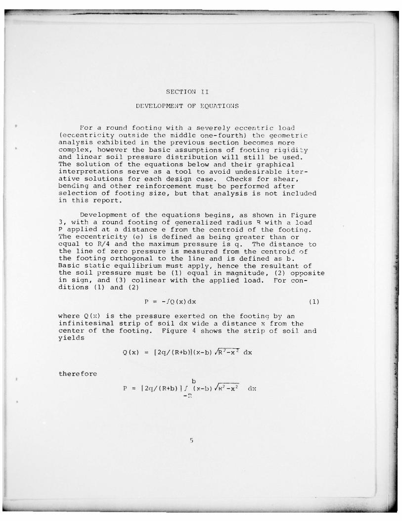
SECTION II
DI:VELOPME~ T OF PQETh,TIO~JS
For a round footinq wi th a severely eccentric load(eccentricity outside the middle one-fourth) the geometricanalysis exhibited in the previous section becomes morecomplex , howeve r the basic ass umptions of footing r ig idit yand l inear soil pressure d is t r ibution will st i ll be used.The solution of the eq uations below and their g raphicalinterpretation s serve as a tool to avoid undesirable iter-ative solutions for each design case. Check s for shear ,ben ding an d other r e i n f o rcement must be perf ormed af t e rselection of footing size, but that analysis is not includedin this report.
Development of the equations begins , as shown in Figure3 , wi th a round foot ing of general ized radi us ~ wi th a loadP applied at a distance e from the cen troid of the footing.The eccentricity (e) is defined as being greater than orequal to R/4 and the maximum pressure is q. The distance tothe line of zero pressure is measured from the centroid ofthe footing orthogonal to the line and is defined as b .Basic sLa tic equilibrium mus t apply , hence the resul tant ofthe soil pressure must be (1) equal in magnitude , (2) oppositein sign , and (3) colinear with the applied load. For con-di tions (1) and (2 )
P = —fQ(x )dx (1)
where Q ( ;~) is the pressure exerted on the foo tin g by aninfinitesimal strip of soil dx wide a distance x from thecenter of the footing. Figure 4 shows the strip of soil andyields
Q (x) = [2q/(R+b)](x-b) ~~~~~~ clx
thereforeb ____
P I 2 q / ( R + b ) f ( ~~— b ) cl:c
5
- —~~~~~~~~ —-- -

~V V — .:. - ~~~~~~~~ V _~_ ~~~~~~~~~ - : V __V :..._.. :
Figure 3. Generalized Round Footing
I
1’ iljure 4. PrI’ssur on Infinitesima l Stri p ot Soil
_ _
j- -V
- -- V V ~~~~~ -V ~~~~~~~~~~~~~~~ -

V -~~~~~
t~elative 1y simple integration and substitution of l i rC i t sgive
/2P = ~-q/(R+b)~ 2/3(R -h2 )
/ +R b [— ~~~~~~
—-~~- +sin b/R+1.571~ (2)
To main tain the resultant of the soil pressure co3.i~ ear w i ththe cccantric load (condiLion 3) , the distance to the centroidof tue volume defined by the right hand side of eauatlon ii)must be e, so that
— f x Q ( x ) d x ( 3 )e —
~~ Q(x)dx
The denominator of equat ion ( 3 ) is equation ( 2 ) and thenumera to r become s
[2q/ ( R+b) 1 f b (~~? -bx) p 2 -x 2 dxV
-R
V
again i n t e g r a t i o n and subs t i t u t i on of l imi t s gives
. 3/ ~ 2 2 2 1/x fl (x)dx = ~2q/ (R+h )j { b / l 2(R ’-.h2 ) 2-4-R /8 (b/R (P +b ) 2
+sin1 (b/R)+l.571} (4)
Divis ion of equation (4) by equat ion (2 ) give s t i c s o lu t i on to V
equation ( 3 ) as
e = bd3/12+R4/B (bd/R 2 +sin b/R+l.57) (5)d3/3+R 3b/ 2(cl/R2 +sin b/R+l.57)
where
d = / R 2 -h2
The s imul taneous sol ut ion of equa tions (2) V mn d ( 5 ) fo r P or eis not eas i ly obtained and the next section provide s a~t approachto make these equat ions u s e f u l .
7
_ _ — - --- -=~~~~~~~~~~~~~~~~~~~ _ - -
- -

SECT I ON I I I
RESU LTS
Equations developed in the previous section are r o treadily useable in that form , but with the development ofcomputers and programmable calculators , R and b can beeasily varied over a range of interest and e computed. Notet h a t e is not a func t ion of q and that P varies l inear lyw i t h q so tha t a n o r m a l i z e d P ( P/q ) can be found us ing gequal to u n i t y wh i l e v a r y i n g R and b. Figure 5 is a cartesianp lot of P normal ized versus e. Note the l imi t of e = R/ l .7 .That is where the zero piessure line crosses the centroid ofthe foo t ing (h = o ) . Beyond that a rb i t r a ry point , it isf e l t , tha t the bas ic a s s u m p t i o n s of foot ing rigidity andl i n e a r soil ur es su re d i s t r i b u t io n are not as re l iable .
Desiqn Aid Steps for use of Figure 5 follows :
( 1) Choose r a d i u s ( R ) in feet and depth of footing .
( 2 ) Compute e = I ’VP , where M is applied moment infoot -pounds and p is axial load at the bottom of the footingin pounds. Include wei ght of foot ing if applicable.
( 3 ) W i t h P and e en te r Fi gure 5 and f i n d P normalized V
(P/ q) -
( 4 ) Mu l t i p ly P/q by the allowable soil bearing pressurein pounds per square foot to obtain Pa.
( 5 ) If Pa > P, then P is adequate . The next smaller Rmay be tried. I f Pa < P, then P is inadequate and a larger Rmus t be chosen .
The above ~s onl y a suggested use of Figure 5 and theuser may use the chart according to need. The only unit V
rc~1ui red is the use of feet throughout. Feet may be convertedto meters by m u l t i p l j i n g by 0.305 and square feet to square V
rr~~ er3 i-” mu~ 4Viplyinq by 0.0929.
IV~~~15 r~~por t has shown tha t aids for design of round
feotings with ec c en t r i c loads can be developed. The basic:) r i n c L 11 r an be extended to o ther shape s such as an eccen-t r i c load on the d i a g o n a l of a rectangular footing. Proper
p

-- . -.-.
0~
I / II I /I I / ‘/ / :/ /I I I I’ N/ / 4?/ I A
/ / Qr’/ I/ / // /
/ / ~~~~~~~~~~
~~~~~~~~~~
Lu0—
I 00 0 0 0 0 ~ 0
2 0
d
- - - V _ —

— .~. ~~~~~~~~ —~~- _ -V~ ~~~~~~~~~~~~~~~~~~ _
0 V
p..
I’/I
I’—/I I v’I I -V.
/ I ‘a
I//
w0U
I U)III I1
‘I //
//
aIII 5— 0
/ z .• tO
/ Lii/-
~
Lu0
I .1 I I I I— I .
~~ Io 0 0 0 0 0 0 0 0 a0 ‘- 0b; d ( W a 3 z , 1 v~~ oN d
V _~~~~~~~~~~~~~~~~~~~ _ _
~~ ~~~~~~~~~~~~~~~~~~~~~~~~~~~~~~~~

- _ _ _ _ _ _ _ _ _ _ _ _
00
A
I ~~~~~~~II 0I,‘U
f / 0‘a
a0m
U)
0•._ • %
•4-100
‘a0 0
/ / :~~ :
Z i r ~
I I I I I I Io 0• 0 0 0 0 0 0 0 0 00 N 0 0
b,’d ( E ifl a3Z , 1~~~eIo~J p,

- -
~~~~~~~~~~~~~~~~~~~~~~~~~ ~~~~~~~~~~~~~~~~~~~~~~~~~~~ V VVVV V~ V~~~_ V _~~V VVV VV V~~ ~~ ~~~~~~~~~~~~~~~~~~~~ ~~~~~~~~~~~~~~~~ - ~~~~~~~~~~~~~~~~~~~~~~~~~
application of this design aid , as with other such aids ,requires a thorough understanding of its development. Toc u r t a i l improper use , personnel lacking der ivat ive knowledgeare discouraged from usinq these aids.
12
V ~~~~~~~~~~~~~~~~~~~~~~~~~~~~~~~~~~~~~~~~~~~~~~~~~~~~~~~~~~~~~~~~~~~~~ ~~~~~~~~~~~~~~~~~~~~~~~~~~~~~ -~~~~~~~~~~

______ - - VV ~ ~~~~~~~~~~~~~~~~~~~~~~~~~~~~~~~~~~~~~~~~~~~~~~~~~~~~~~~~~~~~ ~~~~~~~~~~ _ _
BIBLIOGRAP H Y
Leonards , G. A . , Editor , Foundation Engineering, New York , McGraw-Il ill ,1962.
Peck , Ralph B., Walter E. Hanson, and Thomas H. Thornburn , Founda tionEngineering, 2nd Edi tion , New York , John Wiley and Son s, 1974.
Teng , Wayne C., Foundation Desigp, New Jersey , Prentice-Hall , Inc., 1962.
Terzaghi , Karl , and Ralp h B. Peck , Soil Mechanics in Eng ineering Practice,2nd Edition , New York , John Wiley and Sons , 1968.
13(The reverse of this page is blank)
V ~~~~~V -- ~~~~~~~~~~~~~~~~~~~~~~~~~~~~~~~~~~~ ~~~~~~~~~~ _ _ _

V - V V ~~VV. _ V ,~~ ~V ~~~~~~~~~~~~~~~~~~~~~~~~~~~ - V ~~~~~~~~~~~~~~~~~~~~ -~~~ V V V~~~~ V V
INITIAL DISTRIBUTION
Hq USAF/PRE 1Hq MAC/DEMP 1Hq AFSC/DLXL 1Hq TAC/DEE 1
a Hq SAC/DEE 1Hq AFLC/DEE 1Hq ADCOM/DEE 1AUL/LDE 1Hq AAC/DEE 1AFIT, Tech Lib 1Hq USAFE/DEE 1Hq PACAF/DEE 1Hq USAFA/DFSLB 15 AF/DEE 17 AF/DEE 113 AF/DEE 1ADTC/DLODL 1DDC/TCA 12cEEDA/cNS 3cEEDA/PRT 1
I
15(The reverse of this page is blank)