n ver..u) corps of end neers waltham ma new … · dam, and consists of a three-bay concrete box...
TRANSCRIPT
AD-A142 623 A OA DM SPECTION PROGRAM WI NAINLDMI ET POND DAM MA I/I00169 NEPONSET N VER..U) CORPS OF END NEERS WALTHAM MANEW ENGLAND DIV APR 79
UNCISS ED FIG 13/1 L
EE7EEEEE

r=
IIII ' L . .
MICROCOPY RESOLUTION TEST CHART
~1

PHOTOGRAPH THIS SHEET
INzo
No oo, Mtssc~c.6 s Wi'L6e ?osd la~mI DOCUMENT IDENTIFICATION Al ocq
DISTIBUTION STATEMENT AApproved for public relea.;
Distribution Unlimited
DISTRIBUTION STATEMENT
ACCESSION FORNTIS GRA&I
DTIC TABDTICUNANNOUNCED (JJUSTIFICATION ELECTE
__ __ __ _ __ __ __ _ JUN 29 18
BYDDISTRIBUTION
D
AVAILABILITY CODESDIST AVAIL AND/OR SPECIAL DATE ACCESSIONED
DISTRIBUTION STAMP
84 '06 29 118
DATE RECEIVED IN DTIC
PHOTOGRAPH THIS SHEET AND RETURN TO DTIC-DDA-2
FORM DOCUMENT PROCESSING SHEETDTIC OCT 79 70A

I INCI ArS I 7 ESECURITY CLASSIFICATION OF THIS PAGE (When Do#& kneeed)
REPORT DOCUMENTATION PAGE READ INSTRUCTIONSBEFORE COMPLETING FORM
I. REPORT NUMBER 12.GOVT ACCESSION NO. 3. RECIPIENT'S CATALOG NUMBER
MA 00169 'IH/' 3 __ _ _ _ _ _ _
4 TITLE land Sub1i8e) I. TYPE OF REPORT a PERIOD COVERED
Neponset River Basin Norwood/Walpole, Mass. INSPECTION REPORTWillett Pond Dam
NA1MONAL PROGRAM FOR INSPECTION OF NON-FEDERAL 6 PERFORMINGONG. REPORT NUMBER
DAMS7, AUTNOR'() S. CONTRACT OR GRANT NUMBER(e)
U.S. ARMY CORPS OF ENGINEERSNEW ENGLAND DIVISION
S. PERFORMING ORGANIZATION NAME AND ADDRESS 10. PROGRAM LEIrENT. PROJECT. TASKAREA & WORK UNIT NUMBERS
II. CONTROLLING OFFICE NAME AND ADDRESS 12. REPORT DATEDEPT. OF THE ARMY, CORPS OF ENGINEERS April 1979NEW ENGLAND DIVISION, NEDED ;". NUMBER OF PAGES424 TRAPELO ROAD, WALTHAM, MA. 02254 72
T4. MONITORING AGENCY NAME & AOORESV(JI different #rol se Couiid ofic1e) 1S. SECURITY CLASS. (of tie ep rt)
UNCLASSIFIED116a. DECL ABSl FICATION/DOWN7RADING
SCHEDULE
It. DISTRIBUTION STATEMENT (1 tAie RePr#)
APPROVAL FOR PUBLIC RELEASE: DISTRIBUTION UNLIMITED
17. DISTRIBUTION STATEMENT (ol the obotra entered in lack 20. If differenI fow R Rp00)
11. SUPPLEMENTARY NOTESCover program reads: Phase I Inspection Report, National Dam Inspection Program;however, the official title of the program is: National Program for Inspection ofNon-Federal Dams; use cover date for date of report.
Is. KEY WORoS (Cns,.., en ,vere, aide to ne.eee an iden.ify by bl ck uumbe)
DAMS, INSPECTION, DAM SAFETY,
Neponset River Basin, Willett Pond Dam
20. ABSTRACT (Cenftm an .,,revre., aide Of nese and idenif.y by block nmber)The impounding structures a- Willett Pond include a 900 ft.long, 25-ft. high main amwith a spillway and an outlet, and a 1,900 ft. long, 13 ft. high dike. The structu eswere built in 1913. The dam & the dike contain a concrete core wall with the emba kmentsmadd of earth fill. The crest of the main dam varies from elevation 143.7 to 144.6and the crest of the dike varies from 142.0 to 142.8. The spillway is located at hesouth abutment of the dam, and consists of a three-bay concrete box culvert beneat theroadway. The combined width of the culvert openings is 24.9 ft., and the openings areeach 5.1 ft. high. Water discharges into a 220 ft. long discharge channel lined wi h
FOr* ' nu concreLe.DO FJAN75 1473 SOITION OF ' ,OV GAI OBIOSOLETC

I WILLETT POND DAM
M"A 00169
NEPONSET RIVER BASINNORWOOD/WALPOLE,MAS SACHUSETTS
PHASE I INSPECTION REPORTNATIONAL DAM INSPECTION
PROGRAM
I0

NATIONAL DAM INSPECTION
PROGRAM
PHASE I INSPECTION REPORT
BRIEF ASSESSMENT
Identification No.: MA00169
Name of Dam: Willett Pond
Town: Norwood and Walpole
County and State: Norfolk County, Massachusetts
Stream: Hawes Brook - Tributary of the Neponset River
Date of Inspection: December 5 and 12, 1978
The impounding structures at Willett Pond includea 900-foot long, 25-foot high main dam with a spillwayand an outlet, and a 1,900-foot long, 13-foot high dike.The structures were built in 1913. According to theavailable specification and drawings, both the dam anddike contain a concrete core wall with the embankmentsmade of earth fill. The crest of the main dam variesfrom elevation (El) 143.7 to 144.6, and the crest of thedike varies from El 142.0 to 142.8. An asphalt-pavedstreet (Brook Street) is on the crest of the main dam.The spillway is located at the south abutment of thedam, and consists of a three-bay concrete box culvertbeneath the roadway. The combined width of the culvertopenings is 24.9 feet, and the openings are each 5.1feet high. Stoplogs are mounted at the upstream end ofthe spillway. The crest of the stoplogs is at El 139.0and the crest of the spillway is El 137.7. Water dis-charges into a 220-foot long discharge channel linedwith stone and concrete. The outlet consists of two20-inch diameter, cast-iron conduits which discharge atthe toe of the dam. The pipes are located about 270feet from the south abutment of the dam. A gatehouse onthe downstream slope of the dam contains gate valves tocontrol flow. Discharge from the outlet flows through aParshall flume and into a flat swamp at the toe of the3 dam.
There are deficiencies which must be corrected toassure the continued performance of this dam. This
i WILLETT POND DAM
£

conclusion is based on the visual inspection of thesite, a review of available data, a review of the 1911and 1913 plans and specifications, and a review of opera-ting and maintenance procedures. Generally, the dam isin fair condition.
The following deficiencies were observed at themain dam: seepage at several locations along the down-stream toe, erosion on the upstream face of the damwhich has caused undermining of the crest, erosion onthe upstream and downstream slopes due to surface runofffrom the road on the crest, trees and brush on theupstream arnd downstream slopes, cracking and spalling ofgunite and concrete on the spillway, debris lodged onthe stoplogs of the spillway, erosion in the floor andIn the north side of the spillway channel, trees on thesides of the spillway discharge channel, and standingwater in the foundation of the gatehouse. Also, theearth dike is eroded locally on the upstream slope andcontains trees and brush on the upstream arnd downstreamslopes.
Based on Corps of Engineers' guidelines, the damhas been classified as "intermediate" and in the "high"fhazard category. Accordingly, a test flood equal to thefull probable maximum flood (PMF) was used for thisanalysis. Hydraulic analyses indicate that the spillway(without stoplogs) can discharge 740 cubic feet persecond (cfs) with the pond at El 142.1, which is theaverage low point on the crest of the dike. A testflood outflow of 4 380 cfs (the full Probable MaximumFlood (PM?)) with the pond at El 1'43.6 will not overtopthe main dam, but will overtop the dike by a maximum of
1.5 feet. The spillway (without stoplogs) can discharge17 percent of the test flood outflow before the dike isovertopped. With the stoplogs in place, the spillwaycan discharge 440 cfs or 10 percent of the test flood
before the dike is overtopped.
It is recommended that the Owner employ a qual-Iified consultant to evaluate the seepage which isoccurring through the embankment of the main dam. Theconsultant should also conduct a more detailed3 hydraulic! hydrologic study to evaluate raising thecrest of the dike or increasing the discharge capacityof the spillway at the main dam. The Owner shouldimmediately remove the stoploFs in front of the spillwayI and lower the pond by an arbitrary 2.7 feet (to El 135)below the crest of the spillway to reduce seepage3 pressure through the dam. The pond should be maintained
WILLETT POND DAMj

at El 135 until the above recommendations and the follow-ing remedial measures are completed: repair erosion onthe upstream slope of the dam and dike, constructsurface drainage control on both sides of the crest ofthe dam; selectively clear trees and brush from the dam,dike, and spillway discharge channel; repairconcrete/gunite on the spillway; repair erosion in thefloor and a breach in the side of the spillway dischargechannel; and dewater the foundation of the gatehouse anddetermine the location and magnitude of the leakage.The Owner should also implement a regular program ofinspection and maintenance and a warning system for thedar
The remedial measures outlined above and inSection 7 should be implemented by the Owner within aperiod of one year after receipt of this Phase 1 Inspec-tion Report. There are no recommended alternatives.
., ". \, ~ Edward M. Greco, P.E.
Project Manager
\.\<)8 3 Metcalf & Eddy, Inc.
A,/ Connecticut RegistrationONo. 08365
Approved by:
Stephh L. Bishop, P.E.
Vice President ,L. A
Metcalf & Eddy, Inc. T
Massachusetts Registration B
No. 19703 N
WILLETT POND DAM

This Phase I Inspection Report on Willett PondDam has been reviewed by the undersigned Review Boardmembers. In our opinion, the reported findings, con-clusions, and recommendations are consistent with theRecommended Guidelines for Safety Inspection of Dams,and with good engineering judgment and practice, and ishereby submitted for approval.
CHARLES G. TIERSCH, ChairmanChief, Foundation and MaterialsBranchEngineering Division
FRED J. RAVENS, JR., MemberChief, Design BranchEngineering Division
SAUL C. COOPER, MemberChief, Water Control BranchEngineering Division
APPROVAL RECOMMENDED:
JOE B. FRYARChief, Engineering Division
W~WILLETT POND DAM

PREFACE
This report is prepared under guidance containedin Recommended Guidelines for Safety Inspection of Dams,for a Phase I 71n-ve-stigation. Copies of these guidelinesmay be obtained from the Office of Chief of Engineers,Washington, D.C. 20314. The purpose of a Phase I Inves-tigation is to identify expeditiously those dams whichmay pose hazards to human life or property. The assess-ment of the general condition of the dam is based uponavailable data and visual inspections. Detailed investi-gations, and analyses involving topographic mapping,subsurface investigations, testing, and detailed compu-tational evaluations are beyond the scope of a Phase Iinvestigation; however, the investigation is intended toidentify any need for such studies.
In reviewing this report, it should be realizedthat the reported condition of the dam is based on obser-vations of field conditions at the time of inspectionalong with data available to the inspection team. Incases where the reservoir was lowered or drained priorto inspection, such action, while improving the sta-bility and safety of the dam, removes the normal load onthe structure and may obscure certain conditions whichmight otherwise be detectable if inspected under thenormal operating environment of the structure.
It is important to note that the condition of adam depends on numerous and constantly changing internaland external conditions, and is evolutionary in nature.It would be incorrect to assume that the present condi-tion of the dam will continue to represent the conditionof the dam at some point in the future. Only throughcontinued care and inspection can there be any chancethat unsafe conditions willbe detected.
Phase I inspections are not intended to providedetailed hydrologic and hydraulic analyses. In accor-dance with the established Guidelines, the Spillway TestFlood is based on the estimated "Probable Maximum Floodtfor the region (greatest reasonably possible storm run-off), or fractions thereof. Because of the magnitude andrarity of such a storm event,* a finding that a spillwaywill not pass the test flood should not be interpretedas necessarily posing a highly inadequate condition.The test flood provides a measure of relative spillwaycapacity and serves as an aid in determining the needfor more detailed hydrologic and hydraulic studies,considering the size of the dam, its general conditionsand the downstream damage potential.
WILLETT POND DAM

TABLE OF CONTENTS
Page
BRIEF ASSESSMENT
PREFACE
OVERVIEW PHOTO iii
LOCATION MAP iv
REPORT
SECTION 1 - PROJECT INFORMATION 1
1.1 General 11.2 Description of Project 11.3 Pertinent Data 6
SECTION 2 - ENGINEERING DATA 11
2.1 General 112.2 Construction Records 112.3 Operating Records ii2.4 Evaluation 12
SECTION 3 - VISUAL INSPECTION 13
3.1 Findings 133.2 Evaluation 15
SECTION 4 - OPERATING PROCEDURES 16
4.1 Procedures 164.2 Maintenance of Dam 164.3 Maintenance of Operating
Facilities 164.4 Description of Any Warning
System in Effect 174.5 Evaluation 17
SECTION 5 - HYDRAULIC/HYDROLOGIC 18
5.1 Evaluation of Features 18
WILLETT POND DAM

TABLE OF CONTENTS (Continued)
Page
SECTION 6 - STRUCTURAL STABILITY 22
6.1 Evaluation of StructuralStability 22
SECTION 7 - ASSESSMENT, RECOMM~vENDATIONS,AND REMEDIAL MEASURES 24
7.1 Dam Assessment 247.2 Recommendations 257.3 Remedial Measures 257.4 Alternatives 26
APPENDIXES
APPENDIX A - PERIODIC INSPECTION CHECKLIST
APPENDIX B - PLANS OF DAM AND PREVIOUSINSPECTION REPORTS
APPENDIX C - PHOTOGRAPHS
APPENDIX D - HYDROLOGIC AND HYDRAULICCOMPUTATIONS
APPENDIX E - INFORMATION AS CONTAINED INTHE NATIONAL INVENTORY OF DAMS
WILLETT POND DAM
it

NVILITI PONI) t)ANINORtWOOD. MSAI1SIF

0 cr0 C)
Er00
a Z4
Af z 4-9.z2 -
< <U (n
CL
LLIOM0 <0LL 44
C
ou
oui
< LLU LL0
z 'o
LLw loo CAH,

NATIONAL DAM INSPECTION
PROGRAM
PHASE I INSPECTION REPORT
WILLETT POND DAM
SECTION 1
PROJECT INFORMATION
1.1 General
a. Auhriy Public Law 92-367, dated August 8,1972 ,authorized the Secretary of the Army,through the Corps of Enginecrs, to initiate anational program of dam inspection throughoutthe United States. The New England Divison ofthe Corps of' Engineers has been assigned theresponsibility of supervising the inspection ofdams within the New England Region. Metcalf &Eddy, Inc. has been retained by the New EnglandDivision to inspect and report on selected damsin the State of Massachusetts. Contract No.DACW 33-79-C-0016, dated November 28, 1978, hasbeen assigned by the Corps of Engineers forthis work.
b. Purpose:
(1) Perform technical inspection and evalua-tion of non-Federal dams to identify con-ditions which threaten the public safetyand thus permit correction in a timelymanner by non-Federal interests.
(2) Encourage and assist the States tc ini-tiate quickly effective dam safety pro-gramns for non-Federal dams.
(3) Update, verify and complete the NationalInventory of Dams.
1.2 Description of Project
a. Location. The dam is located on Hawes Brook, a
tributary of the Neponset River. The town line
WILLETT POND DAM

between Norwood and Walpole crosses the axis ofthe dam (see Location Map). Most of the maindam is located in the Town of Norwood and thesouthern end of the mFn dam and the dike arein the Town of Walpole. These towns arelocated in Norfolk County, Massachusetts.
b. Description of Dam and Appurtenances. Theimpounding structures at Willett Pond Darn con-sist of the main dam, including a spillway andoutlet, and an earth dike (see Figures B-1through B-5 and photographs in Appendix C).
The main dam is a 900-foot long earthembankment with a maximum height of 25 feet atthe gatehouse. According to the specificationsand drawings for the dam, the embankmentcontains a concrete cutoff wall extending 14 to10 feet below the base of the embankment (seeFigures B-4 and B-5). An asphalt-paved streetis on the crest of the dam, which is 23 to 27feet wide. The crest of the dam varies from El143.7 to 1144.6. The section of the roadlocated in Norwood is called Brook Street, andthe section in Walpole is called BullardStreet. The upstream face slopes at 2:1(horizontal to vertical) and is covered withriprap. The downstream face slopes at 2.0:1 to2.5:1 and is covered with grass and vegetation.There is an area of rock and earth fill on thedownstream face of the dam about 250 feet northof the gatehouse. This may have been the siteof a tannery which was originally located atthe damn.
The spillway, located at the south abutment ofthe dam, is a three-bay concrete box culvertwhich extends under Bullard Street. Theapproach to the spillway has vertical, concretesidewalls extending 11 feet upstream. Woodenstoplogs are set at the entrance to the spill-way, with the top at El 139.0. The invert ofthe culvert forms a broad-crested weir at El137.7 at the upstream edge, sloping to El 136.6at the downstream edge. T1he culvert openingsare 5.1 feet high and have a combined width of24.9 feet (effective length of spillway). Thedischarge channel below the spillway is about220 feet long and 20 to 214 feet wide. The
WILLETT POND DAM
2

sides are concrete walls for a distance ofabout 40 feet downstream. Below that, thesides are made of earth which are covered withboulders that are grouted in place. The floorof the discharge channel slopes at about 8percent.
The low-level outlet for the dam consists oftwo 20-inch diameter, cast-iron conduits,extending from the upstream toe of the dam tothe downstream toe. The outlet pipes arelocated about 270 feet north of the southabutment of the dam. The downstream invert ofthe pipes is at El 118.7. A brick gatehouse islocated on the downstream slope of the dam andcontains a manually operated gate valve and agated bypass for each outlet pipe. The outletpipes discharge into a Parshall flume used tomeasure the volume of flow (see Figures B-6 andB-7). A device to record flow is locatedinside the gatehouse. Below the flume is astream bounded by trees and a swamp.
The dike is a 1,900-foot long earth embankmentlocated along the southeast shore of WillettPond (see Location Map). The dike has a maxi-mum height of 14 feet. According to the speci-fications and drawings for the dike, theembankmnent contains a concrete core wall about15 feet high. The crest of the dike is about15 feet wide and varies from El 142.0 to 142.8.The upstream face slopes at about 2:1 and iscovered with riprap. The downstream faceslopes at 2.4:1 and is covered with vegetation.
c. Size Classification. Willett Pond Dam is clas-sified in the "intermediate" category, since ithas a maximum height of 25 feet and a maximumstorage capacity of 2,785 acre-feet.
d. Hazard Classification. The valley downstreamof the dam is about 400 to 500 feet wide. Anearth dam 5 feet high is located about 800 feetdownstream, but it has been breached near thesouth abutment down to the stream bed. Asecond dam forming Ellis Pond is located about3,700 feet downstream of Willett Pond Dam.
WILLETT POND DAM
3

Concentrated residential development occursdownstream of the dam along both sides of thevalley (see Location Map). Most of the homesare built away from and at least 10 feet abovethe bed of Hawes Brook. However, some homesare lower and closer to the stream, especiallyalong the south side of the valley onMorningside and Orleans Roads and around EllisPond. Below the dam at Ellis Pond, Hawes Brookflows beneath Route 1A, and then through athickly developed area including an apartment
building and a complex of factories.
I The alignment of the dike is parallel toBullard Street which is a well-traveled road.About 20 residences are located downstream,about 200 and 500 feet from the dike.
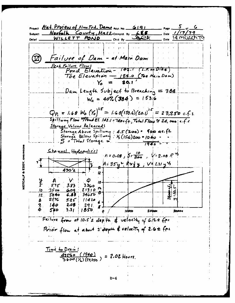
Failure of the main dam when the pond is at thea crest of the dike would produce a flood wave
about 10.5 feet high, 1,500 feet downstream.It is likely that this flood could result inexcessive property damage and the loss of morethan a few lives. Discharge below the EllisPond Dam could also affect the roadway andstructures farther downstream. Failure of thedike would produce a flood wave 3.5 feet highand would cause excessive property damage andpossible loss of life along Bullard Street.Accordingly, the dam has been placed in the"~high"? hazard category.
e. Ownership. The dam and dike have been ownedsince November 1953 by the Neponset ReservoirCorporation, a group of four industrial com-panies located along the Neponset River. Themember companies are: Bird & Son, Inc., EastWalpole; Hollingsworth & Vose Co., EastWalpole; the Kendall Co., Walpole; and DiamondInternational, Hyde Park. The current chairmanof the corporation is Mr. Malcolm White atHollingsworth & Vose Co., 112 WashingtonStreet, East Walpole Massachusetts 02032(telephone: (617) 666-0295). Mr. White grantedpermission to enter the property and inspectthe dam.
The pond originally was referred to as New Pondbut is now known as Willett Pond, out ofrespect for George F. Willett, former president
WILLETT POND DAM'4

of Winslow Brothers & Smith Company, underwhose administration the man-made pond wasconstructed.
f. Oprtos The dam is operated by personnelfrmBird & Son, Inc., East Walpole.
g. Pups fDm Willett Pond was originallyused by Wins ow Brothers and Smith Co. to pro-vide water for processing at a tannery. Later,the water was reportedly used to dilute indus-trial effluent from Hollingsworth & Vose Co.and Bird & Son, Inc., but who now recycle theirindustrial wastewater.
At the present time, water in Willett Pond isprimarily used to maintain a flow of 3 mgd(million gallons per day) in the NeponsetRiver as measured at a gaging station locatedabout 2 miles downstream. The water isreleased as needed, usually during July andAugust. The pond is also drawn down in thefall to provide storage for spring runoff. Thepond is also used for swimmiing arnd boating bythe abutting residents.
h. Design and Construction History. The dam anddike at Willett Pond were constructed in 1913for Winslow Brothers and Smith Co. A drawingand construction specifications were preparedin 1911 by Lucian A. Taylor, consultingengineer (drawing shown on Figure B-5). Alater drawing of the dam was prepared by A. L.Maddox, engineer, in 1913 (see Figure B-J4).These drawings show that both the dam and dikewere to be constructed with a concrete corewall extending below the bottom of theembankment. The base of the core wall isdescribed as carried to bedrock or to a"1watertight foundation". The specificationsstate the embankment was to be constructed of"1good gravel and sand such as may be procuredfrom the neighboring land". The spillway wasto be constructed of concrete with the crestfour feet below the top of' the embankment ofthe dam. The outlet pipes are shown as two20-inch diameter, cast-iron pipes encased inconcrete and having gate controls at the toe ofthe dam.
WILLETT POND DAM
5

During the period 1953 to 1970, several planswere proposed for diverting water from WillettPond and Hawes Brook to ponds near the Hollings-worth & Vose and the Bird & Sons factories.None of these plans was ever implemented.
In 1971, a Parshall flume was constructed belowthe outlet pipes for measuring discharge intoHawes Brook. Construction drawings prepared byMetcalf & Eddy, Inc. are shown on Figures B-6and B-7.
Spalling and cracking of the concrete had beendescribed in inspection reports dated May, 1968and July, 1973. Therefore, in about 1975, theconcrete walls of the spillway were reportedlyreconstructed by the Owner.
i. Normal Operating Procedures. Personnel fromBird & Son, Inc. reportedly visit the dam threeto four times a week. The stoplogs on thecrest of the spillway are permanently mounted;therefore, operation of the dam consists ofopening and closing the gates on the outletpipes. The gates are operated in summer andearly fall, as required, to maintain a flow of3 mgd at a gaging station located 2 milesdownstream on the Neponset River (see LocationMap). Personnel from Bird & Son, Inc. havekeys to the gaging station and check the flowperiodically during dry months. The pond isalso drawn down by 2 or 3 feet in the fall toprovide storage for runoff in the spring. Main-tenance personnel measure discharge through theParshall flume and record the discharge usingan instrument located in the gatehouse. Thegatehouse is kept locked.
1.3 Pertinent Data
a. Dramnage Area. The approximately 3,555-acre.5square mile) drainage area includes the
which flow into Willett Pond from the north(see Figure D-1 in Appendix). The topographyis gently rolling. About 12 percent of thedrainage area is ponds and swamps. Theremaining land is about half wooded and abouthalf cleared, mostly for residential develop-ment. There is moderate to thick residential
WILLETT POND DAM
6

development, especially north of Willett Pondinto Westwood and along the southwest shore ofthe pond. There are over 200 residences in thedrainage area.
b. Discharge. Normal discharge is over the spill-way and into a stone-lined channel leading toHawes Brook. The spillway is a three-bay con-crete box culvert with an effective length of24.9 feet. There are wooden stoplogs mountedjust upstream of the culvert, and the top ofthe stoplogs is at El 139.0. This dischargechannel is about 220 feet long and 20 to 24feet wide and discharges into Hawes Brookdownstream of the toe of the dam. The valleybelow the dam is a 400- to 500-foot wide swamp,heavily overgrown with brush and trees. Poolsand streams of water are present at severallocations below the dam, so that the bed ofHawes Brook is not clearly defined untilfarther downstream.
Discharge also occurs from the two 20-inch out-let pipes which discharge into a Parshall flumeand then into the swamp. This discharge is con-trolled by gate valves which are opened in thelate summer and fall for flood control.
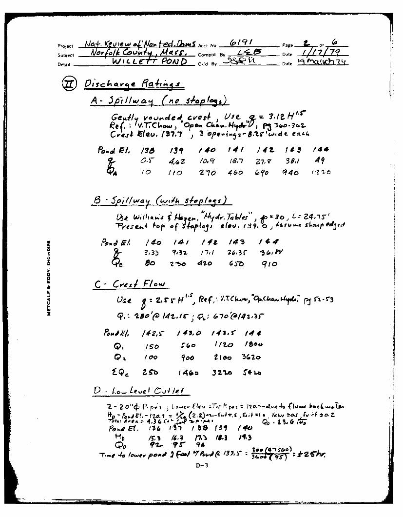
Hydraulic analyses indicate that the spillwaywithout stoplogs can discharge an estimated 750cfs with the pond at El 142.1, which is theaverage low point on the crest of the dike.The test flood outflow (full PMF) is estimatedto be 4,380 cfs with the pond at El 143.6.During the test flood, the main dam would notbe overtopped, but the dike would be overtoppedby a maximum of 1.5 feet. The pond could alsoflow out through a low area just south of thesouth abutment of the main dam and dischargedown Bullard Street. The low area is about 10to 30 feet wide and about 1.5 feet below thecrest of the main dam. The spillway withoutstoplogs can discharge 17 percent of the testflood before the dike is overtopped. With thestoplogs in place, the spillway can discharge440 cfs or 10 percent of the test flood beforethe dike is overtopped.
WILLETT POND DAM
7

Flood levels at the gaging station located down-stream on the Neponset River have been recordedsince October 1939. The maximum dischargerecorded on August 19, 1955 was 1,490 cfs forthe 35.2 square mile watershed includingWillett Pond. The dam at Willett Pond wasreportedly not overtopped or damaged in thisstorm.
c. Elevation (feet above Mean Sea Level (MSL)). Abenchmark was established at El 139.0 on top ofthe stoplogs at the spillway. This elevationwas estimated from a United States GeologicalSurvey (USGS) topographic map.
(1) Top dam - Main dam: 143.7 to 144.6
Dike section: 142.0 to 142.8
(2) Test flood pool: 143.5
(3) Design surcharge (original design):Unknown
(4) Full flood control pool: Not Applicable
(N/A)
(5) Recreation pool: 139.0 top of stoplogs
(6) Spillway crest (without stoplogs): 137.7
(7) Upstream portal invert diversion tunnel:N/A
(8) Streambed at centerline of dam: 118.7
(9) Tailwater: 119.0 - swamp below dam
d. Reservoir
(1) Length of maximum pool: 6,000 feet
(2) Length of recreation pool: 6,000 feet
(3) Length of flood control pool: N/A
e. Storage (acre-feet)
(1) Test flood surcharge (net): 1,227 at El143.6
WILLETT POND DAM
8

(2) Top of dam (El 142.1, average low point on
dike): 2,785
(3) Flood control pool: N/A
(4) Recreation pool (El 139.0, top of stop-logs): 2,140
(5) Spillway crest (El 137.7): 1,870
f. Reservoir Surface (acres)
*(1) Top dam: 208
*(2) Test flood pool: 208
(3) Flood control pool: N/A
(4) Recreation pool: 208
(5) Spillway crest (without stoplogs): 208
g. Dam
(1) Type - Main dam: earthfill embankment,concrete core wall, asphalt pave-ment on crest
- Dike section: earthfillembanknent, concrete core wall
(2) Length - Main dam: 900 feet- Dike section: 1,900 feet
(3) Height - Main dam: (maximum) 25 feet- Dike section: (maximum) 14 feet
(4) Top width - Main dam: 23 to 27 feet- Dike section: 13 to 16 feet
(5) Side slopes - Main dam: downstream 2:1to 2.5:1; upstream 2:1
- Dike section: downstream2.4:1; upstream 2:1
*Based on the assumption that the sulace area will notsignificantly increase with changes in pond elevationfrom 137.7 to 142.1.
WILLETT POND DAM
9

(6) Zoning (dam and dike): Concrete core wallwith embankment of pervious fill
(7) Impervious core (dam and dike): Concretecore wall
(8) Cutoff (dam and dike): Concrete core wallextends 4 to 10 feet below embankment tobedrock or impervious material.
(9) Grout curtain: None
h. Spillway
(1) Type: Broad-crested three-bay concretebox culvert with stoplogs mounted atupstream end
(2) Crest length: 24.9 feet
(3) Crest elevation: 137.7 (without stoplogs)139.0 (top of stoplogs)
(4) Gates: None
(5) Upstream channel: Vertical concrete sidewalls extending 11 feet upstream, floorcovered with sand and boulders
(6) Downstream channel: 20 to 24 feet wide,220 feet long; vertical, concrete sidewalls extending 40 feet downstream, thenearth sides lined with stone and concrete;floor is lined with stone and concrete
I. Regulating Outlets. The regulating outlet atthe dam consists of two 20-inch diameter,cast- iron conduits extending from the upstreamtoe of the dam to the downstream toe. Theinvert of the conduits at the downstream toe isat El 118.7. Flow Is controlled by gate valvesin a gatehouse on the downstream slope. Thegates are operated several times a year. Dis-charge is into a Parshall flume for measuringflow, and then into the swamp downstream.
WILLETT POND DAM10

SECTION 2
ENGINEERING DATA
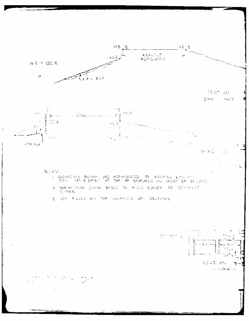
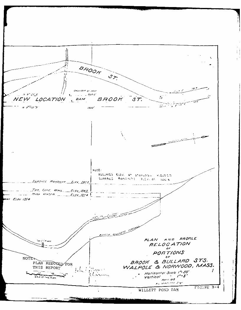
2.1 General. Several drawings, specifications andprevious inspection records are available for theWillett Pond Dam. A drawing, showing generalizedsections through the dam and dike (see Figure B-5)and a 10-page specification, both prepared in 1911by Lucian A. Taylor, were obtained from theMassachusetts Department of Public Works. Adrawing dated 1913 showing a plan and section ofthe main dam (see Figure B-4) was obtained from theTown Engineer's Office in Norwood. A drawing dated1952 showing a plan of the dike and propertyabutting the southern half of the pond was obtainedfrom Bird & Sons, Inc. Four sheets of drawingsdated 1971 for construction of the Parshall flume(see Figures B-6 and B-7) were prepared by Metcalf& Eddy, Inc. Previous inspection notes and aninspection report dated July 13, 1973 (see pagesB-8 through B-13) were also obtained from theMassachusetts Department of Public Works. No otherplans, specifications, or computations areavailable from the Owner, County, or State agenciesrelative to the design, construction or repair ofthis dam.
We acknowledge the assistance and cooperation ofpersonnel from the Massachusetts Division of Water-ways, the Massachusetts Department of Public Works,and the Norwood Town Engineer's Office; Mr. MalcolmWhite, representing the Neponset Reservoir Corpora-tion; and Messrs. Jim Moylon and John Hays of Bird& Son, Inc.
2.2 Construction Records. The only constructionrecords are the drawings referred to in Section 2.1and included in Appendix B. There are no as-builtdrawings for the dam, dike or appurtenantstructures.
2.3 Operaingecords. No operating records area alale, and there is no daily record kept of the
elevation of the pool or rainfall at the dam site.
WILLETT POND DAM

2.4 Evaluation
a. Availability. There is limited engineeringdata available.
b. Adequacy. The lack of detailed structural andconstruction data did not allow for adefinitive review. Therefore, the evaluationof the adequacy of this dam is based on reviewof available drawings and specifications,review of past inspection reports, visualinspection, past performance history, andengineering judgment.
c. Validity. Comparison of the available drawingswith the field survey conducted during thePhase I inspection indicates that the avail-able information is valid. There were minordiscrepancies between the 1911 and 1913drawings concerning the height and topelevation of the core wall in the main dam.This could not be checked in the field.
WILLETT POND DAM
12

SECTION 3
VISUAL INSPECTION
3.1 Findings
a. General. The Phase I Inspection of the dam atWITTe-tt Pond was performed on December 5, 1978.The inspection of the dike was conducted onDecember 12, 1978. A reinspection of the damand dike was done on March 21, 1979. A copy ofthe inspection checklist is in Appendix A.Previous inspections were conducted by NorfolkCounty in August, 1945, September, 19145, andMay, 1968. An inspection report prepared bythe Massachusetts Department of Public Works inJuly, 1973 is given in Appendix B (see pagesB-8 through B-13).
b. Dam. The dam consists of a 900-foot long,77-foot high earth embankment, with a spillwayat the south abutment and with an outlet andgatehouse located about 270 feet north of thesouth abutment. Also impounding the pond is anearth dike about 1,900 feet long and 13 feethigh located just south of the main dam.
The main dam is in fair condition. The areanear the downstream toe is wet and soft.Several locations of seepage were observedalong the toe from the spillway to the fillarea north of the gatehouse. In March, 1979,two streams of seepage were also flowing fromthe base of the fill area, as shown on FigureB-1. A rectangular, stone-lined hole islocated just downstream of the fill, and may bean abandoned outlet. A stream of orange wateris flowing from this opening southward intoHawes Brook. Much of the area below the dam isa swamp which extends downstream and appears tobe a natural feature. The toe of the embank-ment may have been constructed on or adjacentto organic material, however, the core wallprobably extends below the swamp level.
The most obvious deficiency at the main dam isthe severe erosion of the upper portion of theupstream face near the crest. This erosion hasundermined portions of the roadway, caused
WILLETT POND DAM
13
tilting of the fence along the edge of the roadand washing of soil down over the riprap.Other than wave action, this erosion isprobably due to surface runoff from the road,which has no curb or drainage system. Thesurface of the road is cracked, irregular, andpatched in places. The riprap on the upstreamslope of the dam is mostly intact. A fewpieces are missing, but there is no filling orchinking between the stones. Small trees andbrush are growing along the entire length ofthe upper upstream slope.
The downstream slope of the dam contains amoderate growth of brush and small oak trees,except in the vicinity of the gatehouse. Sur-face runoff from the road has eroded gullieslocally and one section of the fence along thedownstream edge of the crest is tilted down-stream.
The embankment of the dike is in faircondition. The upstream slope is covered withriprap, but footpaths and wave erosion havecaused local sloughing. Birch trees aregrowing along most of the upstream edge of thecrest. The downstream slope is covered by amoderate to thick growth of trees and brush.No seepage was observed along the dike.
c. Appurtenant Structures. The spillway for themain dam is a three-bay box culvert beneath theroad on the crest. Although the concrete wallswere recently resurfaced with gunite, crackingand erosion has occurred on the lower portionof the approach walls upstream of the spillwayand on the invert of the box culvert (see photo-graphs 7 and 8 in Appendix C). During a sub-sequent visit to the dam in March 1979, a treestump and other dead wood were caught on thestoplogs of the spillway.
The outlet for the dam is two 20-inch diametercast-iron pipes which discharge at the down-stream toe into a Parshall flume. A gatehouseis located on the downstream slope and containsmanually operated valves to control flow. Thegatehouse is in good condition and kept locked.The outlet pipes in the foundation of the gate-house are submerged in standing water. The
WILLETT POND DAM
14

outlets were discharging at the time of inspec-tion and could not be examined closely. Theflume is in good condition, although someerosion and spalling has occurred on the insideof the concrete walls. Water is seeping out ofthe flume through a construction joint on theupstream wall, forming a pool of water outsidethe wall.
d. Reservoir Area. The area around Willett Pondcontains sections of moderate and thick residen-tial development. There are about 50 resi-dences around the pond. It is possible thatfuture development could occur, especiallyalong the northwest portion of the shoreline.The land is about half wooded and about halfcleared, with slopes ranging from 4 to 10percent.
e. Downstream Channel. 'The discharge channelbelow the spillway is lined with stone andvoids are filled in with concrete. Severallarge holes 1 to 3 feet deep have been erodedin the floor of the discharge channel (seephotograph) I in Appendix C). On both sides ofthe channel, trees are growing which could falland partially block the channel during a flood.Near the downstream end of the channel, thenorth side has been eroded and, during theMarch 1979 visit, water was discharging throughthe side and flowing upstream toward the toe ofthe dam.
Water discharging from the Parshall flume flowsinto a swamp, although some water pools aroundthe outside of the flume. Around anddownstream of the flume, the area is flat,swampy and thickly wooded.
3.2 Evaluation. The above findings indicate that theisTin fair condition and that there are several
deficiencies which require attention. It isevident that the dam is not adequately maintained.Recommended measures to improve these conditionsare stated in Section 7.3.
WILLETT POND DAM
15

SECTION 4
OPERATING PROCEDURES
4.1 Procedures. Personnel from Bird & Son, Inc.reportedly visit the dam three to four times aweek. Normal procedures at the dam consist ofseasonally operating the outlets to maintain adownstream discharge and to provide storage forspring runoff. A minimum flow of 3 mgd is main-tained as measured at a gaging station locatedabout 2 miles downstream on the Neponset River. Toaccomplish this, personnel check the flow at thegaging station periodically during dry months. Theoutlets are opened as required, usually in July andAugust. The pond is also reportedly drawn down by2 or 3 feet in the late fall.
4.2 Maintenance of Dam. Periodic maintenance of thedam has been conducted in the past. Trees andbrush have been kept cleared from the downstreamslope in the vicinity of the gatehouse. There isalso evidence of past clearing of trees and brushin other areas on both the upstream and downstreamslopes. However, subsequent growth has occurred.About two or three years ago, the concrete on thespillway and side walls of the downstream channelwas repaired and resurfaced with gunite.
Present conditions at the dam indicate that it hasnot been adequately maintained. Seepage wasobserved at several locations along the downstreamtoe of the embankment. Erosion has occurred on theupstream edge of the dam, causing undermining ofthe road, loss of some riprap and tilting of thefence along the road. Trees and brush are growingon the upstream and downstream slopes of the dam.The gunite and concrete on the spillway is crackedand eroded below the level of the stoplogs. Thefloor and north side of the discharge channel areeroded, and trees are lining both sides of thechannel. The dike contains localized erosion onthe upstream face and growth of trees on the up-stream and downstream slopes.
4.3 Maintenance of Operating Facilities. The outletpipes are operated regularly. The control valvesare located inside a building which is kept locked
WILLETT POND DAM
16

and in good condition. The outlet pipes are sub-merged below standing water in the foundation ofthe gatehouse. There is some erosion and spallingof the inside walls of the flume located below theoutlet pipes.
4.4 Description of Any Warning System in Effect. Thereis no warning system in effect at this dam.
4.5 Evaluation. Although maintenance personnel visitthe dam regularly, the maintenance program isinadequate. There is no program of technicalinspections or any warning system in effect atWillett Pond Dam. This is extremely undesirableconsidering the dam is in the "high" hazardcategory. A regular program of inspection andmaintenance and a surveillance system for this damshould be implemented as recommended in Section7.3.
WILLETT POND DAM
17

SECTION 5
HYDRAULIC/HYDROLOGIC
5.1 Evaluation of Features
a. General. Willett Pond is impounded by a 900-Toot-long, 25-foot high earth dam and by a1,900-foot long earth dike. The crest of thedike was found to be 1 to 2 feet below thecrest of the main dam. The drainage area forthe pond is 5.55 square miles and is located insuburban communities with sections of thickresidential development. Bubbling Brook andMill Brook drain into the pond. The valleybelow the dam is wide and swampy. A low, earthdam, which has been breached, is located 800feet downstream. Ellis Pond Dam is located3,700 feet downstream, and the pond issurrounded by housing.
The maximum storage in Willett Pond iscalculated to be 2,785 acre-feet. The maximumflood level is unknown; there is no mention in
the County records of the dam being overtopped.The pond has been used for industrial purposesin the past. It is now used to control flow inthe Neponset River and for recreation.
b. Design Data. There are no hydraulic/hyrologiccomputations available for the design of thespillway at Willett Pond Dam.
c. Experience Data. Records for the gaging sta-tion downstream on the Neponset River indicatethat the maximum flood discharge since 1886 wasa rate of 1,490 cfs (42.3 cfs per square mile)on August 19, 1955. Personnel employed at thetime at Hollingsworth & Vose Co. state that thedam was not overtopped or damaged in thatstorm.
It was noted that during the December 1978inspection, the pond had been drawn down and,with a relatively dry fall, the level was at El132.8. During a return visit in March 1979,water was flowing over the stoplogs of thespillway (El 139.0), indicating a seasonalfluctuation of over 6 feet for the pond.
WILLETT POND DAM
18

d. 'Visual Observations. Water discharges overstoplogs at the upstream edge of the crest ofthe spillway. The spillway is a three-bay con-crete box culvert with an invert at El 137.7and an effective weir length of 24.9 feet. Thedischarge channel is 20 to 24 feet wide, 220feet long and the floor slopes at 8 percent.The sides of the channel are vertical, concretewalls, 5.4 feet high at the spillway andtapering down to less than 1 foot high werethey end about 40 feet downstream. Below this,the sides of the channel are 1 or 2 feet highand made of earth, lined with boulders andconcrete. The floor is lined with boulders andconcrete.
A tree stump and a few other pieces of deadwood were caught on the stoplogs of thespillway. Large holes 1 to 3 feet deep havebeen eroded in the floor of the dischargechannel. Trees are growing along both sides ofthe channel and could fall down during a flood.The lower 20 feet of the north side of thechannel has been eroded, allowing some water todischarge through the side and flow upstreamtoward the toe of the dam.
The outlet for the dam consists of two 20-inchconduits which discharge into a Parshall flumeand then into the swamp below the darn. Flow iscontrolled by gate valves which are located ina gatehouse and are operated several times ayear. The outlets were discharging at the timeof inspection. Some water was pooled aroundthe foundation of the flume.
A more detailed discussion of the condition ofthe dam and appurtenances is given in Section3, Visual Inspection.
e. Test Flood Analysis. Willett Pond Dam has beenplaced in the "intermediate" size category andin the "high" hazard category. In accordancewith the Corps of Engineers' guidelines, thefull PMF was used to evaluate the capacity ofthe spillway.
The PMF rate for Willett Pond Dam was deter-mined to be 1,000 cfs per square mile ofdrainage area. This calculation is based on
WILLETT POND DAM
19
the average slope of the drainage area of 1.5percent. The pond- plus-swamp area to drainagearea ratio of 12 percent, and the U.S. ArmyCorps of Engineers' guide curves for MaximumProbable Flood Peak Rates (dated December1977). Applying the full PMF rate to the 5.55square miles of drainage area results in acalculated peak flood flow of 5,550 cfs as thetest flood inflow. By adjusting the test floodinflow for surcharge storage, the maximumdischarge rate was established as 4,380 cfs(790 cfs per square mile) with the level of thepond at El 143.6.
Hydraulic analyses indicate that the spillway(without stoplogs) can discharge a maximum of740 cfs with the pond at El 142.1, which is the
average low point on the crest of the dike.This discharge is 17 percent of the test floodoutflow. During the test flood, the main damwould not be overtopped, but the dike would beovertopped by a maximum of 1.5 feet. The pondcould also flow out through a low area justsouth of the south abutment of the main dam anddischarge down Bullard Street. The low area isabout 10 to 30 feet wide and about 1.5 feetbelow the crest of the main dam. During thetest flood, discharge over the crest of thedike is estimated to be 3,320 cfs with a maxi-mum head of 1.5 feet. The depth at criticalflow would be 0.91 feet with a velocity of 5.41feet per second. With the stoplogs in place,the spillway can discharge 440 cfs or 10percent of the test flood before overtoppingthe dike.
The two 20-inch outlet pipes can discharge aflow of 96 cfs when the level of the pond is atthe crest of the spillway without stoplogs.Starting at that elevation, the outlets canlower the pond by 1 foot in about 25 hours.
f. Dam Failure Analysis. The peak discharge ratedue to failure of the main dam was calculatedto be 24,000 cfs, assuming a breach 154 feetwide and a head of 20 feet. Failure of themain dam would produce a flood wave obout 10.5feet high about 1,500 feet downstream. Thisflood could result in excessive damage to resi-dential and commercial property downstream of
WILLETT POND DAM
20

both Willett Pond and Ellis Pond Dams. Thefailure could also cause loss of more than afew lives in residences between Willett Pondand Ellis Pond Dams.
The peak discharge rate due to failure of thedike along Bullard Street was calculated to be4,600 cfs, assuming a breach 56 feet wide and ahead of 13.4 feet. Failure of the dike wouldproduce a flood wave about 3.5 feet high and200 feet wide. Failure of the dike couldresult in excessive damage to residences alongBullard Street and cause the loss of a fewlives.
For these reasons, the dam has been placed inthe "high" hazard category.
WILLETT POND DAM
21

SECTION 6
STRUCTURAL STABILITY
6.1 Evaluation of Structural Stability
a. Visual Observations. The evaluation of thestructural stability of the dam arnd dike atWillett Pond is based on a review of the avail-able data, a review of previous inspectionreports, and visual inspections conducted onDecember 5 and 12, 1978, and on March 21, 1979.
As discussed in Section 3, Visual Inspection,the dam and dike are in fair condition.Seepage was observed at several locations alongthe downstream toe of the dam. i.o seepage wasobserved at the toe of the dike. There were novisible signs of significant settlement ofeither structure. However, erosion of slopesand growth of trees and brush is occurring atboth sites.
b. Design and Construction Data. The dam and dikewere constructed in 1913. A specificationdated 1911 by Lucian A. Taylor describes themethods and materials proposed for construc-tion. Both embankments were to contain a corewall made of Portland cememt mixed with cleansand and gravel, less than 2-1/2 inches indiameter. The core wall at the main dam is 2feet thick at the top, which is 1.5 feet abovethe crest of the spillway (about El 139).Tedrawing dated 1913, however, shows the top ofthe core wall at 3.5 feet above the "floor ofthe wasteway" (about El 141). The thickness ofthe core wall increases 1 foot for each 10 feetvertically to the level of the outlet pipes (20feet on 1911 drawing, 17.5 feet on 1913drawing). The core wall is then extendeddownward at the same thickness for 4 to 10 feetinto bedrock or other "watertight" material.The core wall for the dike is constructed in asimilar way, with its top 1 foot above thecrest of the spillway (about El 139). The wallincreases thickness to a height of 15 feet, andthen is trenched into a "hard, water-tight"foundation with a thickness of 3 feet.
WILLETT POND DAM
22

The embankments are described as being madefrom local sand and gravel, with no stones morethan 6 inches in diameter and no vegetablematter. The embankments were to be laid in8-inch layers and "thoroughly rolled" toprevent settlement. The specification callsfor the ground beneath the embankments to becleared, grubbed, and all vegetable matter andmud removed to a "rfirm"f foundation, exceptbeneath the lower half of the downstream slope.The area along most of the downstream toe ofthe dam is a swamp. The toe of the embankmentmay have been constructed on or adjacent toorganic material, although the core wallprobably extends below the swamp level.
c. OperainRecords. There is no instrumenta-tio ofany type in the embankment at Willett
Pond Dam, and no instrumentation was everinstalled at this site. The performance of theembankment under prior loading can only beinferred by physical evidence at the site.
d. Post-Costruction Change s. During the period1953 to 170, several plans were proposed todivert water from Willett Pond and Hawes Brook
to ponds near the Hollingsworth & Vose and Bird& Sons factories. None of these plans was everimplemented.
The Parshall flume below the spillway was con-structed in 1971. Copies of the designdrawings are shown in Appendix B. Aninstrument to record the discharge is locatedinside the gatehouse. About 1975, the concreteon the spillway was repaired and resurfacedwith gunite.
e. Seismic Stability. The dam is located inSeimicZone No. 2. Because of its configura-
tion and the low head of water retained, aseismic analysis is not considered warranted.
WILLETT POND DAM
23

SECTION 7
ASSME, RECOMMThENDATIONS,
AND REMEDIAL MEASURES
7.1 Dam Assessment
a. Condition. Based upon a review of' availabledata, the visual inspection of' the site, andlimited operational or maintenance information,there are deficiencies which must be correctedto assure the continued performance of the dam.Seepage was observed at several locations alongthe downstream toe of the main dam. Severalother signs of distress were also observed:wave erosion on the upstream slope of the damcausing undermining of' the crest, erosion onthe upstream and downstream slopes due torunoff' from the road on the crest, trees andbrush on the upstream and downstream slopes,cracking and spalling of' gunite and concrete onthe spillway, debris lodged on the stoplogs of'the spillway, erosion of' the floor and thenorth side of the spillway discharge channel,trees on the sides of the spillway dischargechannel, and standing water around the outletpipes in the gatehouse. The earth dike iseroded locally on the upstream slope andcontains trees and brush on the upstream anddownstream slopes.
Hydraulic analyses indicate that the spillway(without stoplogs) can discharge an estimatedflow of 740 cf's with the pond at El 142.1,which is the average low point on the crest of'the dike. An outflow test flood (full PMF)will not overtop the main dam, but will overtopthe dike by a maximum of' 1.5 feet. The pondcould also flow out through a low area justsouth of the south abutment of' the main dam anddischarge down Bullard Street. The spillwaycan discharge 17 percent of' the test floodbefore the dike is overtopped. With thestoplogs in place, the spillway can discharge440 cf's or 10 percent of' the test flood beforethe dike is overtopped.
b. Adeqiuacy. The lack of detailed design andconstruction data did not allow for a definitive
WILLETT POND DAM
214

review. Therefore, the evaluation of theadequacy of this dam is based on a review ofthe available data, the visual inspection, pastperformance and engineering judgment.
c. Urgency. The recommendations and remedialmeasures outlined below should be implementedby the Owner within one year after receipt ofthis Phase I Inspection Report.
7.2 Recommendations. In view of the concerns over thecontinued performance of the dam, it Is recommendedthat the Owner employ a qualified consultant to:conduct a subsurface investigation to evaluate theseepage through the main dam, and conduct a moredetailed hydraulic/hydrologic study to evaluateraising the dike, increasing existing spillwaycapacity and/or adding an emergency spillway.
Recommendations on repairs and maintenance proced-ures are outlined below under Section 7.3, RemedialMeasures.
7.3 Remedial Measures
a. Operating and Maintenance Procedures. The damand appurtenant structures are not adequatelymaintained. It is recommended that the Owneraccomplish the following:
(1) immediately remove the stoplogs on thespillway and lower the pond by an arbi-trary 2.7 feet (to El 135) below the crestof the spillway to reduce seepage pressurethrough the dam. The pond should bemaintained at El 135 until the aboverecommendations and the following remedialmeasures have been completed.
(2) repair erosion on the upstream slopes ofthe dam and dike, replacing any missingriprap,
(3) construct a curb or drainage ditch alongboth sides of the roadway on the crest ofthe main dam to control surface drainage,
(4i) initiate a program of selective clearingof trees and brush from both slopes of themain dam and dike, and from the sides ofthe spillway discharge channel,
WILLETT POND DAM
25

(5) repair damaged gunite and concrete onwalls and crest of spillway,
(6) repair erosion in the floor and in thenorth side of the spillway dischargechannel,
(7) dewater the foundation of the gatehouseand determine the location and magnitude
of the leakage,
(8) implement a systematic program of main-tenance inspections. As a minimum, theinspection program should consist of amonthly inspection of the dam, dike andappurtenances,, supplemented by additionalinspections during and after severestorms. Maintenance should includeclearing of debris from the spillway anddischarge channel, clearing of trees andbrush from the slopes, and repair oferosion to slopes or to the concrete onthe spillway. All repairs and maintenanceshould be undertaken in accordance withall applicable State regulations.
(9) periodic technical inspections of this damshould be continued on an annual basis,
(10) institute a definite plan for surveillanceand a warning system during periods ofunusually heavy rains and/or runoff.
7.~4 Alternatives. There are no recommendedalternatives to implementing the recommendationsand remedial measures listed above.
WILLETT POND DAM
26

APPENDIX A
PERIODIC INSPECTION CHECKLIST
WILLETT POND DAM
-----. ; ; " N M

PERIODIC INSPECTIO:;
PARTY ORGANIZATION
WILLE-T POND DAM DATE 5 DEC. 1978
TIME 8:30 AM
WEATHER Clear, Breezy
W .- S .- E L E V .- 1 3 2 . . 1. I 9 I I . ..
*based on assumed benchmark at El.139.O
_____ "on top of stoplogs on spillway.
W. Checci 6. S. Pierce
D. Cole 7.
3. Komisarek 8.
. Larson 9.
H. Lord 10.
PROJECT FEATURE INSPECTED BY
Dam Embankment Larson/Komisarek
Spillway Larson/Komisarek
Dike Embankment Komisarek
'7
-"J
pae0V

PERIODIC INSPECTION CHECK LIST
PROJECT WILLETT POND DAM DATE 5 DEC. 1978
PROJECT FEATURE Dam Embankment NAME Komisarek
DISCIPLINE Geotechnical NAME Larsonu/s=upstream it.=leftd/s=downstream rt.=right
AREA EVALUATED CONDITIONS
DAM EMBANKMENT
Crest Elevation Varies from El. 143.7 to 144.6
Current Pool Elevation 132.8
Maximum Impoundment to Date Unknown
Surface Cracks Longitudinal cracks in road on crest
Pavement Condition Alligator cracking, asphalt patches
Movement or Settlement of Crest Settlement of road on both sides
Lateral Movement None visible
Vertical Alignment Numerous small dips in road
Horizontal Alignment Straight
Condition at Abutment and at t.abut.good-v.few trees, rolling
Concrete Structures Dround;rt.abut.good-many trees,rock
Indications of Movement of ence on u/sedge of crest leaningu/s
Structural Items on Slopes ence&telephone poles on d/sedge ofrest leaning d/s
Trespassing on Slopes ootpaths on d/s slope, rt. abut.
Sloughing or Erosion of Slopes u/s slope-consid.erosion&sloughlngor Abutments f road edge, also at one point onor Autmets /s eadve.
Rock Slope Protection - Riprap usriprap full length,minor pieces
Failures islodged,eroded near top of slope,Iiinm nt nrr of it u/s slope~no fillUnusual Movement or Cracking atknate-rialor near Toes None visible
Unusual Embankment or Downstream Seepage along toe from spillway
Seepage 2hannel to fill area north of gate
Piping or Boils
Foundation Drainage Features None
Toe Drains one visible
Instrumentation System one
page &-7o f_
PERIODIC INSPECTION CHECK LIST
PROJECT WILLETT POND DAM DATE 12 DEC. 1978
PROJECT FEATURE Dike Embankment NAME Komisarek
DISCIPLINE Geotechnical NAME__
AREA EVALUATED CONDITION
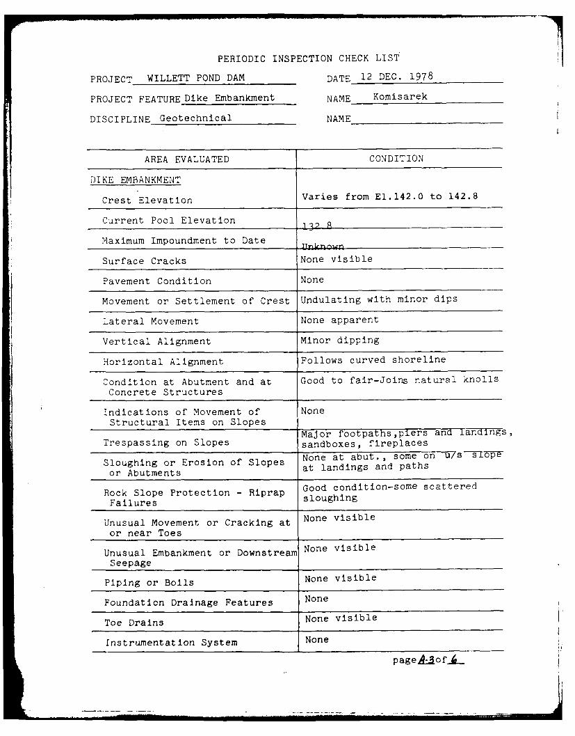
DIKE EMBANKMENT
Crest Elevation Varies from E1.142.0 to 142.8
Current Pool Elevation 1322R
Maximum Impoundment to Date
Surface Cracks None visible
Pavement Condition None
Movement or Settlement of Crest Undulating with minor dips
Lateral Movement None apparent
Vertical Alignment Minor dipping
Horizontal Alignment Follows curved shoreline
Condition at Abutment and at Good to fair-Joins natural knolls
Concrete Structures
Indications of Movement of NoneStructural Items on Slopes
Major footpaths,piers and landis,Trespassing on Slopes sandboxes, fireplaces
Sloughing or Erosion of Slopes None at abut., some on u/s siope
or Abutments at landings and paths
Rock Slope Protection - Riprap Good condition-some scattered
Failures sloughing
Unusual Movement or Cracking at None visible
or near Toes
Unusual Embankment or Downstream None visible
Seepage
Piping or Boils None visible
Foundation Drainage Features None
Toe Drains None visible
Instrumentation System None
pageA-of._

PERIODIC INSPECTION CHECK LIST
PROJECT WTTIFTT pOND DAM DATE 6 DEC. 1978
PROJECT FEATURE cDj11wjy qt nqm NAME Knmisarek
DISCIPLINE -ln~hn1n1 NAME T.rson
AREA EVALUATED CONDITION
OUTLET WORKS - SPILLWAY WEIR, Concrete side walls, floorAPPROACH AND DISCHARGE CHANNELS covered with sand, gravel,
i bouldersa. Approach Channel.
Fair to good-cracking & erosionGeneral Condition of lower portion of side walls
Loose Rock Overhanging None
Channel
Trees Overhanging Channel Some trees & brushSandy wltn bouiders, spit island
Floor of Approach Channel on u/s. side
b. Weir and Training Walls Triple box culvertRecent gun!te applicat-ionIISEVE7'
General Condition of 3palling&erosion below water line,
Concrete numerous cracks
Rust or Staining Some stainingSevere oelow water Tine,
Spalling especially on invert
Any Visible Reinforcing None
Any Seepage or Efflorescence Minor seepage 1 extensiveefflorescence
Drain Holes None
Rock rubble with concretec. Discharge Channel matrix
Very poor-everal extensive holes
General Condition due to scour, breach in left side
Loose Rock Overhanging Loose boulders rt.side, some
Channel natural rock outcrop in floor
Trees Overhanging Channel Large trees and brush each side
Floor of Channel Badly . eriorated,severe pitting,_rosion.and scour
Other Obstructions Channel discharges into,swamP area
pageA.1of _

PERIODIC INSPECTION CHECK LIST
PROJECT WILLETT POND DAM DATE 5 DEC. 1978
PROJECT FEATURE Control Tower NAME Komisarek
SICI PI, 1E Geotechnical NAME Larson
AREA EVALUATED CONDITION
.TLET WORKS - CONTROL TOWER Brick building with concrete founda-tion, windows bricked on d/s. side,
a. 7.ncrete and Structural locked door.
leneral Condition Good, vine-covered side
'ondition of Jcints Good
Spalling Minor amount,some due to vines
Visible Reinforcing None
Rusting or Staining of Algae stained concreteConcrete
Any Seepage or Efflorescence None
Joint Alignment Not applicable
Unusual Seepage or Leaks in None visible-outlet pipes submergedGate beneath standing water
Cracks None visible
Rusting or Corrosion of Steel Steel door sheathing rusted
b. Mechanical and Electrical Two gate valves, hand operatea,partially submerged in standing water
Air Vents None
Float Wells_____________________________None
Crane Hoist___ ___ ___ ___ ___ __ ___ ___ ___ ___ __ None
Elevator
Hydraulic System None
Service Gates None-two gate valves, one closed,
one partially open
Emergency Gates Nne
Lightning Protection System Nn__
Emergency Power System None
No lighting,chart recorder present'41ring and Lighting System to measure&record flow throughIn -)ate Chamber flume
-A P. A- S

PERIODIC INSPECTION CHECK LIST
PROJECT WILLETT POND DAM DATE 5 DEC. 1978
PROJECT FEATURE Discharge Flume NAME Komisarek
DISCIPLINE Geotechnical NAME Larson
AREA EVALUATED CONDITION
Parshall-flume-combinedOUTLET WORKS - OUTLET STRUCTURE poured concrete &cinder blocks.AND OUTLET CHANNEL Fair to good, some spall on
inside3eneral Condition of Concrete
MinorRust or Staining
Minor spalling above water line-Spalling interior walls.
Noted on cinder blocks andErosion or Cavitation nnnnt-rt-l..nt-Prinr walls
Visible Reinforcing Non
Any Seepage or Efflorescence Minor efflorescence on cinderAny__Seepage__o___Efflorescen __e _blnnr' mo-rtar
Minor at concrete cinder blockCondition at Joints Joint
Drain Holes NJneNatural,boulders visible with
ChanneltrahTrees and brush in and at
Loose Rock or Trees Over- channel edgehanging Channel
Condition of Discharge Poor to fair-natural,with minorChannel trash present
p age jo f__

APPENDIX B
PLANS OF DAM AND PREVIOUS
INSPECTION REPORTS
Page
Figure B-i, Plan of Main Dam B-1
Figure B-2, Sectons through Main Damn B-2
Figure B-3, Plan and Sections of Dike B-3
Figure B-4, Plan and Profile of Damdated April 1913 B-4
Figure B-5, Sections of Dam and Dike,dated August 1, 1911 B-5
Figure B-6 and B-7, Drawings ofWillett Pond Gage, dated April 1971 B-6
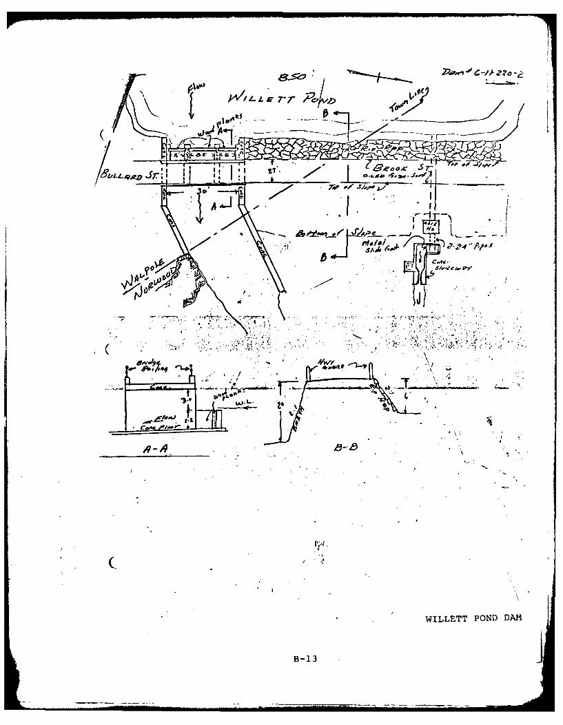
Inspection Report by Massachusetts Departmentof Public Works, dated July 13, 1973 B-8
WILLETT POND DAM

I L 7 ; ;\
03t~~~ %C
t7----

7-7
- = . . , _4 . .._-- -
I L7L A 7. , ,
_ '- ., , < - - - . - . - .
2 * : .s-'"
:-. . _ :_, ;A 2 i' '_ A-y - -_-
X~ .3
7
Xi.--..,- ' 4- -----..
14ETCILF A F:, I£ i A.!. ~GIE OYI
qAIIONA. PROGRA,'? OF INSPECTION OF NOU-FEO.OA.l
WILLETT POND DAMFIGURE 9-1 PLAN Of DAM
NEPONSEr RIVER __AS __HU EI]
J AtE: AS S1Ii3 I &IL: MARCH. IV ) .
=-7
c
I
K -fl -~
A
- ~
-
r~. L.7
~ (2~'~. r~A ~tc~' 3~ < 2 ~ p 0 ~ -, -- - '~ <- '~
- :.:
~ ~-.

K'I'
I- ICA INC --------- ImIi DI ie- U
~~N I. iI TAII PR1(100 IOf ILIS IW iIWIOf NON fI F D.I AU
WILI I PONDI 1DAM
I 16101 0f 8 SICIItN;, IIHI)IJ',I DA14
'~ 8I l Iii MFF'nW 41 RIAtR ISS7CM SE

ri
131
14Z ~ LV
CT,:
','
,/K. "L,? -dCb ' iI.

PON
t. -0 l F7
-. 4- -~:;7
C T i Ct- -
NA IIA RG A F IS EC I. FN NFND ',
WIL ET PO D A
FIGUR B- LNO IEADSETOSTR MDK
TRIBUTARY ~ ~ -. NEOSE IVRV (SCUSTS
SCLE AS SI HM RC ,17

-/O-q
fl I-. ~ ~A '/jJ - ~ VA
-~ NE-'V LCAF/O
11,A
1 , 11 IS R P R
-- - -- - - -- - -
NEL4/ LOCATION1 DAA- MAO~ T ~--+ - -
N 7T
4Y~U L4~ -t5
A /VN ANID Pi9 OA7Z
PO LAN RD FOR COI1 & LLLARV 2 S S
THIS REPORT W AALPOLE & AloR VVOOD, A-fASSY.- ,.~orza/1 Scale /,-'J*o'
--- ver-ticc'
WILLETT POND DAM FlIG7RE B-4

I ________________0 -___
a' 24.0* -_ --
t* tI
4>., ', )
~ ki.J- *
* __ - --. ~. - -
'A~. __ . .---- ,.. * ...-- ~-"7~
* -* I----- -,. - - -.---- ~ I
_________ * ** .. . - *, *.*.-* ._________ * .-.. ..
It..-.-' *.t..*.
*- .~- . I.I. .. ~i... .
~5o I~
* I
C-4'4T// LA~'L%'9/V/(A-7CN
0______________________________________________________ e~(j. ~
''C* -I.
~r.LI/Ot'/ 0P O,,rC * .*
I j
I I *
fV*~

#./ H -/, ??. ; ;V:. -.
Sections of Proposc2 Dam cnd DiVhci{or 'VV in o %v D r as c3 n d S ni -h Co. NLo r vvoo, i
.Scce .1 fect -o an 'inch.17
. .- .904. ,-Go,,o7' ZuI,#_, J.o'.
-~ c CueATY
NOTE:"PLAN REDUCED FOR WILLETT POND DAMTHIS REPORT
FIGURE B-5

W14E -L7 N
BRI10GARIL B1971LA Z
SM rNEERS
MILLEROPONEDD
'B-
- - -

WILLETT POND GAGE FIG. 2 OF '4
2 'kAIVCO VER
2P C C ACAc.'.T PL
6A 5/F V,1 F 4lST/r 1CA'!I-
4,C, I SOIL
AM'P, 0R,4P1V PZ AEOD~ AlDA/~
CONlTA'OL tlA:, VE5S TM BF I-OCA4 TED/4/ EXIS T/M6 ;Ar, TE /I01ISE.
SAM4-E EQIPMEAIT4AID 4,A,A1G4F114fN/AS 4T'A1EP01VSE7T RE~reVOIE 646F.
WILLETT POND DAMB- 7
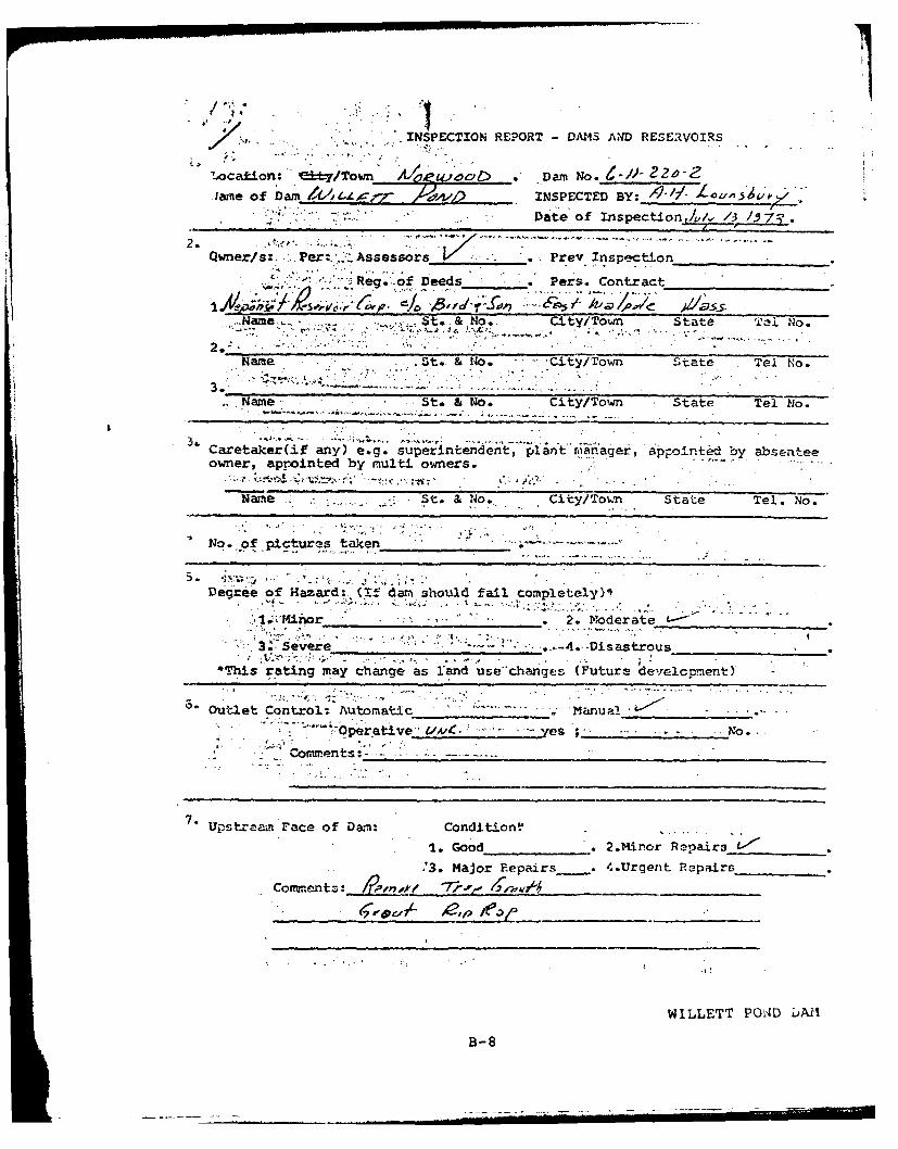
INSPECTION REPORT -DA145 AND RESERVOIRS
lame of Darn L ,r AI INSPECTED BY: ~ L~A~I~
Date of Inspection /v/ 1.5 /73.
Qwner/s:. Pe:..Assessors VPrey Inspection_________
R. - eg. -of Deed Pers. Contract__________
Name, -St* No... ,Clty/ToWn State TeNo
Name .St. & No. City/Town State Tel No.
Name St& & No* City/Town State Tel No.
Caretaker~if any) e g. superintendent, piant rmanager, appointed by absenteeowner, appointed by multi owners. ~~
ae St. &No.. City/TownM State Tel. No.
No. of pictures taken
Degree of Hazard: (If darm should fail completely),'
*1., Kior . ., .2. M0oderate L~
3." Severe . . -.. p......A. Disastrous_________*'his rating may change as land use-changes (Future develcpmnentY
"Outlet Control;: Automatic Man al .~
* T O___perative' £-'A'. e ;. ... o.- - Covvre nts-
7.Upstealn Face of Darn: Condition? .
1. Good . 2.Minor Ropairs L,-"'
'3. Major Repairs . 4.Urgent Repairs______
Corwto~ntz: ~'- &P
WILLETT POND UAil
B- 8

*DAN 110j. '"/ Z.
stra&i Eae of Da*: Condition: 1. Good * 2. Mnor Iapairs__,______
/ -~' -' *,. x~ri.A " .,. ihor Ropairq_ .. 4. Uront (ia.r
camata i ~
1hersency. Sp~lyt Cbnditlon: 1. G d. 2., ianor %pairs______
*~3. h.o ' .opirs.... 4. Urgent !.is.-
Uhter Invel 0 time or iwpsotion: L ft. abovz . balo'i_____
* ~ ,.top of da. prni15p7 w
- -. . . . ~Other__________
Stv=07 Of D fiCien_-i-.S "otad:"',"70.gh(troas an!4 bruch) on lbalm L I
/ OnimwI ilrzw erd WHashauts 7~- _____
1imare to aiopns or top r'f t 2--
-Cracked or' Daael ':as ozw i, dr-S,,,' "~~~L2 Z'Evidenice of 33pgrvidenos ofr Pl.pim2 "
Trash ard/or debris 1upcbing fiowAf_
QLoct~md or blockc =o1i',-yj/r.
WILLETT POND DAM
B-9

-4' ii
j temarks & Recovendations: (Fully Explain)
* ~p.
Overll, anvrio/
. -*-saf
5.~~~~~~~~~~ Ree'i nrud~tnlne xtsxla)
Recommen remova from ispetinlit
B-10
WLLETT OND DA

.17a~ro C Ji
woJYL orI nm
/ 2 ~etn TCo shet 11o. 3A- ..
134vd~ W*'x .'r lear cory of tape map wI'th )ctinoCrw ch~iri. 1ii7 i et,
ye T'i. earfa, of mih~eqgient rv- pair-s /1A-,K.
9, . 9,
Jrir.sal P'il?,4rg Are a: riO Acs y~!kth /o-'F
o.,andjyp7e ')f deliig 1tcated adjacent to parr! or reservoir-: e. nrsaomr heons e t c. .
.. . . ... pes: Up: tream Face /0
.9 . .. £bOwfltrenmT Face j r')
i .1dth across tam- 2-7
'lassification of Da b- IfIterl- erialsow-. St !~Mor.i-
T3 a stp, j. % flvf--x plain1:~ whic-h rt.l~i't'ii7kmot.i n tz- *uvent 'ja ::o-,qpete 'w fai1urn-3~Y2_ ~
WILLETT POND DM
B-il

.rDAM NO.________
to~ lifi&_;?4d properlty, hv ,vernt-of'omplete failure.
N m, of Bu~sinesses
Nyo ''of Tridutries Aa~~ ye_______* 'Mo of Utit~is /t4~n~ -Type_ ______
~Jther-_____________
V/tah fd' to~ this !forrr s owing &ection and. plan on
sheftt.
-7
WILT POD A
jBt12
I- - ------- -
k oi
- -r r Jv~t -
.s,.h 'NO
% 1 too/&,
v TO wo
~- L.
WILLETT POND DAM
B-13
APPENDIX C
PHOTOGRAPHS[
WILLETT POND DAM

NO. 1 CREST OF -DAM FROM SOUTH ABUTMENT
NO. 2 UPSTREAM SLOPE OF DAM
WILLETT POND DAM
c-1

NO. 3 UPSTREAM SLOPE AT SOUTH ABUTMENT
NO. 4 DO1WNSTREAM SLOPE OF DAM
WILLET? PO:ND DAN~l
C-2

NO. 5 VIEW OF GATE HOUSE AND DISCHARGE FLUME
NO. 6 VIEW OF PARSHALL DISCHARGE FLUME
WILLETT POND DAM
C-3

NO. 7 UPSTREAM VIEW OF SPILLWAY WITH FLASH BOARDS
NO. 8 INVERT OF BOX CULVERT
WII'7£T POND DAM
C-4
.... . -- "--- I .. ... . .[- li------...... .. _ -. .. - .. . . .. .

Il
NO. 9 UPSTREAM VIEW OF DISCHARGE CHANNEL
NO. 10 VIEW OF DIKE SOUTH OF DAM
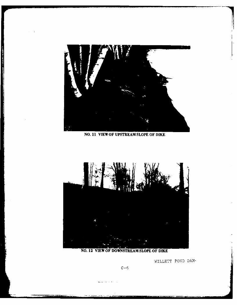
NO. 1 VIEW OF UPSTREAM SLOPE OF DIKE
NO. 12 VIEW OF DOWNSTREAM SLOPE OF DIKE
WILLETT POND DAM,
C-6

APPENDIX D
HYDROLOGIC AND HYDRAULICCOMPUTATIONS
Page
Figure D-1, Drainage Area Map for WillettPond Dam D-1
Hydrologic and Hydraulic Computations D-2
WILLETT POND DAM

~MEDFIELD, MASS. NORWOOD, MASS.QUADRANGLE QUADRANGLE
I,
FI.D1DANG0RA A ILT'PN

Project AJcI4 FCL/'C' 22~Oli ~ Dcq ACt No. ~j ,Page - of
Subject Alai -r I A4f Compid b~y Dale IZ/Zi170
Detail L LET O J C~kd, By ~ LDate 1tt j,14(
7 -,f FfOOA 1 J~ ~ ~~S-~c.~ Fuc4(ce,
1 To#( Oq't-.oj4 AveLq I" I ~ *'
7~A//ea 10 #-d(:1S +dotv-4L oco 0.30
3---7J8,~0 - 7
4- af U.4cAtd~ v~ i A.2
di75-IesP Flood 41~~ w Ie& Y.s -- ___
0 (4- Porct _5_ho-ooi_
7- spv;'Iwad cv-esl ete... /i 13T-7 )o .5op/oy s' I 131,o
Sov4 5I V o~ /l.,r fA e tP A~&eCf(iii'A-f- t' 0 a-4 I c C e,' r<,. t Zu e vg/A- 4- 4 c dr ai a .c.a
~)'S~oe~edeplU4 '. fee+- above- cr,4(-,a yecevt4x'v
9- flOIO Ali Pl..IMC 4 # 0It (Th7ooF'0d P .14 ' OIeCc(A
- F. P- C' S 7so- t9CD
D-2
Project Acct No. Page9 1
Subject M~/C~''74:Comptd. By _ _____Date ,f7 1Detail LI'LLC rtT PO&J Ck'd By Date 1-- fv<h Lt
Gem..i'/ vool,"eal eveSi Usfe-F =:7I
C.ej4 k~w /37.7 /Q~~~-.~ 9 ~d eac-4
P&M OfEll /?6 131 140 141 14&. 1-03 /4
4 /0 /o S2770 460O (a o q4o -'O
rop of 4F *(ef~u. 13.0') Astw-e. s~c~rey
z '3 7 3 /, 2, C 6,k
0
a ~ Cees/ F7/o w
ISO' 14t 0 4p,. &i.7o ?/3
-L..Lei~e I C~u4/.e I
12 20'4 P, r-,' Low.e v fUcu, -- Rp Ppe s 2--" f~uwwi
IS',3 4 /T /8. (3'T..~ 98 toaIf&~
71, oftOf 1O~w v P OR ' IZ 1
D- 3

Project R ue ( oi.Fd th Acct. No. G (9L Paeot_
Subject Ao4g o t.Mm Comptd. By Date 712 Z -/9t..Detailr WIL T P Ckd By _ _ _ _ _ __Date _ _ _ _ _ _
'A
0It~
a Ito
w
*A4Iz '
'. "4
WI
I L
-J.jU
y -6e 4-
"-D-4

Project V4)ICWuf~ P 4 6- Ac"i ct. No. -'fPage (0Subject A44A ~Comptd. By Date _tT
DetilCk'd. By Date[
/4'C4T 1-- t 4 2, 0 .SY' (/20 ,s fiJ~
3 =~9 2 S (fTr)
5W,/,Sro
AMitx, Dep4: s4,o 14~o 2_ r
0, 'f 4 ic VC 4s
At cre~S 7"t
TofaOo1 0nfL~tl
LoUv0" d v 'v ,vaf wpraj ffos 4 1
~I pf" Ieno-v~ Ioi/£edr
Q0~4 WI, tit L4 ~ -74 alc D
83s- /390 'G V
A4 ; Cr" e , Ie-v. /4.2.,i 1
S~e t. I3,9.3 7trApe- e poolldpe S w,
D- 5
Project AdIt4. PovLieH, ef m mi F-e-. Dmow t. No. ( i IPage 5-ofSubject Ma/*V4D'L COUVMI! MetfComptd. By -L-.---- Date 12Z2±..
Detail L4I L xTrT PbAjo Cd. By ~Date ~~YT
r® T I'' Vg0i -4 4$k
~ Levlbj4w (4re&xJLi,3
3~1ovoeA out5illwal 4,s'('2.C*) aO~ C~~56oe &*-(j~.ow. Sp;IIw&1 Y '(154) z ojo =
0
S' r7r 33 33(,oo %to IO Po~ C t)~ ~
516 40 ,8 3445-b
-z 7C' T Ir I(4t
4~io(/94) -?OZ Poo .rt
D- 6

Prp* AI&4. P'aview of M/ ~J Pe, . me Pag Li ... o~.
Sub%.ct Alo r fo Ik C-4dl#&LMCamftCm Byu L9 Da te -7Z 2i
I.4K~~~~I0 vii .4 W (J"= 4,#s (4-Dam-%~I te-I 2Uje *c r",, 10tG fi~ i.I
/,6 wo IY (
H-- $ ~ ftd f. I*a-__Aa__DT7.6a5b e iIA ( m '
uat plapV---- _____ ____
JI v As IC 1A r k e,,fwd
t- to- t
4ra~zoo
D- 7

APPENDIX E
INFORMATION AS CONTAINED INTHE NATIONAL INVENTORY OF
DAMS
WILLETT POND DAM