n1000v security
TRANSCRIPT
8/13/2019 n1000v Security
http://slidepdf.com/reader/full/n1000v-security 1/234
S e n d d o c u m e n t c o m m e n t s t o n e x u s 1 k - d o c f e e d b a c k @ c i s c o . c o m .
Americas Headquarters
Cisco Systems, Inc.170 West Tasman DriveSan Jose, CA 95134-1706USAhttp://www.cisco.comTel: 408 526-4000
800 553-NETS (6387)Fax: 408 527-0883
Cisco Nexus 1000V Security ConfigurationGuide, Release 4.2(1) SV1(4)February 17, 2012
Text Part Number: OL-22823-01

8/13/2019 n1000v Security
http://slidepdf.com/reader/full/n1000v-security 2/234
S e n d d o c u m e n t c o m m e n t s t o n e x u s 1 k - d o c f e e d b a c k @ c i s c o . c o m .
THE SPECIFICATIONS AND INFORMATION REGARDING THE PRODUCTS IN THIS MANUAL ARE SUBJECT TO CHANGE WITHOUT NOTICE. ALLSTATEMENTS, INFORMATION, AND RECOMMENDATIONS IN THIS MANUAL ARE BELIEVED TO BE ACCURATE BUT ARE PRESENTED WITHOUTWARRANTY OF ANY KIND, EXPRESS OR IMPLIED. USERS MUST TAKE FULL RESPONSIBILITY FOR THEIR APPLICATION OF ANY PRODUCTS.
THE SOFTWARE LICENSE AND LIMITED WARRANTY FOR THE ACCOMPANYING PRODUCT ARE SET FORTH IN THE INFORMATION PACKET THAT
SHIPPED WITH THE PRODUCT AND ARE INCORPORATED HEREIN BY THIS REFERENCE. IF YOU ARE UNABLE TO LOCATE THE SOFTWARE LICENSEOR LIMITED WARRANTY, CONTACT YOUR CISCO REPRESENTATIVE FOR A COPY.
The Cisco implementation of TCP header compression is an adaptation of a program developed by the University of California, Berkeley (UCB) as part of UCB’s publicdomain version of the UNIX operating system. All rights reserved. Copyright © 1981, Regents of the University of California.
NOTWITHSTANDING ANY OTHER WARRANTY HEREIN, ALL DOCUMENT FILES AND SOFTWARE OF THESE SUPPLIERS ARE PROVIDED “AS IS” WITHALL FAULTS. CISCO AND THE ABOVE-NAMED SUPPLIERS DISCLAIM ALL WARRANTIES, EXPRESSED OR IMPLIED, INCLUDING, WITHOUTLIMITATION, THOSE OF MERCHANTABILITY, FITNESS FOR A PARTICULAR PURPOSE AND NONINFRINGEMENT OR ARISING FROM A COURSE OFDEALING, USAGE, OR TRADE PRACTICE.
IN NO EVENT SHALL CISCO OR ITS SUPPLIERS BE LIABLE FOR ANY INDIRECT, SPECIAL, CONSEQUENTIAL, OR INCIDENTAL DAMAGES, INCLUDING,WITHOUT LIMITATION, LOST PROFITS OR LOSS OR DAMAGE TO D ATA ARISING OUT OF THE USE OR INABILITY TO USE THIS MANUAL, EVEN IF CISCOOR ITS SUPPLIERS HAVE BEEN ADVISED OF THE POSSIBILITY OF SUCH DAMAGES.
Cisco and the Cisco logo are trademarks or registered trademarks of Cisco and/or its affiliates in the U.S. and other countries. To view a l ist of Cisco trademarks, go to thisURL: www.cisco.com/go/trademarks . Third-party trademarks mentioned are the property of their respective owners. The use of the word partner does not imply a partnershiprelationship between Cisco and any other company. (1110R)
Any Internet Protocol (IP) addresses used in this document are not intended to be act ual addresses. Any examples, command display output, and figures included in thedocument are shown for illustrati ve purposes only. Any use of actual IP addresses in illustrative content is unintenti onal and coincidental.
Cisco Nexus 1000V Security Configuration Guide, Release 4.2(1) SV1(4) © 2011 Cisco Systems, Inc. All rights reserved.

8/13/2019 n1000v Security
http://slidepdf.com/reader/full/n1000v-security 3/234
S e n d d o c u m e n t c o m m e n t s t o n e x u s 1 k - d o c f e e d b a c k @ c i s c o . c o m .
iiiCisco Nexus 1000V Security Configuration Guide, Release 4.2(1) SV1(4)
OL-22823-01
C O N T E N T S
New and Changed Information xiii
Preface xv
Audience xv
Document Organization xv
Document Conventions xvi
Available Documents xvii
xix
Obtaining Documentation and Submitting a Service Request xix
xix
Security Overview 1-1
User Accounts 1-1
Virtual Service Domain 1-1
Authentication, Authorization, and Accounting (AAA) 1-2
RADIUS Security Protocol 1-2
TACACS+ Security Protocol 1-2
SSH 1-3
Telnet 1-3
Access Control Lists (ACLs) 1-3
Port Security 1-3
DHCP Snooping 1-3
Dynamic ARP Inspection 1-4
IP Source Guard 1-4
Managing User Accounts 2-1
Information About User Accounts 2-1
Role 2-1
User Name 2-3
Password 2-3
Check of Password Strength 2-3
Expiration Date 2-4

8/13/2019 n1000v Security
http://slidepdf.com/reader/full/n1000v-security 4/234
S e n d d o c u m e n t c o m m e n t s t o n e x u s 1 k - d o c f e e d b a c k @ c i s c o . c o m .
Contents
ivCisco Nexus 1000V Security Configuration Guide, Release 4.2(1) SV1(4)
OL-22823-01
Guidelines and Limitations 2-4
Default Settings 2-4
Configuring User Access 2-4
Enabling the Check of Password Strength 2-5
Disabling the Check of Password Strength 2-6
Creating a User Account 2-6
Creating a Role 2-8
Creating a Feature Group 2-10
Configuring Interface Access 2-12
Configuring VLAN Access 2-13
Verifying the User Access Configuration 2-15
Example Configuration 2-15
Additional References 2-16
Related Documents 2-16
Standards 2-16
MIBs 2-16
Feature History for User Accounts 2-16
Configuring VSD 3-1
Information About Virtual Service Domain3-1
Service Virtual Machine 3-1
Port Profiles 3-2
Guidelines and Limitations 3-3Default Settings 3-3
Configuring VSD 3-4
Configuring an Inside or Outside VSD Port Profile3-4
Configuring a Member VSD Port Profile3-7
Verifying the Configuration 3-8
Configuration Example 3-10
Additional References 3-10
Related Documents 3-11
Standards 3-11Feature History 3-11
Configuring AAA 4-1
Information About AAA 4-1

8/13/2019 n1000v Security
http://slidepdf.com/reader/full/n1000v-security 5/234
S e n d d o c u m e n t c o m m e n t s t o n e x u s 1 k - d o c f e e d b a c k @ c i s c o . c o m .
Contents
vCisco Nexus 1000V Security Configuration Guide, Release 4.2(1) SV1(4)
OL-22823-01
AAA Security Services 4-1
Authentication 4-2
Authorization 4-3
Accounting 4-3
AAA Server Groups 4-4
Prerequisites for AAA 4-4
AAA Guidelines and Limitations 4-4
Default Settings 4-4
Configuring AAA 4-4
Configuring a Login Authentication Method4-6
Enabling Login Authentication Failure Messages 4-7
Verifying AAA Configuration4-8
Example AAA Configuration 4-9
Additional References 4-9
Related Documents 4-9
Standards 4-9
Feature History for AAA 4-10
Configuring RADIUS 5-1
Information About RADIUS 5-1
RADIUS Network Environments 5-1
RADIUS Operation 5-2
RADIUS Server Monitoring 5-2Vendor-Specific Attributes 5-3
Prerequisites for RADIUS 5-4
Guidelines and Limitations 5-4
Default Settings 5-5
Configuring RADIUS Servers5-5
Configuring RADIUS Server Hosts 5-6
Configuring the Global RADIUS Key5-7
Configuring a RADIUS Server Key5-8
Configuring RADIUS Server Groups 5-9Enabling RADIUS Server Directed Requests 5-10
Setting the Global Timeout for All RADIUS Servers 5-12
Configuring a Global Retry Count for All RADIUS Servers5-13
Setting the Timeout Interval for a Single RADIUS Server5-14
Configuring Retries for a Single RADIUS Server 5-15
8/13/2019 n1000v Security
http://slidepdf.com/reader/full/n1000v-security 6/234
S e n d d o c u m e n t c o m m e n t s t o n e x u s 1 k - d o c f e e d b a c k @ c i s c o . c o m .
Contents
viCisco Nexus 1000V Security Configuration Guide, Release 4.2(1) SV1(4)
OL-22823-01
Configuring a RADIUS Accounting Server5-16
Configuring a RADIUS Authentication Server 5-17
Configuring Periodic RADIUS Server Monitoring 5-18
Configuring the Global Dead-Time Interval 5-20
Manually Monitoring RADIUS Servers or Groups 5-21
Verifying RADIUS Configuration 5-22
Displaying RADIUS Server Statistics 5-22
Example RADIUS Configuration 5-22
Additional References 5-22
Related Documents 5-22
Standards 5-23
Feature History for RADIUS 5-23
Configuring TACACS+ 6-1Information About TACACS+ 6-1
TACACS+ Operation for User Login6-2
Default TACACS+ Server Encryption Type and Preshared Key 6-2
TACACS+ Server Monitoring 6-3
Vendor-Specific Attributes 6-3
Cisco VSA Format 6-3
Prerequisites for TACACS+ 6-4
Guidelines and Limitations 6-4
Default Settings 6-4Configuring TACACS+ 6-5
Enabling or Disabling TACACS+6-8
Configuring Shared Keys 6-9
Configuring a TACACS+ Server Host 6-11
Configuring a TACACS+ Server Group 6-12
Enabling TACACS+ Server Directed Requests6-15
Setting the TACACS+ Global Timeout Interval6-16
Setting a Timeout Interval for an Individual TACACS+ Host 6-17
Configuring the TCP Port for a TACACS+ Host6-18
Configuring Monitoring for a TACACS+ Host6-20
Configuring the TACACS+ Global Dead-Time Interval6-21
Displaying Statistics for a TACACS+ Host6-22
Example TACACS+ Configuration6-23

8/13/2019 n1000v Security
http://slidepdf.com/reader/full/n1000v-security 7/234

8/13/2019 n1000v Security
http://slidepdf.com/reader/full/n1000v-security 8/234
S e n d d o c u m e n t c o m m e n t s t o n e x u s 1 k - d o c f e e d b a c k @ c i s c o . c o m .
Contents
viiiCisco Nexus 1000V Security Configuration Guide, Release 4.2(1) SV1(4)
OL-22823-01
Enabling the Telnet Server 8-2
Starting an IP Telnet Session to a Remote Device 8-3
Clearing Telnet Sessions 8-4
Verifying the Telnet Configuration 8-5
Additional References 8-5
Related Documents 8-5
Standards 8-6
Feature History for Telnet 8-6
Configuring an IP ACL 9-1
Information About ACLs 9-1
ACL Types and Applications 9-2
Order of ACL Application 9-2
About Rules 9-2Source and Destination 9-2
Protocols 9-3
Implicit Rules 9-3
Additional Filtering Options 9-3
Sequence Numbers 9-4
Statistics 9-4
Prerequisites for IP ACLs 9-5
Guidelines and Limitations 9-5
Default Settings9-5
Configuring IP ACLs 9-5
Creating an IP ACL 9-6
Changing an IP ACL 9-7
Removing an IP ACL 9-9
Changing Sequence Numbers in an IP ACL 9-10
Applying an IP ACL as a Port ACL9-11
Adding an IP ACL to a Port Profile9-12
Applying an IP ACL to the Management Interface 9-13
Verifying IP ACL Configurations 9-14
Monitoring IP ACL 9-15
Example Configurations for IP ACL 9-15
Additional References 9-15
Related Documents 9-16
Standards 9-16

8/13/2019 n1000v Security
http://slidepdf.com/reader/full/n1000v-security 9/234
S e n d d o c u m e n t c o m m e n t s t o n e x u s 1 k - d o c f e e d b a c k @ c i s c o . c o m .
Contents
ixCisco Nexus 1000V Security Configuration Guide, Release 4.2(1) SV1(4)
OL-22823-01
Feature History for IP ACL 9-16
Configuring a MAC ACL 10-1
Information About MAC ACLs 10-1
Prerequisites for MAC ACLs 10-1
Guidelines and Limitations 10-1
Default Settings 10-2
Configuring MAC ACLs 10-2
Creating a MAC ACL 10-2
Changing a MAC ACL 10-3
Removing a MAC ACL 10-5
Changing Sequence Numbers in a MAC ACL 10-6
Applying a MAC ACL as a Port ACL 10-7
Adding a MAC ACL to a Port Profile10-8Verifying MAC ACL Configurations 10-9
Monitoring MAC ACLs 10-10
Example Configurations for MAC ACLs 10-11
Additional References 10-11
Related Documents 10-12
Standards 10-12
Feature History for MAC ACL 10-12
Configuring Port Security 11-1
Information About Port Security 11-1
Secure MAC Address Learning 11-1
Static Method 11-2
Dynamic Method 11-2
Sticky Method 11-2
Dynamic Address Aging 11-2
Secure MAC Address Maximums 11-3
Interface Secure MAC Addresses 11-3
Security Violations and Actions 11-4
Port Security and Port Types 11-5
Result of Changing an Access Port to a Trunk Port 11-5
Result of Changing a Trunk Port to an Access Port 11-5
Guidelines and Limitations 11-5
Default Settings 11-6
Configuring Port Security 11-6

8/13/2019 n1000v Security
http://slidepdf.com/reader/full/n1000v-security 10/234
S e n d d o c u m e n t c o m m e n t s t o n e x u s 1 k - d o c f e e d b a c k @ c i s c o . c o m .
Contents
xCisco Nexus 1000V Security Configuration Guide, Release 4.2(1) SV1(4)
OL-22823-01
Enabling or Disabling Port Security on a Layer 2 Interface 11-6
Enabling or Disabling Sticky MAC Address Learning 11-8
Adding a Static Secure MAC Address on an Interface 11-9
Removing a Static or a Sticky Secure MAC Address from an Interface 11-10
Removing a Dynamic Secure MAC Address 11-11
Configuring a Maximum Number of MAC Addresses 11-12
Configuring an Address Aging Type and Time 11-14
Configuring a Security Violation Action 11-15
Recovering Ports Disabled for Port Security Violations 11-17
Verifying the Port Security Configuration 11-18
Displaying Secure MAC Addresses 11-18
Example Configuration for Port Security 11-18
Additional References 11-19
Related Documents 11-19
Standards 11-19
Feature History for Port Security 11-19
Configuring DHCP Snooping 12-1
Information About DHCP Snooping12-1
Overview 12-1
Trusted and Untrusted Sources 12-2
DHCP Snooping Binding Database 12-2
Relay Agent Information Option 12-3
High Availability 12-3
Prerequisites for DHCP Snooping 12-3
Guidelines and Limitations 12-3
Default Settings 12-4
Configuring DHCP Snooping 12-4
Minimum DHCP Snooping Configuration 12-4
Enabling or Disabling the DHCP Feature 12-5
Enabling or Disabling DHCP Snooping Globally 12-6
Enabling or Disabling DHCP Snooping on a VLAN 12-7
Enabling or Disabling DHCP Snooping MAC Address Verification 12-8
Configuring an Interface as Trusted or Untrusted 12-9
Configuring the Rate Limit for DHCP Packets 12-10
Detecting Ports Disabled for DHCP Rate Limit Violation 12-11
Recovering Ports Disabled for DHCP Rate Limit Violations 12-12

8/13/2019 n1000v Security
http://slidepdf.com/reader/full/n1000v-security 11/234
S e n d d o c u m e n t c o m m e n t s t o n e x u s 1 k - d o c f e e d b a c k @ c i s c o . c o m .
Contents
xiCisco Nexus 1000V Security Configuration Guide, Release 4.2(1) SV1(4)
OL-22823-01
Clearing the DHCP Snooping Binding Database 12-13
Clearing All Binding Entries 12-13
Clearing Binding Entries for an Interface 12-14
Relaying Switch and Circuit Information in DHCP12-15
Verifying the DHCP Snooping Configuration 12-16
Monitoring DHCP Snooping 12-16
Example Configuration for DHCP Snooping 12-16
Additional References 12-17
Related Documents 12-17
Standards 12-17
Feature History for DHCP Snooping 12-17
Configuring Dynamic ARP Inspection 13-1
Information About DAI 13-1About ARP 13-1
About ARP Spoofing Attacks 13-2
About DAI and ARP Spoofing13-2
Interface Trust and Network Security 13-3
Prerequisites for DAI 13-4
Guidelines and Limitations 13-4
Default Settings 13-5
Configuring DAI 13-5
Configuring a VLAN for DAI13-6Configuring a Trusted vEthernet Interface 13-6
Resetting a vEthernet Interface to Untrusted 13-8
Configuring DAI Rate Limits 13-9
Resetting DAI Rate Limits to Default Values 13-11
Detecting and Recovering Error-Disabled Interfaces13-12
Validating ARP Packets 13-13
Verifying the DAI Configuration 13-14
Monitoring DAI 13-15
Example DAI Configuration 13-15Additional References 13-17
Related Documents 13-17
Standards 13-17
Feature History for DAI 13-18

8/13/2019 n1000v Security
http://slidepdf.com/reader/full/n1000v-security 12/234
S e n d d o c u m e n t c o m m e n t s t o n e x u s 1 k - d o c f e e d b a c k @ c i s c o . c o m .
Contents
xiiCisco Nexus 1000V Security Configuration Guide, Release 4.2(1) SV1(4)
OL-22823-01
Configuring IP Source Guard 14-1
Information About IP Source Guard 14-1
Prerequisites for IP Source Guard 14-2
Guidelines and Limitations 14-2Default Settings 14-2
Configuring IP Source Guard 14-2
Enabling or Disabling IP Source Guard on a Layer 2 Interface 14-3
Adding or Removing a Static IP Source Entry 14-4
Verifying the IP Source Guard Configuration 14-5
Displaying IP Source Guard Bindings 14-5
Example Configuration for IP Source Guard 14-5
Additional References 14-5
Related Documents 14-5Standards 14-6
Feature History for IP Source Guard 14-6
Disabling HTTP Server 15-1
Information About the HTTP Server15-1
Guidelines and Limitations 15-1
Default Setting 15-2
Disabling HTTP Server 15-2
Verifying the HTTP Configuration15-3
Additional References 15-3
Related Documents 15-4
Standards 15-4
Feature History for Disabling the HTTP Server 15-4
Security Configuration Limits 16-1
I N D E X
8/13/2019 n1000v Security
http://slidepdf.com/reader/full/n1000v-security 13/234
S e n d d o c u m e n t c o m m e n t s t o n e x u s 1 k - d o c f e e d b a c k @ c i s c o . c o m .
xiiiCisco Nexus 1000V Security Configuration Guide, Release 4.2(1) SV1(4)
OL-22823-01
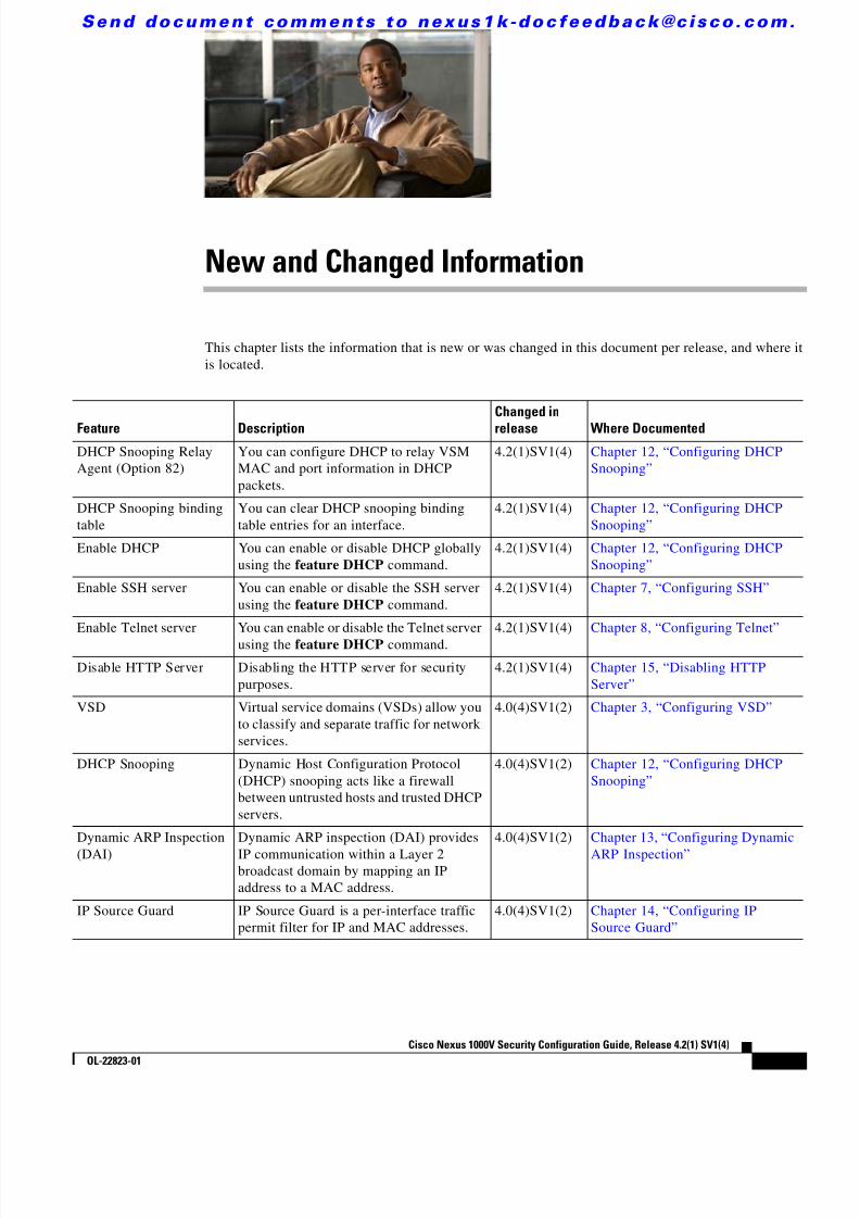
New and Changed Information
This chapter lists the information that is new or was changed in this document per release, and where itis located.
Feature DescriptionChanged inrelease Where Documented
DHCP Snooping RelayAgent (Option 82)
You can configure DHCP to relay VSMMAC and port information in DHCPpackets.
4.2(1)SV1(4) Chapter 12, “Configuring DHCPSnooping”
DHCP Snooping bindingtable
You can clear DHCP snooping bindingtable entries for an interface.
4.2(1)SV1(4) Chapter 12, “Configuring DHCPSnooping”
Enable DHCP You can enable or disable DHCP globallyusing the feature DHCP command.
4.2(1)SV1(4) Chapter 12, “Configuring DHCPSnooping”
Enable SSH server You can enable or disable the SSH serverusing the feature DHCP command.
4.2(1)SV1(4) Chapter 7, “Configuring SSH”
Enable Telnet server You can enable or disable the Telnet serverusing the feature DHCP command.
4.2(1)SV1(4) Chapter 8, “Configuring Telnet”
Disable HTTP Server Disabling the HTTP server for securitypurposes.
4.2(1)SV1(4) Chapter 15, “Disabling HTTPServer”
VSD Virtual service domains (VSDs) allow youto classify and separate traffic for networkservices.
4.0(4)SV1(2) Chapter 3, “Configuring VSD”
DHCP Snooping Dynamic Host Configuration Protocol(DHCP) snooping acts like a firewallbetween untrusted hosts and trusted DHCPservers.
4.0(4)SV1(2) Chapter 12, “Configuring DHCPSnooping”
Dynamic ARP Inspection
(DAI)
Dynamic ARP inspection (DAI) provides
IP communication within a Layer 2broadcast domain by mapping an IPaddress to a MAC address.
4.0(4)SV1(2) Chapter 13, “Configuring Dynamic
ARP Inspection”
IP Source Guard IP Source Guard is a per-interface trafficpermit filter for IP and MAC addresses.
4.0(4)SV1(2) Chapter 14, “Configuring IPSource Guard”

8/13/2019 n1000v Security
http://slidepdf.com/reader/full/n1000v-security 14/234
S e n d d o c u m e n t c o m m e n t s t o n e x u s 1 k - d o c f e e d b a c k @ c i s c o . c o m .
xivCisco Nexus 1000V Security Configuration Guide, Release 4.2(1) SV1(4)
OL-22823-01
New and Changed Information

8/13/2019 n1000v Security
http://slidepdf.com/reader/full/n1000v-security 15/234
S e n d d o c u m e n t c o m m e n t s t o n e x u s 1 k - d o c f e e d b a c k @ c i s c o . c o m .
xvCisco Nexus 1000V Security Configuration Guide, Release 4.2(1) SV1(4)
OL-22823-01
Preface
The Security Configuration document provides procedures for configuring security features, such asAAA, VSD, SSH, and so forth.
This preface describes the following aspects of this document:
Audience, page xv
• Document Organization, page xv
• Document Conventions, page xvi
• Available Documents, page xvii
• Obtaining Documentation and Submitting a Service Request, page xix
AudienceThis guide is for experienced network system users.
Document OrganizationThis document is organized into the following chapters:
Chapter and Title Description
Chapter 1, “Security Overview” Describes the security features.
Chapter 2, “Managing User Accounts” Describes how to configure user accounts.
Chapter 3, “Configuring VSD” Describes how to configure VSD.
Chapter 4, “Configuring AAA” Describes how to configure AAA.
Chapter 5, “Configuring RADIUS” Describes how to configure RADIUS.
Chapter 6, “Configuring TACACS+” Describes how to configure TACACS+.
Chapter 7, “Configuring SSH” Describes how to configure SSH.
Chapter 8, “Configuring Telnet” Describes how to configure Telnet.
Chapter 9, “Configuring an IP ACL” Describes how to configure IP access control lists(ACLs) for filtering traffic.

8/13/2019 n1000v Security
http://slidepdf.com/reader/full/n1000v-security 16/234
S e n d d o c u m e n t c o m m e n t s t o n e x u s 1 k - d o c f e e d b a c k @ c i s c o . c o m .
xviCisco Nexus 1000V Security Configuration Guide, Release 4.2(1) SV1(4)
OL-22823-01
Preface
Document ConventionsCommand descriptions use these conventions:
Screen examples use these conventions:
This document uses the following conventions for notes and cautions:
Note Means reader take note . Notes contain helpful suggestions or references to material not covered in themanual.
Chapter 10, “Configuring a MAC ACL” Describes how to configure MAC access control lists(ACLs) for filtering traffic.
Chapter 11, “Configuring Port Security” Describes how to configure port security.
Chapter 12, “Configuring DHCP Snooping” Describes how to configure DHCP snooping.Chapter 13, “Configuring Dynamic ARPInspection”
Describes how to configure Dynamic ARP Inspection.
Chapter 14, “Configuring IP Source Guard” Describes how to configure IP Source Guard.
Chapter 15, “Disabling HTTP Server” Describes how to disable HTTP server.
Chapter 16, “Security ConfigurationLimits”
Describes configuration limits for security features.
Chapter and Title Description
boldface font Commands and keywords are in boldface.
italic font Arguments for which you supply values are in italics.
{ } Elements in braces are required choices.
[ ] Elements in square brackets are optional.
x | y | z Alternative, mutually exclusive elements are separated by vertical bars.
string A nonquoted set of characters. Do not use quotation marks around the string orthe string will include the quotation marks.
screen font Terminal sessions and information the device displays are in screen font.boldface screenfont
Information you must enter is in boldface screen font.
italic screen font Arguments for which you supply values are in italic screen font.
< > Nonprinting characters, such as passwords, are in angle brackets.
[ ] Default responses to system prompts are in square brackets.
!, # An exclamation point (!) or a pound sign (#) at the beginning of a line of codeindicates a comment line.

8/13/2019 n1000v Security
http://slidepdf.com/reader/full/n1000v-security 17/234
S e n d d o c u m e n t c o m m e n t s t o n e x u s 1 k - d o c f e e d b a c k @ c i s c o . c o m .
xviiCisco Nexus 1000V Security Configuration Guide, Release 4.2(1) SV1(4)
OL-22823-01
Preface
Caution Means reader be careful . In this situation, you might do something that could result in equipmentdamage or loss of data.
Available DocumentsThis section lists the documents used with the Cisco Nexus 1000 and available on Cisco.com at thefollowing url:
http://www.cisco.com/en/US/products/ps9902/tsd_products_support_series_home.html
General Information
Cisco Nexus 1000V Documentation Roadmap, Release 4.2(1)SV1(4)
Cisco Nexus 1000V Release Notes, Release 4.2(1)SV1(4)
Cisco Nexus 1000V Compatibility Information, Release 4.2(1)SV1(4)
Cisco Nexus 1010 Management Software Release Notes, Release 4.2(1)SP1(2)
Install and Upgrade
Cisco Nexus 1000V Virtual Supervisor Module Software Installation Guide, Release 4.2(1)SV1(4)
Cisco Nexus 1000V Software Upgrade Guide, Release 4.2(1)SV1(4)
Cisco Nexus 1000V VEM Software Installation and Upgrade Guide, Release 4.2(1)SV1(4)
Cisco Nexus 1010 Virtual Services Appliance Hardware Installation Guide
Cisco Nexus 1010 Software Installation and Upgrade Guide, Release 4.2(1)SP1(2)
Configuration GuidesCisco Nexus 1000V License Configuration Guide, Release 4.2(1)SV1(4)
Cisco Nexus 1000V Getting Started Guide, Release 4.2(1)SV1(4)
Cisco Nexus 1000V High Availability and Redundancy Configuration Guide, Release 4.2(1)SV1(4)
Cisco Nexus 1000V Interface Configuration Guide, Release 4.2(1)SV1(4)
Cisco Nexus 1000V Layer 2 Switching Configuration Guide, Release 4.2(1)SV1(4)
Cisco Nexus 1000V Port Profile Configuration Guide, Release 4.2(1)SV1(4)
Cisco Nexus 1000V Quality of Service Configuration Guide, Release 4.2(1)SV1(4)
Cisco Nexus 1000V Security Configuration Guide, Release 4.2(1)SV1(4)
Cisco Nexus 1000V System Management Configuration Guide, Release 4.2(1)SV1(4)Cisco Nexus 1010 Software Configuration Guide, Release 4.2(1)SP1(2)
Programming Guide
Cisco Nexus 1000V XML API User Guide, Release 4.2(1)SV1(4)

8/13/2019 n1000v Security
http://slidepdf.com/reader/full/n1000v-security 18/234
S e n d d o c u m e n t c o m m e n t s t o n e x u s 1 k - d o c f e e d b a c k @ c i s c o . c o m .
xviiiCisco Nexus 1000V Security Configuration Guide, Release 4.2(1) SV1(4)
OL-22823-01
Preface
Reference Guides
Cisco Nexus 1000V Command Reference, Release 4.2(1)SV1(4)
Cisco Nexus 1000V MIB Quick Reference
Cisco Nexus 1010 Command Reference, Release 4.2(1)SP1(2)
Troubleshooting and Alerts
Cisco Nexus 1000V Troubleshooting Guide, Release 4.2(1)SV1(4)
Cisco Nexus 1000V Password Recovery Guide
Cisco NX-OS System Messages Reference
Virtual Security Gateway Documentation
Cisco Virtual Security Gateway for Nexus 1000V Series Switch Release Notes, Release 4.2(1)VSG(1)
Cisco Virtual Security Gateway, Release 4.2(1)VSG1(1) and Cisco Virtual Network ManagementCenter, Release 1.0.1 Installation Guide
Cisco Virtual Security Gateway for Nexus 1000V Series Switch License Configuration Guide, Release4.2(1)VSG1(1)
Cisco Virtual Security Gateway for Nexus 1000V Series Switch Configuration Guide, Release4.2(1)VSG1(1)
Cisco Virtual Security Gateway for Nexus 1000V Series Switch Command Reference, Release4.2(1)VSG1(1)
Virtual Network Management Center
Release Notes for Cisco Virtual Network Management Center, Release 1.0.1
Cisco Virtual Security Gateway, Release 4.2(1)VSG1(1) and Cisco Virtual Network ManagementCenter, Release 1.0.1 Installation Guide
Cisco Virtual Network Management Center CLI Configuration Guide, Release 1.0.1
Cisco Virtual Network Management Center GUI Configuration Guide, Release 1.0.1
Cisco Virtual Network Management Center XML API Reference Guide, Release 1.0.1
Network Analysis Module Documentation
Cisco Network Analysis Module Software Documentation Guide, 4.2
Cisco Nexus 1000V NAM Virtual Service Blade Installation and Configuration Guide
Network Analysis Module Command Reference Guide, 4.2
User Guide for the Cisco Network Analysis Module Virtual Service Blades, 4.2Cisco Network Analysis Module Software Release Notes, 4.2

8/13/2019 n1000v Security
http://slidepdf.com/reader/full/n1000v-security 19/234
S e n d d o c u m e n t c o m m e n t s t o n e x u s 1 k - d o c f e e d b a c k @ c i s c o . c o m .
xixCisco Nexus 1000V Security Configuration Guide, Release 4.2(1) SV1(4)
OL-22823-01
Preface
Obtaining Documentation and Submitting a Service RequestFor information on obtaining documentation, submitting a service request, and gathering additionalinformation, see the monthly What’s New in Cisco Product Documentation , which also lists all new andrevised Cisco technical documentation, at:
http://www.cisco.com/en/US/docs/general/whatsnew/whatsnew.html
Subscribe to the What’s New in Cisco Product Documentation as a Really Simple Syndication (RSS) feedand set content to be delivered directly to your desktop using a reader application. The RSS feeds are a freeservice and Cisco currently supports RSS Version 2.0.

8/13/2019 n1000v Security
http://slidepdf.com/reader/full/n1000v-security 20/234
S e n d d o c u m e n t c o m m e n t s t o n e x u s 1 k - d o c f e e d b a c k @ c i s c o . c o m .
xxCisco Nexus 1000V Security Configuration Guide, Release 4.2(1) SV1(4)
OL-22823-01
Preface

8/13/2019 n1000v Security
http://slidepdf.com/reader/full/n1000v-security 21/234
C H A P T E R
S e n d d o c u m e n t c o m m e n t s t o n e x u s 1 k - d o c f e e d b a c k @ c i s c o . c o m .
1-1Cisco Nexus 1000V Security Configuration Guide, Release 4.2(1) SV1(4)
OL-22823-01
1Security Overview
This chapter provides an overview of the following security features used with the Cisco Nexus 1000V:
• User Accounts, page 1-1
• Virtual Service Domain, page 1-1
• Authentication, Authorization, and Accounting (AAA), page 1-2
• RADIUS Security Protocol, page 1-2
• TACACS+ Security Protocol, page 1-2
• SSH, page 1-3
• Telnet, page 1-3
• Access Control Lists (ACLs), page 1-3
• Port Security, page 1-3
• DHCP Snooping, page 1-3
• Dynamic ARP Inspection, page 1-4
• IP Source Guard, page 1-4
User AccountsAccess to the Cisco Nexus 1000V is accomplished by setting up user accounts that define the specificactions permitted by each user. You can create up to 256 user accounts. For each user account, you definea role, user name, password, and expiration date. For information about configuring and managing useraccounts, see Chapter 2, “Managing User Accounts.”
Virtual Service DomainA virtual service domain (VSD) allows you to classify and separate traffic for network services, such asfirewalls, traffic monitoring, and those in support of compliance goals such as Sarbanes Oxley. Forinformation about configuring and managing VSD, see Chapter 3, “Configuring VSD.”

8/13/2019 n1000v Security
http://slidepdf.com/reader/full/n1000v-security 22/234
S e n d d o c u m e n t c o m m e n t s t o n e x u s 1 k - d o c f e e d b a c k @ c i s c o . c o m .
1-2Cisco Nexus 1000V Security Configuration Guide, Release 4.2(1) SV1(4)
OL-22823-01
Chapter 1 Security OverviewAuthentication, Authorization, and Accounting (AAA)
Authentication, Authorization, and Accounting (AAA)AAA, called Triple A, is an architectural framework for configuring a set of three independent,consistent, and modular security functions.
• Authentication—Provides the method of identifying users, including login and password dialog,challenge and response, messaging support, and, depending on the security protocol that you select,encryption. Authentication is the way a user is identified prior to being allowed access to thenetwork and network services. You configure AAA authentication by defining a named list ofauthentication methods and then applying that list to various interfaces.
• Authorization—Provides the method for remote access control, including one-time authorization orauthorization for each service, per-user account list and profile, user group support, and support ofIP, IPX, ARA, and Telnet.
Remote security servers, such as RADIUS and TACACS+, authorize users for specific rights byassociating attribute-value (AV) pairs, which define those rights, with the appropriate user. AAAauthorization works by assembling a set of attributes that describe what the user is authorized toperform. These attributes are compared with the information contained in a database for a givenuser, and the result is returned to AAA to determine the user’s actual capabilities and restrictions.
• Accounting—Provides the method for collecting and sending security server information used forbilling, auditing, and reporting, such as user identities, start and stop times, executed commands(such as PPP), number of packets, and number of bytes. Accounting enables you to track the servicesthat users are accessing, as well as the amount of network resources that they are consuming.
Note You can configure authentication outside of AAA. However, you must configure AAA if you want touse RADIUS or TACACS+, or if you want to configure a backup authentication method.
For information about configuring AAA, see Chapter 4, “Configuring AAA.”
RADIUS Security ProtocolAAA establishes communication between your network access server and your RADIUS security server.
RADIUS is a distributed client/server system implemented through AAA that secures networks againstunauthorized access. In the Cisco implementation, RADIUS clients run on Cisco routers and sendauthentication requests to a central RADIUS server that contains all user authentication and networkservice access information.
For information about configuring RADIUS, see Chapter 5, “Configuring RADIUS.”
TACACS+ Security ProtocolAAA establishes communication between your network access server and your TACACS+ securityserver.
TACACS+ is a security application implemented through AAA that provides a centralized validation ofusers who are attempting to gain access to a router or network access server. TACACS+ services aremaintained in a database on a TACACS+ daemon that usually runs on a UNIX or Windows NTworkstation. TACACS+ provides separate and modular authentication, authorization, and accountingfacilities.
8/13/2019 n1000v Security
http://slidepdf.com/reader/full/n1000v-security 23/234
S e n d d o c u m e n t c o m m e n t s t o n e x u s 1 k - d o c f e e d b a c k @ c i s c o . c o m .
1-3Cisco Nexus 1000V Security Configuration Guide, Release 4.2(1) SV1(4)
OL-22823-01
Chapter 1 Security OverviewSSH
For information about configuring TACACS+, see Chapter 6 , “Configuring TACACS+.”
SSHYou can use the Secure Shell (SSH) server to enable an SSH client to make a secure, encryptedconnection to a device. SSH uses strong encryption for authentication. The SSH server can operate withpublicly and commercially available SSH clients.
The SSH client works with publicly and commercially available SSH servers.
For information, see the Chapter 7, “Configuring SSH.”
TelnetYou can use the Telnet protocol to set up TCP/IP connections to a host. Telnet allows a person at one siteto establish a TCP connection to a login server at another site and then passes the keystrokes from one
device to the other. Telnet can accept either an IP address or a domain name as the remote device address.For information, see the Chapter 8, “Configuring Telnet.” .
Access Control Lists (ACLs)An ACL is an ordered set of rules for filtering traffic. When the device determines that an ACL appliesto a packet, it tests the packet against the rules . The first matching rule determines whether the packet ispermitted or denied. If there is no match, the device applies a default rule. The device processes packetsthat are permitted and drops packets that are denied.
ACLs protect networks and specific hosts from unnecessary or unwanted traffic. For example, ACLs candisallow HTTP traffic from a high-security network to the Internet. ACLs also allow HTTP traffic butonly to specific sites, using the IP address of the site to identify it in an IP ACL.For more information, see the following:
• Chapter 9, “Configuring an IP ACL”
• Chapter 10, “Configuring a MAC ACL”
Port SecurityPort security lets you configure Layer 2 interfaces permitting inbound traffic from a restricted andsecured set of MAC addresses. Traffic from a secured MAC address is not allowed on another interfacewithin the same VLAN. The number of MAC addresses that can be secured is configured per interface.
For more information, see Chapter 11, “Configuring Port Security.”
DHCP SnoopingDHCP snooping provides a mechanism to prevent a malicious host masquerading as a DHCP server fromassigning IP addresses (and related configuration) to DHCP clients. In addition, DHCP snoopingprevents certain denial of service attacks on the DHCP server.

8/13/2019 n1000v Security
http://slidepdf.com/reader/full/n1000v-security 24/234
S e n d d o c u m e n t c o m m e n t s t o n e x u s 1 k - d o c f e e d b a c k @ c i s c o . c o m .
1-4Cisco Nexus 1000V Security Configuration Guide, Release 4.2(1) SV1(4)
OL-22823-01
Chapter 1 Security OverviewDynamic ARP Inspection
DHCP snooping requires you to configure a trust setting for ports, which is used to differentiate betweentrusted and untrusted DHCP servers.
In addition, DHCP snooping learns IP addresses assigned by the DHCP server, so that other securityfeatures (for example, Dynamic ARP inspection and IP source guard) can function when DHCP is usedto assign IP addresses to interfaces.
For more information, see Chapter 12, “Configuring DHCP Snooping.”
Dynamic ARP InspectionDynamic ARP Inspection (DAI) ensures that only valid ARP requests and responses are relayed byintercepting all ARP requests and responses on untrusted ports and verifying that each of theseintercepted packets has a valid IP-to-MAC address binding before updating the local ARP cache orbefore forwarding the packet to the appropriate destination. When this feature is enabled, invalid ARPpackets are dropped.
For more information, see Chapter 13, “Configuring Dynamic ARP Inspection.”
IP Source GuardIP Source Guard is a per-interface traffic filter that permits IP traffic only when the packet IP addressand MAC address match one of the following:
• The IP address and MAC address in the DHCP snooping binding
• The static IP source entries that you configure
For more information, see Chapter 14, “Configuring IP Source Guard.”

8/13/2019 n1000v Security
http://slidepdf.com/reader/full/n1000v-security 25/234
C H A P T E R
S e n d d o c u m e n t c o m m e n t s t o n e x u s 1 k - d o c f e e d b a c k @ c i s c o . c o m .
2-1Cisco Nexus 1000V Security Configuration Guide, Release 4.2(1) SV1(4)
OL-22823-01
2Managing User Accounts
This chapter describes how to configure user accounts and includes the following topics:
• Information About User Accounts, page 2-1
• Guidelines and Limitations, page 2-4
• Default Settings, page 2-4
• Configuring User Access, page 2-4
• Example Configuration, page 2-15
• Additional References, page 2-16
• Feature History for User Accounts, page 2-16
Information About User AccountsAccess to the Cisco Nexus 1000V is accomplished by setting up user accounts that define the specificactions permitted by each user. You can create up to 256 user accounts. Each user account includes thefollowing criteria: • Role, page 2-1
• User Name, page 2-3
• Password, page 2-3
• Expiration Date, page 2-4
RoleA role is a collection of rules that define the specific actions that can be shared by a group of users. Thefollowing broadly defined roles, for example, can be assigned to user accounts. These roles arepredefined in the Cisco Nexus 1000V and cannot be modified:
role: network-admin description: Predefined network admin role has access to all commands on the switch ------------------------------------------------------------------- Rule Perm Type Scope Entity
------------------------------------------------------------------- 1 permit read-write
role: network-operator

8/13/2019 n1000v Security
http://slidepdf.com/reader/full/n1000v-security 26/234
S e n d d o c u m e n t c o m m e n t s t o n e x u s 1 k - d o c f e e d b a c k @ c i s c o . c o m .
2-2Cisco Nexus 1000V Security Configuration Guide, Release 4.2(1) SV1(4)
OL-22823-01
Chapter 2 Managing User AccountsInformation About User Accounts
description: Predefined network operator role has access to all read commands on the switch ------------------------------------------------------------------- Rule Perm Type Scope Entity
------------------------------------------------------------------- 1 permit read
You can create an additional 64 roles that define access for users.Each user account must be assigned at least one role and can be assigned up to 64 roles.
You can create roles that, by default, permit access to the following commands only. You must add rulesto allow users to configure features.
• show
• exit
• end
• configure terminal
Table 2-1 describes the components that make up a role.
Table 2-1 Role Components
Component Description
Rule One of the defined role criteria, such as a command that is permitted or denied.You can add up to 256 rules to each role.
The following are the rules for the predefined roles:
• role: network-admin
--------------------------------------------------------- Rule Perm Type Scope Entity
--------------------------------------------------------- 1 permit read-write
• role: network-operator
--------------------------------------------------------- Rule Perm Type Scope Entity
--------------------------------------------------------- 1 permit read-only
Feature An individual feature, such as syslog or TACACS+, whose access can bedefined in a rule. To see a list of available features, use the show role feature command.
Feature Group A grouping of features whose access can be defined in a rule. You can createup to 64 such groupings. To see a list of available feature groups, use the showrole feature-group command.
Command A single command, or group of commands collected in a regular expression,whose access can be defined in a rule.
A role permitting access to a command takes precedence over a role that deniesaccess to the command. For example, if a user is assigned a role that deniesaccess to the configuration command, but is also assigned a role that permitsaccess to this command, then access is permitted.

8/13/2019 n1000v Security
http://slidepdf.com/reader/full/n1000v-security 27/234
S e n d d o c u m e n t c o m m e n t s t o n e x u s 1 k - d o c f e e d b a c k @ c i s c o . c o m .
2-3Cisco Nexus 1000V Security Configuration Guide, Release 4.2(1) SV1(4)
OL-22823-01
Chapter 2 Managing User AccountsInformation About User Accounts
User NameA user name identifies an individual user by a unique character string, such as daveGreen. User namesare case sensitive and can consist of up to 28 alphanumeric characters. A user name consisting of allnumerals is not allowed. If an all numeric user name exists on an AAA server and is entered during login,
the user is not logged in.
PasswordA password is a case-sensitive character string that enables access by a specific user and helps preventunauthorized access. You can add a user without a password, but they may not be able to access thedevice. Passwords should be strong so that they cannot be easily guessed for unauthorized access.
The following characters are not permitted in clear text passwords:
• dollar signs ($)
• spaces
The following special characters are not permitted at the beginning of the password:• quotation marks (" or ')
• vertical bars (|)
• right angle brackets (>)
Table 2-2 lists the characteristics of strong passwords.
The following are examples of strong passwords:
• If2CoM18
• 2004AsdfLkj30
• Cb1955S21
Check of Password Strength
The device checks password strength automatically by default. When you add a user name and password,the strength of the password is evaluated. If it is a weak password, then the error message below displaysto notify you.
n1000v# config tn1000v(config)# username daveGreen password daveypassword is weakPassword should contain characters from at least three of the classes:
Table 2-2 Characteristics of strong passwords
Strong passwords have: Strong passwords do not have:
• At least eight characters
• Uppercase letters • Lowercase letters
• Numbers
• Special characters
• Consecutive characters, such as “abcd”
• Repeating characters, such as “aaabbb” • Dictionary words
• Proper names
8/13/2019 n1000v Security
http://slidepdf.com/reader/full/n1000v-security 28/234
S e n d d o c u m e n t c o m m e n t s t o n e x u s 1 k - d o c f e e d b a c k @ c i s c o . c o m .
2-4Cisco Nexus 1000V Security Configuration Guide, Release 4.2(1) SV1(4)
OL-22823-01
Chapter 2 Managing User AccountsGuidelines and Limitations
lower case letters,upper case letters, digits, and special characters
Password strength-checking can be disabled.
Expiration DateBy default, a user account does not expire. You can, however, explicitly configure an expiration date onwhich the account will be disabled.
Guidelines and LimitationsUser access has the following configuration guidelines and limitations:
• You can create up to 64 roles in addition to the two predefined user roles.
• You can create up to 256 rules in a user role.
• You can create up to 64 feature groups.
• You can add up to 256 users.
• You can assign a maximum of 64 user roles to a user account.
• If you have a user account that has the same name as a remote user account on an AAA server, theuser roles for the local user account are applied to the remote user, not the user roles configured onthe AAA server.
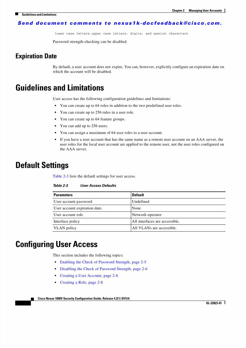
Default SettingsTable 2-3 lists the default settings for user access.
Configuring User AccessThis section includes the following topics:
• Enabling the Check of Password Strength, page 2-5
• Disabling the Check of Password Strength, page 2-6
• Creating a User Account, page 2-6
• Creating a Role, page 2-8
Table 2-3 User Access Defaults
Parameters Default
User account password Undefined
User account expiration date. None
User account role Network-operator
Interface policy All interfaces are accessible.
VLAN policy All VLANs are accessible.

8/13/2019 n1000v Security
http://slidepdf.com/reader/full/n1000v-security 29/234
S e n d d o c u m e n t c o m m e n t s t o n e x u s 1 k - d o c f e e d b a c k @ c i s c o . c o m .
2-5Cisco Nexus 1000V Security Configuration Guide, Release 4.2(1) SV1(4)
OL-22823-01
Chapter 2 Managing User AccountsConfiguring User Access
• Creating a Feature Group, page 2-10
• Configuring Interface Access, page 2-12
• Configuring VLAN Access, page 2-13
Enabling the Check of Password StrengthUse this procedure to enable the Cisco Nexus 1000V to check the strength of passwords to avoid creatingweak passwords for user accounts.
BEFORE YOU BEGIN
Before beginning this procedure, you must know or do the following.
• You are logged in to the CLI in EXEC mode.
• Checking password strength is enabled by default. This procedure can be used to enable it againshould it become disabled.
SUMMARY STEPS
1. config t
2 password strength-check
3 show password strength-check
4 copy running-config startup-config
DETAILED STEPS
Command Purpose
Step 1 config t
Example:n1000v# config tn1000v(config)#
Places you into the CLI Global Configurationmode.
Step 2 password strength-check
Example:n1000v(config)# password strength-check
Enables password-strength checking. The default isenabled.
You can disable the checking of password strengthby using the no form of this command.
Step 3 show password strength-check
Example:
n1000v# show password strength-checkPassword strength check enabledn1000v(config)#
(Optional) Displays the configuration for checkingpassword strength.
Step 4 copy running-config startup-config
Example:n1000v# copy running-config startup-config
(Optional) Saves the running configurationpersistently through reboots and restarts by copyingit to the startup configuration.

8/13/2019 n1000v Security
http://slidepdf.com/reader/full/n1000v-security 30/234
S e n d d o c u m e n t c o m m e n t s t o n e x u s 1 k - d o c f e e d b a c k @ c i s c o . c o m .
2-6Cisco Nexus 1000V Security Configuration Guide, Release 4.2(1) SV1(4)
OL-22823-01
Chapter 2 Managing User AccountsConfiguring User Access
Disabling the Check of Password StrengthUse this procedure to disable the check of password strength.
BEFORE YOU BEGIN
Before beginning this procedure, you must know or do the following.
• You are logged in to the CLI in EXEC mode.
• Checking password strength is enabled by default. This procedure can be used to disable it.
SUMMARY STEPS
1. config t
2 no password strength-check
3 show password strength-check
4 copy running-config startup-config
DETAILED STEPS
Creating a User AccountUse this procedure to create and configure a user account, defining access to the Cisco Nexus 1000V.
BEFORE YOU BEGIN
Before beginning this procedure, you must know or do the following.
• You are logged in to the CLI in EXEC mode.
Command Purpose
Step 1 config t
Example:n1000v# config tn1000v(config)#
Places you into the CLI Global Configurationmode.
Step 2 no password strength-check
Example:
n1000v(config)# no password strength-checkn1000v(config)#
Disables password-strength checking.
The default is enabled.
Step 3 show password strength-check
Example:n1000v# show password strength-checkPassword strength check not enabledn1000v(config)#
(Optional) Displays the configuration for checkingpassword strength.
Step 4 copy running-config startup-config
Example:n1000v# copy running-config startup-config
(Optional) Saves the running configurationpersistently through reboots and restarts by copyingit to the startup configuration.

8/13/2019 n1000v Security
http://slidepdf.com/reader/full/n1000v-security 31/234
S e n d d o c u m e n t c o m m e n t s t o n e x u s 1 k - d o c f e e d b a c k @ c i s c o . c o m .
2-7Cisco Nexus 1000V Security Configuration Guide, Release 4.2(1) SV1(4)
OL-22823-01
Chapter 2 Managing User AccountsConfiguring User Access
• You can add up to 256 user accounts.
• Changes to user accounts do not take effect until the user logs in and creates a new session.
• Do not use the following words in user accounts. These words are reserved for other purposes.
• You can add a user password as either clear text or encrypted.– Clear text passwords are encrypted before they are saved to the running configuration.
– Encrypted passwords are saved to the running configuration without further encryption.
• A user account can have up to 64 roles, but must have at least one role. For more information aboutroles, see the “Role” section on page 2-1 .
• If you do not specify a password, the user might not be able to log in.• For information about using SSH public keys instead of passwords, see the “Configuring a User
Account with a Public Key” section on page 7-5 .
SUMMARY STEPS
1. config t
2 show role
3 username user-name [password [0 | 5] password ] [expire date ] [role role-name ]
4 show user-account user-name
5 copy running-config startup-config
DETAILED STEPS
adm
bindaemon
ftp
ftpuser
games
gdm
gopher haltlp
mailnull
man
mtsuser
newsnobody
nscd
operator
rpc
rpcuser
shutdownsync
sys
uucp
xfs
Command Purpose
Step 1 config t
Example:n1000v# config tn1000v(config)#
Places you into the CLI Global Configuration mode.
Step 2 show role
Example:n1000v(config)# show role
(Optional) Displays the available roles that can beassigned to users.
You can create a new user role with the “Creating aRole” procedure on page 2-8 )

8/13/2019 n1000v Security
http://slidepdf.com/reader/full/n1000v-security 32/234
S e n d d o c u m e n t c o m m e n t s t o n e x u s 1 k - d o c f e e d b a c k @ c i s c o . c o m .
2-8Cisco Nexus 1000V Security Configuration Guide, Release 4.2(1) SV1(4)
OL-22823-01
Chapter 2 Managing User AccountsConfiguring User Access
Creating a RoleUse this procedure to create a role defining a set of specific actions that are permitted or denied. Thisrole will be assigned to users whose access requirements match the actions defined.
BEFORE YOU BEGIN
Before beginning this procedure, you must know or do the following:
• You are logged in to the CLI in EXEC mode.
• You can configure up to 64 user roles.
Step 3 username name [ password [ 0 | 5] pass word ][expire date] [role role-name ]
Example:n1000v(config)# username NewUser password4Ty18Rnt
Creates a user account.
• name : A case-sensitive, alphanumeric characterstring of up to 28 characters in length.
• password : The default password is undefined. – 0 = (the default) Specifies that the password
you are entering is in clear text. The CiscoNexus 1000V encrypts the clear textpassword before saving it in the runningconfiguration.
In the example shown, the password4Ty18Rnt is encrypted in your runningconfiguration in password 5 format.
– 5 = Specifies that the password you areentering is already in encrypted format. TheCisco Nexus 1000V does not encrypt thepassword before saving it in the runningconfiguration.
User passwords are not displayed in theconfiguration files.
• expire date : YYYY-MM-DD.The default is no expiration date.
• role : You must assign at least one role. You canassign up to 64 roles. The default role isnetwork-operator .
Step 4 show user-account username
Example :n1000v(config)# show user-account NewUseruser:NewUser this user account has no expiry date roles:network-operator network-adminn1000v(config)#
Displays the new user account configuration.
Step 5 copy running-config startup-config
Example:n1000v# copy running-config startup-config
(Optional) Saves the running configurationpersistently through reboots and restarts by copyingit to the startup configuration.
Command Purpose
8/13/2019 n1000v Security
http://slidepdf.com/reader/full/n1000v-security 33/234
S e n d d o c u m e n t c o m m e n t s t o n e x u s 1 k - d o c f e e d b a c k @ c i s c o . c o m .
2-9Cisco Nexus 1000V Security Configuration Guide, Release 4.2(1) SV1(4)
OL-22823-01
Chapter 2 Managing User AccountsConfiguring User Access
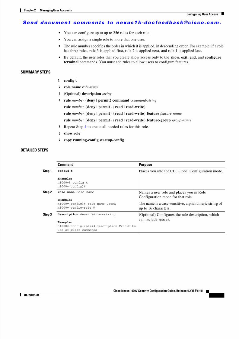
• You can configure up to up to 256 rules for each role.
• You can assign a single role to more that one user.
• The rule number specifies the order in which it is applied, in descending order. For example, if a rolehas three rules, rule 3 is applied first, rule 2 is applied next, and rule 1 is applied last.
• By default, the user roles that you create allow access only to the show , exit , end , and configureterminal commands. You must add rules to allow users to configure features.
SUMMARY STEPS
1. config t
2 role name role-name
3 (Optional) description string
4 rule number {deny | permit} command command-string
rule number {deny | permit } { read | read-write }
rule number {deny | permit } { read | read-write } feature feature-name
rule number {deny | permit } { read | read-write } feature-group group-name
5 Repeat Step 4 to create all needed rules for this role.
6 show role
7 copy running-config startup-config
DETAILED STEPS
Command Purpose
Step 1 config t
Example:n1000v# config tn1000v(config)#
Places you into the CLI Global Configuration mode.
Step 2 role name role-name
Example:n1000v(config)# role name UserAn1000v(config-role)#
Names a user role and places you in RoleConfiguration mode for that role.
The name is a case-sensitive, alphanumeric string ofup to 16 characters.
Step 3 description description-string
Example:n1000v(config-role)# description Prohibitsuse of clear commands
(Optional) Configures the role description, whichcan include spaces.
8/13/2019 n1000v Security
http://slidepdf.com/reader/full/n1000v-security 34/234
S e n d d o c u m e n t c o m m e n t s t o n e x u s 1 k - d o c f e e d b a c k @ c i s c o . c o m .
2-10Cisco Nexus 1000V Security Configuration Guide, Release 4.2(1) SV1(4)
OL-22823-01
Chapter 2 Managing User AccountsConfiguring User Access
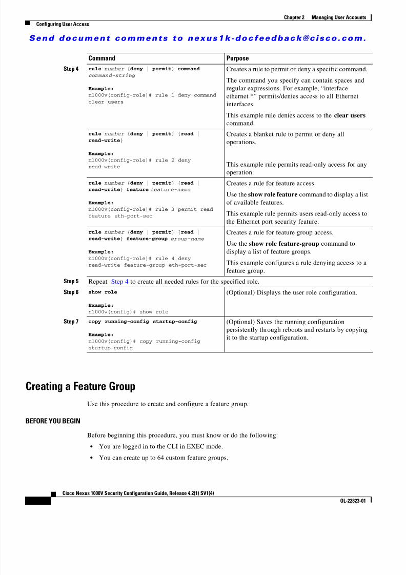
Creating a Feature Group
Use this procedure to create and configure a feature group.
BEFORE YOU BEGIN
Before beginning this procedure, you must know or do the following:
• You are logged in to the CLI in EXEC mode.
• You can create up to 64 custom feature groups.
Step 4 rule number {deny | permit } command command-string
Example:n1000v(config-role)# rule 1 deny commandclear users
Creates a rule to permit or deny a specific command.
The command you specify can contain spaces andregular expressions. For example, “interfaceethernet *” permits/denies access to all Ethernetinterfaces.
This example rule denies access to the clear users command.
rule number {deny | permit } { read |read-write }
Example:n1000v(config-role)# rule 2 denyread-write
Creates a blanket rule to permit or deny alloperations.
This example rule permits read-only access for anyoperation.
rule number {deny | permit } { read |read-write } feature feature-name
Example:n1000v(config-role)# rule 3 permit readfeature eth-port-sec
Creates a rule for feature access.
Use the show role feature command to display a listof available features.This example rule permits users read-only access tothe Ethernet port security feature.
rule number {deny | permit } { read |read-write } feature-group group-name
Example:n1000v(config-role)# rule 4 denyread-write feature-group eth-port-sec
Creates a rule for feature group access.
Use the show role feature-group command todisplay a list of feature groups.
This example configures a rule denying access to afeature group.
Step 5 Repeat Step 4 to create all needed rules for the specified role.
Step 6 show role
Example:n1000v(config)# show role
(Optional) Displays the user role configuration.
Step 7 copy running-config startup-config
Example:n1000v(config)# copy running-configstartup-config
(Optional) Saves the running configurationpersistently through reboots and restarts by copyingit to the startup configuration.
Command Purpose

8/13/2019 n1000v Security
http://slidepdf.com/reader/full/n1000v-security 35/234
S e n d d o c u m e n t c o m m e n t s t o n e x u s 1 k - d o c f e e d b a c k @ c i s c o . c o m .
2-11Cisco Nexus 1000V Security Configuration Guide, Release 4.2(1) SV1(4)
OL-22823-01
Chapter 2 Managing User AccountsConfiguring User Access
SUMMARY STEPS
1. config t
2 role feature-group name group-name
3 show role feature
4 feature feature-name
5 Repeat 4 for all features to be added to the feature group.
6 show role feature-group
7 copy running-config startup-config
DETAILED STEPS
Command Purpose
Step 1 config t
Example:n1000v# config tn1000v(config)#
Places you into the CLI Global Configuration mode.
Step 2 role feature-group name group-name
Example:n1000v(config)# role feature-group nameGroupAn1000v(config-role-featuregrp)#
Places you into the Role Feature GroupConfiguration mode for the named group.
• group-name : A case-sensitive, alphanumericstring of up to 32 characters in length.
Step 3 show role feature
Example:n1000v(config-role-featuregrp)# show rolefeature
feature: aaafeature: access-listfeature: cdpfeature: install. . .n1000v(config-role-featuregrp)#
Displays a list of available features for use indefining the feature group.
Step 4 feature feature-name
Example:n1000v(config-role-featuregrp)# featuresyslogn1000v(config-role-featuregrp)#
Adds a feature to the feature group.
Step 5 Repeat Step 6 for all features to be added to the feature group.

8/13/2019 n1000v Security
http://slidepdf.com/reader/full/n1000v-security 36/234
S e n d d o c u m e n t c o m m e n t s t o n e x u s 1 k - d o c f e e d b a c k @ c i s c o . c o m .
2-12Cisco Nexus 1000V Security Configuration Guide, Release 4.2(1) SV1(4)
OL-22823-01
Chapter 2 Managing User AccountsConfiguring User Access
Configuring Interface AccessUse this procedure to configure interface access for a specific role.
BEFORE YOU BEGIN
Before beginning this procedure, you must know or do the following:
• You are logged in to the CLI in EXEC mode.
• You have already created one or more user roles using the “Creating a Role” procedure on page 2-8 .In this procedure, you will be modifying a role you have already created.
• By default, a role allows access to all interfaces. In this procedure you will, first, deny access to allinterfaces and then permit access to selected interfaces.
SUMMARY STEPS
1. config t
2 role name role-name
3 interface policy deny
4 permit interface interface-list
5 show role
6 copy running-config startup-config
Step 6 show role feature-group
Example:n1000v(config-role-featuregrp)# show rolefeature-groupfeature group: GroupAfeature: syslogfeature: snmpfeature: pingn1000v(config-role-featuregrp)#
(Optional) Displays the feature group configuration.
Step 7 copy running-config startup-config
Example:n1000v(config-role-featuregrp)# copyrunning-config startup-config
(Optional) Saves the running configurationpersistently through reboots and restarts by copyingit to the startup configuration.
Command Purpose
8/13/2019 n1000v Security
http://slidepdf.com/reader/full/n1000v-security 37/234
S e n d d o c u m e n t c o m m e n t s t o n e x u s 1 k - d o c f e e d b a c k @ c i s c o . c o m .
2-13Cisco Nexus 1000V Security Configuration Guide, Release 4.2(1) SV1(4)
OL-22823-01
Chapter 2 Managing User AccountsConfiguring User Access
DETAILED STEPS
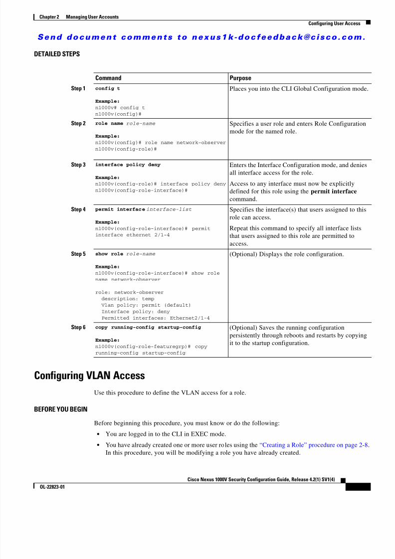
Configuring VLAN Access
Use this procedure to define the VLAN access for a role.
BEFORE YOU BEGIN
Before beginning this procedure, you must know or do the following:
• You are logged in to the CLI in EXEC mode.
• You have already created one or more user roles using the “Creating a Role” procedure on page 2-8 .In this procedure, you will be modifying a role you have already created.
Command Purpose
Step 1 config t
Example:n1000v# config tn1000v(config)#
Places you into the CLI Global Configuration mode.
Step 2 role name role-name
Example:n1000v(config)# role name network-observern1000v(config-role)#
Specifies a user role and enters Role Configurationmode for the named role.
Step 3 interface policy deny
Example:n1000v(config-role)# interface policy denyn1000v(config-role-interface)#
Enters the Interface Configuration mode, and deniesall interface access for the role.
Access to any interface must now be explicitlydefined for this role using the permit interface command.
Step 4 permit interface interface-list
Example:n1000v(config-role-interface)# permitinterface ethernet 2/1-4
Specifies the interface(s) that users assigned to thisrole can access.
Repeat this command to specify all interface liststhat users assigned to this role are permitted toaccess.
Step 5 show role role-name
Example:n1000v(config-role-interface)# show rolename network-observer
role: network-observer description: temp Vlan policy: permit (default) Interface policy: deny Permitted interfaces: Ethernet2/1-4
(Optional) Displays the role configuration.
Step 6 copy running-config startup-config
Example:n1000v(config-role-featuregrp)# copyrunning-config startup-config
(Optional) Saves the running configurationpersistently through reboots and restarts by copyingit to the startup configuration.

8/13/2019 n1000v Security
http://slidepdf.com/reader/full/n1000v-security 38/234
S e n d d o c u m e n t c o m m e n t s t o n e x u s 1 k - d o c f e e d b a c k @ c i s c o . c o m .
2-14Cisco Nexus 1000V Security Configuration Guide, Release 4.2(1) SV1(4)
OL-22823-01
Chapter 2 Managing User AccountsConfiguring User Access
• By default, access is allowed to all VLANs. In this procedure you will, first, deny access to allVLANs and then permit access to selected VLANs.
SUMMARY STEPS
1. config t
2 role name role-name
3 vlan policy deny
4 permit vlan vlan-range
5 exit
6 show role
7 copy running-config startup-config
DETAILED STEPS
Command PurposeStep 1 config t
Example:n1000v# config tn1000v(config)#
Places you into the CLI Global Configuration mode.
Step 2 role name role-name
Example:n1000v(config)# role name network-observern1000v(config-role)#
Specifies a user role and enters role configurationmode.
Step 3 vlan policy deny
Example:n1000v(config-role)# vlan policy denyn1000v(config-role-vlan)#
Enters the VLAN Configuration mode, and deniesall VLAN access for the role.
Access to any VLAN must now be explicitly definedfor this role using the permit vlan command.
Step 4 permit vlan vlan-list
Example:n1000v(config-role-vlan)# permit vlan 1-4
Specifies the VLAN(s) that users assigned to thisrole can access.
Repeat this command to specify all VLANs thatusers assigned to this role are permitted to access.

8/13/2019 n1000v Security
http://slidepdf.com/reader/full/n1000v-security 39/234
S e n d d o c u m e n t c o m m e n t s t o n e x u s 1 k - d o c f e e d b a c k @ c i s c o . c o m .
2-15Cisco Nexus 1000V Security Configuration Guide, Release 4.2(1) SV1(4)
OL-22823-01
Chapter 2 Managing User AccountsVerifying the User Access Configuration
Verifying the User Access ConfigurationTo display user account and RBAC configuration information, perform one of the following tasks:
Example ConfigurationThe following example shows how to configure a role:
role name UserA rule 3 permit read feature snmp rule 2 permit read feature dot1x
rule 1 deny command clear *
The following example shows how to configure a feature group:
role feature-group name Security-features feature radius feature tacacs feature dot1x feature aaa feature snmp feature acl feature access-list
Step 5 show role role-name
Example:n1000v(config-role)# show rolenetwork-observer
role: network-observer description: temp Vlan policy: deny Permitted vlans: vlan 1-4 Interface policy: deny Permitted interfaces: Ethernet2/1-4
(Optional) Displays the role configuration.
Step 6 copy running-config startup-config
Example:n1000v(config-role)# copy running-configstartup-config
(Optional) Saves the running configurationpersistently through reboots and restarts by copyingit to the startup configuration.
Command Purpose
Command Purpose
show role Displays the available user roles and their rules.
show role feature Displays a list of available features.
show role feature-group Displays a list of available feature groups.
show startup-config security Displays the user account configuration in the startupconfiguration.
show running-config security [all ] Displays the user account configuration in the runningconfiguration. The all keyword displays the defaultvalues for the user accounts.
show user-account Displays user account information.
8/13/2019 n1000v Security
http://slidepdf.com/reader/full/n1000v-security 40/234
S e n d d o c u m e n t c o m m e n t s t o n e x u s 1 k - d o c f e e d b a c k @ c i s c o . c o m .
2-16Cisco Nexus 1000V Security Configuration Guide, Release 4.2(1) SV1(4)
OL-22823-01
Chapter 2 Managing User AccountsAdditional References
Additional ReferencesFor additional information related to implementing RBAC, see the following sections: • Related Documents, page 2-16
• Standards, page 2-16
• MIBs, page 2-16
Related Documents
Standards
MIBs
Feature History for User AccountsThis section provides the user accounts release history.
Related Topic Document Title
User access commands Cisco Nexus 1000V Command Reference, Release 4.2(1)SV1(4)
Managing users on the switch Cisco Nexus 1000V Getting Started Guide, Release 4.2(1)SV1(4)
Standards Title
No new or modified standards are supported by thisfeature, and support for existing standards has not beenmodified by this feature.
—
MIBs MIBs Link
• CISCO-COMMON-MGMT-MIB To locate and download MIBs, go to the following URL:
http://www.cisco.com/public/sw-center/netmgmt/cmtk/mibs.shtml
Feature Name Releases Feature InformationUser Accounts 4.0(4)SV1(1) This feature was introduced.

8/13/2019 n1000v Security
http://slidepdf.com/reader/full/n1000v-security 41/234
C H A P T E R
S e n d d o c u m e n t c o m m e n t s t o n e x u s 1 k - d o c f e e d b a c k @ c i s c o . c o m .
3-1Cisco Nexus 1000V Security Configuration Guide, Release 4.2(1) SV1(4)
OL-22823-01
3Configuring VSD
This chapter describes how to configure VSD and includes the following topics:
• Information About Virtual Service Domain, page 3-1
• Guidelines and Limitations, page 3-3
• Default Settings, page 3-3
• Configuring VSD, page 3-4
• Verifying the Configuration, page 3-8
• Configuration Example, page 3-10
• Additional References, page 3-10
• Feature History, page 3-11
Information About Virtual Service DomainA virtual service domain (VSD) allows you to classify and separate traffic for network services, such asfirewalls, traffic monitoring, and those in support of compliance goals such as Sarbanes Oxley.
Service Virtual MachineA service VM (SVM) provides the specialized service like firewall, deep packet inspection (applicationaware networking), or monitoring. Each Service VM has three virtual interfaces:
Interface Description
Management A regular interface that manages the SVM
Should have Layer 2 or Layer 3 connectivity, depending on its use.
Incoming Guards the traffic coming into the VSDAny packet coming into the VSD must go through this interface.
Outgoing Guards the traffic going out of the VSD.
Any packet that originates in the VSD and goes out must go through theSVM and out through the outgoing interface.

8/13/2019 n1000v Security
http://slidepdf.com/reader/full/n1000v-security 42/234
S e n d d o c u m e n t c o m m e n t s t o n e x u s 1 k - d o c f e e d b a c k @ c i s c o . c o m .
3-2Cisco Nexus 1000V Security Configuration Guide, Release 4.2(1) SV1(4)
OL-22823-01
Chapter 3 Configuring VSDInformation About Virtual Service Domain
There is no source MAC learning on these interfaces. Each SVM creates a secure VSD. Interfaces withinthe VSD are shielded by the SVM.
Port ProfilesA VSD is the collection of interfaces that are guarded by the SVM providing the security service. Anytraffic coming into the VSD or going out of the VSD has to go through the SVM.
Traffic that both originates and terminates within the same VSD need not be routed through the SVM asit is considered to be safe.
A VSD is formed by creating the following port profiles:
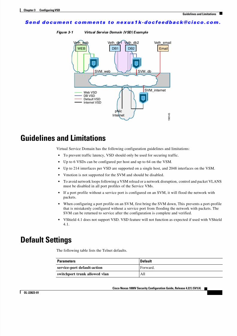
In Figure 3-1 , a single VEM takes the place of vswitches; the SVMs define the following VSDs;
Port Profile Description
Inside Traffic originating from a VSD member goes into the service VM (SVM)through the inside port and comes out of the outside port before it is forwardedto its destination.
Outside Traffic destined for a VSD member goes into the SVM through the outside portand comes out of the inside port before it is forwarded to its destination.
Member Location for individual inside VMs.
VSD SVM (guard) Inside Port Profile Outside Port ProfileMember PortProfile(s)
DB VSD SVM_db SVM_db_inside SVM_db_outside vEth_db1
vEth_db2
Web VSD SVM_web SVM_web_inside SVM_web_outside vEth_web
Internet VSD SVM_Internet SVM_internet_inside SVM_internet_outsideDefault SVM VSD vEth Email
8/13/2019 n1000v Security
http://slidepdf.com/reader/full/n1000v-security 43/234
S e n d d o c u m e n t c o m m e n t s t o n e x u s 1 k - d o c f e e d b a c k @ c i s c o . c o m .
3-3Cisco Nexus 1000V Security Configuration Guide, Release 4.2(1) SV1(4)
OL-22823-01
Chapter 3 Configuring VSDGuidelines and Limitations
Figure 3-1 Virtual Service Domain (VSD) Example
Guidelines and LimitationsVirtual Service Domain has the following configuration guidelines and limitations:
• To prevent traffic latency, VSD should only be used for securing traffic.
• Up to 6 VSDs can be configured per host and up to 64 on the VSM.
• Up to 214 interfaces per VSD are supported on a single host, and 2048 interfaces on the VSM.
• Vmotion is not supported for the SVM and should be disabled. • To avoid network loops following a VSM reload or a network disruption, control and packet VLANS
must be disabled in all port profiles of the Service VMs.
• If a port profile without a service port is configured on an SVM, it will flood the network withpackets.
• When configuring a port profile on an SVM, first bring the SVM down, This prevents a port-profilethat is mistakenly configured without a service port from flooding the network with packets. TheSVM can be returned to service after the configuration is complete and verified.
• VShield 4.1 does not support VSD. VSD feature will not function as expected if used with VShield4.1.
Default SettingsThe following table lists the Telnet defaults.
WEB DB1 DB2 Email
pNicInternet
SVM_web SVM_db
SVM_internet
Veth_web Veth_db1 Veth_db2 Veth_email
Web VSDDB VSDDefault VSDInternet VSD
1 9 6
1 4 5
Parameters Default
service-port default-action Forward.
switchport trunk allowed vlan All

8/13/2019 n1000v Security
http://slidepdf.com/reader/full/n1000v-security 44/234
S e n d d o c u m e n t c o m m e n t s t o n e x u s 1 k - d o c f e e d b a c k @ c i s c o . c o m .
3-4Cisco Nexus 1000V Security Configuration Guide, Release 4.2(1) SV1(4)
OL-22823-01
Chapter 3 Configuring VSDConfiguring VSD
Configuring VSDThis section includes the following procedures:
• Configuring an Inside or Outside VSD Port Profile, page 3-4
• Configuring a Member VSD Port Profile, page 3-7
Configuring an Inside or Outside VSD Port ProfileUse this procedure to configure the port-profiles that define the connections going into and out of theSVM.
BEFORE YOU BEGIN
Before beginning this procedure, you must know or do the following:
• You are logged in to the CLI in EXEC mode.
• You have taken the SVM out of service to prevent any configuration errors from flooding thenetwork. Once the configuration is complete and verified, you can bring the SVM back into service.
• If you do not configure a service-port, the SVM will come up as a regular VM, flooding the networkwith packets.
• Selected VLAN filtering is not supported in this configuration. The default should be used instead,which allows all VLANs on the port.
SUMMARY STEPS
1. config t
2. port-profile name
3. switchport mode trunk4. switchport trunk allowed vlan vlanID
5. virtual-service-domain name
6. no shut
7. vmware port-group pg-name
8. service-port {inside | outside } [default-action {drop | forward }]
9. state enabled
10. show virtual-service-domain name
11. copy running-config startup-config
8/13/2019 n1000v Security
http://slidepdf.com/reader/full/n1000v-security 45/234
S e n d d o c u m e n t c o m m e n t s t o n e x u s 1 k - d o c f e e d b a c k @ c i s c o . c o m .
3-5Cisco Nexus 1000V Security Configuration Guide, Release 4.2(1) SV1(4)
OL-22823-01
Chapter 3 Configuring VSDConfiguring VSD
DETAILED STEPS
Command Purpose
Step 1 config t
Example:n1000v# config tn1000v(config)#
Places you in the CLI Global Configuration mode.
Step 2 port-profile name
Example:n1000v(config)# port-profile
webserver-insiden1000v(config-port-profile)#
Creates a port profile and places you into Port ProfileConfiguration mode for the named port profile.
The port profile name can be up to 80 characters andmust be unique for each port profile on the CiscoNexus 1000V.
Step 3 switchport mode trunk
Example:n1000v(config-port-profile)# switchport
mode trunkn1000v(config-port-profile)#
Designates that the interfaces are switch trunk ports.
Step 4 switchport trunk allowed vlan vlanID
Example:n1000v(config-port-profile)# switchporttrunk allowed vlan alln1000v(config-port-profile)#
Allows all VLANs on the port.
Step 5 virtual-service-domain name
Example:n1000v(config-port-profile)#virtual-service-domain vsd1-webservern1000v(config-port-profile)#
Adds a VSD name to this port profile.
Step 6 no shutdownExample:n1000v(config-port-prof)# no shutdownn1000v(config-port-prof)#
Administratively enables all ports in the profile.
Step 7 vmware port-group pg-name
Example :n1000v(config-port-prof)# vmwareport-group webservers-inside-protectedn1000v(config-port-prof)#
Designates the port-profile as a VMware port-group.
The port profile is mapped to a VMware port group ofthe same name. When a vCenter Server connection isestablished, the port group created in Cisco Nexus1000V is then distributed to the virtual switch on thevCenter Server.
name : Port group name. If you do not specify apg-name, then the port group name will be the same asthe port profile name. If you want to map the portprofile to a different port group name, use the pg-nameoption followed by the alternate name.

8/13/2019 n1000v Security
http://slidepdf.com/reader/full/n1000v-security 46/234
S e n d d o c u m e n t c o m m e n t s t o n e x u s 1 k - d o c f e e d b a c k @ c i s c o . c o m .
3-6Cisco Nexus 1000V Security Configuration Guide, Release 4.2(1) SV1(4)
OL-22823-01
Chapter 3 Configuring VSDConfiguring VSD
Step 8 service-port {inside | outside }[default-action {drop | forward }]
Configures the interface as either inside or outside anddesignates (default-action) whether packets should beforwarded or dropped if the service port is down.
If you do not specify a default-action, then theforward setting is used by default.
Caution If you do not configure a service-port, theSVM will come up as a regular VM,flooding the network with packets.
Example:n1000v(config-port-prof)# service-portinside default-action forwardn1000v(config-port-prof)#
This example configures an inside VSD that forwardspackets if the service port is down.
Example:n1000v(config-port-prof)# service-portoutside default-action forwardn1000v(config-port-prof)#
This example configures an outside VSD that forwardspackets if the service port is down.
Step 9 state enabled
Example:n1000v(config-port-prof)# state enabledn1000v(config-port-prof)#
Enables the VSD port profile.
The configuration for this port profile is applied to theassigned ports, and the port group is created in theVMware vSwitch on the vCenter Server.
Step 10 show virtual-service-domain name
Example:n1000v(config-port-prof)# showvirtual-service-domain vsd1-webserverDefault Action: forward___________________________Interface Type___________________________
Vethernet1 Member Vethernet2 Member Vethernet3 Member Vethernet7 Inside Vethernet8 Outside
n1000v(config-port-prof)#
(Optional) Displays the configuration for this VSDport profile. Use this to verify that the port-profile wasconfigured as expected.
Step 11 copy running-config startup-config
Example:n1000v(config-port-prof)# copyrunning-config startup-config[#######################################
#] 100%n1000v(config-port-prof)#
(Optional) Saves the running configurationpersistently through reboots and restarts by copying itto the startup configuration.
Command Purpose
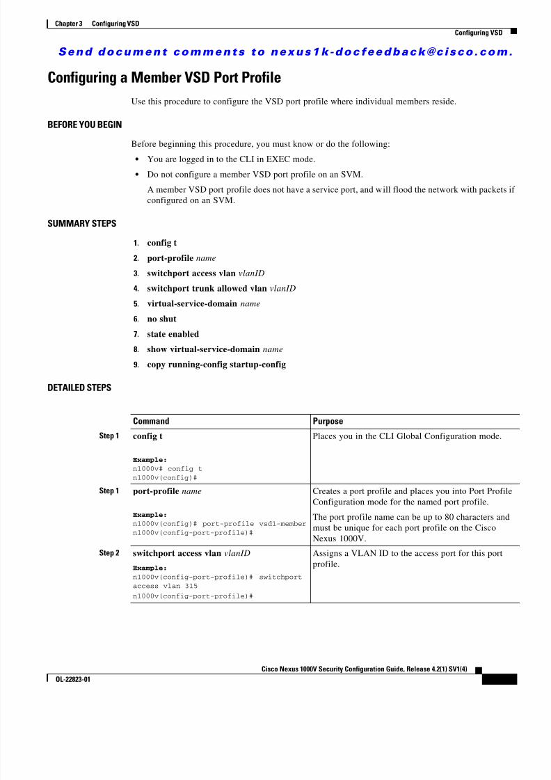
8/13/2019 n1000v Security
http://slidepdf.com/reader/full/n1000v-security 47/234
S e n d d o c u m e n t c o m m e n t s t o n e x u s 1 k - d o c f e e d b a c k @ c i s c o . c o m .
3-7Cisco Nexus 1000V Security Configuration Guide, Release 4.2(1) SV1(4)
OL-22823-01
Chapter 3 Configuring VSDConfiguring VSD
Configuring a Member VSD Port ProfileUse this procedure to configure the VSD port profile where individual members reside.
BEFORE YOU BEGIN
Before beginning this procedure, you must know or do the following:
• You are logged in to the CLI in EXEC mode.
• Do not configure a member VSD port profile on an SVM.
A member VSD port profile does not have a service port, and will flood the network with packets ifconfigured on an SVM.
SUMMARY STEPS
1. config t
2. port-profile name
3. switchport access vlan vlanID4. switchport trunk allowed vlan vlanID
5. virtual-service-domain name
6. no shut
7. state enabled
8. show virtual-service-domain name
9. copy running-config startup-config
DETAILED STEPS
Command Purpose
Step 1 config t
Example:n1000v# config tn1000v(config)#
Places you in the CLI Global Configuration mode.
Step 1 port-profile name
Example:n1000v(config)# port-profile vsd1-membern1000v(config-port-profile)#
Creates a port profile and places you into Port ProfileConfiguration mode for the named port profile.
The port profile name can be up to 80 characters andmust be unique for each port profile on the CiscoNexus 1000V.
Step 2 switchport access vlan vlanID
Example:n1000v(config-port-profile)# switchportaccess vlan 315n1000v(config-port-profile)#
Assigns a VLAN ID to the access port for this portprofile.

8/13/2019 n1000v Security
http://slidepdf.com/reader/full/n1000v-security 48/234
S e n d d o c u m e n t c o m m e n t s t o n e x u s 1 k - d o c f e e d b a c k @ c i s c o . c o m .
3-8Cisco Nexus 1000V Security Configuration Guide, Release 4.2(1) SV1(4)
OL-22823-01
Chapter 3 Configuring VSDVerifying the Configuration
Verifying the ConfigurationTo display the VSD configuration, use the following commands:
Step 3 virtual-service-domain name
Example:n1000v(config-port-profile)#virtual-service-domain vsd1-webserver
n1000v(config-port-profile)#
Assigns a VSD name to this port profile.
Step 4 no shutdown
Example:n1000v(config-port-prof)# no shutdownn1000v(config-port-prof)#
Administratively enables all ports in the profile.
Step 5 state enabled
Example:n1000v(config-port-prof)# state enabledn1000v(config-port-prof)#
Enables the VSD port profile.
The configuration for this port profile is applied to theassigned ports, and the port group is created in theVMware vSwitch on the vCenter Server.
Step 6 show virtual-service-domain name
Example:
n1000v(config-port-prof)# showvirtual-service-domain vsd1-webserverDefault Action: forward___________________________Interface Type___________________________
Vethernet1 Member Vethernet2 Member Vethernet3 Member Vethernet6 Member Vethernet7 Inside Vethernet8 Outside
n1000v(config-port-prof)#
(Optional) Displays the configuration for this VSDport profile. Use this to verify that the port-profile wasconfigured as expected.
Step 7 copy running-config startup-config
Example:n1000v(config-port-prof)# copyrunning-config startup-config[########################################] 100%n1000v(config-port-prof)#
(Optional) Saves the running configuration
persistently through reboots and restarts by copying itto the startup configuration.
Command Purpose
Command Purposeshow virtual-service-domain name vsd-name Displays a specific VSD configuration.
See Example 3-1 on page 3-9 .
show virtual-service-domain brief Displays a summary of all VSD configurations.
See Example 3-2 on page 3-9 .

8/13/2019 n1000v Security
http://slidepdf.com/reader/full/n1000v-security 49/234
S e n d d o c u m e n t c o m m e n t s t o n e x u s 1 k - d o c f e e d b a c k @ c i s c o . c o m .
3-9Cisco Nexus 1000V Security Configuration Guide, Release 4.2(1) SV1(4)
OL-22823-01
Chapter 3 Configuring VSDVerifying the Configuration
For detailed information about command output for these commands, see the Cisco Nexus 1000VCommand Reference, Release 4.2(1)SV1(4) .
Example 3-1 show virtual-service-domain name vsd_name
n1000v## show virtual-service-domain name vsd1Default Action: drop___________________________Interface Type___________________________
Vethernet1 Member Vethernet2 Member Vethernet3 Member Vethernet6 Member Vethernet7 Inside Vethernet8 Outside
n1000v#
Example 3-2 show virtual-service-domain brief
n1000v# show virtual-service-domain briefName vsd-id default action in-ports ou t-ports mem-ports Modules with
VSD Enabledzone 1 forward 1 1 2 4n1000v#
Example 3-3 show virtual-service-domain interface
n1000v# sho virtual-service-domain interface_ _ _ _ _ _ _ _ _ _ _ _ _ _ _ _ _ _ _ _ _ _ _ _ _ _ _ _Name Interface Type Status
_ _ _ _ _ _ _ _ _ _ _ _ _ _ _ _ _ _ _ _ _ _ _ _ _ _ _ _vsd1 Vethernet1 Member Activevsd1 Vethernet2 Member Activevsd1 Vethernet3 Member Activevsd1 Vethernet6 Member Activevsd1 Vethernet7 Inside Activevsd1 Vethernet8 Outside Activevsd2 Vethernet9 Inside Activevsd2 Vethernet10 Outside Active
show virtual-service-domain interface Displays the interface configuration for all VSDs.
See Example 3-3 on page 3-9 .
module vem module_number execute vemcmd
show vsd
Displays the VEM VSD configuration by sending
the command to the VEM from the remote CiscoNexus 1000V.
See Example 3-4 on page 3-10 .
module vem module_number execute vemcmdshow vsd ports
Displays the VEM VSD ports configuration bysending the command to the VEM from theremote Cisco Nexus 1000V.
See Example 3-5 on page 3-10 .
Command Purpose

8/13/2019 n1000v Security
http://slidepdf.com/reader/full/n1000v-security 50/234
S e n d d o c u m e n t c o m m e n t s t o n e x u s 1 k - d o c f e e d b a c k @ c i s c o . c o m .
3-10Cisco Nexus 1000V Security Configuration Guide, Release 4.2(1) SV1(4)
OL-22823-01
Chapter 3 Configuring VSDConfiguration Example
Example 3-4 module module_number execute vemcmd show vsd
n1000v# module vem 4 execute vemcmd show vsd ID Def_Act ILTL OLTL NMLTL State Member LTLs 1 FRWD 51 50 1 ENA 49 n1000v#
Example 3-5 module module_number execute vemcmd show vsd ports
n1000v# module vem 4 execute vemcmd show vsd ports LTL IfIndex VSD_ID VSD_PORT_TYPE 49 1c000010 1 REGULAR 50 1c000040 1 OUTSIDE 51 1c000030 1 INSIDE n1000v#
Configuration ExampleThe following example shows how to configure VSD.
port-profile vsd1_member vmware port-group switchport access vlan 315 virtual-service-domain vsd1 no shutdown state enabledport-profile svm_vsd1_in vmware port-group switchport mode trunk switchport trunk allowed vlan 310-319 virtual-service-domain vsd1 service-port inside default-action drop no shutdown state enabledport-profile svm_vsd1_out vmware port-group switchport mode trunk switchport trunk allowed vlan 310-319 virtual-service-domain vsd1 service-port outside default-action drop no shutdown
Additional ReferencesFor additional information related to VSD configuration, see the following:
• Related Documents, page 3-11
• Standards, page 3-11

8/13/2019 n1000v Security
http://slidepdf.com/reader/full/n1000v-security 51/234
S e n d d o c u m e n t c o m m e n t s t o n e x u s 1 k - d o c f e e d b a c k @ c i s c o . c o m .
3-11Cisco Nexus 1000V Security Configuration Guide, Release 4.2(1) SV1(4)
OL-22823-01
Chapter 3 Configuring VSDFeature History
Related Documents
Standards
Feature HistoryThis section provides the VSD release history.
Related Topic Document Title
Port Profiles Cisco Nexus 1000V Port Profile Configuration Guide, Release 4.2(1)SV1(4)
CLI Cisco Nexus 1000V Getting Started Guide, Release 4.2(1)SV1(4)Cisco Nexus 1000V Command Reference, Release 4.2(1)SV1(4)
Standards Title
No new or modified standards are supported by thisfeature, and support for existing standards has not beenmodified by this feature.
—
Feature Name Releases Feature Information
VSD 4.0(4)SV1(2) This feature was introduced.

8/13/2019 n1000v Security
http://slidepdf.com/reader/full/n1000v-security 52/234
S e n d d o c u m e n t c o m m e n t s t o n e x u s 1 k - d o c f e e d b a c k @ c i s c o . c o m .
3-12Cisco Nexus 1000V Security Configuration Guide, Release 4.2(1) SV1(4)
OL-22823-01
Chapter 3 Configuring VSDFeature History
8/13/2019 n1000v Security
http://slidepdf.com/reader/full/n1000v-security 53/234
C H A P T E R
S e n d d o c u m e n t c o m m e n t s t o n e x u s 1 k - d o c f e e d b a c k @ c i s c o . c o m .
4-1Cisco Nexus 1000V Security Configuration Guide, Release 4.2(1) SV1(4)
OL-22823-01
4Configuring AAA
This chapter describes how to configure authentication, authorization, and accounting (AAA) andincludes the following sections:
• Information About AAA, page 4-1
• Prerequisites for AAA, page 4-4
• AAA Guidelines and Limitations, page 4-4
• Default Settings, page 4-4
• Configuring AAA, page 4-4
• Verifying AAA Configuration, page 4-8
• Example AAA Configuration, page 4-9
• Additional References, page 4-9
• Feature History for AAA, page 4-10
Information About AAAThis section includes the following topics:
• AAA Security Services, page 4-1
• AAA Server Groups, page 4-4
AAA Security ServicesBased on a user ID and password combination, AAA is used to authenticate and authorize users. A keysecures communication with AAA servers.
In many circumstances, AAA uses protocols such as RADIUS or TACACS+, to administer its securityfunctions. If your router or access server is acting as a network access server, AAA is the means throughwhich you establish communication between your network access server and your RADIUS orTACACS+, security server.
Although AAA is the primary (and recommended) method for access control, additional features forsimple access control are available outside the scope of AAA, such as local username authentication,line password authentication, and enable password authentication. However, these features do notprovide the same degree of access control that is possible by using AAA.
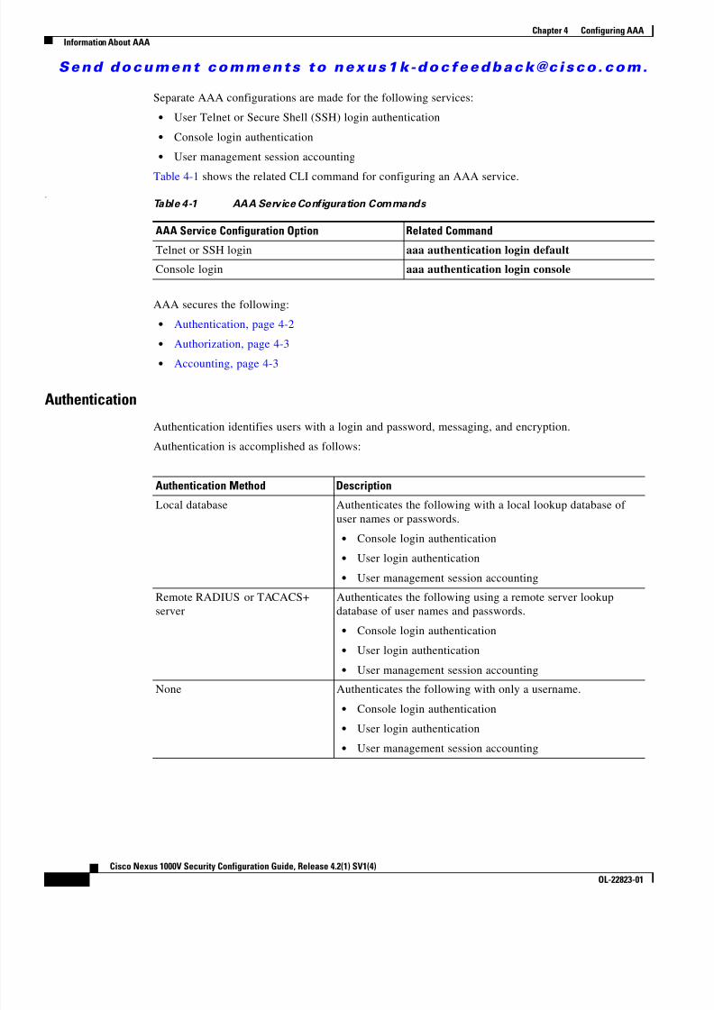
8/13/2019 n1000v Security
http://slidepdf.com/reader/full/n1000v-security 54/234
S e n d d o c u m e n t c o m m e n t s t o n e x u s 1 k - d o c f e e d b a c k @ c i s c o . c o m .
4-2Cisco Nexus 1000V Security Configuration Guide, Release 4.2(1) SV1(4)
OL-22823-01
Chapter 4 Configuring AAAInformation About AAA
Separate AAA configurations are made for the following services:
• User Telnet or Secure Shell (SSH) login authentication
• Console login authentication
• User management session accounting
Table 4-1 shows the related CLI command for configuring an AAA service..
AAA secures the following:
• Authentication, page 4-2
• Authorization, page 4-3
• Accounting, page 4-3
Authentication
Authentication identifies users with a login and password, messaging, and encryption.
Authentication is accomplished as follows:
Table 4-1 AAA Service Configuration Commands
AAA Service Configuration Option Related Command
Telnet or SSH login aaa authentication login default
Console login aaa authentication login console
Authentication Method Description
Local database Authenticates the following with a local lookup database ofuser names or passwords.
• Console login authentication
• User login authentication
• User management session accounting
Remote RADIUS or TACACS+server
Authenticates the following using a remote server lookupdatabase of user names and passwords.
• Console login authentication
• User login authentication
• User management session accounting
None Authenticates the following with only a username.
• Console login authentication • User login authentication
• User management session accounting

8/13/2019 n1000v Security
http://slidepdf.com/reader/full/n1000v-security 55/234
S e n d d o c u m e n t c o m m e n t s t o n e x u s 1 k - d o c f e e d b a c k @ c i s c o . c o m .
4-3Cisco Nexus 1000V Security Configuration Guide, Release 4.2(1) SV1(4)
OL-22823-01
Chapter 4 Configuring AAAInformation About AAA
Figure 4-1 Authenticating User Log In
Authorization
Authorization restricts the actions that a user is allowed to perform.
Accounting
Accounting tracks and maintains a log of every SVS management session. You can use this informationto generate reports for troubleshooting and auditing purposes. You can store accounting logs locally orsend them to remote AAA servers.
2 7 2 7 9 9
End--Access denied
End--Access
permitted
Start
Incoming requestfor access
Is localauthentication
used?
Local usernameand password
database lookup
Wasaccess
permitted?
Remote usernameand password
database lookup
Was aserverfound?
Attempt remoteserver access
No
No
Yes
Yes
No
Yes

8/13/2019 n1000v Security
http://slidepdf.com/reader/full/n1000v-security 56/234
S e n d d o c u m e n t c o m m e n t s t o n e x u s 1 k - d o c f e e d b a c k @ c i s c o . c o m .
4-4Cisco Nexus 1000V Security Configuration Guide, Release 4.2(1) SV1(4)
OL-22823-01
Chapter 4 Configuring AAAPrerequisites for AAA
AAA Server GroupsRemote AAA server groups can provide fail-over in case one remote AAA server fails to respond. If the firstserver in the group fails, the next server in the group is tried until a server responds. Multiple server groupscan provide fail-over for each other in this same way.
If all remote server groups fail, the local database is used for authentication.
Prerequisites for AAAAuthentication using remote AAA servers requires that the following be in place:
• At least one TACACS+ or RADIUS server is IP reachable
• The VSM is configured as an AAA server client.
• A shared secret key is configured on the VSM and the remote AAA server.
See the “Configuring Shared Keys” procedure on page 6-9 .
AAA Guidelines and LimitationsThe Cisco Nexus 1000Vdoes not support user names made up of all numeric characters and does notcreate local user names made up of all numeric characters. If a username made up of all numericcharacters exists on an AAA server and is entered during login, the Cisco Nexus 1000V doesauthenticate the user.
Default SettingsThe following table lists the AAA defaults.
Configuring AAAThis section includes the following topics: • Configuring a Login Authentication Method, page 4-6
• Enabling Login Authentication Failure Messages, page 4-7
Parameters Default
Console authentication method local
Default authentication method local
Login authentication failure messages Disabled

8/13/2019 n1000v Security
http://slidepdf.com/reader/full/n1000v-security 57/234
S e n d d o c u m e n t c o m m e n t s t o n e x u s 1 k - d o c f e e d b a c k @ c i s c o . c o m .
4-5Cisco Nexus 1000V Security Configuration Guide, Release 4.2(1) SV1(4)
OL-22823-01
Chapter 4 Configuring AAAConfiguring AAA
Use the following flow chart to configure AAA.
Flow Chart:Configuring AAA
Configuring AAA
End
Verifying AAA Configuration,page 4-8
Configuring TACACS+,page 6-5
Configuring a LoginAuthentication Method, page 4-6
Are youusing
TACACS+
Yes
No
Are youusing
RADIUS
Yes
No
Configuring RADIUS,page 5-1
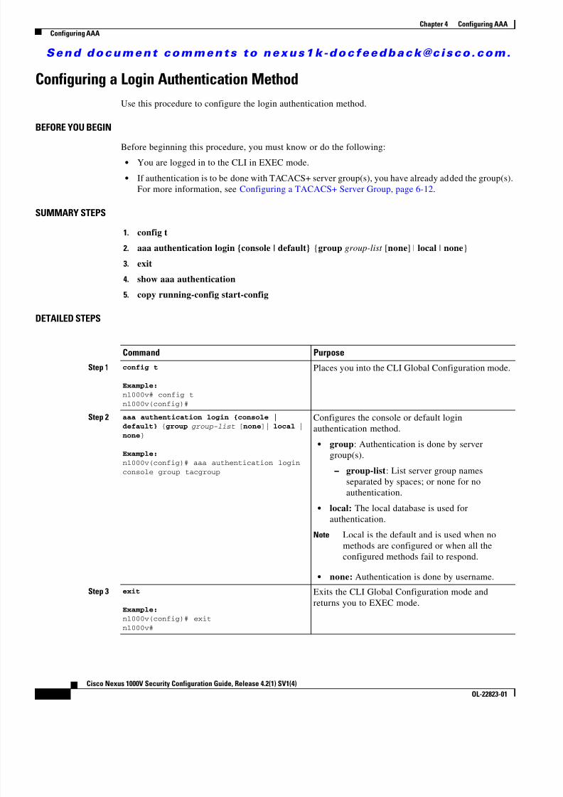
8/13/2019 n1000v Security
http://slidepdf.com/reader/full/n1000v-security 58/234
S e n d d o c u m e n t c o m m e n t s t o n e x u s 1 k - d o c f e e d b a c k @ c i s c o . c o m .
4-6Cisco Nexus 1000V Security Configuration Guide, Release 4.2(1) SV1(4)
OL-22823-01
Chapter 4 Configuring AAAConfiguring AAA
Configuring a Login Authentication MethodUse this procedure to configure the login authentication method.
BEFORE YOU BEGIN
Before beginning this procedure, you must know or do the following:
• You are logged in to the CLI in EXEC mode.
• If authentication is to be done with TACACS+ server group(s), you have already added the group(s).For more information, see Configuring a TACACS+ Server Group, page 6-12 .
SUMMARY STEPS
1. config t
2. aaa authentication login {console | default} {group group-list [none ] | local | none }
3. exit
4. show aaa authentication5. copy running-config start-config
DETAILED STEPS
Command Purpose
Step 1 config t
Example:n1000v# config tn1000v(config)#
Places you into the CLI Global Configuration mode.
Step 2 aaa authentication login {console |default} {group group-list [ none ]| local |none }
Example:n1000v(config)# aaa authentication loginconsole group tacgroup
Configures the console or default loginauthentication method.
• group : Authentication is done by servergroup(s). – group-list : List server group names
separated by spaces; or none for noauthentication.
• local: The local database is used forauthentication.
Note Local is the default and is used when nomethods are configured or when all the
configured methods fail to respond.
• none: Authentication is done by username.
Step 3 exit
Example:n1000v(config)# exitn1000v#
Exits the CLI Global Configuration mode andreturns you to EXEC mode.

8/13/2019 n1000v Security
http://slidepdf.com/reader/full/n1000v-security 59/234
S e n d d o c u m e n t c o m m e n t s t o n e x u s 1 k - d o c f e e d b a c k @ c i s c o . c o m .
4-7Cisco Nexus 1000V Security Configuration Guide, Release 4.2(1) SV1(4)
OL-22823-01
Chapter 4 Configuring AAAConfiguring AAA
Enabling Login Authentication Failure MessagesUse this procedure to enable the login authentication failure message to displays if the remote AAAservers do not respond.
BEFORE YOU BEGIN
Before beginning this procedure, you must know or do the following:
• You are logged in to the CLI in EXEC mode.
• The following is the Login Authentication Failure message:
Remote AAA servers unreachable; local authentication done.Remote AAA servers unreachable; local authentication failed.
SUMMARY STEPS
1. config t
2. aaa authentication login error-enable
3. exit
4. show aaa authentication login error-enable
5. copy running-config start-config
DETAILED STEPS
Step 4 show aaa authentication
Example:n1000v# show aaa authentication
default: group tacgroupconsole: group tacgroup
n1000v#
(Optional) Displays the configured loginauthentication method.
Step 5 copy running-config startup-config
Example:n1000v# copy running-config startup-config
(Optional) Copies the running configuration to thestartup configuration.
Command Purpose
Command PurposeStep 1 config t
Example:n1000v# config tn1000v(config)#
Places you in CLI Global Configuration mode.
Step 2 aaa authentication login error-enable
Example:n1000v(config)# aaa authentication loginerror-enablen1000v(config)#
Enables login authentication failure messages. Thedefault is disabled.

8/13/2019 n1000v Security
http://slidepdf.com/reader/full/n1000v-security 60/234
S e n d d o c u m e n t c o m m e n t s t o n e x u s 1 k - d o c f e e d b a c k @ c i s c o . c o m .
4-8Cisco Nexus 1000V Security Configuration Guide, Release 4.2(1) SV1(4)
OL-22823-01
Chapter 4 Configuring AAAVerifying AAA Configuration
Verifying AAA ConfigurationTo display AAA configuration information, perform one of the following tasks:
Example 4-1 show aaa authentication
n1000v# show aaa authentication login error-enable disabled
Example 4-2 show running config aaa
n1000v# show running-config aaa allversion 4.0(1)aaa authentication login default localaaa accounting default localno aaa authentication login error-enableno aaa authentication login mschap enableno radius-server directed-requestno snmp-server enable traps aaa server-state-change
Step 3 exit
Example:n1000v(config)# exitn1000v#
Exits CLI Global Configuration mode and returnsyou to EXEC mode.
Step 4 show aaa authentication login error-enable
Example:
n1000v# show aaa authentication login error-enableenabledn1000v#
(Optional) Displays the login failure messageconfiguration.
Step 5 copy running-config startup-config
Example:n1000v# copy running-config startup-config
(Optional) Copies the running configuration to thestartup configuration.
Command Purpose
Command Purpose
show aaa authentication [login {error-enable |mschap }]
Displays AAA authentication information.
See Example 4-1 on page 4-8
show aaa groups Displays the AAA server group configuration.
show running-config aaa [all] Displays the AAA configuration in the runningconfiguration.
See Example 4-2 on page 4-8show startup-config aaa Displays the AAA configuration in the startup
configuration.
See Example 4-3 on page 4-9

8/13/2019 n1000v Security
http://slidepdf.com/reader/full/n1000v-security 61/234
S e n d d o c u m e n t c o m m e n t s t o n e x u s 1 k - d o c f e e d b a c k @ c i s c o . c o m .
4-9Cisco Nexus 1000V Security Configuration Guide, Release 4.2(1) SV1(4)
OL-22823-01
Chapter 4 Configuring AAAExample AAA Configuration
no tacacs-server directed-requestn1000v#
Example 4-3 show startup-config aaa
n1000v# show startup-config aaa
version 4.0(1)svs#
Example AAA ConfigurationThe following is an AAA configuration example:
aaa authentication login default group tacacsaaa authentication login console group tacacs
Additional ReferencesFor additional information related to implementing AAA, see the following sections:
• Related Documents, page 4-9
• Standards, page 4-9
Related Documents
Standards
Related Topic Document Title
System Management Cisco Nexus 1000V System Management Configuration Guide, Release4.2(1)SV1(4)
CLI Cisco Nexus 1000V Getting Started Guide, Release 4.2(1)SV1(4)
TACACS+ Security protocol Chapter 6, “Configuring TACACS+”
Standards Title
No new or modified standards are supported by this
feature, and support for existing standards has not beenmodified by this feature.
—

8/13/2019 n1000v Security
http://slidepdf.com/reader/full/n1000v-security 62/234

8/13/2019 n1000v Security
http://slidepdf.com/reader/full/n1000v-security 63/234
C H A P T E R
S e n d d o c u m e n t c o m m e n t s t o n e x u s 1 k - d o c f e e d b a c k @ c i s c o . c o m .
5-1Cisco Nexus 1000V Security Configuration Guide, Release 4.2(1) SV1(4)
OL-22823-01
5Configuring RADIUS
This chapter describes how to configure RADIUS protocol on Cisco NX-OS devices.
This chapter includes the following sections:
• Information About RADIUS, page 5-1
• Prerequisites for RADIUS, page 5-4
• Guidelines and Limitations, page 5-4
• Default Settings, page 5-5
• Configuring RADIUS Servers, page 5-5
• Verifying RADIUS Configuration, page 5-22
• Displaying RADIUS Server Statistics, page 5-22
• Example RADIUS Configuration, page 5-22
• Additional References, page 5-22
• Feature History for RADIUS, page 5-23
Information About RADIUSThe RADIUS distributed client/server system allows you to secure networks against unauthorizedaccess. In the Cisco implementation, RADIUS clients run on Cisco NX-OS devices and sendauthentication and accounting requests to a central RADIUS server that contains all user authenticationand network service access information.
This section includes the following topics:
• RADIUS Network Environments, page 5-1
• RADIUS Operation, page 5-2
• Vendor-Specific Attributes, page 5-3
RADIUS Network EnvironmentsRADIUS can be implemented in a variety of network environments that require high levels of securitywhile maintaining network access for remote users.
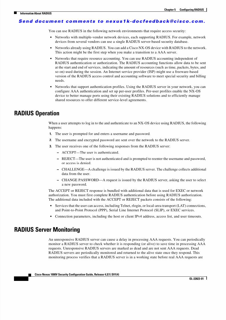
8/13/2019 n1000v Security
http://slidepdf.com/reader/full/n1000v-security 64/234
S e n d d o c u m e n t c o m m e n t s t o n e x u s 1 k - d o c f e e d b a c k @ c i s c o . c o m .
5-2Cisco Nexus 1000V Security Configuration Guide, Release 4.2(1) SV1(4)
OL-22823-01
Chapter 5 Configuring RADIUSInformation About RADIUS
You can use RADIUS in the following network environments that require access security:
• Networks with multiple-vendor network devices, each supporting RADIUS. For example, networkdevices from several vendors can use a single RADIUS server-based security database.
• Networks already using RADIUS. You can add a Cisco NX-OS device with RADIUS to the network.This action might be the first step when you make a transition to a AAA server.
• Networks that require resource accounting. You can use RADIUS accounting independent ofRADIUS authentication or authorization. The RADIUS accounting functions allow data to be sentat the start and end of services, indicating the amount of resources (such as time, packets, bytes, andso on) used during the session. An Internet service provider (ISP) might use a freeware-basedversion of the RADIUS access control and accounting software to meet special security and billingneeds.
• Networks that support authentication profiles. Using the RADIUS server in your network, you canconfigure AAA authentication and set up per-user profiles. Per-user profiles enable the NX-OSdevice to better manage ports using their existing RADIUS solutions and to efficiently manageshared resources to offer different service-level agreements.
RADIUS OperationWhen a user attempts to log in to the and authenticate to an NX-OS device using RADIUS, the followinghappens:
1. The user is prompted for and enters a username and password.
2. The username and encrypted password are sent over the network to the RADIUS server.
3. The user receives one of the following responses from the RADIUS server: – ACCEPT—The user is authenticated. – REJECT—The user is not authenticated and is prompted to reenter the username and password,
or access is denied.
– CHALLENGE—A challenge is issued by the RADIUS server. The challenge collects additionaldata from the user.
– CHANGE PASSWORD—A request is issued by the RADIUS server, asking the user to selecta new password.
The ACCEPT or REJECT response is bundled with additional data that is used for EXEC or networkauthorization. You must first complete RADIUS authentication before using RADIUS authorization.The additional data included with the ACCEPT or REJECT packets consists of the following:
• Services that the user can access, including Telnet, rlogin, or local-area transport (LAT) connections,and Point-to-Point Protocol (PPP), Serial Line Internet Protocol (SLIP), or EXEC services.
• Connection parameters, including the host or client IPv4 address, access list, and user timeouts.
RADIUS Server MonitoringAn unresponsive RADIUS server can cause a delay in processing AAA requests. You can periodicallymonitor a RADIUS server to check whether it is responding (or alive) to save time in processing AAArequests. Unresponsive RADIUS servers are marked as dead and are not sent AAA requests. DeadRADIUS servers are periodically monitored and returned to the alive state once they respond. Thismonitoring process verifies that a RADIUS server is in a working state before real AAA requests are

8/13/2019 n1000v Security
http://slidepdf.com/reader/full/n1000v-security 65/234
S e n d d o c u m e n t c o m m e n t s t o n e x u s 1 k - d o c f e e d b a c k @ c i s c o . c o m .
5-3Cisco Nexus 1000V Security Configuration Guide, Release 4.2(1) SV1(4)
OL-22823-01
Chapter 5 Configuring RADIUSInformation About RADIUS
sent its way. Whenever a RADIUS server changes to the dead or alive state, a Simple NetworkManagement Protocol (SNMP) trap is generated and an error message is displayed indicating that afailure is taking place. See Figure 5-1 .
Figure 5-1 RADIUS Server States
Note The monitoring interval for alive servers and dead servers are different and can be configured by the user.The RADIUS server monitoring is performed by sending a test authentication request to the RADIUSserver.
Vendor-Specific AttributesThe Internet Engineering Task Force (IETF) draft standard specifies a method for communicating VSAsbetween the network access server and the RADIUS server. The IETF uses attribute 26. VSAs allowvendors to support their own extended attributes that are not suitable for general use. The Cisco RADIUSimplementation supports one vendor-specific option using the format recommended in the specification.The Cisco vendor ID is 9, and the supported option is vendor type 1, which is named cisco-av-pair. Thevalue is a string with the following format:
protocol : attribute separator value *
The protocol is a Cisco attribute for a particular type of authorization, separator is = (equal sign) formandatory attributes, and * (asterisk) indicates optional attributes.
When you use RADIUS servers for authentication, the RADIUS protocol directs the RADIUS server toreturn user attributes, such as authorization information, along with authentication results. This
authorization information is specified through VSAs.The following are supported VSA protocol options:
• Shell—Protocol used in access-accept packets to provide user profile information.
• Accounting—Protocol used in accounting-request packets. If a value contains any white spaces, youshould enclose the value within double quotation marks.
Noresponse
Test
Test
Idle timerexpired
DirectedAAA request
Dead timer expired
Response fromremote server
AAA packetssent
Alive
Alive and used
Dead andtesting
Alive andtesting Dead
Applicationrequest
Processapplication
request
1 5 4 5 3 4

8/13/2019 n1000v Security
http://slidepdf.com/reader/full/n1000v-security 66/234
S e n d d o c u m e n t c o m m e n t s t o n e x u s 1 k - d o c f e e d b a c k @ c i s c o . c o m .
5-4Cisco Nexus 1000V Security Configuration Guide, Release 4.2(1) SV1(4)
OL-22823-01
Chapter 5 Configuring RADIUSPrerequisites for RADIUS
The following are supported attributes:
• roles—Lists all the roles to which the user belongs. The value field is a string that lists the rolenames delimited by white space. For example, if the user belongs to roles network-operator andvdc-admin, the value field would be “network-operator vdc-admin.” This attribute, which theRADIUS server sends in the VSA portion of the Access-Accept frames, can only be used with the
shell protocol value. The following examples show the roles attribute as supported by Cisco ACS:shell:roles=“network-operator vdc-admin”
shell:roles*“network-operator vdc-admin”
The following examples show the roles attribute as supported by FreeRADIUS:
Cisco-AVPair = ”shell:roles=\“network-operator vdc-admin\””
Cisco-AVPair = “shell:roles*\“network-operator vdc-admin\””
If you are using Cisco ACS and intend to use the same ACS group for both Cisco Nexus 1000V andCisco UCS authentication, use the following roles attribute:
cisco-av-pair*shell:roles="network-admin admin"
Note When you specify a VSA as shell:roles*"network-operator vdc-admin" or"shell:roles*\"network-operator vdc-admin\"", this VSA is flagged as an optional attribute andother Cisco devices ignore this attribute.
• accountinginfo—Stores accounting information in addition to the attributes covered by a standardRADIUS accounting protocol. This attribute is sent only in the VSA portion of the Account-Requestframes from the RADIUS client on the switch. It can be used only with the accounting protocol dataunits (PDUs).
Prerequisites for RADIUSRADIUS has the following prerequisites:
• You already know the RADIUS server IP addresses or hostnames.
• You already know the key(s) used to secure RADIUS communication in your network.
• The device is already configured as a RADIUS client of the AAA servers.
Guidelines and LimitationsRADIUS has the following guidelines and limitations:
• You can configure a maximum of 64 RADIUS servers.
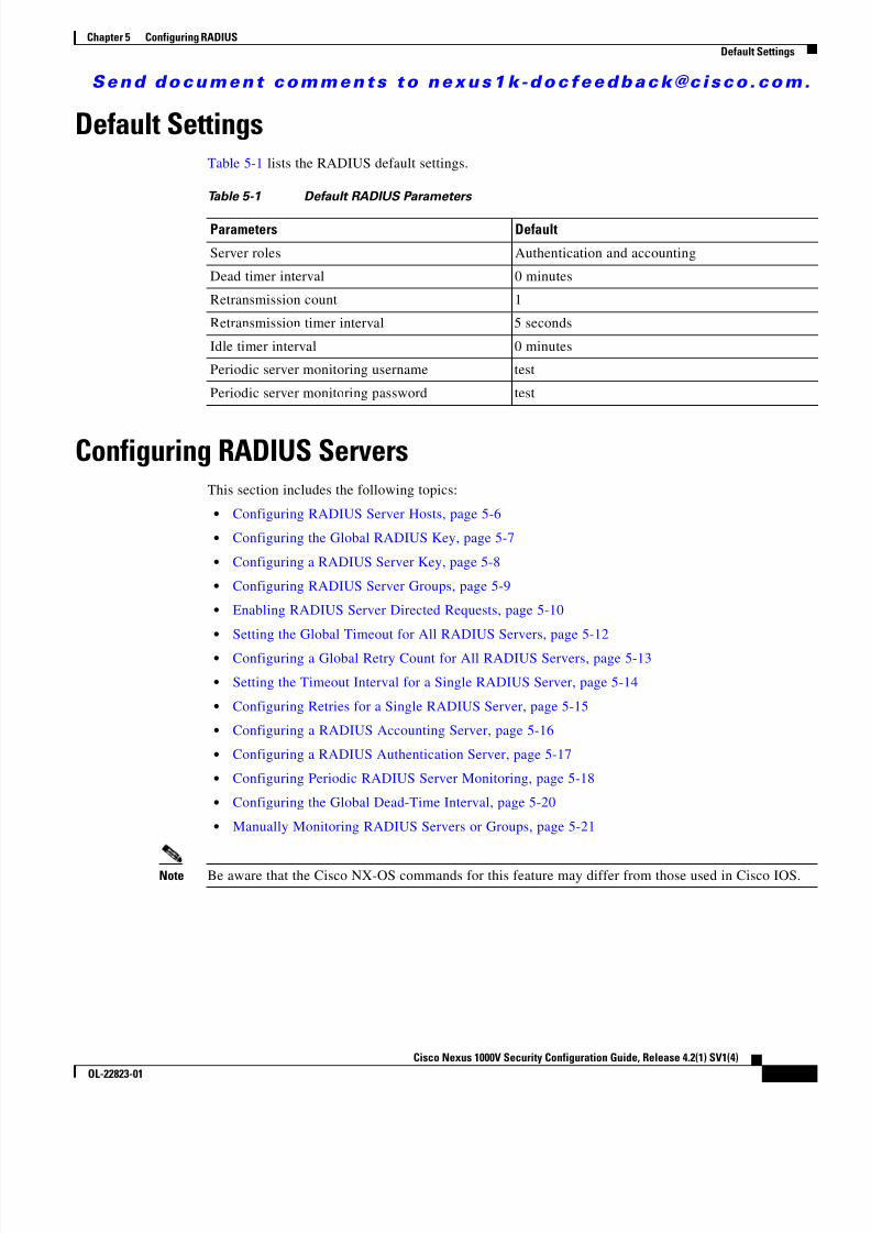
8/13/2019 n1000v Security
http://slidepdf.com/reader/full/n1000v-security 67/234
S e n d d o c u m e n t c o m m e n t s t o n e x u s 1 k - d o c f e e d b a c k @ c i s c o . c o m .
5-5Cisco Nexus 1000V Security Configuration Guide, Release 4.2(1) SV1(4)
OL-22823-01
Chapter 5 Configuring RADIUSDefault Settings
Default SettingsTable 5-1 lists the RADIUS default settings.
Configuring RADIUS ServersThis section includes the following topics:
• Configuring RADIUS Server Hosts, page 5-6
• Configuring the Global RADIUS Key, page 5-7
• Configuring a RADIUS Server Key, page 5-8
• Configuring RADIUS Server Groups, page 5-9
• Enabling RADIUS Server Directed Requests, page 5-10
• Setting the Global Timeout for All RADIUS Servers, page 5-12
• Configuring a Global Retry Count for All RADIUS Servers, page 5-13
• Setting the Timeout Interval for a Single RADIUS Server, page 5-14
• Configuring Retries for a Single RADIUS Server, page 5-15
• Configuring a RADIUS Accounting Server, page 5-16
• Configuring a RADIUS Authentication Server, page 5-17
• Configuring Periodic RADIUS Server Monitoring, page 5-18
• Configuring the Global Dead-Time Interval, page 5-20
• Manually Monitoring RADIUS Servers or Groups, page 5-21
Note Be aware that the Cisco NX-OS commands for this feature may differ from those used in Cisco IOS.
Table 5-1 Default RADIUS Parameters
Parameters Default
Server roles Authentication and accounting
Dead timer interval 0 minutes
Retransmission count 1
Retransmission timer interval 5 seconds
Idle timer interval 0 minutes
Periodic server monitoring username test
Periodic server monitoring password test
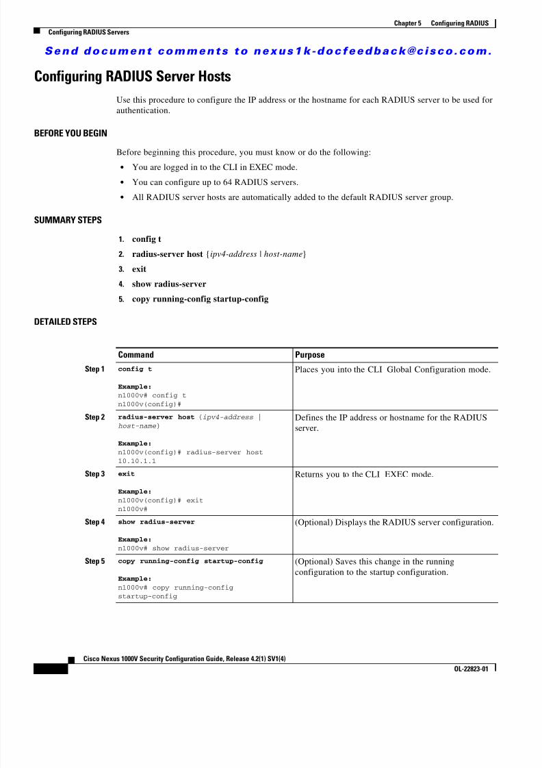
8/13/2019 n1000v Security
http://slidepdf.com/reader/full/n1000v-security 68/234
S e n d d o c u m e n t c o m m e n t s t o n e x u s 1 k - d o c f e e d b a c k @ c i s c o . c o m .
5-6Cisco Nexus 1000V Security Configuration Guide, Release 4.2(1) SV1(4)
OL-22823-01
Chapter 5 Configuring RADIUSConfiguring RADIUS Servers
Configuring RADIUS Server HostsUse this procedure to configure the IP address or the hostname for each RADIUS server to be used forauthentication.
BEFORE YOU BEGINBefore beginning this procedure, you must know or do the following:
• You are logged in to the CLI in EXEC mode.
• You can configure up to 64 RADIUS servers.
• All RADIUS server hosts are automatically added to the default RADIUS server group.
SUMMARY STEPS
1. config t
2. radius-server host {ipv4-address | host-name }
3. exit4. show radius-server
5. copy running-config startup-config
DETAILED STEPS
Command Purpose
Step 1 config t
Example:n1000v# config t
n1000v(config)#
Places you into the CLI Global Configuration mode.
Step 2 radius-server host { ipv4-address |host-name }
Example:n1000v(config)# radius-server host10.10.1.1
Defines the IP address or hostname for the RADIUSserver.
Step 3 exit
Example:n1000v(config)# exitn1000v#
Returns you to the CLI EXEC mode.
Step 4 show radius-server
Example:n1000v# show radius-server
(Optional) Displays the RADIUS server configuration.
Step 5 copy running-config startup-config
Example:n1000v# copy running-configstartup-config
(Optional) Saves this change in the runningconfiguration to the startup configuration.

8/13/2019 n1000v Security
http://slidepdf.com/reader/full/n1000v-security 69/234
S e n d d o c u m e n t c o m m e n t s t o n e x u s 1 k - d o c f e e d b a c k @ c i s c o . c o m .
5-7Cisco Nexus 1000V Security Configuration Guide, Release 4.2(1) SV1(4)
OL-22823-01
Chapter 5 Configuring RADIUSConfiguring RADIUS Servers
Configuring the Global RADIUS KeyUse this procedure to configure the key that is used by all RADIUS servers to authenticate with the CiscoNexus 1000V.
BEFORE YOU BEGINBefore beginning this procedure, you must know or do the following:
• You are logged in to the CLI in EXEC mode.
• You know the global key that is used for RADIUS server authentication.
SUMMARY STEPS
1. config t
2. radius-server key [0 | 7] key-value
3. exit
4. show radius-server5. copy running-config startup-config
DETAILED STEPS
To configure a global preshared key, follow these steps:
Command Purpose
Step 1 config t
Example:n1000v# config t
n1000v(config)#
Places you into the CLI Global Configuration mode.
Step 2 radius-server key [ 0 | 7 ] key-value
Example:n1000v(config)# radius-server key 0QsEfThUkO
Specifies a preshared key for all RADIUS servers. Youcan specify a clear text ( 0) or encrypted ( 7) presharedkey. The default format is clear text. The maximumlength is 63 characters.
By default, no preshared key is configured.
Step 3 exit
Example:n1000v(config)# exitn1000v#
Returns you to the CLI EXEC mode.
Step 4 show radius-server
Example:n1000v# show radius-server
(Optional) Displays the RADIUS server configuration.
Note The preshared keys are saved in encryptedform in the running configuration. Use theshow running-config command to display theencrypted preshared keys.
Step 5 copy running-config startup-config
Example:n1000v# copy running-configstartup-config
(Optional) Saves this change in the runningconfiguration to the startup configuration.

8/13/2019 n1000v Security
http://slidepdf.com/reader/full/n1000v-security 70/234
S e n d d o c u m e n t c o m m e n t s t o n e x u s 1 k - d o c f e e d b a c k @ c i s c o . c o m .
5-8Cisco Nexus 1000V Security Configuration Guide, Release 4.2(1) SV1(4)
OL-22823-01
Chapter 5 Configuring RADIUSConfiguring RADIUS Servers
Configuring a RADIUS Server KeyUse this procedure to configure a key for a single RADIUS server host.
BEFORE YOU BEGIN
Before beginning this procedure, you must know or do the following:
• You are logged in to the CLI in EXEC mode.
• You have the key to be used for the remote RADIUS host.
SUMMARY STEPS
1. config t
2. radius-server host {ipv4-address | host-name } key key-value
3. exit
4. show radius-server
5. copy running-config startup-config
DETAILED STEPS
Command Purpose
Step 1 config t
Example:n1000v# config tn1000v(config)#
Places you into the CLI Global Configuration mode.
Step 2 radius-server host { ipv4-address |host-name
} key [ 0 | 7 ]key-value
Example:n1000v(config)# radius-server host10.10.1.1 key 0 PlIjUhYg
Specifies a preshared key for a specific RADIUS
server. You can specify a clear text ( 0) or encrypted ( 7)preshared key. The default format is clear text. Themaximum length is 63 characters.
This preshared key is used instead of the globalpreshared key.
Step 3 exit
Example:n1000v(config)# exitn1000v#
Returns you to the CLI EXEC mode.
Step 4 show radius-server
Example:
n1000v# show radius-server
(Optional) Displays the RADIUS server configuration.
Note The preshared keys are saved in encrypted
form in the running configuration. Use theshow running-config command to display theencrypted preshared keys.
Step 5 copy running-config startup-config
Example:n1000v# copy running-configstartup-config
(Optional) Saves this change in the runningconfiguration to the startup configuration.

8/13/2019 n1000v Security
http://slidepdf.com/reader/full/n1000v-security 71/234
S e n d d o c u m e n t c o m m e n t s t o n e x u s 1 k - d o c f e e d b a c k @ c i s c o . c o m .
5-9Cisco Nexus 1000V Security Configuration Guide, Release 4.2(1) SV1(4)
OL-22823-01
Chapter 5 Configuring RADIUSConfiguring RADIUS Servers
Configuring RADIUS Server GroupsUse this procedure to configure a RADIUS server group whose member servers share authenticationfunctions.
BEFORE YOU BEGINBefore beginning this procedure, you must know or do the following:
• You are logged in to the CLI in EXEC mode.
• All servers in a RADIUS server group must belong to the RADIUS protocol.
• The servers in the group are tried in the same order in which you configure them.
SUMMARY STEPS
1. config t
2. aaa group server radius group-name
3. server {ipv4-address | server-name }4. deadtime minutes
5. use-vrf vrf-name
6. (Optional) source-interface {interface-type } {interface-number }
7. (Optional) show radius-server groups [group-name ]
8. (Optional) copy running-config startup-config
DETAILED STEPS
Command PurposeStep 1 config t
Example:n1000v# config tn1000v(config)#
Places you into the CLI Global Configuration mode.
Step 2 aaa group server radius group-name
Example:n1000v(config)# aaa group server radiusRadServern1000v(config-radius)#
Creates a RADIUS server group and enters theRADIUS server group configuration mode for thatgroup. The group-name argument is a case-sensitivealphanumeric string with a maximum length of 127characters.
Step 3 server { ipv4-address | server-name }
Example:n1000v(config-radius)# server 10.10.1.1
Configures the RADIUS server as a member of theRADIUS server group.
Tip If the specified RADIUS server is not found,configure it using the radius-server host command and retry this command.

8/13/2019 n1000v Security
http://slidepdf.com/reader/full/n1000v-security 72/234
S e n d d o c u m e n t c o m m e n t s t o n e x u s 1 k - d o c f e e d b a c k @ c i s c o . c o m .
5-10Cisco Nexus 1000V Security Configuration Guide, Release 4.2(1) SV1(4)
OL-22823-01
Chapter 5 Configuring RADIUSConfiguring RADIUS Servers
Enabling RADIUS Server Directed RequestsUse this procedure to let users designate the RADIUS server to send their authentication request to. This
is called a directed-request.If you enable this option, a user can log in as username @vrfname :hostname, where vrfname is the VRFto use and hostname is the name of a configured RADIUS server.
Note User-specified logins are supported only for Telnet sessions.
Step 4 deadtime minutes
Example:n1000v(config-radius)# deadtime 30
(Optional) Configures the monitoring dead time. Thedefault is 0 minutes. The range is from 1 through 1440.
Note If the dead-time interval for a RADIUS servergroup is greater than zero (0), that value takesprecedence over the global dead-time value(see the “Configuring the Global Dead-TimeInterval” section on page 5-20 ).
Step 5 use-vrf vrf-name
Example:n1000v(config-radius)# use-vrf vrf1
(Optional) Specifies the VRF to use to contact theservers in the server group.
Step 6 source-interface { interface-type } { interface-number }
Example:n1000v(config-radius)# source-interface
mgmt0
n1000v(config-radius)#
(Optional) Specifies a source interface to be used toreach the RADIUS server.
• loopback = Virtual interface number from 0 to1023
• mgmt = Management interface 0 • null = Null interface 0
• port-channel = Port channel number from 1 to4096
Step 7 show radius-server groups [ group-name ] (Optional) Displays the RADIUS server groupconfiguration.
Example:n1000v(config-radius)# show radius-server grouptotal number of groups:2
following RADIUS server groups are configured: group Radserver: server: 10.10.1.1 deadtime is 30 group test: deadtime is 30
Step 8 copy running-config startup-config
Example:n1000v(config-radius)# copyrunning-config startup-config
(Optional) Saves this change in the runningconfiguration to the startup configuration.
Command Purpose

8/13/2019 n1000v Security
http://slidepdf.com/reader/full/n1000v-security 73/234
S e n d d o c u m e n t c o m m e n t s t o n e x u s 1 k - d o c f e e d b a c k @ c i s c o . c o m .
5-11Cisco Nexus 1000V Security Configuration Guide, Release 4.2(1) SV1(4)
OL-22823-01
Chapter 5 Configuring RADIUSConfiguring RADIUS Servers
BEFORE YOU BEGIN
Before beginning this procedure, you must know or do the following:
• You are logged in to the CLI in EXEC mode.
• Directed requests are disabled by default.
SUMMARY STEPS
1. config t
2. radius-server directed-request
3. exit
4. show radius-server directed-request
5. copy running-config startup-config
DETAILED STEPS
Command Purpose
Step 1 config t
Example:n1000v# config tn1000v(config)#
Places you into the CLI Global Configuration mode.
Step 2 n1000v(config)# radius-serverdirected-request
Example:n1000v(config)# radius-serverdirected-request
Enables directed requests. The default is disabled.
Step 3exit
Example:n1000v(config)# exitn1000v#
Returns you to the CLI EXEC mode.
Step 4 show radius-server directed-request
Example:n1000v# show radius-serverdirected-request
(Optional) Displays the directed request configuration.
Step 5 copy running-config startup-config
Example:n1000v# copy running-configstartup-config
(Optional) Copies the running configuration to thestartup configuration.

8/13/2019 n1000v Security
http://slidepdf.com/reader/full/n1000v-security 74/234
S e n d d o c u m e n t c o m m e n t s t o n e x u s 1 k - d o c f e e d b a c k @ c i s c o . c o m .
5-12Cisco Nexus 1000V Security Configuration Guide, Release 4.2(1) SV1(4)
OL-22823-01
Chapter 5 Configuring RADIUSConfiguring RADIUS Servers
Setting the Global Timeout for All RADIUS ServersUse this procedure to configure the global timeout interval specifying how long to wait for a responsefrom a RADIUS server before declaring a timeout failure.
BEFORE YOU BEGINBefore beginning this procedure, you must know or do the following:
• You are logged in to the CLI in EXEC mode.
• The timeout specified in the “Setting the Timeout Interval for a Single RADIUS Server” procedureon page 5-14 overrides the global RADIUS timeout.
SUMMARY STEPS
1. config t
2. radius-server timeout seconds
3.exit
4. show radius-server
5. copy running-config startup-config
DETAILED STEPS
Command Purpose
Step 1 config t
Example:n1000v# config tn1000v(config)#
Places you into the CLI Global Configuration mode.
Step 2 radius-server timeout seconds
Example:n1000v(config)# radius-server timeout 10
Specifies the transmission timeout interval forRADIUS servers. The default timeout interval is 5seconds and the allowable range is from 1 to 60seconds.
Step 3 exit
Example:n1000v(config)# exitn1000v#
Returns you to the CLI EXEC mode.
Step 4 show radius-server
Example:n1000v# show radius-server
(Optional) Displays the RADIUS serverconfiguration.
Step 5 copy running-config startup-config
Example:n1000v# copy running-config startup-config
(Optional) Saves this change in the runningconfiguration to the startup configuration.

8/13/2019 n1000v Security
http://slidepdf.com/reader/full/n1000v-security 75/234
S e n d d o c u m e n t c o m m e n t s t o n e x u s 1 k - d o c f e e d b a c k @ c i s c o . c o m .
5-13Cisco Nexus 1000V Security Configuration Guide, Release 4.2(1) SV1(4)
OL-22823-01
Chapter 5 Configuring RADIUSConfiguring RADIUS Servers
Configuring a Global Retry Count for All RADIUS ServersUse this procedure to configure the maximum number of times to retry transmitting to a RADIUS serverbefore reverting to local authentication.This setting is applied to all RADIUS servers.
BEFORE YOU BEGINBefore beginning this procedure, you must know or do the following:
• You are logged in to the CLI in EXEC mode.
• By default, retransmission to a RADIUS server is only tried once before reverting to localauthentication.
• You can increase the number of retries up to a maximum of five.
• The retry count specified for a single RADIUS server in the “Configuring Retries for a SingleRADIUS Server” procedure on page 5-15 , overrides this global setting.
SUMMARY STEPS
1. config t
2. radius-server retransmission count
3. radius-server timeout seconds
4. exit
5. show radius-server
6. copy running-config startup-config
DETAILED STEPS
Command PurposeStep 1 config t
Example:n1000v# config tn1000v(config)#
Places you into the CLI Global Configuration mode.
Step 2 radius-server retransmit count
Example:n1000v(config)# radius-server retransmit 3
Defines the number of retransmits allowed beforereverting to local authentication. This is a globalsetting that applies to all RADIUS servers. Thedefault number of retransmits is 1 and the range isfrom 0 to 5.
Step 3 exit
Example:n1000v(config)# exitn1000v#
Returns you to the CLI EXEC mode.

8/13/2019 n1000v Security
http://slidepdf.com/reader/full/n1000v-security 76/234
S e n d d o c u m e n t c o m m e n t s t o n e x u s 1 k - d o c f e e d b a c k @ c i s c o . c o m .
5-14Cisco Nexus 1000V Security Configuration Guide, Release 4.2(1) SV1(4)
OL-22823-01
Chapter 5 Configuring RADIUSConfiguring RADIUS Servers
Setting the Timeout Interval for a Single RADIUS ServerUse this procedure to configure how long to wait for a response from a RADIUS server before declaringa timeout failure.
BEFORE YOU BEGIN
Before beginning this procedure, you must know or do the following: • You are logged in to the CLI in EXEC mode.
• The timeout specified for a single RADIUS server overrides the timeout defined in the “Setting theGlobal Timeout for All RADIUS Servers” procedure on page 5-12 .
SUMMARY STEPS
1. config t
2. radius-server host {ipv4-address | host-name } timeout seconds
3. exit
4. show radius-server
5. copy running-config startup-config
DETAILED STEPS
Step 4 show radius-server
Example:n1000v# show radius-server
(Optional) Displays the RADIUS serverconfiguration.
Step 5 copy running-config startup-configExample:n1000v# copy running-config startup-config
(Optional) Saves this change in the runningconfiguration to the startup configuration.
Command Purpose
Command Purpose
Step 1 config t
Example:n1000v# config tn1000v(config)#
Places you into the CLI Global Configuration mode.
Step 2 radius-server host { ipv4-address |host-name } timeout seconds
Example:n1000v(config)# radius-server host server1timeout 10
Specifies the timeout interval for the specified
server. The default timeout interval is 5 seconds andthe allowable range is from 1 to 60 seconds.
Note The timeout specified for a single RADIUSserver overrides the global RADIUStimeout.
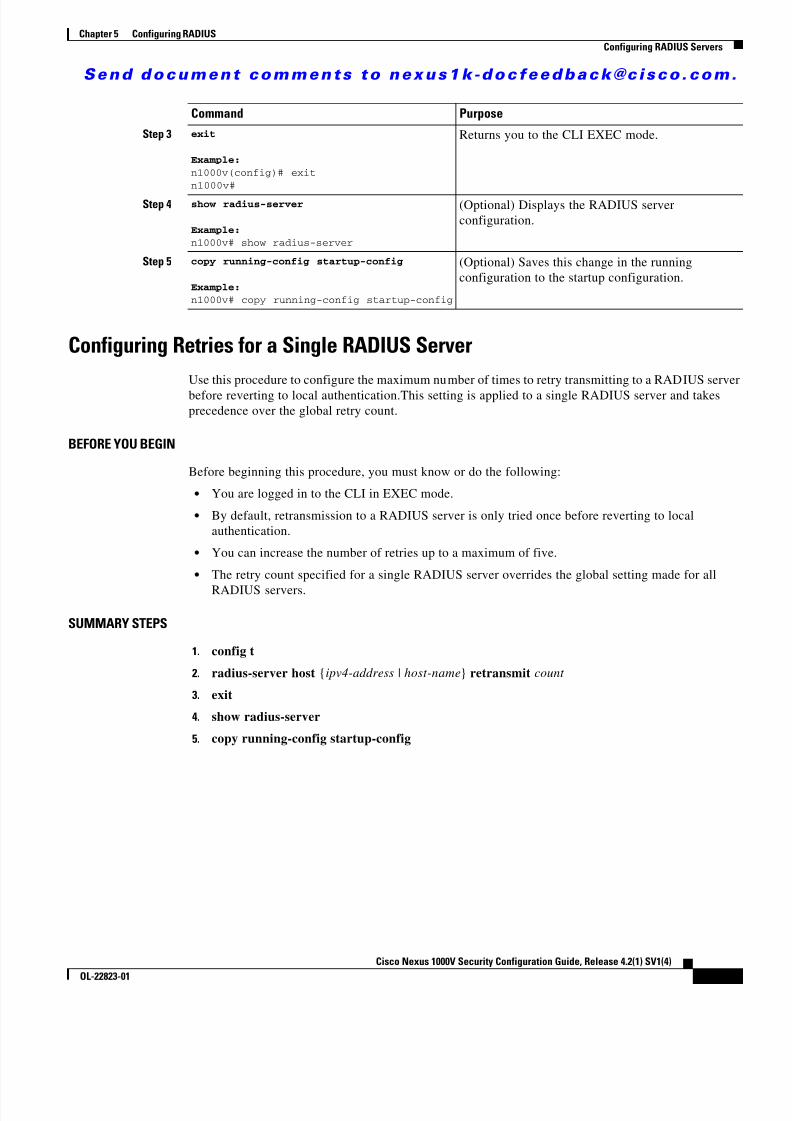
8/13/2019 n1000v Security
http://slidepdf.com/reader/full/n1000v-security 77/234
S e n d d o c u m e n t c o m m e n t s t o n e x u s 1 k - d o c f e e d b a c k @ c i s c o . c o m .
5-15Cisco Nexus 1000V Security Configuration Guide, Release 4.2(1) SV1(4)
OL-22823-01
Chapter 5 Configuring RADIUSConfiguring RADIUS Servers
Configuring Retries for a Single RADIUS ServerUse this procedure to configure the maximum number of times to retry transmitting to a RADIUS serverbefore reverting to local authentication.This setting is applied to a single RADIUS server and takesprecedence over the global retry count.
BEFORE YOU BEGIN
Before beginning this procedure, you must know or do the following:
• You are logged in to the CLI in EXEC mode.
• By default, retransmission to a RADIUS server is only tried once before reverting to localauthentication.
• You can increase the number of retries up to a maximum of five.
• The retry count specified for a single RADIUS server overrides the global setting made for all
RADIUS servers.
SUMMARY STEPS
1. config t
2. radius-server host {ipv4-address | host-name } retransmit count
3. exit
4. show radius-server
5. copy running-config startup-config
Step 3 exit
Example:n1000v(config)# exitn1000v#
Returns you to the CLI EXEC mode.
Step 4 show radius-server
Example:n1000v# show radius-server
(Optional) Displays the RADIUS serverconfiguration.
Step 5 copy running-config startup-config
Example:n1000v# copy running-config startup-config
(Optional) Saves this change in the runningconfiguration to the startup configuration.
Command Purpose

8/13/2019 n1000v Security
http://slidepdf.com/reader/full/n1000v-security 78/234
S e n d d o c u m e n t c o m m e n t s t o n e x u s 1 k - d o c f e e d b a c k @ c i s c o . c o m .
5-16Cisco Nexus 1000V Security Configuration Guide, Release 4.2(1) SV1(4)
OL-22823-01
Chapter 5 Configuring RADIUSConfiguring RADIUS Servers
DETAILED STEPS
Configuring a RADIUS Accounting ServerUse this procedure to configure a server to perform accounting functions.
BEFORE YOU BEGIN
Before beginning this procedure, you must know or do the following:
• You are logged in to the CLI in EXEC mode.
• By default, RADIUS servers are used for both accounting and authentication.
• You know the destination UDP port number for RADIUS accounting messages.
SUMMARY STEPS
1. config t
2. radius-server host {ipv4-address | host-name } acct-port udp-port
3. radius-server host {ipv4-address | host-name } accounting
4. exit
5. show radius-server
6. copy running-config startup-config
Command Purpose
Step 1 config t
Example:n1000v# config tn1000v(config)#
Places you into the CLI Global Configuration mode.
Step 2 radius-server host { ipv4-address |host-name } retransmit count
Example:n1000v(config)# radius-server host server1retransmit 3
Specifies the retransmission count for a specificserver. The default is the global value.
Note This retransmit count for a single RADIUSserver overrides the global setting for allRADIUS servers.
Step 3 exit
Example:n1000v(config)# exit
n1000v#
Returns you to the CLI EXEC mode.
Step 4 show radius-server
Example:n1000v# show radius-server
(Optional) Displays the RADIUS serverconfiguration.
Step 5 copy running-config startup-config
Example:n1000v# copy running-config startup-config
(Optional) Saves this change in the runningconfiguration to the startup configuration.

8/13/2019 n1000v Security
http://slidepdf.com/reader/full/n1000v-security 79/234
S e n d d o c u m e n t c o m m e n t s t o n e x u s 1 k - d o c f e e d b a c k @ c i s c o . c o m .
5-17Cisco Nexus 1000V Security Configuration Guide, Release 4.2(1) SV1(4)
OL-22823-01
Chapter 5 Configuring RADIUSConfiguring RADIUS Servers
DETAILED STEPS
To configure the authentication and accounting attributes for RADIUS servers, follow these steps:
Configuring a RADIUS Authentication ServerUse this procedure to configure a server to perform authentication functions.
BEFORE YOU BEGIN
Before beginning this procedure, you must know or do the following:
• You are logged in to the CLI in EXEC mode.
• By default, RADIUS servers are used for both accounting and authentication. • You know the destination UDP port number for RADIUS authentication messages.
SUMMARY STEPS
1. config t
2. radius-server host {ipv4-address | host-name } auth-port udp-port
3. radius-server host {ipv4-address | host-name } authentication
Command Purpose
Step 1 config t
Example:n1000v# config tn1000v(config)#
Places you into the CLI Global Configuration mode.
Step 2 radius-server host { ipv4-address |host-name } acct-port udp-port
Example:n1000v(config)# radius-server host10.10.1.1 acct-port 2004
(Optional) Associates a specific host with the UDPport that receives RADIUS accounting messages.The default UDP port is 1812. The range is from 0to 65535.
Step 3 radius-server host { ipv4-address |host-name } accounting
Example:n1000v(config)# radius-server host10.10.1.1 accounting
(Optional) Designates the specific RADIUS host asan accounting server. The default is both accountingand authentication.
Step 4 exit
Example:n1000v(config)# exitn1000v#
Returns you to the CLI EXEC mode.
Step 5 show radius-server
Example:n1000v(config)# show radius-server
(Optional) Displays the RADIUS serverconfiguration.
Step 6 copy running-config startup-config
Example:n1000v# copy running-config startup-config
(Optional) Saves this change in the runningconfiguration to the startup configuration.

8/13/2019 n1000v Security
http://slidepdf.com/reader/full/n1000v-security 80/234

8/13/2019 n1000v Security
http://slidepdf.com/reader/full/n1000v-security 81/234
S e n d d o c u m e n t c o m m e n t s t o n e x u s 1 k - d o c f e e d b a c k @ c i s c o . c o m .
5-19Cisco Nexus 1000V Security Configuration Guide, Release 4.2(1) SV1(4)
OL-22823-01
Chapter 5 Configuring RADIUSConfiguring RADIUS Servers
Note For security reasons, do not configure a username that is in the RADIUS database as a test username.
Note The default idle timer value is 0 minutes. When the idle time interval is 0 minutes, the NX-OS devicedoes not perform periodic RADIUS server monitoring.
SUMMARY STEPS
1. config t
2. radius-server host {ipv4-address | host-name } test {idle-time minutes | password password[idle-time minutes ] | username name [password password [idle-time minutes ]]}
3. radius-server dead-time minutes
4. exit
5. show radius-server
6. copy running-config startup-config
DETAILED STEPS
Command Purpose
Step 1 config t
Example:n1000v# config tn1000v(config)#
Places you into the CLI Global Configuration mode.
Step 2 radius-server host { ipv4-address |host-name } test { idle-time minutes |
password password [ idle-time minutes ] | username name [ password password
[ idle-time minutes ]]}
Example:n1000v(config)# radius-server host10.10.1.1 test username user1 passwordUr2Gd2BH idle-time 3
Specifies parameters for server monitoring. Thedefault username is test and the default password istest. The default value for the idle timer is 0 minutes.The valid range is 0 to 1440 minutes.
Note For periodic RADIUS server monitoring,you must set the idle timer to a value greaterthan 0.
Step 3 radius-server dead-time minutes
Example:n1000v(config)# radius-server dead-time 5
Specifies the number of minutes to wait beforesending a test packet to a RADIUS server that wasdeclared dead. The default value is 0 minutes. Thevalid range is 1 to 1440 minutes.
Step 4 exit
Example:n1000v(config)# exitn1000v#
Returns you to the CLI EXEC mode.

8/13/2019 n1000v Security
http://slidepdf.com/reader/full/n1000v-security 82/234
S e n d d o c u m e n t c o m m e n t s t o n e x u s 1 k - d o c f e e d b a c k @ c i s c o . c o m .
5-20Cisco Nexus 1000V Security Configuration Guide, Release 4.2(1) SV1(4)
OL-22823-01
Chapter 5 Configuring RADIUSConfiguring RADIUS Servers
Configuring the Global Dead-Time IntervalUse this procedure to configure the dead-time interval for all RADIUS servers. The dead-time intervalspecifies the time to wait after declaring a RADIUS server dead, before sending out a test packet todetermine if the server is now alive. The default value is 0 minutes.
Note When the dead-time interval is 0 minutes, RADIUS servers are not marked as dead even if they are notresponding. You can configure the dead-time interval for a RADIUS server group (see the “ConfiguringRADIUS Server Groups” section on page 5-9 ).
BEFORE YOU BEGIN
Before beginning this procedure, you must know or do the following:
• You are logged in to the CLI in EXEC mode.
SUMMARY STEPS
1. config t
2. radius-server deadtime minutes3. exit
4. show radius-server
5. copy running-config startup-config
DETAILED STEPS
To configure the RADIUS dead-time interval, follow these steps:
Step 5 show radius-server
Example:n1000v# show radius-server
(Optional) Displays the RADIUS serverconfiguration.
Step 6 copy running-config startup-configExample:n1000v# copy running-config startup-config
(Optional) Saves this change in the runningconfiguration to the startup configuration.
Command Purpose
Command Purpose
Step 1 config t
Example:n1000v# config tn1000v(config)#
Places you into the CLI Global Configuration mode.
Step 2 n1000v(config)# radius-server deadtime minutes
Example:n1000v(config)# radius-server deadtime 5
Configures the dead-time interval. The default value is0 minutes. The range is from 1 to 1440 minutes.

8/13/2019 n1000v Security
http://slidepdf.com/reader/full/n1000v-security 83/234
S e n d d o c u m e n t c o m m e n t s t o n e x u s 1 k - d o c f e e d b a c k @ c i s c o . c o m .
5-21Cisco Nexus 1000V Security Configuration Guide, Release 4.2(1) SV1(4)
OL-22823-01
Chapter 5 Configuring RADIUSConfiguring RADIUS Servers
Manually Monitoring RADIUS Servers or Groups
Use this procedure to manually send a test message to a RADIUS server or to a server group.
BEFORE YOU BEGIN
Before beginning this procedure, you must know or do the following:
• You are logged in to the CLI in EXEC mode.
SUMMARY STEPS
1. test aaa server radius {ipv4-address | host-name } [vrf vrf-name ] username password
2. test aaa group group-name username password
DETAILED STEPS
Step 3 exit
Example:n1000v(config)# exitn1000v#
Returns you to the CLI EXEC mode.
Step 4 show radius-server
Example:n1000v# show radius-server
(Optional) Displays the RADIUS server configuration.
Step 5 copy running-config startup-config
Example:n1000v# copy running-configstartup-config
(Optional) Saves this change in the runningconfiguration to the startup configuration.
Command Purpose
Command Purpose
Step 1 test aaa server radius { ipv4-address |server-name } [ vrf vrf-name ] username
password
Example:n1000v# test aaa server radius 10.10.1.1user1 Ur2Gd2BH
Sends a test message to a RADIUS server to confirmavailability.
Step 1 test aaa group group-name username password
Example:n1000v# test aaa group RadGroup user2As3He3CI
Sends a test message to a RADIUS server group toconfirm availability.

8/13/2019 n1000v Security
http://slidepdf.com/reader/full/n1000v-security 84/234
S e n d d o c u m e n t c o m m e n t s t o n e x u s 1 k - d o c f e e d b a c k @ c i s c o . c o m .
5-22Cisco Nexus 1000V Security Configuration Guide, Release 4.2(1) SV1(4)
OL-22823-01
Chapter 5 Configuring RADIUSVerifying RADIUS Configuration
Verifying RADIUS ConfigurationUse the commands in this section to verify the RADIUS configuration. For detailed information aboutshow command output, see the Cisco Nexus 1000V Command Reference, Release 4.2(1)SV1(4) .
Displaying RADIUS Server StatisticsUse the following command to display statistics for RADIUS server activity.
show radius-server statistics {hostname | ipv4-address }
Example RADIUS ConfigurationThe following example shows how to configure RADIUS:
radius-server key 7 "ToIkLhPpG"radius-server host 10.10.1.1 key 7 "ShMoMhTl" authentication accountingaaa group server radius RadServer server 10.10.1.1
Additional ReferencesFor additional information related to implementing RADIUS, see the following sections:
• Related Documents, page 5-22
• Standards, page 5-23
Related Documents
Command Purpose
show running-config radius [all ] Displays the RADIUS configuration in therunning configuration.
show startup-config radius Displays the RADIUS configuration in the startupconfiguration.
show radius-server [server-name | ipv4-address ][directed-request | groups | sorted | statistics ]
Displays all configured RADIUS serverparameters.
Related Topic Document TitleCommand reference Cisco Nexus 1000V Command Reference, Release 4.2(1)SV1(4)

8/13/2019 n1000v Security
http://slidepdf.com/reader/full/n1000v-security 85/234
S e n d d o c u m e n t c o m m e n t s t o n e x u s 1 k - d o c f e e d b a c k @ c i s c o . c o m .
5-23Cisco Nexus 1000V Security Configuration Guide, Release 4.2(1) SV1(4)
OL-22823-01
Chapter 5 Configuring RADIUSFeature History for RADIUS
Standards
Feature History for RADIUSThis section provides the RADIUS release history.
Standards Title
No new or modified standards are supported by thisfeature, and support for existing standards has not beenmodified by this feature.
—
Feature Name Releases Feature Information
RADIUS 4.0(4)SV1(1) This feature was introduced.

8/13/2019 n1000v Security
http://slidepdf.com/reader/full/n1000v-security 86/234
S e n d d o c u m e n t c o m m e n t s t o n e x u s 1 k - d o c f e e d b a c k @ c i s c o . c o m .
5-24Cisco Nexus 1000V Security Configuration Guide, Release 4.2(1) SV1(4)
OL-22823-01
Chapter 5 Configuring RADIUSFeature History for RADIUS

8/13/2019 n1000v Security
http://slidepdf.com/reader/full/n1000v-security 87/234
C H A P T E R
S e n d d o c u m e n t c o m m e n t s t o n e x u s 1 k - d o c f e e d b a c k @ c i s c o . c o m .
6-1Cisco Nexus 1000V Security Configuration Guide, Release 4.2(1) SV1(4)
OL-22823-01
6Configuring TACACS+
This chapter describes how to configure the Terminal Access Controller Access Control System Plus(TACACS+) protocol.
This chapter includes the following sections:
• Information About TACACS+, page 6-1
• Prerequisites for TACACS+, page 6-4
• Guidelines and Limitations, page 6-4
• Default Settings, page 6-4
• Configuring TACACS+, page 6-5
• Displaying Statistics for a TACACS+ Host, page 6-22
• Example TACACS+ Configuration, page 6-23
• Additional References, page 6-24
• Feature History for TACACS+, page 6-23
Information About TACACS+You can use TACACS+ to provide centralized validation of users attempting to gain access to a device.TACACS+ services are maintained in a database on a TACACS+ daemon running, typically, on a UNIXor Windows NT workstation. You must have access to and must configure a TACACS+ server before theconfigured TACACS+ features on your device are available.
The TACACS+ security protocol provides centralized validation of users attempting to gain access to adevice. TACACS+ services are maintained in a database on a TACACS+ daemon running, typically, ona UNIX or Windows NT workstation. You must have access to and must configure a TACACS+ serverbefore the configured TACACS+ features on your device are available.
TACACS+ provides for separate authentication, authorization, and accounting services. The TACACS+daemon provides each service independently. Each service can be tied into its own database to takeadvantage of other services available on that server or on the network, depending on the capabilities ofthe daemon.
The TACACS+ client/server protocol uses TCP (TCP port 49) for transport requirements. Centralizedauthentication is provided using the TACACS+ protocol.
This section includes the following topics:
• TACACS+ Operation for User Login, page 6-2

8/13/2019 n1000v Security
http://slidepdf.com/reader/full/n1000v-security 88/234
S e n d d o c u m e n t c o m m e n t s t o n e x u s 1 k - d o c f e e d b a c k @ c i s c o . c o m .
6-2Cisco Nexus 1000V Security Configuration Guide, Release 4.2(1) SV1(4)
OL-22823-01
Chapter 6 Configuring TACACS+Information About TACACS+
• Default TACACS+ Server Encryption Type and Preshared Key, page 6-2
• TACACS+ Server Monitoring, page 6-3
• Vendor-Specific Attributes, page 6-3
TACACS+ Operation for User LoginTHe following sequence of events take place when you attempt to login to a TACACS+ server usingPassword Authentication Protocol (PAP):
1. When a connection is established, the TACACS+ daemon is contacted to obtain the username andpassword.
Note TACACS+ allows an arbitrary conversation between the daemon and the user until the daemonreceives enough information to authenticate the user. This action is usually done by promptingfor a username and password combination, but may include prompts for additional information,such as mother’s maiden name.
2. The TACACS+ daemon provides one of the following responses:
a. ACCEPT—User authentication succeeds and service begins. If user authorization is needed,authorization begins.
b. REJECT—User authentication failed. The TACACS+ daemon either denies further access to theuser or prompts the user to retry the login sequence.
c. ERROR—An error occurred at some time during authentication either at the daemon or in thenetwork connection. If an ERROR response is received, the device tries to use an alternativemethod for authenticating the user.
If further authorization is required after authentication, the user also undergoes an additionalauthorization phase. Users must first successfully complete TACACS+ authentication before
proceeding to TACACS+ authorization.3. If TACACS+ authorization is required, the TACACS+ daemon is contacted and it returns an
ACCEPT or REJECT authorization response. An ACCEPT response contains attributes that are usedto direct the EXEC or NETWORK session for that user and determines the services that the user canaccess.
Services include the following:
• Telnet, rlogin, Point-to-Point Protocol (PPP), Serial Line Internet Protocol (SLIP), or EXECservices
• Connection parameters, including the host or client IP address, access list, and user timeouts
Default TACACS+ Server Encryption Type and Preshared KeyYou must configure the TACACS+ preshared key to authenticate to the TACACS+ server. A presharedkey is a secret text string shared between the device and the TACACS+ server host. The length of the keyis restricted to 63 characters and can include any printable ASCII characters (white spaces are notallowed). You can configure a global preshared secret key for all TACACS+ server configurations.
You can override the global preshared key assignment by explicitly using the key option whenconfiguring and individual TACACS+ server.

8/13/2019 n1000v Security
http://slidepdf.com/reader/full/n1000v-security 89/234
S e n d d o c u m e n t c o m m e n t s t o n e x u s 1 k - d o c f e e d b a c k @ c i s c o . c o m .
6-3Cisco Nexus 1000V Security Configuration Guide, Release 4.2(1) SV1(4)
OL-22823-01
Chapter 6 Configuring TACACS+Information About TACACS+
TACACS+ Server MonitoringUnresponsive TACACS+ servers are marked as dead and are not sent AAA requests. Dead TACACS+servers are periodically monitored and brought back alive once they respond. This process confirms thata TACACS+ server is in a working state before real AAA requests are sent its way. The following figure
shows how a TACACS+ server state change generates a Simple Network Management Protocol (SNMP)trap and an error message showing the failure before it impacts performance.
Figure 6-1 TACACS+ Server States
Note The monitoring interval for alive servers and dead servers are different and can be configured by the user.The TACACS+ server monitoring is performed by sending a test authentication request to the TACACS+server.
Vendor-Specific AttributesThe Internet Engineering Task Force (IETF) draft standard specifies a method for communicatingvendor-specific attributes (VSAs) between the network access server and the TACACS+ server. TheIETF uses attribute 26. VSAs allow vendors to support their own extended attributes that are not suitablefor general use.
Cisco VSA Format
The Cisco TACACS+ implementation supports one vendor-specific option using the formatrecommended in the IETF specification. The Cisco vendor ID is 9, and the supported option is vendortype 1, which is named cisco-av-pair. The value is a string with the following format:
protocol : attribute separator value *
The protocol is a Cisco attribute for a particular type of authorization, separator is = (equal sign) formandatory attributes, and * (asterisk) indicates optional attributes.
Noresponse
Test
Test
Idle timerexpired Directed
AAA request
Dead timer expired
Response fromremote server
AAA packets
sentAlive
Alive and used
Dead andtesting
Alive and
testingDead
Applicationrequest
Processapplication
request
1 5 4 5 3 4

8/13/2019 n1000v Security
http://slidepdf.com/reader/full/n1000v-security 90/234
S e n d d o c u m e n t c o m m e n t s t o n e x u s 1 k - d o c f e e d b a c k @ c i s c o . c o m .
6-4Cisco Nexus 1000V Security Configuration Guide, Release 4.2(1) SV1(4)
OL-22823-01
Chapter 6 Configuring TACACS+Prerequisites for TACACS+
When you use TACACS+ servers for authentication, the TACACS+ protocol directs the TACACS+server to return user attributes, such as authorization information, along with authentication results. Thisauthorization information is specified through VSAs.
The following are supported VSA protocol options:
• Shell—Protocol used in access-accept packets to provide user profile information.
• Accounting—Protocol used in accounting-request packets. If a value contains any white spaces, youshould enclose the value within double quotation marks.
The following are other supported attributes:
• roles—Lists all the roles to which the user belongs. The value consists of a string listing the rolenames delimited by white space. This subattribute, which the TACACS+ server sends in the VSAportion of the Access-Accept frames, can only be used with the shell protocol value.
• accountinginfo—Stores accounting information in addition to the attributes covered by a standardTACACS+ accounting protocol. This attribute is sent only in the VSA portion of theAccount-Request frames from the TACACS+ client on the switch. It can be used only with theaccounting protocol data units (PDUs).
Prerequisites for TACACS+TACACS+ has the following prerequisites:
• Obtain the IP addresses or hostnames for the TACACS+ servers.
• Obtain the preshared keys from the TACACS+ servers, if any.
• Ensure that the Cisco Nexus 1000V is configured as a TACACS+ client of the AAA servers.
• You have already configured AAA, including remote TACACS+ authentication using the followingprocedures: – Configuring a Login Authentication Method, page 4-6 – Configuring AAA, page 4-4
Guidelines and LimitationsTACACS+ has the following guidelines and limitations:
• You can configure a maximum of 64 TACACS+ servers.
• The logging level for TACACS + must be set to 5.
Default SettingsThe following table lists the TACACS+ defaults.
Parameters Default
TACACS+ Disabled
Dead timer interval 0 minutes

8/13/2019 n1000v Security
http://slidepdf.com/reader/full/n1000v-security 91/234
S e n d d o c u m e n t c o m m e n t s t o n e x u s 1 k - d o c f e e d b a c k @ c i s c o . c o m .
6-5Cisco Nexus 1000V Security Configuration Guide, Release 4.2(1) SV1(4)
OL-22823-01
Chapter 6 Configuring TACACS+Configuring TACACS+
Configuring TACACS+This section includes the following topics:
• Flow Chart: Configuring TACACS+, page 6-6
• Configuring a TACACS+ Server Host, page 6-11
• Configuring a TACACS+ Server Host, page 6-11
• Configuring Shared Keys, page 6-9
• Configuring a TACACS+ Server Group, page 6-12 • Enabling TACACS+ Server Directed Requests, page 6-15
• Setting the TACACS+ Global Timeout Interval, page 6-16
• Setting a Timeout Interval for an Individual TACACS+ Host, page 6-17
• Configuring the TCP Port for a TACACS+ Host, page 6-18
• Configuring Monitoring for a TACACS+ Host, page 6-20
• Configuring the TACACS+ Global Dead-Time Interval, page 6-21
Note Be aware that the Cisco Nexus 1000V commands may differ from the Cisco IOS commands.
Timeout interval 5 seconds
Idle timer interval 0 minutes
Periodic server monitoring username test
Periodic server monitoring password test
Parameters Default

8/13/2019 n1000v Security
http://slidepdf.com/reader/full/n1000v-security 92/234
S e n d d o c u m e n t c o m m e n t s t o n e x u s 1 k - d o c f e e d b a c k @ c i s c o . c o m .
6-6Cisco Nexus 1000V Security Configuration Guide, Release 4.2(1) SV1(4)
OL-22823-01
Chapter 6 Configuring TACACS+Configuring TACACS+
Use the following flow chart to configure TACACS+.
Flow Chart: Configuring TACACS+
Configuring TACACS+
Configuring Shared Keys,page 6-9
Enabling or DisablingTACACS+, page 6-8
Continued on the next page
No
Yes
ConfiguringServer
Groups?
Configuring a TACACS+Server Group, page 6-12
Configuring a TACACS+Server Host, page 6-11

8/13/2019 n1000v Security
http://slidepdf.com/reader/full/n1000v-security 93/234

8/13/2019 n1000v Security
http://slidepdf.com/reader/full/n1000v-security 94/234
S e n d d o c u m e n t c o m m e n t s t o n e x u s 1 k - d o c f e e d b a c k @ c i s c o . c o m .
6-8Cisco Nexus 1000V Security Configuration Guide, Release 4.2(1) SV1(4)
OL-22823-01
Chapter 6 Configuring TACACS+Configuring TACACS+
Flow Chart: Configuring TACACS+ (Continued)
Enabling or Disabling TACACS+Use this procedure to either enable or disable TACACS+.
BEFORE YOU BEGIN
Before beginning this procedure, you must know or do the following.
• You are logged in to the CLI in EXEC mode.
• By default, TACACS+ is disabled. You must explicitly enable the TACACS+ feature to access theconfiguration and verification commands that support TACACS+ authentication.
Configuring TACACS+(Continued)
Configuring Monitoring for aTACACS+ Host, page 6-20
End
Configuring the TCP Port for aTACACS+ Host, page 6-18
No
Yes
ConfiguringTCP Port?
No
Yes
HostMonitoring?

8/13/2019 n1000v Security
http://slidepdf.com/reader/full/n1000v-security 95/234
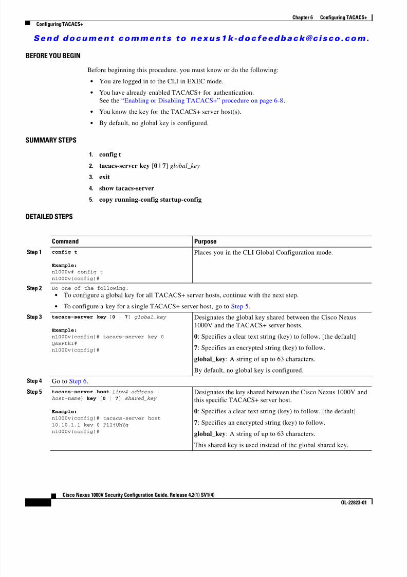
8/13/2019 n1000v Security
http://slidepdf.com/reader/full/n1000v-security 96/234
S e n d d o c u m e n t c o m m e n t s t o n e x u s 1 k - d o c f e e d b a c k @ c i s c o . c o m .
6-10Cisco Nexus 1000V Security Configuration Guide, Release 4.2(1) SV1(4)
OL-22823-01
Chapter 6 Configuring TACACS+Configuring TACACS+
BEFORE YOU BEGIN
Before beginning this procedure, you must know or do the following:
• You are logged in to the CLI in EXEC mode.
• You have already enabled TACACS+ for authentication.
See the “Enabling or Disabling TACACS+” procedure on page 6-8 . • You know the key for the TACACS+ server host(s).
• By default, no global key is configured.
SUMMARY STEPS
1. config t
2. tacacs-server key [0 | 7] global_key
3. exit
4. show tacacs-server
5. copy running-config startup-config
DETAILED STEPS
Command Purpose
Step 1 config t
Example:n1000v# config tn1000v(config)#
Places you in the CLI Global Configuration mode.
Step 2 Do one of the following: • To configure a global key for all TACACS+ server hosts, continue with the next step.
• To configure a key for a s ingle TACACS+ server host, go to Step 5 .
Step 3 tacacs-server key [ 0 | 7] global_key
Example:n1000v(config)# tacacs-server key 0QsEFtkI#n1000v(config)#
Designates the global key shared between the Cisco Nexus1000V and the TACACS+ server hosts.
0: Specifies a clear text string (key) to follow. [the default]
7: Specifies an encrypted string (key) to follow.
global_key : A string of up to 63 characters.
By default, no global key is configured.
Step 4 Go to Step 6 .
Step 5 tacacs-server host { ipv4-address |host-name } key [ 0 | 7] shared_key
Example:n1000v(config)# tacacs-server host10.10.1.1 key 0 PlIjUhYgn1000v(config)#
Designates the key shared between the Cisco Nexus 1000V andthis specific TACACS+ server host.
0: Specifies a clear text string (key) to follow. [the default]
7: Specifies an encrypted string (key) to follow.
global_key : A string of up to 63 characters.
This shared key is used instead of the global shared key.

8/13/2019 n1000v Security
http://slidepdf.com/reader/full/n1000v-security 97/234
S e n d d o c u m e n t c o m m e n t s t o n e x u s 1 k - d o c f e e d b a c k @ c i s c o . c o m .
6-11Cisco Nexus 1000V Security Configuration Guide, Release 4.2(1) SV1(4)
OL-22823-01
Chapter 6 Configuring TACACS+Configuring TACACS+
Configuring a TACACS+ Server HostUse this procedure to configure a TACACS+ server as a TACACS+ host.
BEFORE YOU BEGIN
Before beginning this procedure, you must know or do the following:
• You are logged in to the CLI in EXEC mode.
• You have already enabled TACACS+ for authentication. See the “Enabling or Disabling TACACS+” procedure on page 6-8 .
• You have already configured the shared key, using the following:
“Configuring Shared Keys” procedure on page 6-9
• You know the IP addresses or the hostnames for the remote TACACS+ server hosts.
• All TACACS+ server hosts are added to the default TACACS+ server group.
SUMMARY STEPS
1. config t
2. tacacs-server host {ipv4-address | host-name }
3. exit
4. show tacacs-server
5. copy running-config startup-config
Step 6 exit
Example:n1000v(config)# exitn1000v#
Exits the CLI Global Configuration mode and returns you toEXEC mode.
Step 7 show tacacs-server
Example:n1000v# show tacacs-serverGlobal TACACS+ shared secret:********timeout value:5deadtime value:0total number of servers:1
following TACACS+ servers are configured: 10.10.2.2: available on port:49
(Optional) Displays the TACACS+ server configuration.
Note The global shared key is saved in encrypted form in therunning configuration. To display the key, use the showrunning-config command.
Step 8 copy running-config startup-config
Example:n1000v# copy running-config startup-config
(Optional) Copies these changes in the running configuration tothe startup configuration.
Command Purpose

8/13/2019 n1000v Security
http://slidepdf.com/reader/full/n1000v-security 98/234
S e n d d o c u m e n t c o m m e n t s t o n e x u s 1 k - d o c f e e d b a c k @ c i s c o . c o m .
6-12Cisco Nexus 1000V Security Configuration Guide, Release 4.2(1) SV1(4)
OL-22823-01
Chapter 6 Configuring TACACS+Configuring TACACS+
DETAILED STEPS
Configuring a TACACS+ Server GroupUse this procedure to configure a TACACS+ server group whose member servers share authenticationfunctions.
BEFORE YOU BEGIN
Before beginning this procedure, you must know or do the following: • You are logged in to the CLI in EXEC mode.
• All servers added to a TACACS+ server group must use the TACACS+ protocol.
• Once the TACACS+ server group is configured, the server members are tried in the same order inwhich you configured them.
• You have already enabled TACACS+ for authentication. See the “Enabling or Disabling TACACS+” procedure on page 6-8 .
Command Purpose
Step 1 config t
Example:n1000v# config tn1000v(config)#
Places you in the CLI Global Configuration mode.
Step 2 tacacs-server host { ipv4-address |host-name }
Example:n1000v(config)# tacacs-server host10.10.2.2
Configures the server IP address or hostname as aTACACS+ server host.
Step 3 exit
Example:n1000v(config)# exitn1000v#
Exits the CLI Global Configuration mode and returnsyou to EXEC mode.
Step 4 show tacacs-server
Example:n1000v# show tacacs-server timeout value:5deadtime value:0total number of servers:1
following TACACS+ servers areconfigured: 10.10.2.2: available on port:49n1000v#
(Optional) Displays the TACACS+ serverconfiguration.
Step 5 copy running-config startup-config
Example:n1000v# copy running-configstartup-config
(Optional) Copies these changes in the running
configuration to the startup configuration.

8/13/2019 n1000v Security
http://slidepdf.com/reader/full/n1000v-security 99/234
S e n d d o c u m e n t c o m m e n t s t o n e x u s 1 k - d o c f e e d b a c k @ c i s c o . c o m .
6-13Cisco Nexus 1000V Security Configuration Guide, Release 4.2(1) SV1(4)
OL-22823-01
Chapter 6 Configuring TACACS+Configuring TACACS+
• You have already configured the preshared keys, using the following:
“Configuring Shared Keys” procedure on page 6-9
• A TACACS+ server group can provide fail-over in case one server fails to respond. If the first serverin the group fails, the next server in the group is tried until a server responds. Multiple server groupscan provide fail-over for each other in this same way.
SUMMARY STEPS
1. config t
2. aaa group server tacacs+ group-name
3. server {ipv4-address | host-name }
4. deadtime minutes
5. use-vrf vrf-name
6. (Optional) source-interface {interface-type } {interface-number }
7. (Optional) show tacacs-server groups
8. (Optional) copy running-config startup-config
DETAILED STEPS
Command Purpose
Step 1 config t
Example:n1000v# config tn1000v(config)#
Places you in the CLI Global Configuration mode.
Step 2 aaa group server tacacs+ group-name
Example:n1000v(config)# aaa group server tacacs+TacServern1000v(config-tacacs+)#
Creates a TACACS+ server group with the specified
name and places you into the TACACS+ configurationmode for that group.
Step 3 server { ipv4-address | host-name }
Example:n1000v(config-tacacs+)# server 10.10.2.2n1000v(config-tacacs+)#
Configures the TACACS+ server host-name or IPaddress as a member of the TACACS+ server group.
Tip If the specified TACACS+ server is not found,configure it using the tacacs-server host command and retry this command.
Step 4 deadtime minutes
Example:
n1000v(config-tacacs+)# deadtime 30n1000v(config-tacacs+)#
(Optional) Configures the monitoring dead time forthis TACACS+ group. The default is 0 minutes. Therange is from 0 through 1440.
Note If the dead-time interval for a TACACS+server group is greater than zero (0), that valuetakes precedence over the global dead-timevalue (see the “Configuring the TACACS+Global Dead-Time Interval” procedure onpage 6-21 ).

8/13/2019 n1000v Security
http://slidepdf.com/reader/full/n1000v-security 100/234
S e n d d o c u m e n t c o m m e n t s t o n e x u s 1 k - d o c f e e d b a c k @ c i s c o . c o m .
6-14Cisco Nexus 1000V Security Configuration Guide, Release 4.2(1) SV1(4)
OL-22823-01
Chapter 6 Configuring TACACS+Configuring TACACS+
Example :n1000v(config)# aaa group server tacacs+ TacServern1000v(config-tacacs+)# server 10.10.2.2n1000v(config-tacacs+)# deadtime 30n1000v(config-tacacs+)# use-vrf managementn1000v(config-tacacs+)# show tacacs-server groups total number of groups:1
following TACACS+ server groups are configured: group TacServer: server 10.10.2.2 on port 49 deadtime is 30
vrf is managementn1000v(config-tacacs+)#
Step 5 use-vrf vrf-name
Example:n1000v(config-tacacs+)# use-vrf
managementn1000v(config-tacacs+)#
(Optional) Specifies the virtual routing and forwardinginstance (VRF) to use to contact this server group.
Step 6 source-interface { interface-type } { interface-number }
Example:n1000v(config-tacacs+)# source-interface
mgmt0n1000v(config-tacacs+)#
(Optional) Specifies a source interface to be used toreach the TACACS+ server.
• loopback = Virtual interface number from 0 to1023
• mgmt = Management interface 0
• null = Null interface 0
• port-channel = Port channel number from 1 to4096
Step 7 show tacacs-server groups (Optional) Displays the TACACS+ server group
configuration.Example:n1000v(config-tacacs+)# show tacacs-server groupstotal number of groups:1
following TACACS+ server groups are configured: group TacServer: server 10.10.2.2 on port 49 deadtime is 30 vrf is managementn1000v(config-tacacs+)#
Step 8 copy running-config startup-config
Example:n1000v(config-tacacs+)# copyrunning-config startup-config
(Optional) Copies these changes made in the runningconfiguration to the startup configuration.
Command Purpose
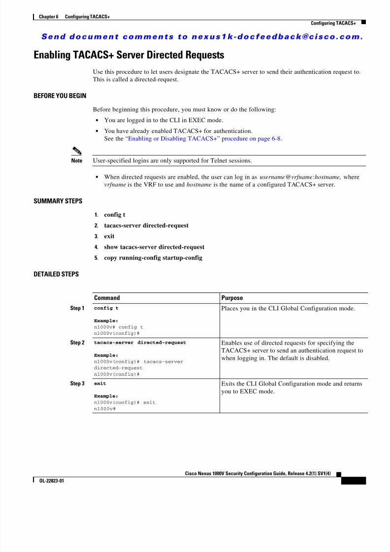
8/13/2019 n1000v Security
http://slidepdf.com/reader/full/n1000v-security 101/234
S e n d d o c u m e n t c o m m e n t s t o n e x u s 1 k - d o c f e e d b a c k @ c i s c o . c o m .
6-15Cisco Nexus 1000V Security Configuration Guide, Release 4.2(1) SV1(4)
OL-22823-01
Chapter 6 Configuring TACACS+Configuring TACACS+
Enabling TACACS+ Server Directed RequestsUse this procedure to let users designate the TACACS+ server to send their authentication request to.This is called a directed-request.
BEFORE YOU BEGINBefore beginning this procedure, you must know or do the following:
• You are logged in to the CLI in EXEC mode.
• You have already enabled TACACS+ for authentication. See the “Enabling or Disabling TACACS+” procedure on page 6-8 .
Note User-specified logins are only supported for Telnet sessions.
• When directed requests are enabled, the user can log in as username @vrfname :hostname, wherevrfname is the VRF to use and hostname is the name of a configured TACACS+ server.
SUMMARY STEPS
1. config t
2. tacacs-server directed-request
3. exit
4. show tacacs-server directed-request
5. copy running-config startup-config
DETAILED STEPS
Command Purpose
Step 1 config t
Example:n1000v# config tn1000v(config)#
Places you in the CLI Global Configuration mode.
Step 2 tacacs-server directed-request
Example:n1000v(config)# tacacs-serverdirected-requestn1000v(config)#
Enables use of directed requests for specifying theTACACS+ server to send an authentication request towhen logging in. The default is disabled.
Step 3 exit
Example:n1000v(config)# exitn1000v#
Exits the CLI Global Configuration mode and returnsyou to EXEC mode.

8/13/2019 n1000v Security
http://slidepdf.com/reader/full/n1000v-security 102/234
S e n d d o c u m e n t c o m m e n t s t o n e x u s 1 k - d o c f e e d b a c k @ c i s c o . c o m .
6-16Cisco Nexus 1000V Security Configuration Guide, Release 4.2(1) SV1(4)
OL-22823-01
Chapter 6 Configuring TACACS+Configuring TACACS+
Setting the TACACS+ Global Timeout IntervalUse this procedure to set the interval in seconds that the Cisco Nexus 1000V waits for a response fromany TACACS+ server before declaring a timeout.
BEFORE YOU BEGIN
Before beginning this procedure, you must know or do the following:
• You are logged in to the CLI in EXEC mode.
• You have already enabled TACACS+ for authentication. See the “Enabling or Disabling TACACS+” procedure on page 6-8 .
• The timeout specified for an individual TACACS+ server overrides the global timeout interval. Toset the timeout for an individual server, see the “Setting a Timeout Interval for an IndividualTACACS+ Host” procedure on page 6-17 .
SUMMARY STEPS1. config t
2. tacacs-server timeout seconds
3. exit
4. show tacacs-server
5. copy running-config startup-config
Step 4 show tacacs-server directed-request
Example:n1000v# show tacacs-serverdirected-requestenabledn1000v#
(Optional) Displays the TACACS+ directed requestconfiguration.
Step 5 copy running-config startup-config
Example:n1000v# copy running-configstartup-config
(Optional) Copies the running configuration to thestartup configuration.
Command Purpose
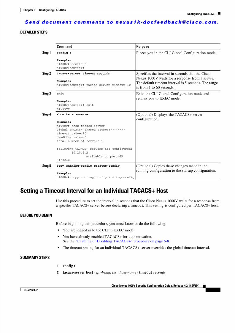
8/13/2019 n1000v Security
http://slidepdf.com/reader/full/n1000v-security 103/234
S e n d d o c u m e n t c o m m e n t s t o n e x u s 1 k - d o c f e e d b a c k @ c i s c o . c o m .
6-17Cisco Nexus 1000V Security Configuration Guide, Release 4.2(1) SV1(4)
OL-22823-01
Chapter 6 Configuring TACACS+Configuring TACACS+
DETAILED STEPS
Setting a Timeout Interval for an Individual TACACS+ HostUse this procedure to set the interval in seconds that the Cisco Nexus 1000V waits for a response froma specific TACACS+ server before declaring a timeout. This setting is configured per TACACS+ host.
BEFORE YOU BEGIN
Before beginning this procedure, you must know or do the following:
• You are logged in to the CLI in EXEC mode.
• You have already enabled TACACS+ for authentication. See the “Enabling or Disabling TACACS+” procedure on page 6-8 .
• The timeout setting for an individual TACACS+ server overrides the global timeout interval.
SUMMARY STEPS
1. config t
2. tacacs-server host {ipv4-address | host-name } timeout seconds
Command Purpose
Step 1 config t
Example:n1000v# config tn1000v(config)#
Places you in the CLI Global Configuration mode.
Step 2 tacacs-server timeout seconds
Example:n1000v(config)# tacacs-server timeout 10
Specifies the interval in seconds that the CiscoNexus 1000V waits for a response from a server.The default timeout interval is 5 seconds. The rangeis from 1 to 60 seconds.
Step 3 exit
Example:n1000v(config)# exitn1000v#
Exits the CLI Global Configuration mode andreturns you to EXEC mode.
Step 4 show tacacs-server
Example:n1000v# show tacacs-serverGlobal TACACS+ shared secret:********timeout value:10deadtime value:0total number of servers:1
following TACACS+ servers are configured: 10.10.2.2: available on port:49n1000v#
(Optional) Displays the TACACS+ serverconfiguration.
Step 5 copy running-config startup-config
Example:n1000v# copy running-config startup-config
(Optional) Copies these changes made in therunning configuration to the startup configuration.
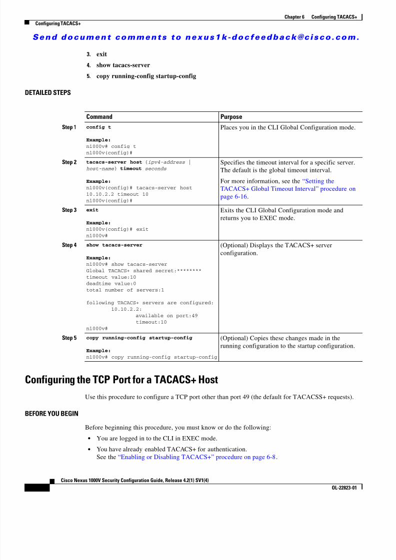
8/13/2019 n1000v Security
http://slidepdf.com/reader/full/n1000v-security 104/234
S e n d d o c u m e n t c o m m e n t s t o n e x u s 1 k - d o c f e e d b a c k @ c i s c o . c o m .
6-18Cisco Nexus 1000V Security Configuration Guide, Release 4.2(1) SV1(4)
OL-22823-01
Chapter 6 Configuring TACACS+Configuring TACACS+
3. exit
4. show tacacs-server
5. copy running-config startup-config
DETAILED STEPS
Configuring the TCP Port for a TACACS+ HostUse this procedure to configure a TCP port other than port 49 (the default for TACACSS+ requests).
BEFORE YOU BEGIN
Before beginning this procedure, you must know or do the following:
• You are logged in to the CLI in EXEC mode.
• You have already enabled TACACS+ for authentication. See the “Enabling or Disabling TACACS+” procedure on page 6-8 .
Command Purpose
Step 1 config t
Example:n1000v# config tn1000v(config)#
Places you in the CLI Global Configuration mode.
Step 2 tacacs-server host { ipv4-address |host-name } timeout seconds
Example:n1000v(config)# tacacs-server host
10.10.2.2 timeout 10n1000v(config)#
Specifies the timeout interval for a specific server.The default is the global timeout interval.
For more information, see the “Setting theTACACS+ Global Timeout Interval” procedure on
page 6-16 .
Step 3 exit
Example:n1000v(config)# exitn1000v#
Exits the CLI Global Configuration mode andreturns you to EXEC mode.
Step 4 show tacacs-server
Example:n1000v# show tacacs-serverGlobal TACACS+ shared secret:********timeout value:10deadtime value:0total number of servers:1
following TACACS+ servers are configured: 10.10.2.2: available on port:49 timeout:10n1000v#
(Optional) Displays the TACACS+ serverconfiguration.
Step 5 copy running-config startup-config
Example:n1000v# copy running-config startup-config
(Optional) Copies these changes made in therunning configuration to the startup configuration.

8/13/2019 n1000v Security
http://slidepdf.com/reader/full/n1000v-security 105/234
S e n d d o c u m e n t c o m m e n t s t o n e x u s 1 k - d o c f e e d b a c k @ c i s c o . c o m .
6-19Cisco Nexus 1000V Security Configuration Guide, Release 4.2(1) SV1(4)
OL-22823-01
Chapter 6 Configuring TACACS+Configuring TACACS+
• You have configured the TACACS+ server using the “Configuring a TACACS+ Server Host”procedure on page 6-11 .
SUMMARY STEPS
1. config t
2. tacacs-server host {ipv4-address | host-name } port tcp-port
3. exit
4. show tacacs-server
5. copy running-config startup-config
DETAILED STEPS
Command Purpose
Step 1 config t
Example:n1000v# config tn1000v(config)#
Places you in the CLI Global Configuration mode.
Step 2 tacacs-server host { ipv4-address |host-name } port tcp-port
Example:n1000v(config)# tacacs-server host10.10.2.2 port 2n1000v(config)#
Specifies the TCP port to use.
allowable range: 1 to 65535
default: 49
Step 3 exit
Example:n1000v(config)# exitn1000v#
Exits the CLI Global Configuration mode andreturns you to EXEC mode.
Step 4 show tacacs-server
Example:n1000v# show tacacs-serverGlobal TACACS+ shared secret:********timeout value:10deadtime value:0total number of servers:1
following TACACS+ servers are configured: 10.10.2.2: available on port:2 timeout:10n1000v#
(Optional) Displays the TACACS+ serverconfiguration.
Step 5 copy running-config startup-config
Example:n1000v# copy running-config startup-config
(Optional) Copies the running configuration to thestartup configuration.

8/13/2019 n1000v Security
http://slidepdf.com/reader/full/n1000v-security 106/234
S e n d d o c u m e n t c o m m e n t s t o n e x u s 1 k - d o c f e e d b a c k @ c i s c o . c o m .
6-20Cisco Nexus 1000V Security Configuration Guide, Release 4.2(1) SV1(4)
OL-22823-01
Chapter 6 Configuring TACACS+Configuring TACACS+
Configuring Monitoring for a TACACS+ HostUse this procedure to configure periodic monitoring of a TACACS+ host.
BEFORE YOU BEGIN
Before starting this procedure, you must know or do the following:
• You are logged in to the CLI in EXEC mode.
• You have already enabled TACACS+ for authentication. See the “Enabling or Disabling TACACS+” procedure on page 6-8 .
• You have configured the TACACS+ server. See the “Configuring a TACACS+ Server Host” procedure on page 6-11 .
• The idle timer specifies how long a TACACS+ server should remain idle (receiving no requests)before sending it a test packet.
• The default idle timer value is 0 minutes. When the idle time interval is 0 minutes, periodicTACACS+ server monitoring is not done.
SUMMARY STEPS
1. config t
2. tacacs-server host {ipv4-address | host-name } test {idle-time minutes | password password[idle-time minutes ] | username name [password password [idle-time minutes ]]}
3. tacacs-server dead-time minutes
4. exit
5. show tacacs-server
6. copy running-config startup-config
DETAILED STEPS
Command Purpose
Step 1 config t
Example:n1000v# config tn1000v(config)#
Places you in the CLI Global Configuration mode.
Step 2 tacacs-server host { ipv4-address |host-name } test { idle-time minutes |
password password [ idle-time minutes ] | username name [ password password
[ idle-time minutes ]]}
Example:n1000v(config)# tacacs-server host10.10.2.2 test username pvk2 passworda3z9yjqz7 idle-time 3
Configures server monitoring.
username : The default is test.
Note To protect network security, we recommendassigning a username that is not already inthe TACACS+ database.
password : The default is test.
idle-time : The default is 0 minutes. The valid rangeis from 0 to 1440 minutes.
Note For periodic TACACS+ server monitoring,the idle timer value must be greater than 0.

8/13/2019 n1000v Security
http://slidepdf.com/reader/full/n1000v-security 107/234
S e n d d o c u m e n t c o m m e n t s t o n e x u s 1 k - d o c f e e d b a c k @ c i s c o . c o m .
6-21Cisco Nexus 1000V Security Configuration Guide, Release 4.2(1) SV1(4)
OL-22823-01
Chapter 6 Configuring TACACS+Configuring TACACS+
Configuring the TACACS+ Global Dead-Time IntervalUse this procedure to configure the interval to wait before sending a test packet to a previouslyunresponsive server.
BEFORE YOU BEGIN
Before starting this procedure, you must know or do the following:
• You are logged in to the CLI in EXEC mode.
• You have already enabled TACACS+ for authentication. See the “Enabling or Disabling TACACS+” procedure on page 6-8 .
• You have configured the TACACS+ server. See the “Configuring a TACACS+ Server Host” procedure on page 6-11 .
• When the dead-timer interval is 0 minutes, TACACS+ servers are not marked as dead even if they
are not responding. You can configure the dead-timer per group (see the “Configuring a TACACS+Server Group” procedure on page 6-12 ).
SUMMARY STEPS
1. config t
2. tacacs-server deadtime minutes
3. exit
Step 3 tacacs-server dead-time minutes
Example:n1000v(config)# tacacs-server dead-time 5
Specifies the duration of time in minutes beforechecking a TACACS+ server that was previouslyunresponsive. The default value is 0 minutes and thevalid range is from 0 to 1440 minutes.
Step 4 exit
Example:n1000v(config)# exitn1000v#
Exits the CLI Global Configuration mode andreturns you to EXEC mode.
Step 5 show tacacs-server
Example:n1000v# show tacacs-serverGlobal TACACS+ shared secret:********timeout value:10deadtime value:0total number of servers:1
following TACACS+ servers are configured: 10.10.2.2: available on port:2 timeout:10n1000v#
(Optional) Displays the TACACS+ serverconfiguration.
Step 6 copy running-config startup-config
Example:n1000v# copy running-config startup-config
(Optional) Copies these changes made to therunning configuration to the startup configuration.
Command Purpose

8/13/2019 n1000v Security
http://slidepdf.com/reader/full/n1000v-security 108/234
S e n d d o c u m e n t c o m m e n t s t o n e x u s 1 k - d o c f e e d b a c k @ c i s c o . c o m .
6-22Cisco Nexus 1000V Security Configuration Guide, Release 4.2(1) SV1(4)
OL-22823-01
Chapter 6 Configuring TACACS+Displaying Statistics for a TACACS+ Host
4. show tacacs-server
5. copy running-config startup-config
DETAILED STEPS
Displaying Statistics for a TACACS+ HostUse this procedure to display the statistics for TACACS+ host.
BEFORE YOU BEGIN
Before starting this procedure, you must know or do the following:
• You are logged in to the CLI in EXEC mode.
• You have already enabled TACACS+ for authentication. See the “Enabling or Disabling TACACS+” procedure on page 6-8 .
• You have configured the TACACS+ server.
See the “Configuring a TACACS+ Server Host” procedure on page 6-11 .
SUMMARY STEPS
1. show tacacs-server statistics {hostname | ipv4-address }
Command Purpose
Step 1 config t
Example:n1000v# config tn1000v(config)#
Places you in the CLI Global Configuration mode.
Step 2 tacacs-server deadtime minutes
Example:n1000v(config)# tacacs-server deadtime 5
Configures the global dead-time interval. The defaultvalue is 0 minutes. The range is from 1 to 1440 minutes
Step 3 exit
Example:n1000v(config)# exitn1000v#
Exits the CLI Global Configuration mode and returnsyou to EXEC mode.
Step 4 show tacacs-server
Example:n1000v# show tacacs-server
(Optional) Displays the TACACS+ serverconfiguration.
Step 5 copy running-config startup-config
Example:n1000v# copy running-configstartup-config
(Optional) Copies the running configuration to thestartup configuration.
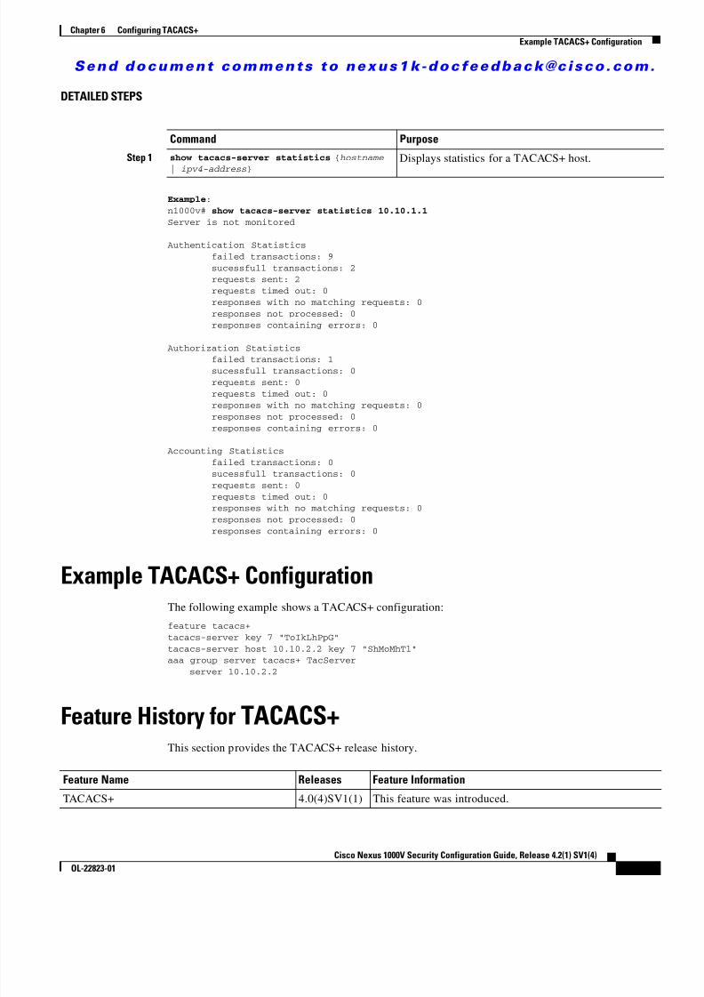
8/13/2019 n1000v Security
http://slidepdf.com/reader/full/n1000v-security 109/234
S e n d d o c u m e n t c o m m e n t s t o n e x u s 1 k - d o c f e e d b a c k @ c i s c o . c o m .
6-23Cisco Nexus 1000V Security Configuration Guide, Release 4.2(1) SV1(4)
OL-22823-01
Chapter 6 Configuring TACACS+Example TACACS+ Configuration
DETAILED STEPS
Example :n1000v# show tacacs-server statistics 10.10.1.1Server is not monitored
Authentication Statistics failed transactions: 9 sucessfull transactions: 2 requests sent: 2 requests timed out: 0 responses with no matching requests: 0 responses not processed: 0 responses containing errors: 0
Authorization Statistics failed transactions: 1 sucessfull transactions: 0 requests sent: 0 requests timed out: 0 responses with no matching requests: 0 responses not processed: 0 responses containing errors: 0
Accounting Statistics failed transactions: 0 sucessfull transactions: 0 requests sent: 0 requests timed out: 0 responses with no matching requests: 0
responses not processed: 0 responses containing errors: 0
Example TACACS+ ConfigurationThe following example shows a TACACS+ configuration:
feature tacacs+tacacs-server key 7 "ToIkLhPpG"tacacs-server host 10.10.2.2 key 7 "ShMoMhTl"aaa group server tacacs+ TacServer server 10.10.2.2
Feature History for TACACS+This section provides the TACACS+ release history.
Command Purpose
Step 1 show tacacs-server statistics {hostname | ipv4-address }
Displays statistics for a TACACS+ host.
Feature Name Releases Feature Information
TACACS+ 4.0(4)SV1(1) This feature was introduced.

8/13/2019 n1000v Security
http://slidepdf.com/reader/full/n1000v-security 110/234
S e n d d o c u m e n t c o m m e n t s t o n e x u s 1 k - d o c f e e d b a c k @ c i s c o . c o m .
6-24Cisco Nexus 1000V Security Configuration Guide, Release 4.2(1) SV1(4)
OL-22823-01
Chapter 6 Configuring TACACS+Additional References
Additional ReferencesFor additional information related to implementing TACACS+, see the following sections:
• Related Documents, page 6-24
• Standards, page 6-24
Related Documents
Standards
Related Topic Document Title
CLI Cisco Nexus 1000V Command Reference, Release 4.2(1)SV1(4)
System Management Cisco Nexus 1000V System Management Configuration Guide, Release4.2(1)SV1(4)
Standards Title
No new or modified standards are supported by thisfeature, and support for existing standards has not beenmodified by this feature.
—
8/13/2019 n1000v Security
http://slidepdf.com/reader/full/n1000v-security 111/234
C H A P T E R
S e n d d o c u m e n t c o m m e n t s t o n e x u s 1 k - d o c f e e d b a c k @ c i s c o . c o m .
7-1Cisco Nexus 1000V Security Configuration Guide, Release 4.2(1) SV1(4)
OL-22823-01
7Configuring SSH
This chapter describes how to configure Secure Shell Protocol (SSH).
This chapter includes the following sections:
• Information About SSH, page 7-1
• Prerequisites for SSH, page 7-2
• Guidelines and Limitations, page 7-2
• Default Settings, page 7-3
• Configuring SSH, page 7-3
• Verifying the SSH Configuration, page 7-13
• SSH Example Configuration, page 7-14
• Additional References, page 7-15
• Feature History for SSH, page 7-15
Information About SSHThis section includes the following topics:
• SSH Server, page 7-1
• SSH Client, page 7-2
• SSH Server Keys, page 7-2
SSH ServerYou can use the SSH server to enable an SSH client to make a secure, encrypted connection. SSH usesstrong encryption for authentication. The SSH server can operate with publicly and commerciallyavailable SSH clients.
TACACS+ user authentication and locally stored user names and passwords is supported for SSH.

8/13/2019 n1000v Security
http://slidepdf.com/reader/full/n1000v-security 112/234
S e n d d o c u m e n t c o m m e n t s t o n e x u s 1 k - d o c f e e d b a c k @ c i s c o . c o m .
7-2Cisco Nexus 1000V Security Configuration Guide, Release 4.2(1) SV1(4)
OL-22823-01
Chapter 7 Configuring SSHPrerequisites for SSH
SSH ClientThe SSH client feature is an application that runs over the SSH protocol to provide device authenticationand encryption. The SSH client enables a secure, encrypted connection to any device that runs the SSHserver. This connection provides an encrypted outbound connection. With authentication and encryption,
the SSH client produces secure communication over an insecure network.The SSH client works with publicly and commercially available SSH servers.
SSH Server KeysSSH requires server keys for secure communication. You can use SSH server keys for the following SSHoptions:
• SSH version 2 using Rivest, Shamir, and Adelman (RSA) public-key cryptography
• SSH version 2 using the Digital System Algrorithm (DSA)
Be sure to have an SSH server key-pair with the correct version before enabling the SSH service.
Generate the SSH server key-pair according to the SSH client version used. The SSH service accepts twotypes of key-pairs for use by SSH version 2:
• The dsa option generates the DSA key-pair for the SSH version 2 protocol.
• The rsa option generates the RSA key-pair for the SSH version 2 protocol.
By default, an RSA key using 1024 bits is generated.
SSH supports the following public key formats:
• OpenSSH
• IETF Secure Shell (SECSH)
• Public Key Certificate in Privacy-Enhanced Mail (PEM)
Caution If you delete all of the SSH keys, you cannot start the SSH services.
Prerequisites for SSHSSH has the following prerequisite:
• You have configured IP on a Layer 3 interface, out-of-band on the mgmt 0 interface, or inband onan Ethernet interface.
• Before enabling the SSH server, obtain the SSH key.
Guidelines and Limitations • Only SSH version 2 (SSHv2) is supported.
• SSH is enabled by default.
• Cisco NX-OS commands might differ from the Cisco IOS commands.

8/13/2019 n1000v Security
http://slidepdf.com/reader/full/n1000v-security 113/234
S e n d d o c u m e n t c o m m e n t s t o n e x u s 1 k - d o c f e e d b a c k @ c i s c o . c o m .
7-3Cisco Nexus 1000V Security Configuration Guide, Release 4.2(1) SV1(4)
OL-22823-01
Chapter 7 Configuring SSHDefault Settings
Default SettingsThe following table lists the default settings for SSH.
Configuring SSHThis section includes the following topics:
• Generating SSH Server Keys, page 7-3
• Configuring a User Account with a Public Key, page 7-5
• Starting SSH Sessions, page 7-8
• Clearing SSH Hosts, page 7-9
• Disabling the SSH Server, page 7-9
• Deleting SSH Server Keys, page 7-10
• Clearing SSH Sessions, page 7-12
Generating SSH Server KeysUse this procedure to generate an SSH server key based on your security requirements.
BEFORE YOU BEGIN
Before beginning this procedure, you must know or do the following:
• You are logged in to the CLI in EXEC mode.
• The default SSH server key is an RSA key that is generated using 1024 bits.
SUMMARY STEPS
1. config t
2. no feature ssh
3. ssh key {dsa [force ] | rsa [bits [force ]]}4. feature ssh
5. exit
6. show ssh key
7. copy running-config startup-config
Parameters Default
SSH server Enabled.
SSH server key RSA key generated with 1024 bits.
RSA key bits for generation 1024.
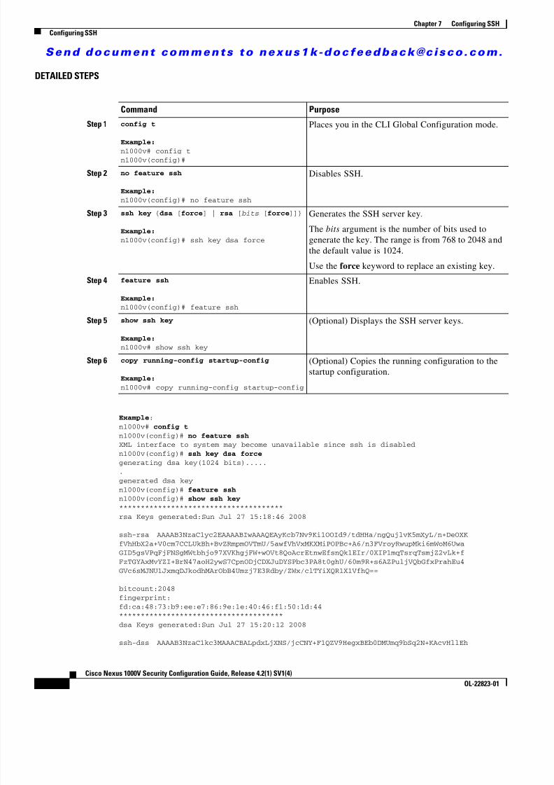
8/13/2019 n1000v Security
http://slidepdf.com/reader/full/n1000v-security 114/234
S e n d d o c u m e n t c o m m e n t s t o n e x u s 1 k - d o c f e e d b a c k @ c i s c o . c o m .
7-4Cisco Nexus 1000V Security Configuration Guide, Release 4.2(1) SV1(4)
OL-22823-01
Chapter 7 Configuring SSHConfiguring SSH
DETAILED STEPS
Example :n1000v# config tn1000v(config)# no feature sshXML interface to system may become unavailable since ssh is disabledn1000v(config)# ssh key dsa forcegenerating dsa key(1024 bits)......generated dsa keyn1000v(config)# feature sshn1000v(config)# show ssh key**************************************rsa Keys generated:Sun Jul 27 15:18:46 2008
ssh-rsa AAAAB3NzaC1yc2EAAAABIwAAAQEAyKcb7Nv9Ki1OOId9/tdHHa/ngQujlvK5mXyL/n+DeOXKfVhHbX2a+V0cm7CCLUkBh+BvZRmpmOVTmU/5awfVhVxMKXMiPOPBc+A6/n3FVroyRwupMki6mWoM6UwaGID5gsVPqFjFNSgMWtbhjo97XVKhgjFW+wOVt8QoAcrEtnwEfsnQk1EIr/0XIP1mqTsrqTsmjZ2vLk+fFzTGYAxMvYZI+BrN47aoH2ywS7CpnODjCDXJuDYSPbc3PA8t0ghU/60m9R+s6AZPuljVQbGfxPrahEu4GVc6sMJNU1JxmqDJkodhMArObB4Umzj7E3Rdby/ZWx/clTYiXQR1X1VfhQ==
bitcount:2048fingerprint:fd:ca:48:73:b9:ee:e7:86:9e:1e:40:46:f1:50:1d:44**************************************dsa Keys generated:Sun Jul 27 15:20:12 2008
ssh-dss AAAAB3NzaC1kc3MAAACBALpdxLjXNS/jcCNY+F1QZV9HegxBEb0DMUmq9bSq2N+KAcvHllEh
Command Purpose
Step 1 config t
Example:n1000v# config tn1000v(config)#
Places you in the CLI Global Configuration mode.
Step 2 no feature ssh
Example:n1000v(config)# no feature ssh
Disables SSH.
Step 3 ssh key { dsa [ force ] | rsa [ bits [ force ]]}
Example:n1000v(config)# ssh key dsa force
Generates the SSH server key .
The bits argument is the number of bits used togenerate the key. The range is from 768 to 2048 andthe default value is 1024.
Use the force keyword to replace an existing key.
Step 4 feature ssh
Example:n1000v(config)# feature ssh
Enables SSH.
Step 5 show ssh key
Example:n1000v# show ssh key
(Optional) Displays the SSH server keys.
Step 6 copy running-config startup-config
Example:n1000v# copy running-config startup-config
(Optional) Copies the running configuration to thestartup configuration.

8/13/2019 n1000v Security
http://slidepdf.com/reader/full/n1000v-security 115/234

8/13/2019 n1000v Security
http://slidepdf.com/reader/full/n1000v-security 116/234
S e n d d o c u m e n t c o m m e n t s t o n e x u s 1 k - d o c f e e d b a c k @ c i s c o . c o m .
7-6Cisco Nexus 1000V Security Configuration Guide, Release 4.2(1) SV1(4)
OL-22823-01
Chapter 7 Configuring SSHConfiguring SSH
DETAILED STEPS
Command Purpose
Step 1 config t
Example:n1000v# config tn1000v(config)#
Places you in the CLI Global Configuration
mode.
Step 2 username username sshkey ssh-key Configures the SSH public key in OpenSSHformat with an exiting user account.
To create a user account use the followingcommand:
username name password pwd
Example:n1000v(config)# username user1 sshkey ssh-rsa AAAAB3NzaC1yc2EAAAABIwAAAQEAyKcb7Nv9Ki1OOId9/tdHHa/ngQujlvK5mXyL/n+DeOXKfVhHbX2a+V0cm7CCLUkBh+BvZRmpmOVTmU/5awfVhVxMKXMiPOPBc+A6/n3FVroyRwupMki6mWoM6UwaGID5gsVPqFjFNSgMWtbhjo97XVKhgjFW+wOVt8QoAcrEtnwEfsnQk1EIr/0XIP1mqTsrqTsmjZ2vLk+fFzTGYAxMvYZI+BrN47aoH2ywS7CpnODjCDXJuDYSPbc3PA8t0ghU/60m9R+s6AZPuljVQbGfxPrahEu4GVc6sMJNU1JxmqDJkodhMArObB4Umzj7E3Rdby/ZWx/clTYiXQR1X1VfhQ==
Step 3 exit
Example:n1000v(config)# exitn1000v#
Exits Global Configuration mode and returnsyou to EXEC mode.
Step 4 show user-account (Optional) Displays the user accountconfiguration.
Example:n1000v# show user-accountuser:admin
this user account has no expiry date roles:network-adminuser:user1 this user account has no expiry date roles:network-operator ssh public key: ssh-rsa AAAAB3NzaC1yc2EAAAABIwAAAQEAyKcb7Nv9Ki1OOId9/tdHHa/ngQujlvK5mXyL/n+DeOXKfVhHbX2a+V0cm7CCLUkBh+BvZRmpmOVTmU/5awfVhVxMKXMiPOPBc+A6/n3FVroyRwupMki6mWoM6UwaGID5gsVPqFjFNSgMWtbhjo97XVKhgjFW+wOVt8QoAcrEtnwEfsnQk1EIr/0XIP1mqTsrqTsmjZ2vLk+fFzTGYAxMvYZI+BrN47aoH2ywS7CpnODjCDXJuDYSPbc3PA8t0ghU/60m 9R+s6AZPuljVQbGfxPrahEu4GVc6sMJNU1JxmqDJkodhMArObB4Umzj7E3Rdby/ZWx/clTYiXQR1X1VfhQ==
Step 5 copy running-config startup-config
Example:n1000v# copy running-config startup-config
(Optional) Copies the running configuration tothe startup configuration.

8/13/2019 n1000v Security
http://slidepdf.com/reader/full/n1000v-security 117/234
S e n d d o c u m e n t c o m m e n t s t o n e x u s 1 k - d o c f e e d b a c k @ c i s c o . c o m .
7-7Cisco Nexus 1000V Security Configuration Guide, Release 4.2(1) SV1(4)
OL-22823-01
Chapter 7 Configuring SSHConfiguring SSH
Configuring IETF or PEM Keys
Use this procedure to specify the SSH public keys in IETF SECSH or PEM format for user accounts.
BEFORE YOU BEGIN
Before beginning this procedure, you must know or do the following:
• You are logged in to the CLI in EXEC mode.
• You have already generated an SSH public key in one of the following formats: – IETF SECSH format – Public Key Certificate in PEM format
SUMMARY STEPS
1. copy server-file bootflash: filename
2. config t
3. username username sshkey file bootflash: filename4. exit
5. show user-account
6. copy running-config startup-config
DETAILED STEPS
Command Purpose
Step 1 copy server-file bootflash: filename Downloads the file containing the SSH keyfrom a server. The server can be FTP, securecopy (SCP), secure FTP (SFTP), or TFTP.
Example:n1000v# copy tftp://10.78.1.10/secsh_file.pub bootflash:secsh_file.pub vrf managementTrying to connect to tftp server......Connection to server Established.|TFTP get operation was successfuln1000v#
Step 2 config t
Example:n1000v# config tn1000v(config)#
Places you in the CLI Global Configurationmode.
Step 3 username username sshkey filebootflash: filename
Example:n1000v(config)# username User1 sshkey filebootflash:secsh_file.pub
Configures the SSH public key.
Step 4 exit
Example:n1000v(config)# exitn1000v#
Exits Global Configuration mode and returnsyou to EXEC mode.

8/13/2019 n1000v Security
http://slidepdf.com/reader/full/n1000v-security 118/234
S e n d d o c u m e n t c o m m e n t s t o n e x u s 1 k - d o c f e e d b a c k @ c i s c o . c o m .
7-8Cisco Nexus 1000V Security Configuration Guide, Release 4.2(1) SV1(4)
OL-22823-01
Chapter 7 Configuring SSHConfiguring SSH
Starting SSH SessionsUse this procedure to start SSH sessions using IP to connect to remote devices.
BEFORE YOU BEGIN
Before beginning this procedure, you must know or do the following:
• You are logged in to the CLI in EXEC mode.
• You have already obtained the hostname and, if needed, the username, for the remote device.
• The SSH server is already enabled on the remote device.
SUMMARY STEPS
1. ssh [username @ ]{hostname | username @hostname } [vrf vrf-name ]
ssh6 [username @ ]{hostname | username @hostname } [vrf vrf-name ]
DETAILED STEPS
Step 5 show user-account (Optional) Displays the user accountconfiguration.
Example:n1000v# show user-account
user:admin this user account has no expiry date roles:network-adminuser:user2 this user account has no expiry date roles:network-operator
ssh public key: ssh-rsaAAAAB3NzaC1yc2EAAAABIwAAAQEAyKcb7Nv9Ki1OOId9/tdHHa/ngQujlvK5mXyL/n+DeOXKfVhHbX2a+V0cm7CCLUkBh+BvZRmpmOVTmU/5awfVhVxMKXMiPOPBc+A6/n3FVroyRwupMki6
mWoM6UwaGID5gsVPqFjFNSgMWtbhjo97XVKhgjFW+wOVt8QoAcrEtnwEfsnQk1EIr/0XIP1mqTsrqTsmjZ2vLk+fFzTGYAxMvYZI+BrN47aoH2ywS7CpnODjCDXJuDYSPbc3PA8t0ghU/60m9R+s6AZPuljVQbGfxPrahEu4GVc6sMJNU1JxmqDJkodhMArObB4Umzj7E3Rdby/ZWx/clTYiXQR1X1VfhQ==
Step 6 copy running-config startup-config
Example:n1000v# copy running-config startup-config
(Optional) Copies the running configuration tothe startup configuration.
Command Purpose
Command Purpose
Step 1 ssh [root@]{ ip address | hostname } [ vrfvrf-name ]
Example:n1000v(config)# ssh [email protected]@172.28.30.77's password:Last login: Sat Jul 26 11:07:23 2008 from171.70.209.64
Creates an SSH IP session to a remote device usingIP. The default VRF is the default VRF.
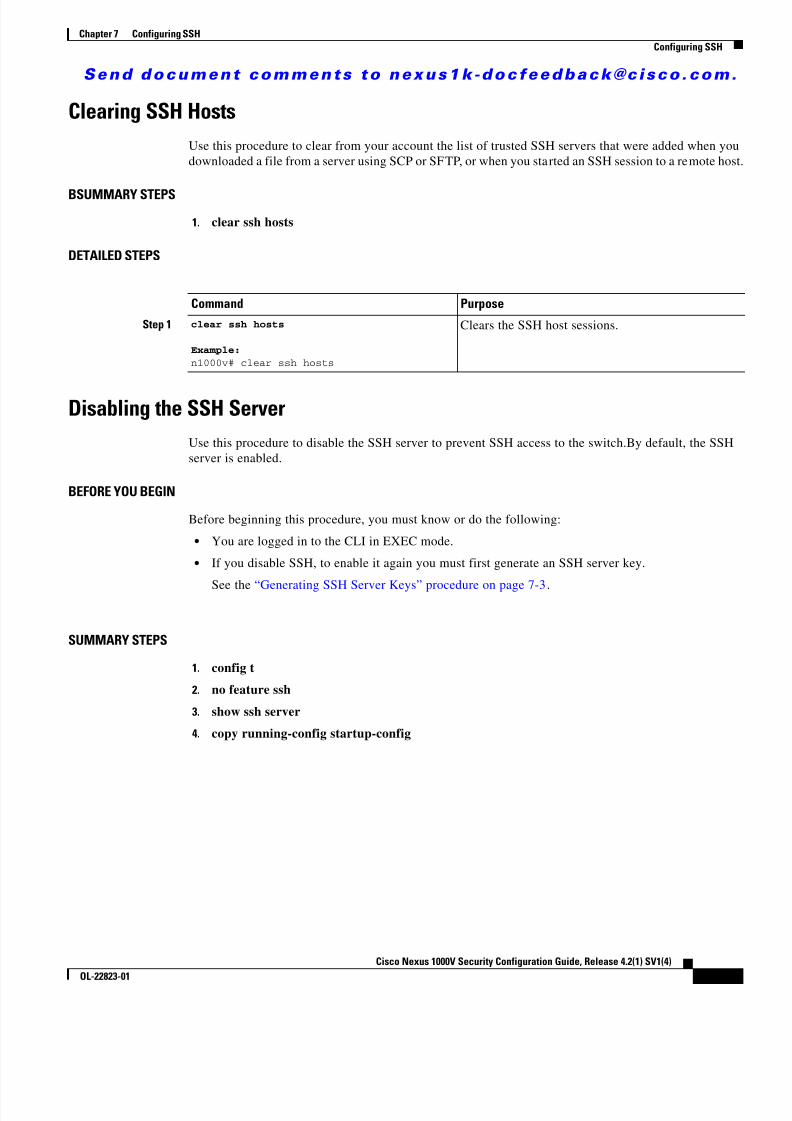
8/13/2019 n1000v Security
http://slidepdf.com/reader/full/n1000v-security 119/234
S e n d d o c u m e n t c o m m e n t s t o n e x u s 1 k - d o c f e e d b a c k @ c i s c o . c o m .
7-9Cisco Nexus 1000V Security Configuration Guide, Release 4.2(1) SV1(4)
OL-22823-01
Chapter 7 Configuring SSHConfiguring SSH
Clearing SSH HostsUse this procedure to clear from your account the list of trusted SSH servers that were added when youdownloaded a file from a server using SCP or SFTP, or when you started an SSH session to a remote host.
BSUMMARY STEPS1. clear ssh hosts
DETAILED STEPS
Disabling the SSH ServerUse this procedure to disable the SSH server to prevent SSH access to the switch.By default, the SSHserver is enabled.
BEFORE YOU BEGIN
Before beginning this procedure, you must know or do the following:
• You are logged in to the CLI in EXEC mode.
• If you disable SSH, to enable it again you must first generate an SSH server key.
See the “Generating SSH Server Keys” procedure on page 7-3 .
SUMMARY STEPS
1. config t
2. no feature ssh
3. show ssh server
4. copy running-config startup-config
Command Purpose
Step 1 clear ssh hosts
Example:n1000v# clear ssh hosts
Clears the SSH host sessions.

8/13/2019 n1000v Security
http://slidepdf.com/reader/full/n1000v-security 120/234
S e n d d o c u m e n t c o m m e n t s t o n e x u s 1 k - d o c f e e d b a c k @ c i s c o . c o m .
7-10Cisco Nexus 1000V Security Configuration Guide, Release 4.2(1) SV1(4)
OL-22823-01
Chapter 7 Configuring SSHConfiguring SSH
DETAILED STEPS
Deleting SSH Server KeysUse this procedure to delete SSH server keys after you disable the SSH server.
BEFORE YOU BEGIN
Before beginning this procedure, you must know or do the following:
• You are logged in to the CLI in EXEC mode.
• If you disable SSH, to enable it again you must first generate an SSH server key.
See the “Generating SSH Server Keys” procedure on page 7-3 .
SUMMARY STEPS
1. config t
2. no feature ssh
3. no ssh key [dsa | rsa ]4. show ssh key
5. copy running-config startup-config
Command Purpose
Step 1 config t
Example:n1000v# config tn1000v(config)#
Places you in the CLI Global Configuration mode.
Step 2 no feature ssh
Example:n1000v(config)# no feature sshXML interface to system may becomeunavailable since ssh is disabledn1000v(config)#
Disables the SSH server. The default is enabled.
Step 3 show ssh server
Example:n1000v(config)# show ssh serverssh is not enabledn1000v(config)#
(Optional) Displays the SSH server configuration.
Step 4 copy running-config startup-config
Example:n1000v(config)# copy running-configstartup-config
(Optional) Copies the running configuration to thestartup configuration.
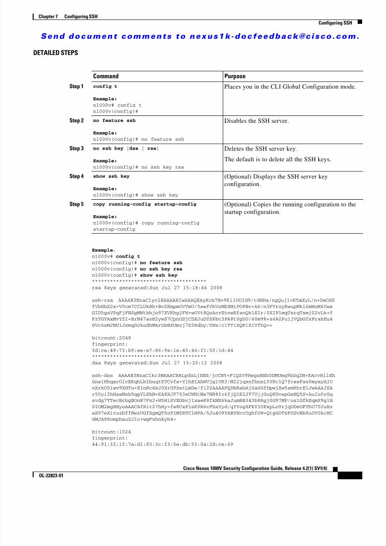
8/13/2019 n1000v Security
http://slidepdf.com/reader/full/n1000v-security 121/234
S e n d d o c u m e n t c o m m e n t s t o n e x u s 1 k - d o c f e e d b a c k @ c i s c o . c o m .
7-11Cisco Nexus 1000V Security Configuration Guide, Release 4.2(1) SV1(4)
OL-22823-01
Chapter 7 Configuring SSHConfiguring SSH
DETAILED STEPS
Example :n1000v# config tn1000v(config)# no feature sshn1000v(config)# no ssh key rsan1000v(config)# show ssh key**************************************rsa Keys generated:Sun Jul 27 15:18:46 2008
ssh-rsa AAAAB3NzaC1yc2EAAAABIwAAAQEAyKcb7Nv9Ki1OOId9/tdHHa/ngQujlvK5mXyL/n+DeOXKfVhHbX2a+V0cm7CCLUkBh+BvZRmpmOVTmU/5awfVhVxMKXMiPOPBc+A6/n3FVroyRwupMki6mWoM6UwaGID5gsVPqFjFNSgMWtbhjo97XVKhgjFW+wOVt8QoAcrEtnwEfsnQk1EIr/0XIP1mqTsrqTsmjZ2vLk+fFzTGYAxMvYZI+BrN47aoH2ywS7CpnODjCDXJuDYSPbc3PA8t0ghU/60m9R+s6AZPuljVQbGfxPrahEu4GVc6sMJNU1JxmqDJkodhMArObB4Umzj7E3Rdby/ZWx/clTYiXQR1X1VfhQ==
bitcount:2048fingerprint:fd:ca:48:73:b9:ee:e7:86:9e:1e:40:46:f1:50:1d:44**************************************dsa Keys generated:Sun Jul 27 15:20:12 2008
ssh-dss AAAAB3NzaC1kc3MAAACBALpdxLjXNS/jcCNY+F1QZV9HegxBEb0DMUmq9bSq2N+KAcvHllEh
GnaiHhqarOlcEKqhLbIbuqtKTCvfa+Y1hBIAhWVjg1UR3/M22jqxnfhnxL5YRc1Q7fcesFax0myayAIUnXrkO5iwv9XHTu+EInRc4kJ0XrG9SxtLmDe/fi2ZAAAAFQDbRabAjZa6GfDpwjXw5smRhrElJwAAAIEAr50yi3hHawNnb5qgYLXhN+KA8XJF753eCWHtMw7NR8fz6fjQ1R2J97UjjGuQ8DvwpGeNQ5S+AuIo0rGqsvdg7TTecBcbgBOnR7Fs2+W5HiSVEGbvj1xaeK8fkNE6kaJumBB343b8Rgj0G97MP/os1GfkEqmX9glB0IOM2mgHHyoAAACAfRir27hHy+fw8CxPlsK0R6cFhxYyd/qYYogXFKYIOPxpLoYrjqODeOFThU7TJuBzaS97eXiruzbffHwzUGfXgmQT5o9IMZRTClWPA/5Ju4O9YABYHccUghf0W+QtgGOT6FOSvBh8uOV0kcHCGMJAP8omphauZJlc+wgFxhnkyh4=
bitcount:1024fingerprint:44:91:32:1f:7a:d1:83:3c:f3:5e:db:53:0a:2d:ce:69
Command Purpose
Step 1 config t
Example:n1000v# config tn1000v(config)#
Places you in the CLI Global Configuration mode.
Step 2 no feature ssh
Example:n1000v(config)# no feature ssh
Disables the SSH server.
Step 3 no ssh key [ dsa | rsa ]
Example:n1000v(config)# no ssh key rsa
Deletes the SSH server key .
The default is to delete all the SSH keys.
Step 4 show ssh key
Example:n1000v(config)# show ssh key
(Optional) Displays the SSH server keyconfiguration.
Step 5 copy running-config startup-config
Example:n1000v(config)# copy running-configstartup-config
(Optional) Copies the running configuration to thestartup configuration.
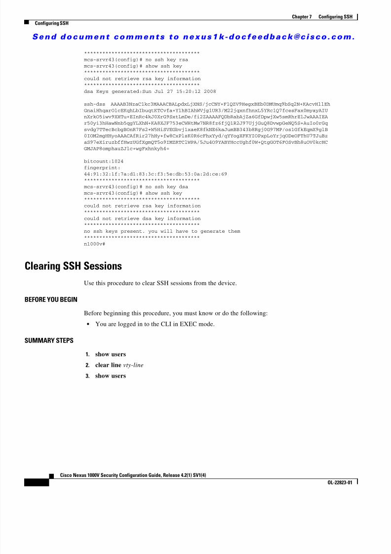
8/13/2019 n1000v Security
http://slidepdf.com/reader/full/n1000v-security 122/234
S e n d d o c u m e n t c o m m e n t s t o n e x u s 1 k - d o c f e e d b a c k @ c i s c o . c o m .
7-12Cisco Nexus 1000V Security Configuration Guide, Release 4.2(1) SV1(4)
OL-22823-01
Chapter 7 Configuring SSHConfiguring SSH
************************************** mcs-srvr43(config)# no ssh key rsa mcs-srvr43(config)# show ssh key
**************************************could not retrieve rsa key information**************************************dsa Keys generated:Sun Jul 27 15:20:12 2008
ssh-dss AAAAB3NzaC1kc3MAAACBALpdxLjXNS/jcCNY+F1QZV9HegxBEb0DMUmq9bSq2N+KAcvHllEhGnaiHhqarOlcEKqhLbIbuqtKTCvfa+Y1hBIAhWVjg1UR3/M22jqxnfhnxL5YRc1Q7fcesFax0myayAIUnXrkO5iwv9XHTu+EInRc4kJ0XrG9SxtLmDe/fi2ZAAAAFQDbRabAjZa6GfDpwjXw5smRhrElJwAAAIEAr50yi3hHawNnb5qgYLXhN+KA8XJF753eCWHtMw7NR8fz6fjQ1R2J97UjjGuQ8DvwpGeNQ5S+AuIo0rGqsvdg7TTecBcbgBOnR7Fs2+W5HiSVEGbvj1xaeK8fkNE6kaJumBB343b8Rgj0G97MP/os1GfkEqmX9glB0IOM2mgHHyoAAACAfRir27hHy+fw8CxPlsK0R6cFhxYyd/qYYogXFKYIOPxpLoYrjqODeOFThU7TJuBzaS97eXiruzbffHwzUGfXgmQT5o9IMZRTClWPA/5Ju4O9YABYHccUghf0W+QtgGOT6FOSvBh8uOV0kcHCGMJAP8omphauZJlc+wgFxhnkyh4=
bitcount:1024fingerprint:44:91:32:1f:7a:d1:83:3c:f3:5e:db:53:0a:2d:ce:69**************************************
mcs-srvr43(config)# no ssh key dsa
mcs-srvr43(config)# show ssh key**************************************could not retrieve rsa key information**************************************could not retrieve dsa key information**************************************no ssh keys present. you will have to generate them **************************************n1000v#
Clearing SSH SessionsUse this procedure to clear SSH sessions from the device.
BEFORE YOU BEGIN
Before beginning this procedure, you must know or do the following:
• You are logged in to the CLI in EXEC mode.
SUMMARY STEPS
1. show users
2. clear line vty-line
3. show users
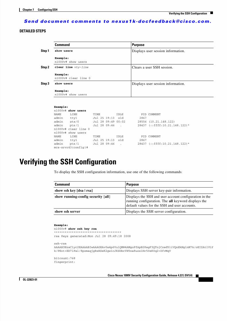
8/13/2019 n1000v Security
http://slidepdf.com/reader/full/n1000v-security 123/234
S e n d d o c u m e n t c o m m e n t s t o n e x u s 1 k - d o c f e e d b a c k @ c i s c o . c o m .
7-13Cisco Nexus 1000V Security Configuration Guide, Release 4.2(1) SV1(4)
OL-22823-01
Chapter 7 Configuring SSHVerifying the SSH Configuration
DETAILED STEPS
Example:n1000v# show usersNAME LINE TIME IDLE PID COMMENTadmin tty1 Jul 25 19:13 old 2867admin pts/0 Jul 28 09:49 00:02 28556 (10.21.148.122)admin pts /1 Jul 28 09:46 . 28437 (::ffff:10.21.148.122)*n1000v# clear line 0n1000v# show usersNAME LINE TIME IDLE PID COMMENTadmin tty1 Jul 25 19:13 old 2867admin pts /1 Jul 28 09:46 . 28437 (::ffff:10.21.148.122)*
mcs-srvr43(config)#
Verifying the SSH ConfigurationTo display the SSH configuration information, use one of the following commands:
Example:n1000v# show ssh key rsa**************************************rsa Keys generated:Mon Jul 28 09:49:18 2008
ssh-rsaAAAAB3NzaC1yc2EAAAABIwAAAGEAv0a4p6VulQMW4AMgoPfApB2KegF3QTojCzed51iVQnEkNglnM7A/oEIZAtlVLYk/PEzt+ED7lPal/8pomaqjgRxHSeK2gw1cJKSDbcYH5na8uox1Hr50eK0q2+ZfvMqV
bitcount:768fingerprint:
Command Purpose
Step 1 show users
Example:n1000v# show users
Displays user session information.
Step 2 clear line vty-line
Example:n1000v# clear line 0
Clears a user SSH session.
Step 3 show users
Example:n1000v# show users
Displays user session information.
Command Purpose
show ssh key [dsa | rsa] Displays SSH server key-pair information.
show running-config security [all ] Displays the SSH and user account configuration in therunning configuration. The all keyword displays thedefault values for the SSH and user accounts.
show ssh server Displays the SSH server configuration.

8/13/2019 n1000v Security
http://slidepdf.com/reader/full/n1000v-security 124/234
S e n d d o c u m e n t c o m m e n t s t o n e x u s 1 k - d o c f e e d b a c k @ c i s c o . c o m .
7-14Cisco Nexus 1000V Security Configuration Guide, Release 4.2(1) SV1(4)
OL-22823-01
Chapter 7 Configuring SSHSSH Example Configuration
76:6c:a0:5c:79:a6:ae:3d:cb:27:a1:86:62:fa:09:df**************************************
SSH Example ConfigurationTo configure SSH with an OpenSSH key, follow these steps:
Step 1 Disable the SSH server.
n1000v# config tn1000v(config)# no feature ssh
Step 2 Generate an SSH server key.
n1000v(config)# ssh key rsagenerating rsa key(1024 bits)......generated rsa key
Step 3 Enable the SSH server.
n1000v(config)# feature ssh
Step 4 Display the SSH server key.
n1000v(config)# show ssh keyrsa Keys generated:Sat Sep 29 00:10:39 2007
ssh-rsa AAAAB3NzaC1yc2EAAAABIwAAAIEAvWhEBsF55oaPHNDBnpXOTw6+/OdHoLJZKr+MZm99n2U0ChzZG4svRWmHuJY4PeDWl0e5yE3g3EO3pjDDmt923siNiv5aSga60K36lr39HmXL6VgpRVn1XQFiBwn4na+H1d3Q0hDt+uWEA0tka2uOtXlDhliEmn4HVXOjGhFhoNE=
bitcount:1024fingerprint:51:6d:de:1c:c3:29:50:88:df:cc:95:f0:15:5d:9a:df**************************************
could not retrieve dsa key information**************************************
Step 5 Specify the SSH public key in OpenSSH format.
n1000v(config)# username User1 sshkey ssh-rsa AAAAB3NzaC1yc2EAAAABIwAAAIEAy19oF6QaZl9G+3f1XswK3OiW4H7YyUyuA50rv7gsEPjhOBYmsi6PAVKui1nIf/
DQhum+lJNqJP/eLowb7ubO+lVKRXFY/G+lJNIQW3g9igG30c6k6+XVn+NjnI1B7ihvpVh7dLddMOXwOnXHYshXmSiH3UD/vKyziEh5S4Tplx8=
Step 6 Save the configuration.
n1000v(config)# copy running-config startup-config
Example :n1000v# config tn1000v(config)# no feature sshn1000v(config)# ssh key rsagenerating rsa key(1024 bits).....n1000v(config)# feature sshn1000v(config)# show ssh keyrsa Keys generated:Sat Sep 29 00:10:39 2007ssh-rsa AAAAB3NzaC1yc2EAAAABIwAAAIEAvWhEBsF55oaPHNDBnpXOTw6+/OdHoLJZKr+MZm99n2U0ChzZG4svRWmHuJY4PeDWl0e5yE3g3EO3pjDDmt923siNiv5aSga60K36lr39HmXL6VgpRVn1XQFiBwn4

8/13/2019 n1000v Security
http://slidepdf.com/reader/full/n1000v-security 125/234
S e n d d o c u m e n t c o m m e n t s t o n e x u s 1 k - d o c f e e d b a c k @ c i s c o . c o m .
7-15Cisco Nexus 1000V Security Configuration Guide, Release 4.2(1) SV1(4)
OL-22823-01
Chapter 7 Configuring SSHAdditional References
na+H1d3Q0hDt+uWEA0tka2uOtXlDhliEmn4HVXOjGhFhoNE=bitcount:1024fingerprint:51:6d:de:1c:c3:29:50:88:df:cc:95:f0:15:5d:9a:df**************************************could not retrieve dsa key information**************************************
n1000v(config)# username User1 sshkey ssh-rsa AAAAB3NzaC1yc2EAAAABIwAAAIEAy19oF6QaZl9G+3f1XswK3OiW4H7YyUyuA50rv7gsEPjhOBYmsi6PAVKui1nIf/
DQhum+lJNqJP/eLowb7ubO+lVKRXFY/G+lJNIQW3g9igG30c6k6+XVn+NjnI1B7ihvpVh7dLddMOXwOnXHYshXmSiH3UD/vKyziEh5S4Tplx8=n1000v(config)# copy running-config startup-config[########################################] 100%n1000v(config)#
Additional ReferencesFor additional information related to implementing RBAC, see the following sections: • Related Documents, page 7-15
• Standards, page 7-15
Related Documents
Standards
Feature History for SSHThis section provides the SSH release history.
Related Topic Document Title
CLI Cisco Nexus 1000V Getting Started Guide, Release 4.2(1)SV1(4)
Telnet Chapter 8, “Configuring Telnet”
Standards Title
No new or modified standards are supported by thisfeature, and support for existing standards has not beenmodified by this feature.
—
Feature Name Releases Feature Information
SSH 4.0(4)SV1(1) This feature was introduced.

8/13/2019 n1000v Security
http://slidepdf.com/reader/full/n1000v-security 126/234
S e n d d o c u m e n t c o m m e n t s t o n e x u s 1 k - d o c f e e d b a c k @ c i s c o . c o m .
7-16Cisco Nexus 1000V Security Configuration Guide, Release 4.2(1) SV1(4)
OL-22823-01
Chapter 7 Configuring SSHFeature History for SSH

8/13/2019 n1000v Security
http://slidepdf.com/reader/full/n1000v-security 127/234
C H A P T E R
S e n d d o c u m e n t c o m m e n t s t o n e x u s 1 k - d o c f e e d b a c k @ c i s c o . c o m .
8-1Cisco Nexus 1000V Security Configuration Guide, Release 4.2(1) SV1(4)
OL-22823-01
8Configuring Telnet
This chapter describes how to configure Telnet and includes the following topics:
• Information About the Telnet Server, page 8-1
• Prerequisites for Telnet, page 8-1
• Guidelines and Limitations, page 8-2
• Default Setting, page 8-2
• Configuring Telnet, page 8-2
• Verifying the Telnet Configuration, page 8-5
• Additional References, page 8-5
• Feature History for Telnet, page 8-6
Information About the Telnet ServerThe Telnet protocol enables you to set up TCP/IP connections to a host. Telnet allows a person at onesite to establish a TCP connection to a login server at another site and then passes the keystrokes fromone device to the other. Telnet can accept either an IP address or a domain name as the remote deviceaddress.
Prerequisites for TelnetTelnet has the following prerequisites:
• You have configured IP on a Layer 3 interface, out-of-band on the mgmt 0 interface, or inband onan Ethernet interface.
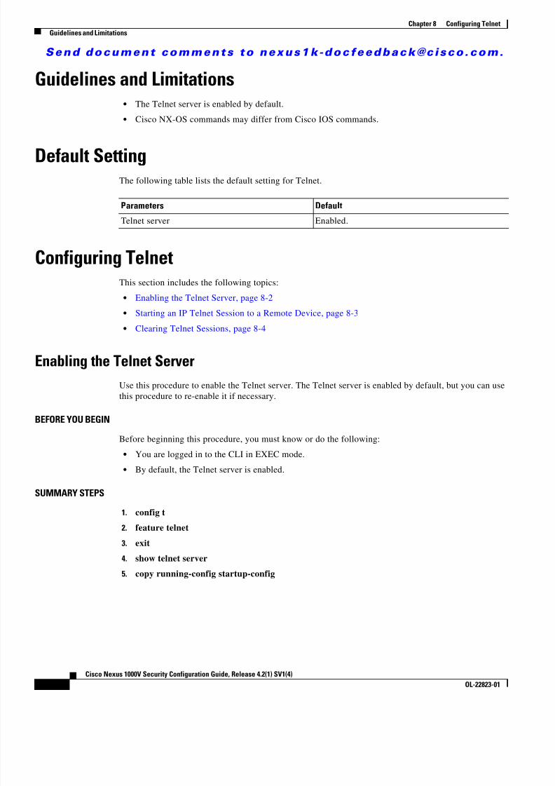
8/13/2019 n1000v Security
http://slidepdf.com/reader/full/n1000v-security 128/234
S e n d d o c u m e n t c o m m e n t s t o n e x u s 1 k - d o c f e e d b a c k @ c i s c o . c o m .
8-2Cisco Nexus 1000V Security Configuration Guide, Release 4.2(1) SV1(4)
OL-22823-01
Chapter 8 Configuring TelnetGuidelines and Limitations
Guidelines and Limitations • The Telnet server is enabled by default.
• Cisco NX-OS commands may differ from Cisco IOS commands.
Default SettingThe following table lists the default setting for Telnet.
Configuring TelnetThis section includes the following topics:
• Enabling the Telnet Server, page 8-2
• Starting an IP Telnet Session to a Remote Device, page 8-3
• Clearing Telnet Sessions, page 8-4
Enabling the Telnet ServerUse this procedure to enable the Telnet server. The Telnet server is enabled by default, but you can usethis procedure to re-enable it if necessary.
BEFORE YOU BEGIN
Before beginning this procedure, you must know or do the following:
• You are logged in to the CLI in EXEC mode.
• By default, the Telnet server is enabled.
SUMMARY STEPS
1. config t
2. feature telnet
3. exit
4. show telnet server
5. copy running-config startup-config
Parameters Default
Telnet server Enabled.

8/13/2019 n1000v Security
http://slidepdf.com/reader/full/n1000v-security 129/234

8/13/2019 n1000v Security
http://slidepdf.com/reader/full/n1000v-security 130/234
S e n d d o c u m e n t c o m m e n t s t o n e x u s 1 k - d o c f e e d b a c k @ c i s c o . c o m .
8-4Cisco Nexus 1000V Security Configuration Guide, Release 4.2(1) SV1(4)
OL-22823-01
Chapter 8 Configuring TelnetConfiguring Telnet
DETAILED STEPS
Clearing Telnet SessionsUse this procedure to clear Telnet sessions.
BEFORE YOU BEGIN
Before beginning this procedure, you must know or do the following.
• You are logged in to the CLI in EXEC mode.
SUMMARY STEPS
1. show users
2. clear line vty-line
DETAILED STEPS
Example:
n1000v# show usersNAME LINE TIME IDLE PID COMMENTadmin tty1 Jul 25 19:13 old 2867admin pts /1 Jul 28 14:04 . 31453 (::ffff:171.70.209.8)admin pts /2 Jul 28 14:04 . 31475 (171.70.209.8)*n1000v# clear line 1n1000v# show usersNAME LINE TIME IDLE PID COMMENTadmin tty1 Jul 25 19:13 old 2867admin pts /2 Jul 28 14:04 . 31475 (171.70.209.8)*n1000v#
Command Purpose
Step 1 telnet { ip address | host-name } [ port-number ] [ vrf vrf-name ]
Example:n1000v# telnet 10.10.1.1
Creates an IP Telnet session to the specified destination.
port-number : The port number, from 1 to 65535, to usefor this session. The default port number is 23.
vrf-name : The default VRF is the default VRF.
Command Purpose
Step 1 show users
Example:n1000v# show users
Displays user session information.
Step 2 clear line vty-line
Example:n1000v# clear line 1
Clears a user Telnet session.
Step 3 show users
Example:n1000v# show users
Displays user session information.

8/13/2019 n1000v Security
http://slidepdf.com/reader/full/n1000v-security 131/234
S e n d d o c u m e n t c o m m e n t s t o n e x u s 1 k - d o c f e e d b a c k @ c i s c o . c o m .
8-5Cisco Nexus 1000V Security Configuration Guide, Release 4.2(1) SV1(4)
OL-22823-01
Chapter 8 Configuring TelnetVerifying the Telnet Configuration
Verifying the Telnet ConfigurationTo display the Telnet configuration information, use one of the following commands:
Example:n1000v# show running-config security allversion 4.0(1)
username admin password 5 $1$xMw2Q/1S$ZEWRvyAxAJAFV0weuSPvg1 role network-adminusername user2 password 5 $1$byNNnnSP$xfXVKjE5UEScvriwX3Kyj0 role network-operatorusername user2 sshkey ssh-rsaAAAAB3NzaC1yc2EAAAABIwAAAQEAyKcb7Nv9Ki1OOId9/tdHHa/ngQujlvK5mXyL/n+DeOXKfVhHbX2a+V0cm7CCLUkBh+BvZRmpmOVTmU/5awfVhVxMKXMiPOPBc+A6/n3FVroyRwupMki6mWoM6UwaGID5gsVPqFjFNSgMWtbhjo97XVKhgjFW+wOVt8QoAcrEtnwEfsnQk1EIr/0XIP1mqTsrqTsmjZ2vLk+fFzTGYAxMvYZI+BrN47aoH2ywS7CpnODjCDXJuDYSPbc3PA8t0ghU/60m9R+s6AZPuljVQbGfxPrahEu4GVc6sMJNU1JxmqDJkodhMArObB4Umzj7E3Rdby/ZWx/clTYiXQR1X1VfhQ==telnet server enable
banner motd # User Access Verification #
ssh key rsa 1024 forceno ssh key dsa forcessh server enable
Additional ReferencesFor additional information related to implementing Telnet, see the following sections:
• Related Documents, page 8-5
• Standards, page 8-6
Related Documents
Command Purposeshow running-config security [all ] Displays the user account configuration in the running
configuration. The all keyword displays the defaultvalues for the user accounts.
show telnet server Displays the telnet server configuration.
show hosts Displays the configuration details for current hosts.
show tcp connection Displays connection information.
Related Topic Document Title
SSH Chapter 7, “Configuring SSH”
CLI Cisco Nexus 1000V Getting Started Guide, Release 4.2(1)SV1(4)

8/13/2019 n1000v Security
http://slidepdf.com/reader/full/n1000v-security 132/234
S e n d d o c u m e n t c o m m e n t s t o n e x u s 1 k - d o c f e e d b a c k @ c i s c o . c o m .
8-6Cisco Nexus 1000V Security Configuration Guide, Release 4.2(1) SV1(4)
OL-22823-01
Chapter 8 Configuring TelnetFeature History for Telnet
Standards
Feature History for TelnetThis section provides the Telnet release history.
Standards Title
No new or modified standards are supported by thisfeature, and support for existing standards has not beenmodified by this feature.
—
Feature Name Releases Feature Information
Telnet 4.0(4)SV1(1) This feature was introduced.

8/13/2019 n1000v Security
http://slidepdf.com/reader/full/n1000v-security 133/234
C H A P T E R
S e n d d o c u m e n t c o m m e n t s t o n e x u s 1 k - d o c f e e d b a c k @ c i s c o . c o m .
9-1Cisco Nexus 1000V Security Configuration Guide, Release 4.2(1) SV1(4)
OL-22823-01
9Configuring an IP ACL
This chapter describes how to configure IP access control lists (ACLs).
This chapter includes the following sections:
• Information About ACLs, page 9-1
• Prerequisites for IP ACLs, page 9-5
• Guidelines and Limitations, page 9-5
• Default Settings, page 9-5
• Configuring IP ACLs, page 9-5
• Verifying IP ACL Configurations, page 9-14
• Monitoring IP ACL, page 9-15
• Example Configurations for IP ACL, page 9-15
• Additional References, page 9-15
• Feature History for IP ACL, page 9-16
Information About ACLsAn ACL is an ordered set of rules for filtering traffic. When the device determines that an ACL appliesto a packet, it tests the packet against the rules . The first matching rule determines whether the packet ispermitted or denied. If there is no match, the device applies a default rule. The device processes packetsthat are permitted and drops packets that are denied. For more information, see the “Implicit Rules”section on page 9-3 .
You can use ACLs to protect networks and specific hosts from unnecessary or unwanted traffic. Forexample, you could use ACLs to disallow HTTP traffic from a high-security network to the Internet. Youcould also use ACLs to allow HTTP traffic but only to specific sites, using the IP address of the site toidentify it in an IP ACL.
This section includes the following topics:
• ACL Types and Applications, page 9-2
• Order of ACL Application, page 9-2
• About Rules, page 9-2
• Statistics, page 9-4

8/13/2019 n1000v Security
http://slidepdf.com/reader/full/n1000v-security 134/234
S e n d d o c u m e n t c o m m e n t s t o n e x u s 1 k - d o c f e e d b a c k @ c i s c o . c o m .
9-2Cisco Nexus 1000V Security Configuration Guide, Release 4.2(1) SV1(4)
OL-22823-01
Chapter 9 Configuring an IP ACLInformation About ACLs
ACL Types and ApplicationsWhen a port ACL is applied to a trunk port, the ACL filters traffic on all VLANs on the trunk port.
The following types of port ACLs are supported for filtering Layer 2 traffic:
• IP ACLs—The device applies IPv4 ACLs only to IP traffic.
• MAC ACLs—The device applies MAC ACLs only to non-IP traffic.
Order of ACL ApplicationACLs are applied in the following order:
1. Incoming Port ACL
2. Outgoing Port ACL
About RulesRules are what you create, modify, and remove when you configure how an ACL filters network traffic.Rules appear in the running configuration. When you apply an ACL to an interface or change a rulewithin an ACL that is already applied to an interface, the supervisor module creates ACL entries fromthe rules in the running configuration and sends those ACL entries to the applicable I/O module.
You can create rules in ACLs in access-list configuration mode by using the permit or deny command.The device allows traffic that matches the criteria in a permit rule and blocks traffic that matches thecriteria in a deny rule. You have many options for configuring the criteria that traffic must meet in orderto match the rule.
This section describes some of the options that you can use when you configure a rule. For informationabout every option, see the applicable permit and deny commands in the Cisco Nexus 1000V Command
Reference, Release 4 .2(1)SV1(4) .This section includes the following topics:
• Source and Destination, page 9-2
• Protocols, page 9-3
• Implicit Rules, page 9-3
• Additional Filtering Options, page 9-3
• Sequence Numbers, page 9-4
• Statistics, page 9-4
• Statistics, page 9-4
Source and Destination
In each rule, you specify the source and the destination of the traffic that matches the rule. You canspecify both the source and destination as a specific host, a network or group of hosts, or any host. Howyou specify the source and destination depends on whether you are configuring IP or MAC ACLs. Forinformation about specifying source and destination, see the applicable permit and deny commands inthe Cisco Nexus 1000V Command Reference, Release 4.2(1)SV1(4) .

8/13/2019 n1000v Security
http://slidepdf.com/reader/full/n1000v-security 135/234
S e n d d o c u m e n t c o m m e n t s t o n e x u s 1 k - d o c f e e d b a c k @ c i s c o . c o m .
9-3Cisco Nexus 1000V Security Configuration Guide, Release 4.2(1) SV1(4)
OL-22823-01
Chapter 9 Configuring an IP ACLInformation About ACLs
Protocols
IP and MAC ACLs let you to identify traffic by protocol. You can specify some protocols by name. Forexample, in an IP ACL, you can specify ICMP by name.
You can specify any protocol by number. In MAC ACLs, you can specify protocols by the Ethertype
number of the protocol, which is a hexadecimal number. For example, you can use 0x0800 to specify IPtraffic in a MAC ACL rule.
In IP ACLs, you can specify protocols by the integer that represents the Internet protocol number. Forexample, you can use 115 to specify Layer 2 Tunneling Protocol (L2TP) traffic.
For a list of the protocols that each type of ACL supports by name, see the applicable permit and denycommands in the Cisco Nexus 1000V Command Reference, Release 4.2(1)SV1(4) .
Implicit Rules
IP and MAC ACLs have implicit rules, which means that although these rules do not appear in therunning configuration, the device applies them to traffic when no other rules in an ACL match. Whenyou configure the device to maintain per-rule statistics for an ACL, the device does not maintainstatistics for implicit rules.
All IP ACLs include the following implicit rule that denies unmatched IP traffic:
deny ip any any
All MAC ACLs include the following implicit rule:
deny any any
This implicit rule ensures that unmatched traffic is denied, regardless of the protocol specified in theLayer 2 header of the traffic.
Additional Filtering Options
You can identify traffic by using additional options. These options differ by ACL type. The followinglist includes most but not all additional filtering options:
• IP ACLs support the following additional filtering options: – Layer 4 protocol – TCP and UDP ports – ICMP types and codes – IGMP types – Precedence level – Differentiated Services Code Point (DSCP) value
– TCP packets with the ACK, FIN, PSH, RST, SYN, or URG bit set
• MAC ACLs support the following additional filtering options: – Layer 3 protocol – VLAN ID – Class of Service (CoS)
For information about all filtering options available in rules, see the applicable permit and deny commands in the Cisco Nexus 1000V Command Reference, Release 4.2(1)SV1(4) .

8/13/2019 n1000v Security
http://slidepdf.com/reader/full/n1000v-security 136/234

8/13/2019 n1000v Security
http://slidepdf.com/reader/full/n1000v-security 137/234

8/13/2019 n1000v Security
http://slidepdf.com/reader/full/n1000v-security 138/234
S e n d d o c u m e n t c o m m e n t s t o n e x u s 1 k - d o c f e e d b a c k @ c i s c o . c o m .
9-6Cisco Nexus 1000V Security Configuration Guide, Release 4.2(1) SV1(4)
OL-22823-01
Chapter 9 Configuring an IP ACLConfiguring IP ACLs
Creating an IP ACLYou can create an IPv4 ACL on the device and add rules to it.
BEFORE YOU BEGIN
Before beginning this procedure, you must know or do the following:
• You are logged in to the CLI in EXEC mode.
SUMMARY STEPS
1. config t
2. [no] ip access-list {name | match-local-traffic } 3. [sequence-number ] {permit | deny } protocol source destination
4. statistics per-entry
5. show ip access-lists name
6. copy running-config startup-config
DETAILED STEPS
Command Purpose
Step 1 config t
Example:n1000v# config tn1000v(config)#
Places you into CLI Global Configuration mode.
Step 2 [no] ip access-list { name |
match-local-traffic }Example:n1000v(config)# ip access-list acl-01n1000v(config-acl)#
Example:n1000v(config)# ip access-list
match-local-trafficn1000v(config-acl)#
Creates the named IP ACL (up to 64 characters in
length) and enters IP ACL configuration mode.The match-local-traffic option enables matchingfor locally-generated traffic.
The no option removes the specified access list.

8/13/2019 n1000v Security
http://slidepdf.com/reader/full/n1000v-security 139/234
S e n d d o c u m e n t c o m m e n t s t o n e x u s 1 k - d o c f e e d b a c k @ c i s c o . c o m .
9-7Cisco Nexus 1000V Security Configuration Guide, Release 4.2(1) SV1(4)
OL-22823-01
Chapter 9 Configuring an IP ACLConfiguring IP ACLs
Changing an IP ACLYou can add and remove rules in an existing IPv4 ACL. You cannot change existing rules. Instead, tochange a rule, you can remove it and recreate it with the desired changes.
If you need to add more rules between existing rules than the current sequence numbering allows, youcan use the resequence command to reassign sequence numbers. For more information, see the“Changing Sequence Numbers in an IP ACL” section on page 9-10 .
BEFORE YOU BEGIN
Before beginning this procedure, you must know or do the following:
• You are logged in to the CLI in EXEC mode.
SUMMARY STEPS
1. config t
2. ip access-list name
3. [sequence-number ] {permit | deny } protocol source destination
4. no {sequence-number | { permit | deny } protocol source destination }
5. [no ] statistics per-entry
6. show ip access-list name
7. copy running-config startup-config
Step 3 [ sequence-number ] { permit | deny } protocol source destination
Example:n1000v(config-acl)# permit ip192.168.2.0/24 any
Creates a rule in the IP ACL. You can create manyrules. The sequence-number argument can be awhole number between 1 and 4294967295.
The permit and deny commands support manyways of identifying traffic. For more information,see the Cisco Nexus 1000V Command Reference,
Release 4.2(1)SV1(4) .
Step 4 statistics per-entry
Example:n1000v(config-acl)# statistics per-entry
(Optional) Specifies that the device maintainsglobal statistics for packets that match the rules inthe ACL.
Step 5 show ip access-lists name
Example:n1000v(config-acl)# show ip access-listsacl-01
(Optional) Displays the IP ACL configuration.
Step 6 copy running-config startup-config
Example:n1000v(config-acl)# copy running-configstartup-config
(Optional) Copies the running configuration to thestartup configuration.
Command Purpose

8/13/2019 n1000v Security
http://slidepdf.com/reader/full/n1000v-security 140/234
S e n d d o c u m e n t c o m m e n t s t o n e x u s 1 k - d o c f e e d b a c k @ c i s c o . c o m .
9-8Cisco Nexus 1000V Security Configuration Guide, Release 4.2(1) SV1(4)
OL-22823-01
Chapter 9 Configuring an IP ACLConfiguring IP ACLs
DETAILED STEPS
Command Purpose
Step 1 config t
Example:n1000v# config tn1000v(config)#
Places you into CLI Global Configuration mode.
Step 2 ip access-list name
Example:n1000v(config)# ip access-list acl-01n1000v(config-acl)#
Places you into IP ACL configuration mode for thespecified ACL.
Step 3 [ sequence-number ] { permit | deny } protocol source destination
Example:n1000v(config-acl)# 100 permit ip192.168.2.0/24 any
(Optional) Creates a rule in the IP ACL. Using asequence number allows you to specify a positionfor the rule in the ACL. Without a sequence number,the rule is added to the end of the rules. Thesequence-number argument can be a whole numberbetween 1 and 4294967295.The permit and deny commands support manyways of identifying traffic. For more information,see the Cisco Nexus 1000V Command Reference,
Release 4 .2(1)SV1(4)
Step 4 no { sequence-number | { permit | deny } protocol source destination }
Example:n1000v(config-acl)# no 80
(Optional) Removes the rule that you specifiedfrom the IP ACL.
The permit and deny commands support manyways of identifying traffic. For more information,see the Cisco Nexus 1000V Command Reference,
Release 4 .2(1)SV1(4) .
Step 5 [ no ] statistics per-entry
Example:n1000v(config-acl)# statistics per-entry
(Optional) Specifies that the device maintainsglobal statistics for packets that match the rules inthe ACL.
The no option stops the device from maintainingglobal statistics for the ACL.
Step 6 show ip access-lists name
Example:n1000v(config-acl)# show ip access-listsacl-01
(Optional) Displays the IP ACL configuration.
Step 7 copy running-config startup-config
Example:
n1000v(config-acl)# copy running-configstartup-config
(Optional) Copies the running configuration to thestartup configuration.
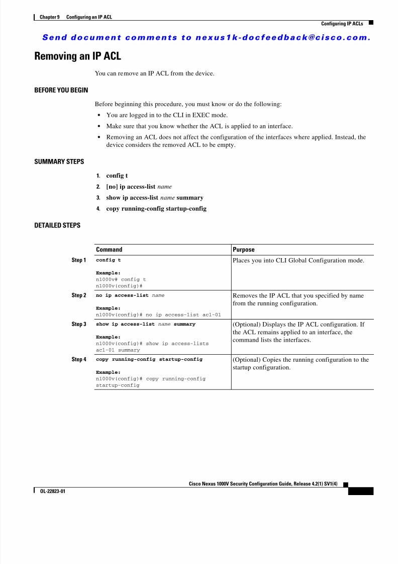
8/13/2019 n1000v Security
http://slidepdf.com/reader/full/n1000v-security 141/234
S e n d d o c u m e n t c o m m e n t s t o n e x u s 1 k - d o c f e e d b a c k @ c i s c o . c o m .
9-9Cisco Nexus 1000V Security Configuration Guide, Release 4.2(1) SV1(4)
OL-22823-01
Chapter 9 Configuring an IP ACLConfiguring IP ACLs
Removing an IP ACLYou can remove an IP ACL from the device.
BEFORE YOU BEGIN
Before beginning this procedure, you must know or do the following:
• You are logged in to the CLI in EXEC mode.
• Make sure that you know whether the ACL is applied to an interface.
• Removing an ACL does not affect the configuration of the interfaces where applied. Instead, thedevice considers the removed ACL to be empty.
SUMMARY STEPS
1. config t
2. [no] ip access-list name
3. show ip access-list name summary4. copy running-config startup-config
DETAILED STEPS
Command Purpose
Step 1 config t
Example:n1000v# config tn1000v(config)#
Places you into CLI Global Configuration mode.
Step 2 no ip access-list name
Example:n1000v(config)# no ip access-list acl-01
Removes the IP ACL that you specified by namefrom the running configuration.
Step 3 show ip access-list name summary
Example:n1000v(config)# show ip access-listsacl-01 summary
(Optional) Displays the IP ACL configuration. Ifthe ACL remains applied to an interface, thecommand lists the interfaces.
Step 4 copy running-config startup-config
Example:n1000v(config)# copy running-configstartup-config
(Optional) Copies the running configuration to thestartup configuration.

8/13/2019 n1000v Security
http://slidepdf.com/reader/full/n1000v-security 142/234

8/13/2019 n1000v Security
http://slidepdf.com/reader/full/n1000v-security 143/234
S e n d d o c u m e n t c o m m e n t s t o n e x u s 1 k - d o c f e e d b a c k @ c i s c o . c o m .
9-11Cisco Nexus 1000V Security Configuration Guide, Release 4.2(1) SV1(4)
OL-22823-01
Chapter 9 Configuring an IP ACLConfiguring IP ACLs
Applying an IP ACL as a Port ACLUse this procedure to configure a port ACL by applying an IPv4 or ACL to a Layer 2 interface physicalport.
BEFORE YOU BEGINBefore beginning this procedure, you must know or do the following:
• You are logged in to the CLI in EXEC mode.
• You can apply one port ACL to an interface.
• Make sure that the ACL you want to apply exists and that it is configured to filter traffic in themanner that you need for this application. For more information, see the “Creating an IP ACL”section on page 9-6 or the “Changing an IP ACL” section on page 9-7 .
• An IP ACL can also be configured in a port profile. For more information, see the “Adding an IPACL to a Port Profile” procedure on page 9-12 .
SUMMARY STEPS1. config t
2. interface vethernet port
3. ip port access-group access-list [in | out]
4. show running-config aclmgr
5. copy running-config startup-config
DETAILED STEPS
Command PurposeStep 1 config t
Example:n1000v# config tn1000v(config)#
Places you into CLI Global Configuration mode.
Step 2 interface vethernet port
Example:n1000v(config)# interface vethernet 40n1000v(config-if)#
Places you into Interface Configuration mode forthe specified vEthernet interface.
Step 3 ip port access-group access-list [ in | out ]
Example:n1000v(config-if)# ip port access-groupacl-l2-marketing-group in
Applies an inbound or outbound IPv4 ACL to theinterface. You can apply one port ACL to aninterface.
Step 4 show running-config aclmgr
Example:n1000v(config-if)# show running-configaclmgr
(Optional) Displays the ACL configuration.
8/13/2019 n1000v Security
http://slidepdf.com/reader/full/n1000v-security 144/234
S e n d d o c u m e n t c o m m e n t s t o n e x u s 1 k - d o c f e e d b a c k @ c i s c o . c o m .
9-12Cisco Nexus 1000V Security Configuration Guide, Release 4.2(1) SV1(4)
OL-22823-01
Chapter 9 Configuring an IP ACLConfiguring IP ACLs
Adding an IP ACL to a Port ProfileYou can use this procedure to add an IP ACL to a port profile:
BEFORE YOU BEGIN
Before beginning this procedure, you must know or do the following:
• You are logged in to the CLI in EXEC mode.
• You have already created the IP ACL to add to this port profile using the “Creating an IP ACL”procedure on page 9-6 ; and you know its name.
• If using an existing port profile, you have already created it and you know its name.
• If creating a new port profile, you know the interface type (Ethernet or vEthernet) and the name youwant to give the profile.
• For more information about port profiles, see the Cisco Nexus 1000V Port Profile ConfigurationGuide, Release 4.2(1)SV1(4) ;
• You know the name of the IP access control list that you want to configure for this port profile.
• You know the direction of packet flow for the access list.
SUMMARY STEPS1. config t
2. port-profile [type {ethernet | vethernet }] profile-name
3. ip port access-group name {in | out }
4. show port-profile [brief | expand-interface | usage ] [name profile-name ]
5. copy running-config startup-config
Step 5 copy running-config startup-config
Example:n1000v(config-if)# copy running-configstartup-config
(Optional) Copies the running configuration to thestartup configuration.
Command Purpose

8/13/2019 n1000v Security
http://slidepdf.com/reader/full/n1000v-security 145/234
S e n d d o c u m e n t c o m m e n t s t o n e x u s 1 k - d o c f e e d b a c k @ c i s c o . c o m .
9-13Cisco Nexus 1000V Security Configuration Guide, Release 4.2(1) SV1(4)
OL-22823-01
Chapter 9 Configuring an IP ACLConfiguring IP ACLs
DETAILED STEPS
Applying an IP ACL to the Management InterfaceUse this procedure to applying an IPv4 or ACL to the Management interface, mgmt0.
BEFORE YOU BEGIN
Before beginning this procedure, you must know or do the following:
• You are logged in to the CLI in EXEC mode.
• Make sure that the ACL you want to apply exists and that it is configured to filter traffic in themanner that you need for this application. For more information, see the “Creating an IP ACL”section on page 9-6 or the “Changing an IP ACL” section on page 9-7 .
SUMMARY STEPS
1. config t
2. interface mgmt0
3. [no] ip access-group access-list [in | out]
4. show ip access-lists access-list
5. copy running-config startup-config
Command Description
Step 1 config t
Example:n1000v# config tn1000v(config)#
Enters global configuration mode.
Step 2 port-profile [ type {ethernet | vethernet }]name
Example:n1000v(config)# port-profile AccessProfn1000v(config-port-prof)#
Enters port profile configuration mode for thenamed port profile.
Step 3 ip port access-group name { in | out }
Example:n1000v(config-port-prof)# ip portaccess-group allaccess4 out
Adds the named ACL to the port profile for eitherinbound or outbound traffic.
Step 4 show port-profile name profile-name
Example:n1000v(config-port-prof)# show port-profilename AccessProf
(Optional) Displays the configuration forverification.
Step 5 copy running-config startup-config
Example:n1000v(config-port-prof)# copyrunning-config startup-config
(Optional) Saves the running configurationpersistently through reboots and restarts bycopying it to the startup configuration.

8/13/2019 n1000v Security
http://slidepdf.com/reader/full/n1000v-security 146/234
8/13/2019 n1000v Security
http://slidepdf.com/reader/full/n1000v-security 147/234
S e n d d o c u m e n t c o m m e n t s t o n e x u s 1 k - d o c f e e d b a c k @ c i s c o . c o m .
9-15Cisco Nexus 1000V Security Configuration Guide, Release 4.2(1) SV1(4)
OL-22823-01
Chapter 9 Configuring an IP ACLMonitoring IP ACL
Monitoring IP ACLUse the following commands for IP ACL monitoring:
Example Configurations for IP ACLThe following example shows how to create an IPv4 ACL named acl-01 and apply it as a port ACL tovEthernet interface 40:
ip access-list acl-01permit ip 192.168.2.0/24 any
interface vethernet 40ip port access-group acl-01 in
The following example shows how to enable access list matching for locally-generated traffic:
ip access-list match-local-traffic
Additional ReferencesFor additional information related to implementing IP ACLs, see the following sections:
• Related Documents, page 9-16
• Standards, page 9-16
show ip access-list [name ] summary Displays a summary of all configured IPv4 ACLsor a named IPv4 ACL.
show running-config interface Displays the configuration of an interface towhich you have applied an ACL.
Command Purpose
Command Purpose
show ip access-lists Displays IPv4 ACL configuration. If the IPv4ACL includes the statistics per-entry command,then the show ip access-lists command output
includes the number of packets that have matchedeach rule.
clear ip access-list counters Clears statistics for all IPv4 ACLs or for a specificIPv4 ACL.

8/13/2019 n1000v Security
http://slidepdf.com/reader/full/n1000v-security 148/234
8/13/2019 n1000v Security
http://slidepdf.com/reader/full/n1000v-security 149/234
C H A P T E R
S e n d d o c u m e n t c o m m e n t s t o n e x u s 1 k - d o c f e e d b a c k @ c i s c o . c o m .
10-1Cisco Nexus 1000V Security Configuration Guide, Release 4.2(1) SV1(4)
OL-22823-01
10Configuring a MAC ACL
This chapter describes how to configure MAC access control lists (ACLs), and includes the followingsections:
• Information About MAC ACLs, page 10-1
• Prerequisites for MAC ACLs, page 10-1 \
• Default Settings, page 10-2
• Configuring MAC ACLs, page 10-2
• Verifying MAC ACL Configurations, page 10-9
• Monitoring MAC ACLs, page 10-10
• Example Configurations for MAC ACLs, page 10-11
• Additional References, page 10-11
• Feature History for MAC ACL, page 10-12
Information About MAC ACLsMAC ACLs are ACLs that filter traffic using information in the Layer 2 header of each packet.
Prerequisites for MAC ACLsMAC ACLs have the following prerequisites:
• You are familiar with MAC addressing and non-IP protocols to configure MAC ACLs.
• You are familiar with the concepts in the “Information About ACLs” section on page 9-1 .
Guidelines and LimitationsMAC ACLs have the following configuration guidelines and limitations:
• In most cases, ACL processing for IP packets are processed on the I/O modules. Managementinterface traffic is always processed on the supervisor module, which is slower.
• ACLs are not supported in port channels.
8/13/2019 n1000v Security
http://slidepdf.com/reader/full/n1000v-security 150/234
S e n d d o c u m e n t c o m m e n t s t o n e x u s 1 k - d o c f e e d b a c k @ c i s c o . c o m .
10-2Cisco Nexus 1000V Security Configuration Guide, Release 4.2(1) SV1(4)
OL-22823-01
Chapter 10 Configuring a MAC ACLDefault Settings
Default SettingsTable 10-1 lists MAC ACL defaults.
Configuring MAC ACLsThis section includes the following topics:
• Creating a MAC ACL, page 10-2
• Changing a MAC ACL, page 10-3
• Removing a MAC ACL, page 10-5
• Changing Sequence Numbers in a MAC ACL, page 10-6
• Applying a MAC ACL as a Port ACL, page 10-7
• Adding a MAC ACL to a Port Profile, page 10-8
Creating a MAC ACLUse this procedure to create a MAC ACL and add rules to it. You can also use this procedure to add theACL to a port profile.
BEFORE YOU BEGIN
Before beginning this procedure, you must know or do the following:
• You are logged in to the CLI in EXEC mode.
• You have a name to assign to the ACL you are creating.
• If you want to also add the ACL to a port-profile, you must know or do the following: – If using an existing port profile, you have already created it using the Cisco Nexus 1000V Port
Profile Configuration Guide, Release 4.2(1)SV1(4) ; and you know its name. – If creating a new port profile, you know the interface type (Ethernet or vEthernet) and the name
you want to give the profile. – You know the direction of packet flow for the access list.
SUMMARY STEPS
1. config t
2. mac access-list name
3. {permit | deny } source destination protocol
Table 10-1 Default MAC ACLs Parameters
Parameters Default
MAC ACLs No MAC ACLs exist by default
ACL rules Implicit rules apply to all ACLs (see the “ImplicitRules” section on page 9-3 )

8/13/2019 n1000v Security
http://slidepdf.com/reader/full/n1000v-security 151/234
S e n d d o c u m e n t c o m m e n t s t o n e x u s 1 k - d o c f e e d b a c k @ c i s c o . c o m .
10-3Cisco Nexus 1000V Security Configuration Guide, Release 4.2(1) SV1(4)
OL-22823-01
Chapter 10 Configuring a MAC ACLConfiguring MAC ACLs
4. statistics per-entry
5. show mac access-lists name
6. copy running-config startup-config
DETAILED STEPS
Changing a MAC ACLUse this procedure to change an existing MAC ACL, for example, to add or remove rules.
BEFORE YOU BEGIN
Before beginning this procedure, you must know or do the following:
• You are logged in to the CLI in EXEC mode.
• In an existing MAC ACL, you cannot change existing rules.
• In an existing MAC ACL, you can add and remove rules.
Command Purpose
Step 1 config t
Example:n1000v# config tn1000v(config)#
Places you into CLI Global Configuration mode.
Step 2 mac access-list name
Example:n1000v(config)# mac access-list acl-mac-01n1000v(config-mac-acl)#
Creates the MAC ACL and enters ACLconfiguration mode.
Step 3 { permit | deny } source destination protocol
Example:n1000v(config-mac-acl)# permit00c0.4f00.0000 0000.00ff.ffff any
Creates a rule in the MAC ACL.The permit and deny commands support manyways of identifying traffic. For more information,see the Cisco Nexus 1000V Command Reference,
Release 4.2(1)SV1(4) .
Step 4 statistics per-entry
Example:n1000v(config-mac-acl)# statisticsper-entry
(Optional) Specifies that the device maintainsglobal statistics for packets that match the rules inthe ACL.
Step 5 show mac access-lists name
Example:n1000v(config-mac-acl)# show macaccess-lists acl-mac-01
(Optional) Displays the MAC ACL configurationfor verification.
Step 6 copy running-config startup-config
Example:n1000v(config-mac-acl)# copyrunning-config startup-config
(Optional) Copies the running configuration to thestartup configuration.
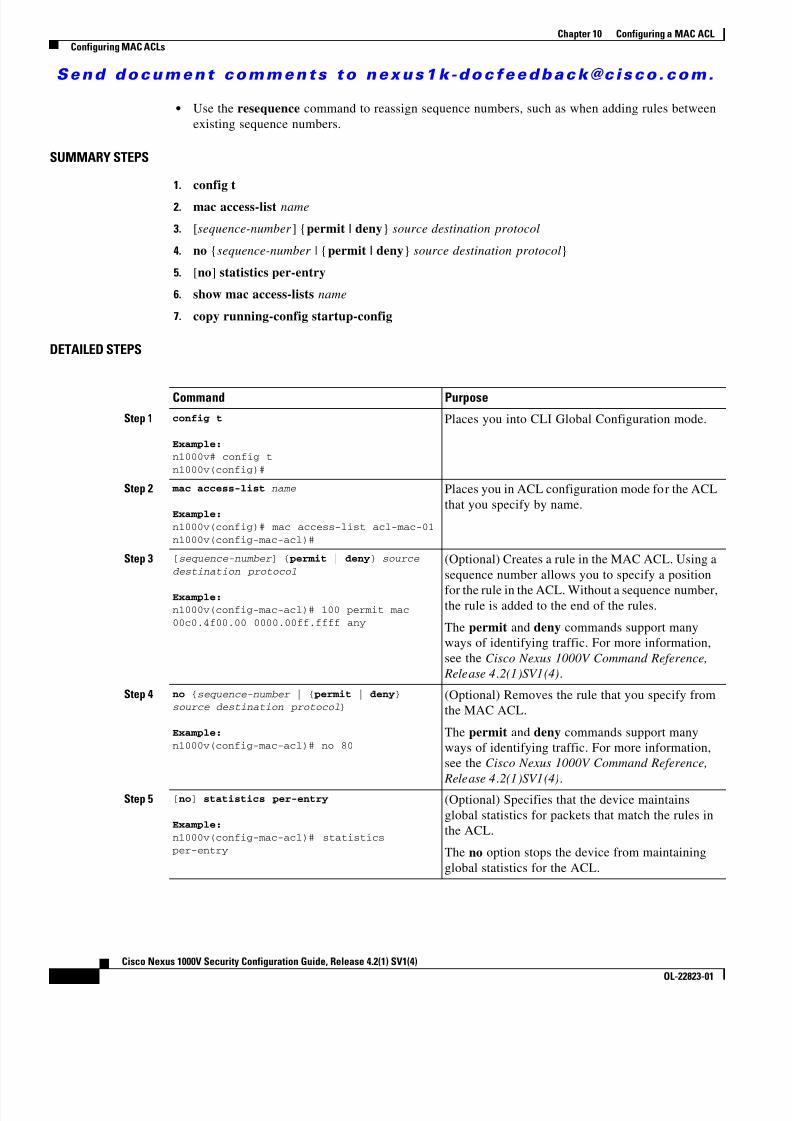
8/13/2019 n1000v Security
http://slidepdf.com/reader/full/n1000v-security 152/234
S e n d d o c u m e n t c o m m e n t s t o n e x u s 1 k - d o c f e e d b a c k @ c i s c o . c o m .
10-4Cisco Nexus 1000V Security Configuration Guide, Release 4.2(1) SV1(4)
OL-22823-01
Chapter 10 Configuring a MAC ACLConfiguring MAC ACLs
• Use the resequence command to reassign sequence numbers, such as when adding rules betweenexisting sequence numbers.
SUMMARY STEPS
1. config t
2. mac access-list name
3. [sequence-number ] {permit | deny } source destination protocol
4. no {sequence-number | { permit | deny } source destination protocol }
5. [no ] statistics per-entry
6. show mac access-lists name
7. copy running-config startup-config
DETAILED STEPS
Command PurposeStep 1 config t
Example:n1000v# config tn1000v(config)#
Places you into CLI Global Configuration mode.
Step 2 mac access-list name
Example:n1000v(config)# mac access-list acl-mac-01n1000v(config-mac-acl)#
Places you in ACL configuration mode for the ACLthat you specify by name.
Step 3 [ sequence-number ] { permit | deny } source destination protocol
Example:n1000v(config-mac-acl)# 100 permit mac00c0.4f00.00 0000.00ff.ffff any
(Optional) Creates a rule in the MAC ACL. Using asequence number allows you to specify a position
for the rule in the ACL. Without a sequence number,the rule is added to the end of the rules.
The permit and deny commands support manyways of identifying traffic. For more information,see the Cisco Nexus 1000V Command Reference,
Release 4 .2(1)SV1(4) .
Step 4 no { sequence-number | { permit | deny } source destination protocol }
Example:n1000v(config-mac-acl)# no 80
(Optional) Removes the rule that you specify fromthe MAC ACL.
The permit and deny commands support manyways of identifying traffic. For more information,see the Cisco Nexus 1000V Command Reference,
Release 4 .2(1)SV1(4) .
Step 5 [ no ] statistics per-entry
Example:n1000v(config-mac-acl)# statisticsper-entry
(Optional) Specifies that the device maintainsglobal statistics for packets that match the rules inthe ACL.
The no option stops the device from maintainingglobal statistics for the ACL.

8/13/2019 n1000v Security
http://slidepdf.com/reader/full/n1000v-security 153/234
S e n d d o c u m e n t c o m m e n t s t o n e x u s 1 k - d o c f e e d b a c k @ c i s c o . c o m .
10-5Cisco Nexus 1000V Security Configuration Guide, Release 4.2(1) SV1(4)
OL-22823-01
Chapter 10 Configuring a MAC ACLConfiguring MAC ACLs
Removing a MAC ACLUse this procedure to remove a MAC ACL.
BEFORE YOU BEGIN
Before beginning this procedure, you must know or do the following:
• You are logged in to the CLI in EXEC mode.
• Make sure that you know whether the ACL is applied to an interface.
• You can remove ACLs that are currently applied. Removing an ACL does not affect theconfiguration of interfaces where you have applied the ACL. Instead, removed ACLs are consideredempty.
• To find the interfaces that a MAC ACL is configured on, use the show mac access-lists commandwith the summary keyword.
SUMMARY STEPS
1. config t
2. no mac access-list name
3. show mac access-lists name summary
4. copy running-config startup-config
DETAILED STEPS
Step 6 show mac access-lists name
Example:n1000v(config-mac-acl)# show macaccess-lists acl-mac-01
(Optional) Displays the MAC ACL configuration.
Step 7 copy running-config startup-config
Example:n1000v(config-mac-acl)# copyrunning-config startup-config
(Optional) Copies the running configuration to thestartup configuration.
Command Purpose
Command Purpose
Step 1 config t
Example:n1000v# config tn1000v(config)#
Places you into CLI Global Configuration mode.
Step 2 no mac access-list name
Example:n1000v(config)# no mac access-listacl-mac-01n1000v(config)#
Removes the specified MAC ACL from the runningconfiguration.

8/13/2019 n1000v Security
http://slidepdf.com/reader/full/n1000v-security 154/234
S e n d d o c u m e n t c o m m e n t s t o n e x u s 1 k - d o c f e e d b a c k @ c i s c o . c o m .
10-6Cisco Nexus 1000V Security Configuration Guide, Release 4.2(1) SV1(4)
OL-22823-01
Chapter 10 Configuring a MAC ACLConfiguring MAC ACLs
Changing Sequence Numbers in a MAC ACLUse this procedure to change sequence numbers assigned to rules in a MAC ACL. Resequencing is usefulwhen you need to insert rules into an ACL and there are not enough available sequence numbers. Formore information, see the “Changing Sequence Numbers in a MAC ACL” section on page 10-6 .
BEFORE YOU BEGIN
Before beginning this procedure, you must know or do the following:
• You are logged in to the CLI in EXEC mode.
SUMMARY STEPS
1. config t
2. resequence mac access-list name starting-sequence-number increment
3. show mac access-lists name
4. copy running-config startup-config
Step 3 show mac access-lists name summary
Example:n1000v(config)# show mac access-listsacl-mac-01 summary
(Optional) Displays the MAC ACL configuration.If the ACL remains applied to an interface, thecommand lists the interfaces.
Step 4 copy running-config startup-config
Example:n1000v(config)# copy running-configstartup-config
(Optional) Copies the running configuration to thestartup configuration.
Command Purpose

8/13/2019 n1000v Security
http://slidepdf.com/reader/full/n1000v-security 155/234
S e n d d o c u m e n t c o m m e n t s t o n e x u s 1 k - d o c f e e d b a c k @ c i s c o . c o m .
10-7Cisco Nexus 1000V Security Configuration Guide, Release 4.2(1) SV1(4)
OL-22823-01
Chapter 10 Configuring a MAC ACLConfiguring MAC ACLs
DETAILED STEPS
Applying a MAC ACL as a Port ACLUse this procedure to apply a MAC ACL as a port ACL.
BEFORE YOU BEGIN
Before beginning this procedure, you must know or do the following:
• You are logged in to the CLI in EXEC mode.
• Make sure that the ACL that you want to apply exists and is configured to filter traffic in the mannerthat you need for this application. For more information about configuring MAC ACLs, see the“Configuring MAC ACLs” section on page 10-2 .
• A MAC ACL can also be applied to a port using a port profile. For information about port profiles,see the Cisco Nexus 1000V Port Profile Configuration Guide, Release 4.2(1)SV1(4) .
SUMMARY STEPS
1. config t
2. interface vethernet port
3. mac port access-group access-list [in | out ]
4. show running-config aclmgr
5. copy running-config startup-config
Command Purpose
Step 1 config t
Example:n1000v# config tn1000v(config)#
Places you into CLI Global Configuration mode.
Step 2 resequence mac access-list namestarting-sequence-number increment
Example:n1000v(config)# resequence mac access-listacl-mac-01 100 10
Assigns sequence numbers to the rules contained inthe ACL, where the first rule receives the numberspecified by the starting-sequence number that youspecify. Each subsequent rule receives a numberlarger than the preceding rule. The difference innumbers is determined by the increment numberthat you specify.
Step 3 show mac access-lists name
Example:n1000v(config)# show mac access-listsacl-mac-01
(Optional) Displays the MAC ACL configuration.
Step 4 copy running-config startup-config
Example:n1000v(config)# copy running-configstartup-config
(Optional) Copies the running configuration to thestartup configuration.

8/13/2019 n1000v Security
http://slidepdf.com/reader/full/n1000v-security 156/234
S e n d d o c u m e n t c o m m e n t s t o n e x u s 1 k - d o c f e e d b a c k @ c i s c o . c o m .
10-8Cisco Nexus 1000V Security Configuration Guide, Release 4.2(1) SV1(4)
OL-22823-01
Chapter 10 Configuring a MAC ACLConfiguring MAC ACLs
DETAILED STEPS
Adding a MAC ACL to a Port ProfileYou can use this procedure to add a MAC ACL to a port profile:
BEFORE YOU BEGIN
Before beginning this procedure, you must know or do the following:
• You are logged in to the CLI in EXEC mode.
• You have already created the MAC ACL to add to this port profile using the “Creating a MAC ACL”procedure on page 10-2 ; and you know its name.
• If using an existing port profile, you have already created it and you know its name.
• If creating a new port profile, you know the interface type (Ethernet or vEthernet) and the name you
want to give the profile. • For more information about port profiles, see the Cisco Nexus 1000V Port Profile Configuration
Guide, Release 4.2(1)SV1(4) ;
• You know the direction of packet flow for the access list.
SUMMARY STEPS
1. config t
Command Purpose
Step 1 config t
Example:n1000v# config tn1000v(config)#
Places you into CLI Global Configuration mode.
Step 2 interface vethernet port
Example:n1000v(config)# interface vethernet 35n1000v(config-if)#
Places you into Interface Configuration mode forthe specified interface.
Step 3 mac port access-group access-list[ in | out ]
Example:n1000v(config-if)# mac port access-groupacl-01 in
Applies a MAC ACL to the interface.
Step 4 show running-config aclmgr
Example:n1000v(config-if)# show running-configaclmgr
(Optional) Displays ACL configuration.
Step 5 copy running-config startup-config
Example:n1000v(config-if)# copy running-configstartup-config
(Optional) Copies the running configuration to thestartup configuration.

8/13/2019 n1000v Security
http://slidepdf.com/reader/full/n1000v-security 157/234
S e n d d o c u m e n t c o m m e n t s t o n e x u s 1 k - d o c f e e d b a c k @ c i s c o . c o m .
10-9Cisco Nexus 1000V Security Configuration Guide, Release 4.2(1) SV1(4)
OL-22823-01
Chapter 10 Configuring a MAC ACLVerifying MAC ACL Configurations
2. port-profile [type {ethernet | vethernet }] profile-name
3. mac port access-group name {in | out }
4. show port-profile [brief | expand-interface | usage ] [name profile-name ]
5. copy running-config startup-config
DETAILED STEPS
Verifying MAC ACL ConfigurationsYou can use the following commands to verify the MAC ACL configuration:
Command Description
Step 1 config t
Example:n1000v# config tn1000v(config)#
Enters global configuration mode.
Step 2 port-profile [ type {ethernet | vethernet }]name
Example:n1000v(config)# port-profile AccessProfn1000v(config-port-prof)#
Enters port profile configuration mode for thenamed port profile.
Step 3 mac port access-group name { in | out }
Example:n1000v(config-port-prof)# mac portaccess-group allaccess4 out
Adds the named ACL to the port profile for eitherinbound or outbound traffic.
Step 4 show port-profile name profile-name
Example:n1000v(config-port-prof)# show port-profilename AccessProf
(Optional) Displays the configuration forverification.
Step 5 copy running-config startup-config
Example:n1000v(config-port-prof)# copyrunning-config startup-config
(Optional) Saves the running configuration
persistently through reboots and restarts bycopying it to the startup configuration.
Command Purpose
show mac access-lists Displays the MAC ACL configuration.
See Example 10-1 on page 10-10 .
show running-config aclmgr Displays the ACL configuration, including MACACLs and the interfaces they are applied to.
See Example 10-2 on page 10-10 .
show running-config interface Displays the configuration of the interface towhich you applied the ACL.
See Example 10-3 on page 10-10 .

8/13/2019 n1000v Security
http://slidepdf.com/reader/full/n1000v-security 158/234
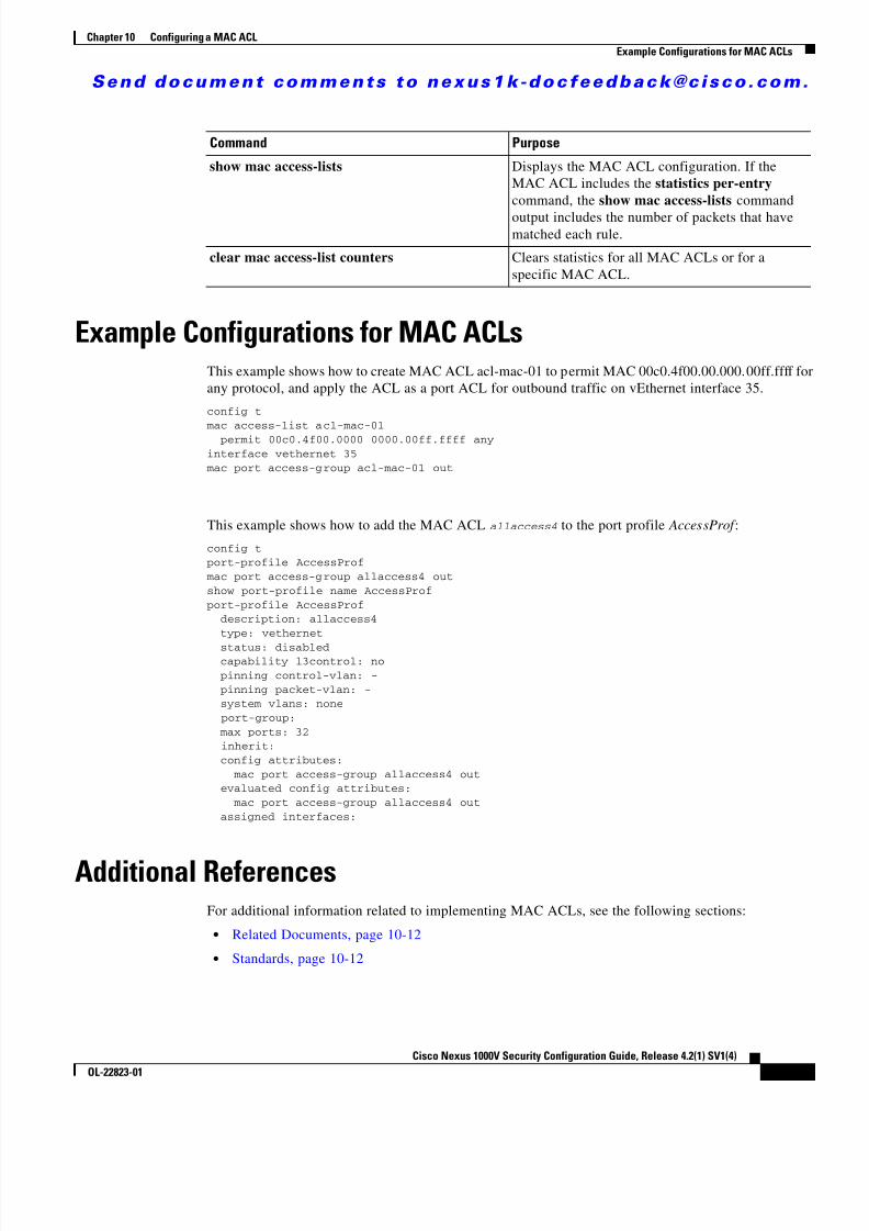
8/13/2019 n1000v Security
http://slidepdf.com/reader/full/n1000v-security 159/234
S e n d d o c u m e n t c o m m e n t s t o n e x u s 1 k - d o c f e e d b a c k @ c i s c o . c o m .
10-11Cisco Nexus 1000V Security Configuration Guide, Release 4.2(1) SV1(4)
OL-22823-01
Chapter 10 Configuring a MAC ACLExample Configurations for MAC ACLs
Example Configurations for MAC ACLsThis example shows how to create MAC ACL acl-mac-01 to permit MAC 00c0.4f00.00.000.00ff.ffff forany protocol, and apply the ACL as a port ACL for outbound traffic on vEthernet interface 35.
config t
mac access-list acl-mac-01 permit 00c0.4f00.0000 0000.00ff.ffff anyinterface vethernet 35
mac port access-group acl-mac-01 out
This example shows how to add the MAC ACL allaccess4 to the port profile AccessProf :
config tport-profile AccessProf
mac port access-group allaccess4 outshow port-profile name AccessProfport-profile AccessProf description: allaccess4
type: vethernet
status: disabled capability l3control: no pinning control-vlan: - pinning packet-vlan: - system vlans: none port-group: max ports: 32 inherit: config attributes: mac port access-group allaccess4 out evaluated config attributes: mac port access-group allaccess4 out assigned interfaces:
Additional ReferencesFor additional information related to implementing MAC ACLs, see the following sections:
• Related Documents, page 10-12
• Standards, page 10-12
Command Purpose
show mac access-lists Displays the MAC ACL configuration. If theMAC ACL includes the statistics per-entrycommand, the show mac access-lists commandoutput includes the number of packets that havematched each rule.
clear mac access-list counters Clears statistics for all MAC ACLs or for aspecific MAC ACL.

8/13/2019 n1000v Security
http://slidepdf.com/reader/full/n1000v-security 160/234
S e n d d o c u m e n t c o m m e n t s t o n e x u s 1 k - d o c f e e d b a c k @ c i s c o . c o m .
10-12Cisco Nexus 1000V Security Configuration Guide, Release 4.2(1) SV1(4)
OL-22823-01
Chapter 10 Configuring a MAC ACLFeature History for MAC ACL
Related Documents
Standards
Feature History for MAC ACLThis section provides the MAC ACL release history.
Related Topic Document Title
ACL concepts. Information About ACLs, page 9-1
Configuring interfaces. Cisco Nexus 1000V Interface Configuration Guide, Release4.2(1)SV1(4)
Configuring port profiles. Cisco Nexus 1000V Port Profile Configuration Guide, Release4.2(1)SV1(4)
Complete command syntax, command modes,command history, defaults, usage guidelines, andexamples for all Cisco Nexus 1000V commands.
Cisco Nexus 1000V Command Reference, Release 4.2(1)SV1(4)
Standards Title
No new or modified standards are supported by thisfeature, and support for existing standards has not beenmodified by this feature.
—
Feature Name Releases Feature Information
MAC ACL 4.0(4)SV1(1) This feature was introduced.

8/13/2019 n1000v Security
http://slidepdf.com/reader/full/n1000v-security 161/234
C H A P T E R
S e n d d o c u m e n t c o m m e n t s t o n e x u s 1 k - d o c f e e d b a c k @ c i s c o . c o m .
11-1Cisco Nexus 1000V Security Configuration Guide, Release 4.2(1) SV1(4)
OL-22823-01
11Configuring Port Security
This chapter describes how to configure port security and includes the following sections:
• Information About Port Security, page 11-1
• Guidelines and Limitations, page 11-5
• Additional References, page 11-19
• Configuring Port Security, page 11-6
• Verifying the Port Security Configuration, page 11-18
• Displaying Secure MAC Addresses, page 11-18
• Example Configuration for Port Security, page 11-18
• Additional References, page 11-19
• Feature History for Port Security, page 11-19
Information About Port SecurityPort security lets you configure Layer 2 interfaces permitting inbound traffic from a restricted, securedset of MAC addresses. Traffic from secured MAC addresses is not allowed on another interface withinthe same VLAN. The number of MAC addresses that can be secured is configured per interface.
This section includes the following topics:
• Secure MAC Address Learning, page 11-1
• Dynamic Address Aging, page 11-2
• Secure MAC Address Maximums, page 11-3
• Security Violations and Actions, page 11-4
• Port Security and Port Types, page 11-5
Secure MAC Address LearningThe process of securing a MAC address is called learning. The number of addresses that can be learnedis restricted, as described in the “Secure MAC Address Maximums” section on page 11-3 . Addresslearning can be accomplished using the following methods on any interface where port security isenabled:
• Static Method, page 11-2

8/13/2019 n1000v Security
http://slidepdf.com/reader/full/n1000v-security 162/234
S e n d d o c u m e n t c o m m e n t s t o n e x u s 1 k - d o c f e e d b a c k @ c i s c o . c o m .
11-2Cisco Nexus 1000V Security Configuration Guide, Release 4.2(1) SV1(4)
OL-22823-01
Chapter 11 Configuring Port SecurityInformation About Port Security
• Dynamic Method, page 11-2 (the default method)
• Sticky Method, page 11-2
Static Method
The static learning method lets you manually add or remove secure MAC addresses in the configurationof an interface.
A static secure MAC address entry remains in the configuration of an interface until you explicitlyremove it. For more information, see the “Removing a Static or a Sticky Secure MAC Address from anInterface” section on page 11-10 .
Adding secure addresses by the static method is not affected by whether dynamic or sticky addresslearning is enabled.
Dynamic Method
By default, when you enable port security on an interface, you enable the dynamic learning method. With
this method, the device secures MAC addresses as ingress traffic passes through the interface. If theaddress is not yet secured and the device has not reached any applicable maximum, it secures the addressand allows the traffic.
Dynamic addresses are aged and dropped once the age limit is reached, as described in the “DynamicAddress Aging” section on page 11-2 .
Dynamic addresses do not persist through restarts.
To remove a specific address learned by the dynamic method or to remove all addresses learned by thedynamic method on a specific interface, see the “Removing a Dynamic Secure MAC Address” sectionon page 11-11 .
Sticky Method
If you enable the sticky method, the device secures MAC addresses in the same manner as dynamic address learning. These addresses can be made persistent through a reboot by copying therunning-configuration to the startup-configuration, copy run start .
Dynamic and sticky address learning are mutually exclusive. When you enable sticky learning on aninterface, dynamic learning is stopped and sticky learning is used instead. If you disable sticky learning,dynamic learning is resumed.
Sticky secure MAC addresses are not aged.
To remove a specific address learned by the sticky method, see the “Removing a Static or a Sticky SecureMAC Address from an Interface” section on page 11-10 .
Dynamic Address AgingMAC addresses learned by the dynamic method are aged and dropped when reaching the age limit. Youcan configure the age limit on each interface. The range is from 0 to 1440 minutes, where 0 disablesaging.
There are two methods of determining address age:

8/13/2019 n1000v Security
http://slidepdf.com/reader/full/n1000v-security 163/234
S e n d d o c u m e n t c o m m e n t s t o n e x u s 1 k - d o c f e e d b a c k @ c i s c o . c o m .
11-3Cisco Nexus 1000V Security Configuration Guide, Release 4.2(1) SV1(4)
OL-22823-01
Chapter 11 Configuring Port SecurityInformation About Port Security
• Inactivity—The length of time after the device last received a packet from the address on theapplicable interface.
• Absolute—The length of time after the device learned the address. This is the default aging method;however, the default aging time is 0 minutes, which disables aging.
Secure MAC Address MaximumsThe secure MAC addresses on a secure port are inserted in the same MAC address table as other regularMACs. If a MAC table has reached its limit, then it will not learn any new secure MACs for that VLAN.
Figure 11-1 shows that each VLAN in a VEM has a forwarding table that can store a maximum numberof secure MAC addresses. For current MAC address maximums, see Security Configuration Limits,page 16-1 .
Figure 11-1 Secure MAC Addresses per VEM
Interface Secure MAC Addresses
By default, an interface can have only one secure MAC address. You can configure the maximum numberof MAC addresses permitted per interface or per VLAN on an interface. Maximums apply to secureMAC addresses learned by any method: dynamic, sticky, or static.
Tip To make use of the full bandwidth of the port, set the maximum number of addresses to one and configure
the MAC address of the attached device.
The following limits can determine how many secure MAC address are permitted on an interface:
• Device maximum—The device has a nonconfigurable limit of 8192 secure MAC addresses. Iflearning a new address would violate the device maximum, the device does not permit the newaddress to be learned, even if the interface or VLAN maximum has not been reached.
VEM 3VLAN 1 VLAN 2 ......... VLAN n
MACtable
MACtable
MACtable
MACtable
VEM 4VLAN 1 VLAN 2 ......... VLAN n
MACtable
MACtable
MACtable
MACtable
VEM 5VLAN 1 VLAN 2 ......... VLAN n
MACtable MACtable MACtable MACtable 1 9 6 1 5 0

8/13/2019 n1000v Security
http://slidepdf.com/reader/full/n1000v-security 164/234
S e n d d o c u m e n t c o m m e n t s t o n e x u s 1 k - d o c f e e d b a c k @ c i s c o . c o m .
11-4Cisco Nexus 1000V Security Configuration Guide, Release 4.2(1) SV1(4)
OL-22823-01
Chapter 11 Configuring Port SecurityInformation About Port Security
• Interface maximum—You can configure a maximum number of secure MAC addresses for eachinterface protected by port security. The default interface maximum is one address. Interfacemaximums cannot exceed the device maximum.
• VLAN maximum—You can configure the maximum number of secure MAC addresses per VLANfor each interface protected by port security. A VLAN maximum cannot exceed the interface
maximum. VLAN maximums are useful only for trunk ports. There are no default VLANmaximums.
For an example of how VLAN and interface maximums interact, see the “Security Violations andActions” section on page 11-4 .
You can configure VLAN and interface maximums per interface, as needed; however, when the new limitis less than the applicable number of secure addresses, you must reduce the number of secure MACaddresses first. To remove dynamically learned addresses, see the “Removing a Dynamic Secure MACAddress” section on page 11-11 . To remove addresses learned by the sticky or static methods, see the“Removing a Static or a Sticky Secure MAC Address from an Interface” section on page 11-10 .
Security Violations and ActionsPort security triggers a security violation when either of the following occurs:
• Ingress traffic arrives at an interface from a nonsecure MAC address and learning the address wouldexceed the applicable maximum number of secure MAC addresses.
When an interface has both a VLAN maximum and an interface maximum configured, a violationoccurs when either maximum is exceeded. For example, consider the following on a single interfaceconfigured with port security: – VLAN 1 has a maximum of 5 addresses – The interface has a maximum of 10 addresses
A violation is detected when either of the following occurs:
– Five addresses are learned for VLAN 1 and inbound traffic from a sixth address arrives at theinterface in VLAN 1. – Ten addresses are learned on the interface and inbound traffic from an 11th address arrives at
the interface.
• Ingress traffic from a secure MAC address arrives at a different interface in the same VLAN as theinterface on which the address is secured.
Note After a secure MAC address is configured or learned on one secure port, the sequence ofevents that occurs when port security detects that secure MAC address on a different port inthe same VLAN is known as a MAC move violation.
When a security violation occurs on an interface, the action specified in its port security configurationis applied. The possible actions that the device can take are as follows:
• Shutdown—Shuts down the interface that received the packet triggering the violation. The interfaceis error disabled. This action is the default. After you reenable the interface, it retains its portsecurity configuration, including its secure MAC addresses.
You can use the errdisable global configuration command to configure the device to reenable theinterface automatically if a shutdown occurs, or you can manually reenable the interface by enteringthe shutdown and no shut down interface configuration commands.

8/13/2019 n1000v Security
http://slidepdf.com/reader/full/n1000v-security 165/234
S e n d d o c u m e n t c o m m e n t s t o n e x u s 1 k - d o c f e e d b a c k @ c i s c o . c o m .
11-5Cisco Nexus 1000V Security Configuration Guide, Release 4.2(1) SV1(4)
OL-22823-01
Chapter 11 Configuring Port SecurityGuidelines and Limitations
Example :n1000v(config)# errdisable recovery cause psecure-violationn1000v(config)# copy running-config startup-config (Optional)
• Protect—Prevents violations from occurring. Address learning continues until the maximumnumber of MAC addresses on the interface is reached, after which the device disables learning on
the interface and drops all ingress traffic from nonsecure MAC addresses.If a violation occurs because ingress traffic from a secure MAC address arrives at a different interfacethan the interface on which the address is secure, the action is applied on the interface that received thetraffic. A MAC Move Violation is triggered on the port seeing the MAC which is already secured onanother interface.
Port Security and Port TypesYou can configure port security only on Layer 2 interfaces. Details about port security and different typesof interfaces or ports are as follows:
• Access ports—You can configure port security on interfaces that you have configured as Layer 2
access ports. On an access port, port security applies only to the access VLAN. • Trunk ports—You can configure port security on interfaces that you have configured as Layer 2
trunk ports. VLAN maximums are not useful for access ports. The device allows VLAN maximumsonly for VLANs associated with the trunk port.
• SPAN ports—You can configure port security on SPAN source ports but not on SPAN destinationports.
• Ethernet Ports—Port security is not supported on Ethernet ports.
• Ethernet Port Channels—Port security is not supported on Ethernet port channels.
Result of Changing an Access Port to a Trunk Port
When you change an access port to a trunk port on a Layer 2 interface configured with port security, allsecure addresses learned by the dynamic method are dropped. The device to the native trunk VLANmoves the addresses learned by the static or sticky method.
Result of Changing a Trunk Port to an Access Port
When you change a trunk port to an access port on a Layer 2 interface configured with port security, allsecure addresses learned by the dynamic method are dropped. All configured and sticky MAC addressesare dropped if they are not on the native trunk VLAN and do not match the access VLAN configured forthe access port they are moving to.
Guidelines and LimitationsWhen configuring port security, follow these guidelines:
• Port security is not supported on the following: – Ethernet interfaces – Ethernet port-channel interfaces

8/13/2019 n1000v Security
http://slidepdf.com/reader/full/n1000v-security 166/234
S e n d d o c u m e n t c o m m e n t s t o n e x u s 1 k - d o c f e e d b a c k @ c i s c o . c o m .
11-6Cisco Nexus 1000V Security Configuration Guide, Release 4.2(1) SV1(4)
OL-22823-01
Chapter 11 Configuring Port SecurityDefault Settings
– Switched port analyzer (SPAN) destination ports
• Port security does not depend upon other features.
• Port security does not support 802.1X.
• Port Security cannot be configured on interfaces with existing static MACs.
• Port Security cannot be enabled on interfaces whose VLANs have an existing static MAC even if itis programmed on a different interface.
Default SettingsTable 11-1 lists the default settings for port security parameters.
Configuring Port SecurityThis section includes the following topics:
• Enabling or Disabling Port Security on a Layer 2 Interface, page 11-6
• Enabling or Disabling Sticky MAC Address Learning, page 11-8 • Adding a Static Secure MAC Address on an Interface, page 11-9
• Removing a Static or a Sticky Secure MAC Address from an Interface, page 11-10
• Removing a Dynamic Secure MAC Address, page 11-11
• Configuring a Maximum Number of MAC Addresses, page 11-12
• Configuring an Address Aging Type and Time, page 11-14
• Configuring a Security Violation Action, page 11-15
• Recovering Ports Disabled for Port Security Violations, page 11-17
Enabling or Disabling Port Security on a Layer 2 InterfaceUse this procedure to enable or disable port security on a Layer 2 interface. For more information aboutdynamic learning of MAC addresses, see the “Secure MAC Address Learning” section on page 11-1 .
Note You cannot enable port security on a routed interface.
Table 11-1 Default Port Security Parameters
Parameters Default
Interface Disabled
MAC address learning method Dynamic
Interface maximum number of secure MACaddresses
1
Security violation action Shutdown

8/13/2019 n1000v Security
http://slidepdf.com/reader/full/n1000v-security 167/234
S e n d d o c u m e n t c o m m e n t s t o n e x u s 1 k - d o c f e e d b a c k @ c i s c o . c o m .
11-7Cisco Nexus 1000V Security Configuration Guide, Release 4.2(1) SV1(4)
OL-22823-01
Chapter 11 Configuring Port SecurityConfiguring Port Security
BEFORE YOU BEGIN
Before beginning this procedure, you must know or do the following:
• You are logged in to the CLI in EXEC mode.
• By default, port security is disabled on all interfaces.
• Enabling port security on an interface also enables dynamic MAC address learning. If you want toenable sticky MAC address learning, you must also complete the steps in the “Enabling or DisablingSticky MAC Address Learning” section on page 11-8 .
SUMMARY STEPS
1. config t
2. interface type number
3. [no ] switchport port-security
4. show running-config port-security
5. copy running-config startup-config
DETAILED STEPS
Command Purpose
Step 1 config t
Example:n1000v# config tn1000v(config)#
Places you into CLI Global Configuration mode.
Step 2 interface type number
Example:n1000v(config)# interface vethernet 36n1000v(config-if)#
Places you into Interface Configuration mode forthe specified interface.
Step 3 [ no ] switchport port-security
Example:n1000v(config-if)# switchportport-security
Enables port security on the interface.
Using the no option disables port security on theinterface.
Step 4 show running-config port-security
Example:n1000v(config-if)# show running-configport-security
Displays the port security configuration.
Step 5 copy running-config startup-config
Example:n1000v(config-if)# copy running-configstartup-config
(Optional) Copies the running configuration to the
startup configuration.

8/13/2019 n1000v Security
http://slidepdf.com/reader/full/n1000v-security 168/234
S e n d d o c u m e n t c o m m e n t s t o n e x u s 1 k - d o c f e e d b a c k @ c i s c o . c o m .
11-8Cisco Nexus 1000V Security Configuration Guide, Release 4.2(1) SV1(4)
OL-22823-01
Chapter 11 Configuring Port SecurityConfiguring Port Security
Enabling or Disabling Sticky MAC Address LearningUse this procedure to disable or enable sticky MAC address learning on an interface.
BEFORE YOU BEGIN
Before beginning this procedure, you must know or do the following:
• You are logged in to the CLI in EXEC mode.
• Dynamic MAC address learning is the default on an interface.
• By default, sticky MAC address learning is disabled.
• Make sure that port security is enabled on the interface that you are configuring.– To verify the configuration, see the “Verifying the Port Security Configuration” section on
page 11-18 .– To enable port security on the interface, see the “Enabling or Disabling Port Security on a Layer
2 Interface” section on page 11-6 .
SUMMARY STEPS
1. config t
2. interface type number
3. [no ] switchport port-security mac-address sticky
4. show running-config port-security
5. copy running-config startup-config
DETAILED STEPS
Command Purpose
Step 1 config t
Example:n1000v# config tn1000v(config)#
Places you into CLI Global Configuration mode.

8/13/2019 n1000v Security
http://slidepdf.com/reader/full/n1000v-security 169/234
S e n d d o c u m e n t c o m m e n t s t o n e x u s 1 k - d o c f e e d b a c k @ c i s c o . c o m .
11-9Cisco Nexus 1000V Security Configuration Guide, Release 4.2(1) SV1(4)
OL-22823-01
Chapter 11 Configuring Port SecurityConfiguring Port Security
Adding a Static Secure MAC Address on an InterfaceUse this procedure to add a static secure MAC address on a Layer 2 interface.
BEFORE YOU BEGIN
Before beginning this procedure, you must know or do the following:
• You are logged in to the CLI in EXEC mode.
• By default, no static secure MAC addresses are configured on an interface.
• Determine if the interface maximum has been reached for secure MAC addresses (use the showport-security command).
• If needed, you can remove a secure MAC address. See one of the following: – “Removing a Static or a Sticky Secure MAC Address from an Interface” section on page 11-10 – “Removing a Dynamic Secure MAC Address” section on page 11-11 )
– “Configuring a Maximum Number of MAC Addresses” section on page 11-12 ).
• Make sure that port security is enabled on the interface that you are configuring.– To verify the configuration, see the “Verifying the Port Security Configuration” section on
page 11-18 .– To enable port security on the interface, see the “Enabling or Disabling Port Security on a Layer
2 Interface” section on page 11-6 .
SUMMARY STEPS
1. config t
2. interface type number
Step 2 interface type number
Example:n1000v(config)# interface vethernet 36n1000v(config-if)#
Places you into Interface Configuration mode forthe specified interface.
Step 3 [ no ] switchport port-security mac-addresssticky
Example:n1000v(config-if)# switchportport-security mac-address sticky
Enables sticky MAC address learning on theinterface.
Using the no option disables sticky MAC addresslearning.
Step 4 show running-config port-security
Example:n1000v(config-if)# show running-configport-security
Displays the port security configuration.
Step 5 copy running-config startup-config
Example:n1000v(config-if)# copy running-configstartup-config
(Optional) Copies the running configuration to thestartup configuration.
Command Purpose

8/13/2019 n1000v Security
http://slidepdf.com/reader/full/n1000v-security 170/234
S e n d d o c u m e n t c o m m e n t s t o n e x u s 1 k - d o c f e e d b a c k @ c i s c o . c o m .
11-10Cisco Nexus 1000V Security Configuration Guide, Release 4.2(1) SV1(4)
OL-22823-01
Chapter 11 Configuring Port SecurityConfiguring Port Security
3. [no ] switchport port-security mac-address address [vlan vlan-ID ]
4. show running-config port-security
5. copy running-config startup-config
DETAILED STEPS
Removing a Static or a Sticky Secure MAC Address from an InterfaceUse this procedure to remove a static or a sticky secure MAC address from a Layer 2 interface.
BEFORE YOU BEGIN
Before beginning this procedure, you must know or do the following:
• You are logged in to the CLI in EXEC mode.
• Make sure that port security is enabled on the interface that you are configuring.– To verify the configuration, see the “Verifying the Port Security Configuration” section on
page 11-18 .– To enable port security on the interface, see the “Enabling or Disabling Port Security on a Layer
2 Interface” section on page 11-6 .
Command Purpose
Step 1 config t
Example:n1000v# config tn1000v(config)#
Places you into CLI Global Configuration mode.
Step 2 interface type number
Example:n1000v(config)# interface vethernet 36n1000v(config-if)#
Places you into Interface Configuration mode forthe specified interface.
Step 3 [ no ] switchport port-security mac-addressaddress [ vlan vlan-ID ]
Example:n1000v(config-if)# switchportport-security mac-address 0019.D2D0.00AE
Configures a static MAC address for port securityon the current interface. Use the vlan keyword ifyou want to specify the VLAN that traffic from theaddress is allowed on.
Step 4 show running-config port-security
Example:n1000v(config-if)# show running-configport-security
Displays the port security configuration.
Step 5 copy running-config startup-config
Example:
n1000v(config-if)# copy running-configstartup-config
(Optional) Copies the running configuration to thestartup configuration.

8/13/2019 n1000v Security
http://slidepdf.com/reader/full/n1000v-security 171/234
S e n d d o c u m e n t c o m m e n t s t o n e x u s 1 k - d o c f e e d b a c k @ c i s c o . c o m .
11-11Cisco Nexus 1000V Security Configuration Guide, Release 4.2(1) SV1(4)
OL-22823-01
Chapter 11 Configuring Port SecurityConfiguring Port Security
SUMMARY STEPS
1. config t
2. interface type number
3. no switchport port-security mac-address address [vlan vlan-ID ]
4. show running-config port-security
5. copy running-config startup-config
DETAILED STEPS
Removing a Dynamic Secure MAC AddressUse this procedure to remove a dynamically learned, secure MAC address.
BEFORE YOU BEGINBefore beginning this procedure, you must know or do the following:
• You are logged in to the CLI in EXEC mode.
Command Purpose
Step 1 config t
Example:n1000v# config tn1000v(config)#
Places you into CLI Global Configuration mode.
Step 2 interface type number
Example:n1000v(config)# interface vethernet 36n1000v(config-if)#
Places you into Interface Configuration mode forthe specified interface.
Step 3 no switchport port-security mac-addressaddress
Example:n1000v(config-if)# no switchportport-security mac-address 0019.D2D0.00AE
Removes the MAC address from port security onthe current interface.
Step 4 show running-config port-security
Example:
n1000v(config-if)# show running-configport-security
Displays the port security configuration.
Step 5 copy running-config startup-config
Example:n1000v(config-if)# copy running-configstartup-config
(Optional) Copies the running configuration to thestartup configuration.
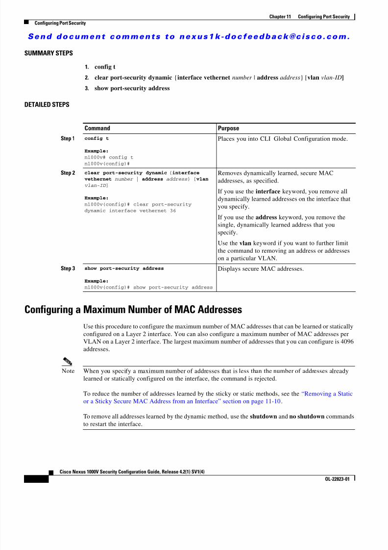
8/13/2019 n1000v Security
http://slidepdf.com/reader/full/n1000v-security 172/234
S e n d d o c u m e n t c o m m e n t s t o n e x u s 1 k - d o c f e e d b a c k @ c i s c o . c o m .
11-12Cisco Nexus 1000V Security Configuration Guide, Release 4.2(1) SV1(4)
OL-22823-01
Chapter 11 Configuring Port SecurityConfiguring Port Security
SUMMARY STEPS
1. config t
2. clear port-security dynamic {interface vethernet number | address address } [vlan vlan-ID ]
3. show port-security address
DETAILED STEPS
Configuring a Maximum Number of MAC AddressesUse this procedure to configure the maximum number of MAC addresses that can be learned or staticallyconfigured on a Layer 2 interface. You can also configure a maximum number of MAC addresses perVLAN on a Layer 2 interface. The largest maximum number of addresses that you can configure is 4096addresses.
Note When you specify a maximum number of addresses that is less than the number of addresses alreadylearned or statically configured on the interface, the command is rejected.
To reduce the number of addresses learned by the sticky or static methods, see the “Removing a Staticor a Sticky Secure MAC Address from an Interface” section on page 11-10 .
To remove all addresses learned by the dynamic method, use the shutdown and no shutdown commandsto restart the interface.
Command Purpose
Step 1 config t
Example:n1000v# config tn1000v(config)#
Places you into CLI Global Configuration mode.
Step 2 clear port-security dynamic { interface vethernet number | address address } [ vlan
vlan-ID ]
Example:n1000v(config)# clear port-securitydynamic interface vethernet 36
Removes dynamically learned, secure MACaddresses, as specified.
If you use the interface keyword, you remove alldynamically learned addresses on the interface thatyou specify.
If you use the address keyword, you remove thesingle, dynamically learned address that youspecify.
Use the vlan keyword if you want to further limitthe command to removing an address or addresseson a particular VLAN.
Step 3 show port-security address
Example:
n1000v(config)# show port-security address
Displays secure MAC addresses.

8/13/2019 n1000v Security
http://slidepdf.com/reader/full/n1000v-security 173/234
S e n d d o c u m e n t c o m m e n t s t o n e x u s 1 k - d o c f e e d b a c k @ c i s c o . c o m .
11-13Cisco Nexus 1000V Security Configuration Guide, Release 4.2(1) SV1(4)
OL-22823-01
Chapter 11 Configuring Port SecurityConfiguring Port Security
BEFORE YOU BEGIN
Before beginning this procedure, you must know or do the following:
• You are logged in to the CLI in EXEC mode.
• The Secure MACs share the L2 Forwarding Table (L2FT). The forwarding table for each VLAN can
hold up to 1024 entries.• By default, an interface has a maximum of one secure MAC address.
• VLANs have no default maximum number of secure MAC addresses.
• Make sure that port security is enabled on the interface that you are configuring.– To verify the configuration, see the “Verifying the Port Security Configuration” section on
page 11-18 .– To enable port security on the interface, see the “Enabling or Disabling Port Security on a Layer
2 Interface” section on page 11-6 .
SUMMARY STEPS
1. config t
2. interface type number
3. [no ] switchport port-security maximum number [vlan vlan-ID ]
4. show running-config port-security
5. copy running-config startup-config
DETAILED STEPS
Command Purpose
Step 1 config t
Example:n1000v# config tn1000v(config)#
Places you into CLI Global Configuration mode.
Step 2 interface type number
Example:n1000v(config)# interface vethernet 36n1000v(config-if)#
Places you into Interface Configuration mode forthe specified interface.
Step 3 [ no ] switchport port-security maximumnumber [ vlan vlan-ID ]
Example:n1000v(config-if)# switchportport-security maximum 425
Configures the maximum number of MACaddresses that can be learned or staticallyconfigured for the current interface. The highestvalid number is 4096. The no option resets themaximum number of MAC addresses to the default,which is 1.
If you want to specify the VLAN that the maximumapplies to, use the vlan keyword.

8/13/2019 n1000v Security
http://slidepdf.com/reader/full/n1000v-security 174/234
S e n d d o c u m e n t c o m m e n t s t o n e x u s 1 k - d o c f e e d b a c k @ c i s c o . c o m .
11-14Cisco Nexus 1000V Security Configuration Guide, Release 4.2(1) SV1(4)
OL-22823-01
Chapter 11 Configuring Port SecurityConfiguring Port Security
Configuring an Address Aging Type and TimeUse this procedure to configure the MAC address aging type and the length of time used to determinewhen MAC addresses learned by the dynamic method have reached their age limit.
BEFORE YOU BEGIN
Before beginning this procedure, you must know or do the following:
• You are logged in to the CLI in EXEC mode.
• By default, the aging time is 0 minutes, which disables aging.
• Absolute aging is the default aging type.
• Make sure that port security is enabled on the interface that you are configuring.– To verify the configuration, see the “Verifying the Port Security Configuration” section on
page 11-18 .– To enable port security on the interface, see the “Enabling or Disabling Port Security on a Layer
2 Interface” section on page 11-6 .
SUMMARY STEPS
1. config t
2. interface type number
3. [no ] switchport port-security aging type {absolute | inactivity }
4. [no ] switchport port-security aging time minutes
5. show running-config port-security
6. copy running-config startup-config
Step 4 show running-config port-security
Example:n1000v(config-if)# show running-configport-security
Displays the port security configuration.
Step 5 copy running-config startup-config
Example:n1000v(config-if)# copy running-configstartup-config
(Optional) Copies the running configuration to thestartup configuration.
Command Purpose
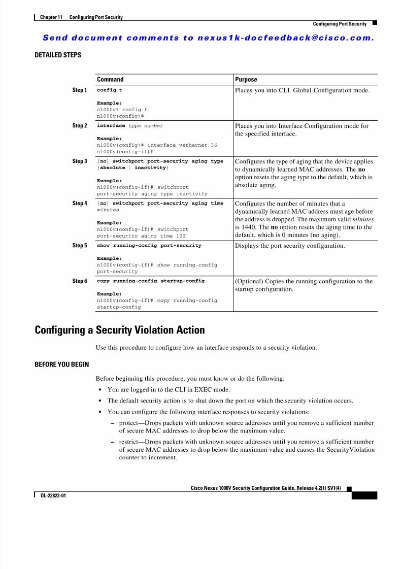
8/13/2019 n1000v Security
http://slidepdf.com/reader/full/n1000v-security 175/234
S e n d d o c u m e n t c o m m e n t s t o n e x u s 1 k - d o c f e e d b a c k @ c i s c o . c o m .
11-15Cisco Nexus 1000V Security Configuration Guide, Release 4.2(1) SV1(4)
OL-22823-01
Chapter 11 Configuring Port SecurityConfiguring Port Security
DETAILED STEPS
Configuring a Security Violation ActionUse this procedure to configure how an interface responds to a security violation.
BEFORE YOU BEGIN
Before beginning this procedure, you must know or do the following:
• You are logged in to the CLI in EXEC mode.
• The default security action is to shut down the port on which the security violation occurs.
• You can configure the following interface responses to security violations: – protect—Drops packets with unknown source addresses until you remove a sufficient number
of secure MAC addresses to drop below the maximum value. – restrict—Drops packets with unknown source addresses until you remove a sufficient number
of secure MAC addresses to drop below the maximum value and causes the SecurityViolationcounter to increment.
Command Purpose
Step 1 config t
Example:n1000v# config tn1000v(config)#
Places you into CLI Global Configuration mode.
Step 2 interface type number
Example:n1000v(config)# interface vethernet 36n1000v(config-if)#
Places you into Interface Configuration mode forthe specified interface.
Step 3 [ no ] switchport port-security aging type{ absolute | inactivity }
Example:n1000v(config-if)# switchportport-security aging type inactivity
Configures the type of aging that the device appliesto dynamically learned MAC addresses. The no option resets the aging type to the default, which isabsolute aging.
Step 4 [ no ] switchport port-security aging time minutes
Example:n1000v(config-if)# switchportport-security aging time 120
Configures the number of minutes that adynamically learned MAC address must age beforethe address is dropped. The maximum valid minutes is 1440. The no option resets the aging time to thedefault, which is 0 minutes (no aging).
Step 5 show running-config port-security
Example:n1000v(config-if)# show running-configport-security
Displays the port security configuration.
Step 6 copy running-config startup-config
Example:n1000v(config-if)# copy running-configstartup-config
(Optional) Copies the running configuration to thestartup configuration.

8/13/2019 n1000v Security
http://slidepdf.com/reader/full/n1000v-security 176/234
S e n d d o c u m e n t c o m m e n t s t o n e x u s 1 k - d o c f e e d b a c k @ c i s c o . c o m .
11-16Cisco Nexus 1000V Security Configuration Guide, Release 4.2(1) SV1(4)
OL-22823-01
Chapter 11 Configuring Port SecurityConfiguring Port Security
– shutdown—(the default) Puts the interface into the error-disabled state immediately and sendsan SNMP trap notification.
For more information, see the “Security Violations and Actions” section on page 11-4 .
• Make sure that port security is enabled on the interface that you are configuring.– To verify the configuration, see the “Verifying the Port Security Configuration” section on
page 11-18 .– To enable port security on the interface, see the “Enabling or Disabling Port Security on a Layer
2 Interface” section on page 11-6 .
SUMMARY STEPS
1. config t
2. interface type number
3. [no ] switchport port-security violation {protect | restrict | shutdown }
4. show running-config port-security
5. copy running-config startup-config
DETAILED STEPS
Command Purpose
Step 1 config t
Example:n1000v# config tn1000v(config)#
Places you into CLI Global Configuration mode.
Step 2 interface type number
Example:n1000v(config)# interface vethernet 36n1000v(config-if)#
Places you into Interface Configuration mode forthe specified interface.
Step 3 [ no ] switchport port-security violation { protect | restrict | shutdown }
Example:n1000v(config-if)# switchportport-security violation protect
Configures the security violation action for portsecurity on the current interface. The no optionresets the violation action to the default, which is toshut down the interface.
• protect : Drops packets with unknown sourceaddresses until you remove a sufficient numberof secure MAC addresses to drop below themaximum value.
• restrict : Drops packets with unknown source
addresses until you remove a sufficient numberof secure MAC addresses to drop below themaximum value and increments theSecurityViolation counter.
• shutdown : (the default) Puts the interface intothe error-disabled state immediately and sendsan SNMP trap notification.

8/13/2019 n1000v Security
http://slidepdf.com/reader/full/n1000v-security 177/234
S e n d d o c u m e n t c o m m e n t s t o n e x u s 1 k - d o c f e e d b a c k @ c i s c o . c o m .
11-17Cisco Nexus 1000V Security Configuration Guide, Release 4.2(1) SV1(4)
OL-22823-01
Chapter 11 Configuring Port SecurityConfiguring Port Security
Recovering Ports Disabled for Port Security ViolationsUse this procedure to automatically recover an interface disabled for port security violations.
BEFORE YOU BEGIN
Before beginning this procedure, you must know or do the following:
• You are logged in to the CLI in EXEC mode.
• To recover an interface manually from the error-disabled state, you must enter the shutdown command and then the no shutdown command .
• For more information, see the “Security Violations and Actions” section on page 11-4 .
SUMMARY STEPS
1. config t
2. interface type number
3. errdisable recovery cause psecure-violation
4. errdisable recovery interval seconds
5. show interface type number
DETAILED STEPS
Step 4 show running-config port-security
Example:n1000v(config-if)# show running-configport-security
Displays the port security configuration.
Step 5 copy running-config startup-config
Example:n1000v(config-if)# copy running-configstartup-config
(Optional) Copies the running configuration to thestartup configuration.
Command Purpose
Command Purpose
Step 1 config t
Example:n1000v# config tn1000v(config)#
Places you into CLI Global Configuration mode.
Step 2 interface type number
Example:n1000v(config)# interface vethernet 36n1000v(config-if)#
Places you into Interface Configuration mode forthe specified interface.
8/13/2019 n1000v Security
http://slidepdf.com/reader/full/n1000v-security 178/234
S e n d d o c u m e n t c o m m e n t s t o n e x u s 1 k - d o c f e e d b a c k @ c i s c o . c o m .
11-18Cisco Nexus 1000V Security Configuration Guide, Release 4.2(1) SV1(4)
OL-22823-01
Chapter 11 Configuring Port SecurityVerifying the Port Security Configuration
Verifying the Port Security ConfigurationUse the following commands to display the port security configuration information:
For detailed information about the fields in the output from this command, see the Cisco Nexus 1000VCommand Reference, Release 4.2(1)SV1(4) .
Displaying Secure MAC AddressesUse the show port-security address command to display secure MAC addresses. For detailedinformation about the fields in the output from this command, see the Cisco Nexus 1000V Command
Reference, Release 4 .2(1)SV1(4) .
Example Configuration for Port SecurityThe following example shows a port security configuration for vEthernet 36 interface with VLAN and
interface maximums for secure addresses. In this example, the interface is a trunk port. Additionally, theviolation action is set to Protect.
interface vethernet 36switchport port-security switchport port-security maximum 10 switchport port-security maximum 7 vlan 10 switchport port-security maximum 3 vlan 20 switchport port-security violation protect
Step 3 errdisable recovery cause psecure-violation
Example:n1000v(config-if)# errdisable recoverycause psecure-violation
Enables timed automatic recovery of the specifiedport that is disabled for port security violation.
Step 4 errdisable recovery interval seconds
Example:n1000v(config-if)# errdisable recoveryinterval 30
Configures a timer recovery interval in secondsfrom 30 to 65535 seconds.
Step 5 show interface type number
Example:n1000v(config-if)# show running-configport-security
Displays theinterface state for verification.
Command Purpose
Command Purpose
show running-config port-security Displays the port security configuration
show port-security Displays the port security status.
8/13/2019 n1000v Security
http://slidepdf.com/reader/full/n1000v-security 179/234
S e n d d o c u m e n t c o m m e n t s t o n e x u s 1 k - d o c f e e d b a c k @ c i s c o . c o m .
11-19Cisco Nexus 1000V Security Configuration Guide, Release 4.2(1) SV1(4)
OL-22823-01
Chapter 11 Configuring Port SecurityAdditional References
Additional ReferencesFor additional information related to implementing port security, see the following sections:
• Related Documents, page 11-19
• Standards, page 11-19
Related Documents
Standards
Feature History for Port SecurityThis section provides the port security feature release history.
Related Topic Document Title
Layer 2 switching Cisco Nexus 1000V Layer 2 Switching Configuration Guide, Release 4.2(1)SV1(4)
Port security commands: complete command syntax,command modes, command history, defaults, usageguidelines, and examples
Cisco Nexus 1000V Command Reference, Release 4.2(1)SV1(4)
Standards Title
No new or modified standards are supported by thisfeature, and support for existing standards has not beenmodified by this feature.
—
Feature Name Releases Feature Information
Port Security 4.0(4)SV1(1) This feature was introduced.

8/13/2019 n1000v Security
http://slidepdf.com/reader/full/n1000v-security 180/234
S e n d d o c u m e n t c o m m e n t s t o n e x u s 1 k - d o c f e e d b a c k @ c i s c o . c o m .
11-20Cisco Nexus 1000V Security Configuration Guide, Release 4.2(1) SV1(4)
OL-22823-01
Chapter 11 Configuring Port SecurityFeature History for Port Security

8/13/2019 n1000v Security
http://slidepdf.com/reader/full/n1000v-security 181/234
C H A P T E R
S e n d d o c u m e n t c o m m e n t s t o n e x u s 1 k - d o c f e e d b a c k @ c i s c o . c o m .
12-1Cisco Nexus 1000V Security Configuration Guide, Release 4.2(1) SV1(4)
OL-22823-01
12Configuring DHCP Snooping
This chapter describes how to configure Dynamic Host Configuration Protocol (DHCP) snooping andincludes the following sections:
• Information About DHCP Snooping, page 12-1
• Prerequisites for DHCP Snooping, page 12-3
• Guidelines and Limitations, page 12-3
• Default Settings, page 12-4
• Configuring DHCP Snooping, page 12-4
• Verifying the DHCP Snooping Configuration, page 12-16
• Monitoring DHCP Snooping, page 12-16
• Example Configuration for DHCP Snooping, page 12-16
• Additional References, page 12-17
• Feature History for DHCP Snooping, page 12-17
Information About DHCP SnoopingThis section includes the following topics:
• Overview, page 12-1
• Trusted and Untrusted Sources, page 12-2
• DHCP Snooping Binding Database, page 12-2
OverviewDHCP snooping acts like a firewall between untrusted hosts and trusted DHCP servers by doing thefollowing:
• Validates DHCP messages received from untrusted sources and filters out invalid response messagesfrom DHCP servers.
• Builds and maintains the DHCP snooping binding database, which contains information aboutuntrusted hosts with leased IP addresses.
• Uses the DHCP snooping binding database to validate subsequent requests from untrusted hosts.
8/13/2019 n1000v Security
http://slidepdf.com/reader/full/n1000v-security 182/234
S e n d d o c u m e n t c o m m e n t s t o n e x u s 1 k - d o c f e e d b a c k @ c i s c o . c o m .
12-2Cisco Nexus 1000V Security Configuration Guide, Release 4.2(1) SV1(4)
OL-22823-01
Chapter 12 Configuring DHCP SnoopingInformation About DHCP Snooping
Dynamic ARP inspection (DAI) and IP Source Guard also use information stored in the DHCP snoopingbinding database. For more information about these features, see Chapter 13, “Configuring DynamicARP Inspection” and Chapter 14, “Configuring IP Source Guard.”
DHCP snooping is enabled globally and per VLAN. By default, DHCP snooping is inactive on allVLANs. You can enable the feature on a single VLAN or a range of VLANs.
Trusted and Untrusted SourcesDHCP snooping identifies ports as trusted or untrusted. When you enable DHCP snooping, by defaultall vEthernet ports are untrusted and all ethernet ports (uplinks), port channels, special vEthernet ports(used by other features, such as VSD, for their operation) are trusted.You can configure whether DHCPtrusts traffic sources.
In an enterprise network, a trusted source is a device that is under your administrative control. Anydevice beyond the firewall or outside the network is an untrusted source. Generally, host ports are treatedas untrusted sources.
In a service provider environment, any device that is not in the service provider network is an untrustedsource (such as a customer switch). Host ports are untrusted sources.In the Cisco Nexus 1000V, you indicate that a source is trusted by configuring the trust state of itsconnecting interface. Uplink ports, as defined with the uplink capability on port profiles, are trusted andcannot be configured to be untrusted. This restriction prevents the uplink from being shut down for notconforming to rate limits or DHCP responses.
You can also configure other interfaces as trusted if they connect to devices (such as switches or routers)inside your network or if the administrator is running the DHCP server in a VM. You usually do notconfigure host port interfaces as trusted.
Note For DHCP snooping to function properly, all DHCP servers must be connected to the device throughtrusted interfaces.
DHCP Snooping Binding DatabaseUsing information extracted from intercepted DHCP messages, DHCP snooping dynamically builds andmaintains a database on each VEM. The database contains an entry for each untrusted host with a leasedIP address if the host is associated with a VLAN that has DHCP snooping enabled. The database doesnot contain entries for hosts connected through trusted interfaces.
Note The DHCP snooping binding database is also referred to as the DHCP snooping binding table.
DHCP snooping updates the database when the device receives specific DHCP messages. For example,the feature adds an entry to the database when the device receives a DHCPACK message from the server.The feature removes the entry in the database when the IP address lease expires or the device receives aDHCPRELEASE or DHCP DECLINE from the DHCP client or a DHCPNACK from the DHCP server.
Each entry in the DHCP snooping binding database includes the MAC address of the host, the leased IPaddress, the lease time, the binding type, and the VLAN number and interface information associatedwith the host.

8/13/2019 n1000v Security
http://slidepdf.com/reader/full/n1000v-security 183/234
S e n d d o c u m e n t c o m m e n t s t o n e x u s 1 k - d o c f e e d b a c k @ c i s c o . c o m .
12-3Cisco Nexus 1000V Security Configuration Guide, Release 4.2(1) SV1(4)
OL-22823-01
Chapter 12 Configuring DHCP SnoopingPrerequisites for DHCP Snooping
You can remove dynamically added entries from the binding database by using the clear ip dhcpsnooping binding command. For more information, see the “Clearing the DHCP Snooping BindingDatabase” section on page 12-13 .
Relay Agent Information OptionYou can configure DHCP to add the VSM MAC address and vEthernet port in the DHCP packet. This iscalled the DHCP Relay Agent Information Option, or Option 82, and is inserted by the DHCP relay agentwhen forwarding DHCP packets. Server administrators may use the information to implement IP addressassignment policies.
The relay agent identifies the following:
For detailed information about the Relay Agent Information Option, see RFC-3046, DHCP Relay Agent Information Option.
To configure the relay agent, see the “Relaying Switch and Circuit Information in DHCP” procedure onpage 12-15 .
High AvailabilityThe DHCP snooping binding table and all database entries created on the VEM are exported to the VSMand are persistent across VSM reboots.
Prerequisites for DHCP SnoopingDHCP snooping has the following prerequisites:
• You must be familiar with DHCP to configure DHCP snooping.
Guidelines and LimitationsDHCP snooping has the following configuration guidelines and limitations:
• A DHCP snooping database is stored on each VEM and can contain up to 1024 bindings.
• For seamless DHCP snooping, Virtual Service Domain (VSD) service VM ports are trusted ports bydefault. If you configure these ports as untrusted, this setting is ignored.
• If the VSM uses the VEM for connectivity (that is, the VSM has its VSM AIPC, management, andinband ports on a particular VEM), these virtual Ethernet interfaces must be configured as trustedinterfaces.
• The connecting interfaces on a device upstream from the Cisco Nexus 1000V must be configured astrusted if DHCP snooping is enabled on the device.
Information Option Description
circuit ID vEthernet port name
remote ID VSM MAC address

8/13/2019 n1000v Security
http://slidepdf.com/reader/full/n1000v-security 184/234
S e n d d o c u m e n t c o m m e n t s t o n e x u s 1 k - d o c f e e d b a c k @ c i s c o . c o m .
12-4Cisco Nexus 1000V Security Configuration Guide, Release 4.2(1) SV1(4)
OL-22823-01
Chapter 12 Configuring DHCP SnoopingDefault Settings
Default SettingsTable 12-1 lists the defaults for DHCP snooping.
Configuring DHCP SnoopingThis section includes the following topics:
• Minimum DHCP Snooping Configuration, page 12-4
• Enabling or Disabling the DHCP Feature, page 12-5
• Enabling or Disabling DHCP Snooping Globally, page 12-6
• Enabling or Disabling DHCP Snooping on a VLAN, page 12-7
• Enabling or Disabling DHCP Snooping MAC Address Verification, page 12-8
• Configuring an Interface as Trusted or Untrusted, page 12-9
• Configuring the Rate Limit for DHCP Packets, page 12-10
• Detecting Ports Disabled for DHCP Rate Limit Violation, page 12-11
• Recovering Ports Disabled for DHCP Rate Limit Violations, page 12-12
• Clearing the DHCP Snooping Binding Database, page 12-13
• Relaying Switch and Circuit Information in DHCP, page 12-15
Minimum DHCP Snooping ConfigurationThe minimum configuration for DHCP snooping is as follows:
Step 1 Enable the DHCP feature. For more information, see the “Enabling or Disabling the DHCP Feature”section on page 12-5 .
Step 2 Enable DHCP snooping globally. For more information, see the “Enabling or Disabling DHCP SnoopingGlobally” section on page 12-6 .
Step 3 Enable DHCP snooping on at least one VLAN. For more information, see the “Enabling or DisablingDHCP Snooping on a VLAN” section on page 12-7 .
Table 12-1 Default DHCP Snooping Parameters
Parameters Default
DHCP feature Disabled
DHCP snooping global Disabled
DHCP snooping VLAN Disabled
DHCP snooping MAC address verification Enabled
DHCP snooping trust Trusted for Ethernet interfaces, vEthernetinterfaces, and port channels, in the VSD feature.Untrusted for vEthernet interfaces notparticipating in the VSD feature.

8/13/2019 n1000v Security
http://slidepdf.com/reader/full/n1000v-security 185/234
S e n d d o c u m e n t c o m m e n t s t o n e x u s 1 k - d o c f e e d b a c k @ c i s c o . c o m .
12-5Cisco Nexus 1000V Security Configuration Guide, Release 4.2(1) SV1(4)
OL-22823-01
Chapter 12 Configuring DHCP SnoopingConfiguring DHCP Snooping
By default, DHCP snooping is disabled on all VLANs.
Step 4 Ensure that the DHCP server is connected to the device using a trusted interface. For more information,see the “Configuring an Interface as Trusted or Untrusted” section on page 12-9 .
Enabling or Disabling the DHCP FeatureUse this procedure to globally enable or disable the DHCP feature.
BEFORE YOU BEGIN
Before beginning this procedure, you must know or do the following:
• You are logged in to the CLI in EXEC mode.
• By default, DHCP is disabled.
SUMMARY STEPS
1. config t
2. feature dhcp
3. show feature
4. copy running-config startup-config
DETAILED STEPS
Command Purpose
Step 1 config t
Example:n1000v# config tn1000v(config)#
Enters global configuration mode.
Step 2 feature dhcp
Example:n1000v(config)# feature dhcp
Example:n1000v(config)# no feature dhcp
Enables DHCP snooping globally. The no optiondisables DHCP snooping but preserves an existingDHCP snooping configuration.

8/13/2019 n1000v Security
http://slidepdf.com/reader/full/n1000v-security 186/234
S e n d d o c u m e n t c o m m e n t s t o n e x u s 1 k - d o c f e e d b a c k @ c i s c o . c o m .
12-6Cisco Nexus 1000V Security Configuration Guide, Release 4.2(1) SV1(4)
OL-22823-01
Chapter 12 Configuring DHCP SnoopingConfiguring DHCP Snooping
Enabling or Disabling DHCP Snooping GloballyUse this procedure to globally enable or disable the DHCP snooping.
BEFORE YOU BEGIN
Before beginning this procedure, you must know or do the following:
• By default, DHCP snooping is globally disabled.
• If DHCP snooping is globally disabled, all DHCP snooping stops and no DHCP messages arerelayed.
• If you configure DHCP snooping and then globally disable it, the remaining configuration ispreserved.
SUMMARY STEPS
1. config t
2. [no ] ip dhcp snooping
3. show running-config dhcp
4. copy running-config startup-config
Step 3 show feature
Example:n1000v(config)# show featureFeature Name Instance State-------------------- -------- --------dhcp-snooping 1 enabledhttp-server 1 enabledlacp 1 enablednetflow 1 disabledport-profile-ro les 1 enabledprivate-vlan 1 disabledsshServer 1 enabledtacacs 1 enabledtelnetServer 1 enabledn1000v(config)#
Shows the state (enabled or disabled) of eachavailable feature.
Step 4 copy running-config startup-config
Example:n1000v(config)# copy running-configstartup-config
(Optional) Saves the running configurationpersistently through reboots and restarts by copying
it to the startup configuration.
Command Purpose
8/13/2019 n1000v Security
http://slidepdf.com/reader/full/n1000v-security 187/234
S e n d d o c u m e n t c o m m e n t s t o n e x u s 1 k - d o c f e e d b a c k @ c i s c o . c o m .
12-7Cisco Nexus 1000V Security Configuration Guide, Release 4.2(1) SV1(4)
OL-22823-01
Chapter 12 Configuring DHCP SnoopingConfiguring DHCP Snooping
DETAILED STEPS
Enabling or Disabling DHCP Snooping on a VLANUse this procedure to enable or disable DHCP snooping on one or more VLANs.
BEFORE YOU BEGIN
Before beginning this procedure, you must know or do the following:
• You are logged in to the CLI in EXEC mode.
• By default, DHCP snooping is disabled on all VLANs.
SUMMARY STEPS
1. config t
2. [no ] ip dhcp snooping vlan vlan-list
3. show running-config dhcp
4. copy running-config startup-config
Command Purpose
Step 1 config t
Example:n1000v# config tn1000v(config)#
Enters global configuration mode.
Step 2 [ no ] ip dhcp snooping
Example:n1000v(config)# ip dhcp snooping
Enables DHCP snooping globally. The no optiondisables DHCP snooping but preserves an existingDHCP snooping configuration.
Step 3 show running-config dhcp
Example:n1000v(config)# show running-config dhcp
Shows the DHCP snooping configuration.
Step 4 copy running-config startup-config
Example:n1000v(config)# copy running-configstartup-config
(Optional) Saves the running configurationpersistently through reboots and restarts by copying
it to the startup configuration.

8/13/2019 n1000v Security
http://slidepdf.com/reader/full/n1000v-security 188/234
S e n d d o c u m e n t c o m m e n t s t o n e x u s 1 k - d o c f e e d b a c k @ c i s c o . c o m .
12-8Cisco Nexus 1000V Security Configuration Guide, Release 4.2(1) SV1(4)
OL-22823-01
Chapter 12 Configuring DHCP SnoopingConfiguring DHCP Snooping
DETAILED STEPS
Enabling or Disabling DHCP Snooping MAC Address VerificationUse this procedure to enable or disable DHCP snooping MAC address verification. If the device receivesa packet on an untrusted interface and the source MAC address and the DHCP client hardware addressdo not match, address verification causes the device to drop the packet.
BEFORE YOU BEGIN
Before beginning this procedure, you must know or do the following:
• You are logged in to the CLI in EXEC mode.
• MAC address verification is enabled by default.
SUMMARY STEPS
1. config t
2. [no ] ip dhcp snooping verify mac-address
3. show running-config dhcp
4. copy running-config startup-config
Command Purpose
Step 1 config t
Example:n1000v# config tn1000v(config)#
Enters global configuration mode.
Step 2 [ no ] ip dhcp snooping vlan vlan-list
Example:n1000v(config)# ip dhcp snooping vlan100,200,250-252
Enables DHCP snooping on the VLANs specifiedby vlan-list . The no option disables DHCPsnooping on the VLANs specified.
Step 3 show running-config dhcp
Example:n1000v(config)# show running-config dhcp
Shows the DHCP snooping configuration.
Step 4 copy running-config startup-config
Example:n1000v(config)# copy running-configstartup-config
(Optional) Saves the running configuration
persistently through reboots and restarts by copyingit to the startup configuration.

8/13/2019 n1000v Security
http://slidepdf.com/reader/full/n1000v-security 189/234

8/13/2019 n1000v Security
http://slidepdf.com/reader/full/n1000v-security 190/234
S e n d d o c u m e n t c o m m e n t s t o n e x u s 1 k - d o c f e e d b a c k @ c i s c o . c o m .
12-10Cisco Nexus 1000V Security Configuration Guide, Release 4.2(1) SV1(4)
OL-22823-01
Chapter 12 Configuring DHCP SnoopingConfiguring DHCP Snooping
5. copy running-config startup-config
DETAILED STEPS
Configuring the Rate Limit for DHCP PacketsUse this procedure to configure a limit for the rate of DHCP packets per second received on each port.
BEFORE YOU BEGIN
Before beginning this procedure, you must know or do the following:
• You are logged in to the CLI in EXEC mode.
• Ports are put into an errdisabled state if they exceed the limit you set in this procedure for rate ofDHCP packets per second.
• You can configure the rate limit on either the interface or port profile.
SUMMARY STEPS
1. config t
2. interface vethernet interface-number
Command PurposeStep 1 config t
Example:n1000v# config tn1000v(config)#
Enters global configuration mode.
Step 2 interface vethernet interface-number
Example:n1000v(config)# interface vethernet 3n1000v(config-if)#
Enters interface configuration mode, whereinterface-number is the vEthernet interface that youwant to configure as trusted or untrusted for DHCPsnooping.
port-profile profilename
Example:
n1000v(config)# port-profile vm-datan1000v(config-port-prof)#
Enters port profile configuration mode for thespecified port profile, where profilename is aunique name of up to 80 characters.
Step 3 [ no ] ip dhcp snooping trust
Example:n1000v(config-if)# ip dhcp snooping trust
Configures the interface as a trusted interface forDHCP snooping. The no option configures the portas an untrusted interface.
Step 4 show running-config dhcp
Example:n1000v(config-if)# show running-configdhcp
Shows the DHCP snooping configuration.
Step 5 copy running-config startup-config
Example:
n1000v(config-if)# copy running-configstartup-config
(Optional) Saves the running configurationpersistently through reboots and restarts by copyingit to the startup configuration.

8/13/2019 n1000v Security
http://slidepdf.com/reader/full/n1000v-security 191/234
S e n d d o c u m e n t c o m m e n t s t o n e x u s 1 k - d o c f e e d b a c k @ c i s c o . c o m .
12-11Cisco Nexus 1000V Security Configuration Guide, Release 4.2(1) SV1(4)
OL-22823-01
Chapter 12 Configuring DHCP SnoopingConfiguring DHCP Snooping
port-profile profilename
3. [no] ip dhcp snooping limit rate rate
4. show running-config dhcp
5. copy running-config startup-config
DETAILED STEPS
Detecting Ports Disabled for DHCP Rate Limit ViolationUse this procedure to globally configure detection of ports disabled for exceeding the DHCP rate limit.
BEFORE YOU BEGIN
Before beginning this procedures, you must know or do the following:
• You are logged in to the CLI in EXEC mode.
• A failure to conform to the set rate causes the port to be put into an errdisable state.
• You must enter the shutdown command and then the no shutdown command to recover an interfacemanually from the error-disabled state.
Command Purpose
Step 1 config t
Example:n1000v# config tn1000v(config)#
Enters global configuration mode.
Step 2 interface vethernet interface-number
Example:n1000v(config)# interface vethernet 3n1000v(config-if)#
Enters interface configuration mode, whereinterface-number is the vEthernet interface forwhich you want to configure the DHCP packets per
second limit. port-profile profilename
Example:n1000v(config)# port-profile vm-datan1000v(config-port-prof)#
Enters port profile configuration mode for thespecified port profile, where profilename is aunique name of up to 80 characters.
Step 3 [ no ] ip dhcp snooping limit rate rate
Example:n1000v(config-port-prof)# ip dhcp snoopinglimit rate 30
Configures the limit for the rate of DHCP packetsper second (1 - 2048). The no option removes therate limit.
Step 4 show running-config dhcp
Example:n1000v(config-if)# show running-configdhcp
Shows the DHCP snooping configuration.
Step 5 copy running-config startup-config
Example:n1000v(config-if)# copy running-configstartup-config
(Optional) Saves the running configurationpersistently through reboots and restarts by copyingit to the startup configuration.

8/13/2019 n1000v Security
http://slidepdf.com/reader/full/n1000v-security 192/234
S e n d d o c u m e n t c o m m e n t s t o n e x u s 1 k - d o c f e e d b a c k @ c i s c o . c o m .
12-12Cisco Nexus 1000V Security Configuration Guide, Release 4.2(1) SV1(4)
OL-22823-01
Chapter 12 Configuring DHCP SnoopingConfiguring DHCP Snooping
SUMMARY STEPS
1. config t
2. [no] errdisable detect cause dhcp-rate-limit
3. show running-config dhcp
4. copy running-config startup-config
DETAILED STEPS
Recovering Ports Disabled for DHCP Rate Limit ViolationsUse this procedure to globally configure automatic recovery of ports disabled for violating the DHCPrate limit.
BEFORE YOU BEGIN
Before beginning this procedures, you must know or do the following:
• You are logged in to the CLI in EXEC mode.
• Ports that rate causes the port to be put into an errdisable state.
• You must enter the shutdown command and then the no shutdown command to recover an interfacemanually from the error-disabled state.
SUMMARY STEPS
1. config t
2. [no] errdisable recovery cause dhcp-rate-limit
3. errdisable recovery interval timer-interval
Command Purpose
Step 1 config t
Example:n1000v# config tn1000v(config)#
Enters global configuration mode.
Step 2 [no] errdisable detect causedhcp-rate-limit
Example:n1000v(config)# errdisable detect causedhcp-rate-limit
Enables DHCP error-disabled detection. The no
option disables DHCP error-disabled detection.
Step 3 show running-config dhcp
Example:n1000v(config)# show running-config dhcp
Shows the DHCP snooping configuration.
Step 4 copy running-config startup-config
Example:n1000v(config)# copy running-configstartup-config
(Optional) Saves the running configurationpersistently through reboots and restarts by copyingit to the startup configuration.

8/13/2019 n1000v Security
http://slidepdf.com/reader/full/n1000v-security 193/234

8/13/2019 n1000v Security
http://slidepdf.com/reader/full/n1000v-security 194/234
S e n d d o c u m e n t c o m m e n t s t o n e x u s 1 k - d o c f e e d b a c k @ c i s c o . c o m .
12-14Cisco Nexus 1000V Security Configuration Guide, Release 4.2(1) SV1(4)
OL-22823-01
Chapter 12 Configuring DHCP SnoopingConfiguring DHCP Snooping
2. show ip dhcp snooping binding
DETAILED STEPS
Clearing Binding Entries for an Interface
Use this procedure to remove binding entries for an interface from the DHCP snooping database.
BEFORE YOU BEGIN
Before beginning this procedures, you must know or do the following:
• You are logged in to the CLI in EXEC mode.
• You have the following information for the interface: – VLAN ID – IP address – MAC address
SUMMARY STEPS
1. clear ip dhcp snooping binding [{vlan vlan-id mac mac-addr ip ip-addr interface interface-id } |vlan vlan-id1 | interface interface-id1 ]
2. show ip dhcp snooping binding
DETAILED STEPS
Command PurposeStep 1 clear ip dhcp snooping binding
Example:n1000v# clear ip dhcp snooping binding
Clears dynamically added entries from the DHCPsnooping binding database.
Step 2 show ip dhcp snooping binding
Example:n1000v# show ip dhcp snooping binding
Displays the DHCP snooping binding database.
Command Purpose
Step 1 clear ip dhcp snooping binding [{ vlan vlan-id mac mac-addr ip ip-addr interface interface-id } | vlan vlan-id1 | interface
interface-id1 ]
Example:n1000v# clear ip dhcp snooping bindingvlan 10 mac EEEE.EEEE.EEEE ip 10.10.10.1interface vethernet 1
Clears dynamically added entries for an interfacefrom the DHCP snooping binding database.
Step 2 show ip dhcp snooping binding
Example:n1000v# show ip dhcp snooping binding
Displays the DHCP snooping binding database.

8/13/2019 n1000v Security
http://slidepdf.com/reader/full/n1000v-security 195/234
8/13/2019 n1000v Security
http://slidepdf.com/reader/full/n1000v-security 196/234
S e n d d o c u m e n t c o m m e n t s t o n e x u s 1 k - d o c f e e d b a c k @ c i s c o . c o m .
12-16Cisco Nexus 1000V Security Configuration Guide, Release 4.2(1) SV1(4)
OL-22823-01
Chapter 12 Configuring DHCP SnoopingVerifying the DHCP Snooping Configuration
Verifying the DHCP Snooping ConfigurationTo verify the DHCP snooping configuration, use the following commands:
For detailed information about these commands, see the Cisco Nexus 1000V Command Reference, Release 4.2(1)SV1(4) .
Monitoring DHCP SnoopingUse the show ip dhcp snooping statistics command to monitor DHCP snooping statistics. For detailedinformation about this command, see the Cisco Nexus 1000V Command Reference, Release4.2(1)SV1(4) .
Example Configuration for DHCP SnoopingThis example shows how to enable DHCP snooping on two VLANs, with vEthernet interface 5 trustedbecause the DHCP server is connected to that interface:
feature dhcp
interface vethernet 5ip dhcp snooping trustip dhcp snooping vlan 1, 50
Step 4 copy running-config startup-config
Example:n1000v(config)# copy running-configstartup-config
(Optional) Saves the running configurationpersistently through reboots and restarts by copyingit to the startup configuration.
Command Purpose
Command Purpose
show running-config dhcp Displays the DHCP snooping configuration
show ip dhcp snooping Displays general information about DHCPsnooping.
show ip dhcp snooping binding Display the contents of the DHCP snoopingbinding table.
show feature Displays the features available, such as DHCP,and whether they are enabled.

8/13/2019 n1000v Security
http://slidepdf.com/reader/full/n1000v-security 197/234
S e n d d o c u m e n t c o m m e n t s t o n e x u s 1 k - d o c f e e d b a c k @ c i s c o . c o m .
12-17Cisco Nexus 1000V Security Configuration Guide, Release 4.2(1) SV1(4)
OL-22823-01
Chapter 12 Configuring DHCP SnoopingAdditional References
Additional ReferencesFor additional information related to implementing DHCP snooping, see the following sections:
• Related Documents, page 12-17
• Standards, page 12-17
Related Documents
Standards
Feature History for DHCP SnoopingTable 12-2 lists the release history for this feature.
Related Topic Document Title
IP Source Guard Cisco Nexus 1000V Security Configuration Guide, Release4.2(1)SV1(4) , Chapter 14, “Configuring IP Source Guard”
Dynamic ARP Inspection Cisco Nexus 1000V Security Configuration Guide, Release4.2(1)SV1(4) , Chapter 13, “Configuring Dynamic ARP Inspection”
DHCP snooping commands: complete commandsyntax, command modes, command history, defaults,usage guidelines, and examples
Cisco Nexus 1000V Command Reference, Release 4.2(1)SV1(4)
Standards Title
RFC-2131 Dynamic Host Configuration Protocol (http://tools.ietf.org/html/rfc2131)
RFC-3046 DHCP Relay Agent Information Option
(http://tools.ietf.org/html/rfc3046)
Table 12-2 Feature History for DHCP Snooping
Feature Name Releases Feature Information
Relay Agent (Option 82) 4.2(1)SV1(4) You can configure relaying of VSM MAC and portinformation in DHCP packets.
feature dhcp command 4.2(1)SV1(4) Command added for enabling DHCP feature globally.
DHCP snooping 4.0(4)SV1(2) This feature was introduced.

8/13/2019 n1000v Security
http://slidepdf.com/reader/full/n1000v-security 198/234
S e n d d o c u m e n t c o m m e n t s t o n e x u s 1 k - d o c f e e d b a c k @ c i s c o . c o m .
12-18Cisco Nexus 1000V Security Configuration Guide, Release 4.2(1) SV1(4)
OL-22823-01
Chapter 12 Configuring DHCP SnoopingFeature History for DHCP Snooping

8/13/2019 n1000v Security
http://slidepdf.com/reader/full/n1000v-security 199/234
C H A P T E R
S e n d d o c u m e n t c o m m e n t s t o n e x u s 1 k - d o c f e e d b a c k @ c i s c o . c o m .
13-1Cisco Nexus 1000V Security Configuration Guide, Release 4.2(1) SV1(4)
OL-22823-01
13Configuring Dynamic ARP Inspection
This chapter describes how to configure dynamic Address Resolution Protocol (ARP) inspection (DAI).
This chapter includes the following sections:
• Information About DAI, page 13-1
• Prerequisites for DAI, page 13-4
• Guidelines and Limitations, page 13-4
• Default Settings, page 13-5
• Configuring DAI, page 13-5
• Verifying the DAI Configuration, page 13-14
• Monitoring DAI, page 13-15
• Example DAI Configuration, page 13-15
• Additional References, page 13-17
• Feature History for DAI, page 13-18
Information About DAIThis section includes the following topics:
• About ARP, page 13-1
• About ARP Spoofing Attacks, page 13-2
• About DAI and ARP Spoofing, page 13-2
• Interface Trust and Network Security, page 13-3
About ARPARP provides IP communication within a Layer 2 broadcast domain by mapping an IP address to a MACaddress. For example, host B wants to send information to host A but does not have the MAC address ofhost A in its ARP cache. In ARP terms, host B is the sender and host A is the target.
To get the MAC address of host A, host B generates a broadcast message for all hosts within thebroadcast domain to obtain the MAC address associated with the IP address of host A. All hosts withinthe broadcast domain receive the ARP request, and host A responds with its MAC address.

8/13/2019 n1000v Security
http://slidepdf.com/reader/full/n1000v-security 200/234
S e n d d o c u m e n t c o m m e n t s t o n e x u s 1 k - d o c f e e d b a c k @ c i s c o . c o m .
13-2Cisco Nexus 1000V Security Configuration Guide, Release 4.2(1) SV1(4)
OL-22823-01
Chapter 13 Configuring Dynamic ARP InspectionInformation About DAI
About ARP Spoofing AttacksIn an ARP spoofing attack, a host allows an unsolicited ARP response to update its cache so that trafficis directed through the attacker until it is discovered and the information in the ARP cache is corrected.
An ARP spoofing attack can affect hosts, switches, and routers connected to your Layer 2 network bysending false information to their ARP caches. Figure 13-1 shows an example of ARP cache poisoning.
Figure 13-1 ARP Cache Poisoning
In Figure 13-1 , hosts A, B, and C are connected to the device on interfaces A, B, and C, all of which areon the same subnet. Their IP and MAC addresses are shown in parentheses. For example, host A uses IPaddress IA and MAC address MA.
When host A needs to send IP data to host B, it broadcasts an ARP request for the MAC addressassociated with IP address IB. When the device and host B receive the ARP request, they add a bindingto their ARP caches for a host with the IP address IA and a MAC address MA.
When host B responds, the device and host A update their ARP caches with a binding for a host with theIP address IB and the MAC address MB.
Host C can spoof host A and B by broadcasting the following forged ARP responses:
• one for a host with an IP address of IA and a MAC address of MC
• one for a host with the IP address of IB and a MAC address of MC.
Host B then uses MC as the destination MAC address for traffic that was intended for IA, which meansthat host C intercepts that traffic. Likewise, host A and the device use MC as the destination MACaddress for traffic intended for IB.
Because host C knows the authentic MAC addresses for IA and IB, it can forward the intercepted traffic.
About DAI and ARP SpoofingDAI is used to validate ARP requests and responses as follows:
• Intercepts all ARP requests and responses on untrusted ports.
• Verifies that a packet has a valid IP-to-MAC address binding before updating the ARP cache orforwarding the packet.
• Drops invalid ARP packets.
DAI can determine the validity of an ARP packet based on valid IP-to-MAC address bindings stored ina Dynamic Host Configuration Protocol (DHCP) snooping binding database. This database is built byDHCP snooping when it is enabled on the VLANs and on the device. It may also contain static entriesthat you have created.
A B
C
Host A(IA, MA)
Host B(IB, MB)
Host C (man-in-the-middle)(IC, MC) 1
1 1 7 5 0
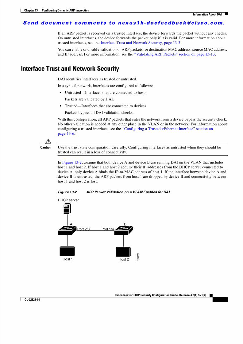
8/13/2019 n1000v Security
http://slidepdf.com/reader/full/n1000v-security 201/234
S e n d d o c u m e n t c o m m e n t s t o n e x u s 1 k - d o c f e e d b a c k @ c i s c o . c o m .
13-3Cisco Nexus 1000V Security Configuration Guide, Release 4.2(1) SV1(4)
OL-22823-01
Chapter 13 Configuring Dynamic ARP InspectionInformation About DAI
If an ARP packet is received on a trusted interface, the device forwards the packet without any checks.On untrusted interfaces, the device forwards the packet only if it is valid. For more information abouttrusted interfaces, see the Interface Trust and Network Security, page 13-3 .
You can enable or disable validation of ARP packets for destination MAC address, source MAC address,and IP address. For more information, see the “Validating ARP Packets” section on page 13-13 .
Interface Trust and Network SecurityDAI identifies interfaces as trusted or untrusted.
In a typical network, interfaces are configured as follows:
• Untrusted—Interfaces that are connected to hosts
Packets are validated by DAI.
• Trusted—Interfaces that are connected to devices
Packets bypass all DAI validation checks.
With this configuration, all ARP packets that enter the network from a device bypass the security check.No other validation is needed at any other place in the VLAN or in the network. For information aboutconfiguring a trusted interface, see the “Configuring a Trusted vEthernet Interface” section onpage 13-6 .
Caution Use the trust state configuration carefully. Configuring interfaces as untrusted when they should betrusted can result in a loss of connectivity.
In Figure 13-2 , assume that both device A and device B are running DAI on the VLAN that includeshost 1 and host 2. If host 1 and host 2 acquire their IP addresses from the DHCP server connected todevice A, only device A binds the IP-to-MAC address of host 1. If the interface between device A anddevice B is untrusted, the ARP packets from host 1 are dropped by device B and connectivity betweenhost 1 and host 2 is lost.
Figure 13-2 ARP Packet Validation on a VLAN Enabled for DAI
DHCP server
A B
Host 1 Host 2
Port 2/3 Port 1/4
1 8 6 6 9 4
8/13/2019 n1000v Security
http://slidepdf.com/reader/full/n1000v-security 202/234
S e n d d o c u m e n t c o m m e n t s t o n e x u s 1 k - d o c f e e d b a c k @ c i s c o . c o m .
13-4Cisco Nexus 1000V Security Configuration Guide, Release 4.2(1) SV1(4)
OL-22823-01
Chapter 13 Configuring Dynamic ARP InspectionPrerequisites for DAI
If you configure interfaces as trusted when they should be untrusted, you may open a security hole in anetwork. If device A is not running DAI, host 1 can easily poison the ARP cache of device B (and host 2,if you configured the link between the devices as trusted). This condition can occur even though device Bis running DAI.
DAI ensures that hosts (on untrusted interfaces) connected to a device that runs DAI do not poison the
ARP caches of other hosts in the network; however, DAI does not prevent hosts in other portions of thenetwork from poisoning the caches of the hosts that are connected to a device that runs DAI.
Note Depending on your network setup, you may not be able to validate a given ARP packet on all devices inthe VLAN.
Prerequisites for DAIThe following are prerequisite to configuring DAI.
• You are familiar with the following: – ARP
For more information, see IETF Standard RFC-826, An Ethernet Address Resolution Protocol (http://tools.ietf.org/html/rfc826).
– DHCP Snooping
For more information, see Configuring DHCP Snooping, page 12-1 .
• The software running on your Cisco Nexus 1000V supports DAI.
• The VEM feature level is updated to a release that supports DAI.
For more information about setting the VEM feature level, see the Cisco Nexus 1000V SoftwareUpgrade Guide, Release 4.2(1)SV1(4) .
Guidelines and LimitationsDAI has the following configuration guidelines and limitations:
• DAI is an ingress security feature and does not perform any egress checking.
• DAI is not effective when the host is connected to a device that does not support DAI or that doesnot have DAI enabled. To prevent attacks that are limited to a single Layer 2 broadcast domain, youshould separate a domain with DAI from those without DAI. This separation secures the ARP cachesof hosts in the domain with DAI.
• DAI verifies IP-to-MAC address bindings in incoming ARP requests and ARP responses. If you
have not configured static entries, then DHCP snooping must be enabled on the same VLANs onwhich you configure DAI. For more information, see the “Configuring DHCP Snooping” section onpage 12-4 .

8/13/2019 n1000v Security
http://slidepdf.com/reader/full/n1000v-security 203/234
S e n d d o c u m e n t c o m m e n t s t o n e x u s 1 k - d o c f e e d b a c k @ c i s c o . c o m .
13-5Cisco Nexus 1000V Security Configuration Guide, Release 4.2(1) SV1(4)
OL-22823-01
Chapter 13 Configuring Dynamic ARP InspectionDefault Settings
• DAI is supported on vEthernet interfaces and private VLAN ports.
• If you want DAI to use dynamic IP-MAC address bindings to determine if ARP packets are valid,ensure that DHCP snooping is configured. For more information, see the “Configuring DHCPSnooping” section on page 12-4 ).
• Virtual Service Domain (VSD) service VM ports are trusted ports by default. Even if you configureVSD ports as untrusted, they still appear as trusted ports to DAI.
Default SettingsTable 13-1 lists the DAI defaults.
Configuring DAIThis section includes the following topics:
• Configuring a VLAN for DAI, page 13-6
• Configuring a Trusted vEthernet Interface, page 13-6
• Resetting a vEthernet Interface to Untrusted, page 13-8
• Configuring DAI Rate Limits, page 13-9 • Resetting DAI Rate Limits to Default Values, page 13-11
• Detecting and Recovering Error-Disabled Interfaces, page 13-12
• Validating ARP Packets, page 13-13
Table 13-1 Default DAI Settings
Parameters Default
VLAN VLANs are not configured for DAI.
Trust state of vEthernet interfaces not in a VSD UntrustedTrust state of vEthernet Interfaces in a VSD Trusted
Trust state of Ethernet port channels Trusted
Incoming ARP packet rate limit for untrustedinterfaces
15 packets per second (pps)
Incoming ARP packet rate limit for trustedinterfaces
Unlimited
Rate limit burst interval 1 second
Detecting and Recovering DAI error-disabledinterfaces
Error-disabled detection and recovery is notconfigured.
Validation checks No checks are performed.VLAN statistics ARP request and response statistics.

8/13/2019 n1000v Security
http://slidepdf.com/reader/full/n1000v-security 204/234
S e n d d o c u m e n t c o m m e n t s t o n e x u s 1 k - d o c f e e d b a c k @ c i s c o . c o m .
13-6Cisco Nexus 1000V Security Configuration Guide, Release 4.2(1) SV1(4)
OL-22823-01
Chapter 13 Configuring Dynamic ARP InspectionConfiguring DAI
Configuring a VLAN for DAIUse this procedure to configure a VLAN or a list of VLANs for DAI.
BEFORE YOU BEGIN
Before beginning this procedure, you must know or do the following:
• You are logged in to the CLI in EXEC mode.
• By default, VLANs are not configured for DAI.
• You have already enabled DHCP snooping. For more information, see the “Enabling or Disablingthe DHCP Feature” section on page 12-5 .
• You know which VLANs you want to configure for DAI and they have already been created.
SUMMARY STEPS
1. config t
2. [no ] ip arp inspection vlan list 3. show ip arp inspection vlan list
4. copy running-config startup-config
DETAILED STEPS
Configuring a Trusted vEthernet InterfaceUse this procedure to configure a trusted vEthernet interface.
Command Purpose
Step 1 config t
Example:switch# config t
switch(config)#
Places you into the CLI Global Configurationmode.
Step 2 ip arp inspection vlan list
Example:switch(config)# ip arp inspection vlan 13
Configures the specified VLAN or list of VLANs forDAI.
Step 3 show ip arp inspection vlan list
Example:switch(config)# show ip arp inspectionvlan 13
(Optional) Shows the DAI status for the specifiedlist of VLANs.
Step 4 copy running-config startup-config
Example:switch(config-if)# copy running-configstartup-config
(Optional) Saves the running configurationpersistently through reboots and restarts by copyingit to the startup configuration.

8/13/2019 n1000v Security
http://slidepdf.com/reader/full/n1000v-security 205/234
S e n d d o c u m e n t c o m m e n t s t o n e x u s 1 k - d o c f e e d b a c k @ c i s c o . c o m .
13-7Cisco Nexus 1000V Security Configuration Guide, Release 4.2(1) SV1(4)
OL-22823-01
Chapter 13 Configuring Dynamic ARP InspectionConfiguring DAI
BEFORE YOU BEGIN
Before beginning this procedure, you must know or do the following:
• You are logged in to the CLI in EXEC mode.
• By default, vEthernet interfaces are untrusted, unless they are part of a VSD.
• If an interface is untrusted, all ARP requests and responses are verified for a valid IP-MAC addressbinding before the local cache is updated and the packet forwarded. If a packet has an invalidIP-MAC address binding, it is dropped.
• ARP packets received on a trusted interface are forwarded but not checked.
• You can configure a trusted interface on either of the following: – the interface, itself – the existing port profile that the interface is assigned to
If configuring a trusted interface on the port profile, it has already been created and you knowits name.
SUMMARY STEPS1. config t
2. interface vethernet interface-number
port-profile profilename
3. [no ] ip arp inspection trust
4. show ip arp inspection interface type slot / number
show port-profile profilename
5. copy running-config startup-config
DETAILED STEPS
Command Purpose
Step 1 config t
Example:switch# config tswitch(config)#
Places you into the CLI Global Configurationmode.
Step 2 interface vethernet interface-number
Example:switch(config)# interface vethernet 3switch(config-if)#
Places you into the CLI Interface Configurationmode, for the specified vEthernet interface.
port-profile profilenameExample:switch(config)# port-profile vm-dataswitch(config-port-prof)#
Places you into the CLI Port Profile Configurationmode for the specified port profile.
Step 3 ip arp inspection trust
Example:switch(config-if)# ip arp inspection trust
Configures the interface as a trusted ARP interface.

8/13/2019 n1000v Security
http://slidepdf.com/reader/full/n1000v-security 206/234
S e n d d o c u m e n t c o m m e n t s t o n e x u s 1 k - d o c f e e d b a c k @ c i s c o . c o m .
13-8Cisco Nexus 1000V Security Configuration Guide, Release 4.2(1) SV1(4)
OL-22823-01
Chapter 13 Configuring Dynamic ARP InspectionConfiguring DAI
Resetting a vEthernet Interface to UntrustedUse this procedure to remove a trusted designation from a vEthernet interface, returning it to the defaultuntrusted designation.
BEFORE YOU BEGIN
Before beginning this procedure, you must know or do the following:
• You are logged in to the CLI in EXEC mode.
• By default, vEthernet interfaces are untrusted, unless they are part of a VSD. • If an interface is untrusted, all ARP requests and responses are verified for a valid IP-MAC address
binding before the local cache is updated and the packet forwarded. If a packet has an invalidIP-MAC address binding, it is dropped.
SUMMARY STEPS
1. config t
2. interface vethernet interface-number
3. default ip arp inspection trust
4. show ip arp inspection interface type slot / number
5. copy running-config startup-config
ip arp inspection trust
Example:switch(config-port-prof)# ip arpinspection trust
Configures the interfaces assigned to the port profileas trusted ARP interfaces.
Step 4 show ip arp inspection interface vethernetinterface-number
Example:switch(config-if)# show ip arp inspectioninterface vethernet 2
(Optional) Displays the trusted state and the ARPpacket rate for the specified interface.
show port-profile profilename
Example:switch(config)# show port-profile vm-data
(Optional) Displays the port profile configurationincluding the ARP trusted state.
Step 5 copy running-config startup-config
Example:switch(config-if)# copy running-configstartup-config
(Optional) Saves the running configurationpersistently through reboots and restarts by copyingit to the startup configuration.
Command Purpose

8/13/2019 n1000v Security
http://slidepdf.com/reader/full/n1000v-security 207/234
S e n d d o c u m e n t c o m m e n t s t o n e x u s 1 k - d o c f e e d b a c k @ c i s c o . c o m .
13-9Cisco Nexus 1000V Security Configuration Guide, Release 4.2(1) SV1(4)
OL-22823-01
Chapter 13 Configuring Dynamic ARP InspectionConfiguring DAI
DETAILED STEPS
Configuring DAI Rate Limits
Use this procedure to set the rate limit of ARP requests and responses.
BEFORE YOU BEGIN
Before beginning this procedure, you must know or do the following:
• You are logged in to the CLI in EXEC mode.
• Because of their aggregation, trunk ports should be configured with higher rate limit.
• Once the rate of incoming packets exceeds the configured rate, the interface is automatically put intoan errdisable state.
• The default DAI rate limits are as follows: – Untrusted interfaces = 15 packets per second
– Trusted interfaces = unlimited– Burst interval = 1 second
• You can configure the rate limits for an interface on either of the following: – the interface, itself – the existing port profile that the interface is assigned to
If configuring the port profile, it has already been created and you know its name.
Command Purpose
Step 1 config t
Example:switch# config tswitch(config)#
Places you into the CLI Global Configuration
mode.
Step 2 interface vethernet interface-number
Example:switch(config)# interface vethernet 3switch(config-if)#
Places you into the CLI Interface Configurationmode, for the specified vEthernet interface.
Step 3 default ip arp inspection trust
Example:switch(config-if)# default ip arpinspection trust
Removes the trusted designation from the interfaceand returns it to the default untrusted state.
Step 4 show ip arp inspection interface vethernet
interface-number Example:switch(config-if)# show ip arp inspectioninterface vethernet 3
(Optional) Displays the trusted state and the ARP
packet rate for the specified interface.
Step 5 copy running-config startup-config
Example:switch(config-if)# copy running-configstartup-config
(Optional) Saves the running configurationpersistently through reboots and restarts by copyingit to the startup configuration.

8/13/2019 n1000v Security
http://slidepdf.com/reader/full/n1000v-security 208/234
S e n d d o c u m e n t c o m m e n t s t o n e x u s 1 k - d o c f e e d b a c k @ c i s c o . c o m .
13-10Cisco Nexus 1000V Security Configuration Guide, Release 4.2(1) SV1(4)
OL-22823-01
Chapter 13 Configuring Dynamic ARP InspectionConfiguring DAI
SUMMARY STEPS
1. config t
2. interface vethernet interface-number
port-profile profilename
3. ip arp inspection limit {rate pps [burst interval bint ] | none }
4. show running-config dhcp
5. copy running-config startup-config
DETAILED STEPS
Command Purpose
Step 1 config t
Example:switch# config tswitch(config)#
Places you into the CLI Global Configuration mode.
Step 2 interface vethernet interface-number
Example:switch(config)# interface vethernet 3switch(config-if)#
Places you into the CLI Interface Configurationmode, for the specified vEthernet interface.
port-profile profilename
Example:switch(config)# port-profile vm-dataswitch(config-port-prof)#
Places you into the CLI Port Profile configurationmode for the specified port profile.
Step 3 ip arp inspection limit {rate pps [burstinterval bint ] | none }
Example:switch(config-if)# ip arp inspection limitrate 30Example:switch(config-port-prof)# ip arpinspection limit rate 30
Configures the specified ARP inspection limit on theinterface or the port profile as follows:
• rate : allowable values are between 1 and 2048packets per second (pps)– Untrusted interface default = 15 packets per
second – Trusted interface default = unlimited
• burst interval : allowable values are between 1and 15 seconds (default = 1 second).
• none : unlimited number of packets per second
Step 4 show running-config dhcp
Example:switch(config)# show running-config dhcp
(Optional) Displays the DHCP snoopingconfiguration, including the DAI configuration.
Step 5 copy running-config startup-config
Example:switch(config)# copy running-configstartup-config
(Optional) Saves the running configurationpersistently through reboots and restarts by copyingit to the startup configuration.
8/13/2019 n1000v Security
http://slidepdf.com/reader/full/n1000v-security 209/234
S e n d d o c u m e n t c o m m e n t s t o n e x u s 1 k - d o c f e e d b a c k @ c i s c o . c o m .
13-11Cisco Nexus 1000V Security Configuration Guide, Release 4.2(1) SV1(4)
OL-22823-01
Chapter 13 Configuring Dynamic ARP InspectionConfiguring DAI
Resetting DAI Rate Limits to Default ValuesUse this procedure to set the rate limit of ARP requests and responses to the defaults, removing anyconfigured values.
BEFORE YOU BEGINBefore beginning this procedure, you must know or do the following:
• You are logged in to the CLI in EXEC mode.
• The default DAI rate limits are as follows: – Untrusted interfaces = 15 packets per second – Trusted interfaces = unlimited
– Burst interval = 1 second
• You can configure the rate limits for an interface on either of the following: – the interface, itself
– the existing port profile that the interface is assigned to
If configuring the port profile, it has already been created and you know its name.
SUMMARY STEPS
1. config t
2. interface vethernet interface-number
3. default ip arp inspection limit {rate pps [burst interval bint ] | none }
4. show running-config dhcp
5. copy running-config startup-config
DETAILED STEPS
Command Purpose
Step 1 config t
Example:switch# config tswitch(config)#
Places you into the CLI Global Configuration mode.
Step 2 interface vethernet interface-number
Example:switch(config)# interface vethernet 3
switch(config-if)#
Places you into the CLI Interface Configurationmode, for the specified vEthernet interface.

8/13/2019 n1000v Security
http://slidepdf.com/reader/full/n1000v-security 210/234
S e n d d o c u m e n t c o m m e n t s t o n e x u s 1 k - d o c f e e d b a c k @ c i s c o . c o m .
13-12Cisco Nexus 1000V Security Configuration Guide, Release 4.2(1) SV1(4)
OL-22823-01
Chapter 13 Configuring Dynamic ARP InspectionConfiguring DAI
Detecting and Recovering Error-Disabled InterfacesUse this procedure to configure the detection and recovery of error-disabled interfaces.
BEFORE YOU BEGIN
Before beginning this procedures, you must know or do the following:
• You are logged in to the CLI in EXEC mode.
• By default, interfaces are not configured for DAI error-disabled recovery.
• To manually recover an interface from the error-disabled state, use the following commandsequence.
1. shutdown
2. no shutdown
SUMMARY STEPS
1. config t
2. [no] errdisable detect cause arp-inspection
3. [no ] errdisable recovery cause arp-inspection
4. errdisable recovery interval timer-interval 5. show running-config | include errdisable
6. copy running-config startup-config
Step 3 default ip arp inspection limit {rate pps [burstinterval bint ] | none }
Example:switch(config-if)# default ip arp
inspection limit rate
Removes the configured DAI rate limits from theinterface and returns them to the default values.
• rate :
– Untrusted interface default = 15 packets persecond – Trusted interface default = unlimited
• burst interval : default = 1 second
• none : unlimited number of packets per second
Step 4 show running-config dhcp
Example:switch(config)# show running-config dhcp
(Optional) Displays the DHCP snoopingconfiguration, including the DAI rate limits.
Step 5 copy running-config startup-config
Example:switch(config)# copy running-configstartup-config
(Optional) Saves the running configurationpersistently through reboots and restarts by copyingit to the startup configuration.
Command Purpose
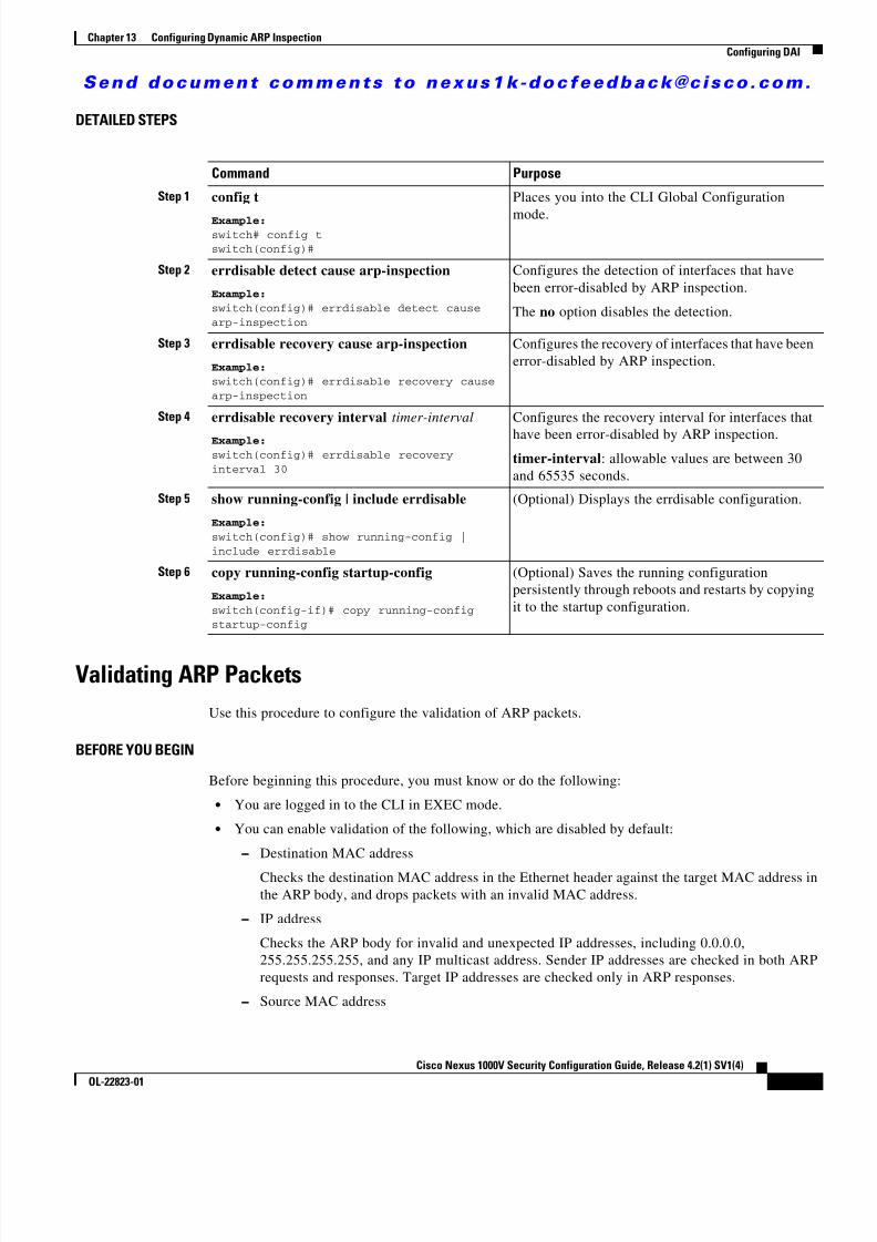
8/13/2019 n1000v Security
http://slidepdf.com/reader/full/n1000v-security 211/234
S e n d d o c u m e n t c o m m e n t s t o n e x u s 1 k - d o c f e e d b a c k @ c i s c o . c o m .
13-13Cisco Nexus 1000V Security Configuration Guide, Release 4.2(1) SV1(4)
OL-22823-01
Chapter 13 Configuring Dynamic ARP InspectionConfiguring DAI
DETAILED STEPS
Validating ARP PacketsUse this procedure to configure the validation of ARP packets.
BEFORE YOU BEGIN
Before beginning this procedure, you must know or do the following:
• You are logged in to the CLI in EXEC mode.
• You can enable validation of the following, which are disabled by default: – Destination MAC address
Checks the destination MAC address in the Ethernet header against the target MAC address inthe ARP body, and drops packets with an invalid MAC address.
– IP address
Checks the ARP body for invalid and unexpected IP addresses, including 0.0.0.0,255.255.255.255, and any IP multicast address. Sender IP addresses are checked in both ARPrequests and responses. Target IP addresses are checked only in ARP responses.
– Source MAC address
Command Purpose
Step 1 config t
Example:switch# config tswitch(config)#
Places you into the CLI Global Configuration
mode.
Step 2 errdisable detect cause arp-inspection
Example:switch(config)# errdisable detect causearp-inspection
Configures the detection of interfaces that havebeen error-disabled by ARP inspection.
The no option disables the detection.
Step 3 errdisable recovery cause arp-inspection
Example:switch(config)# errdisable recovery causearp-inspection
Configures the recovery of interfaces that have beenerror-disabled by ARP inspection.
Step 4 errdisable recovery interval timer-interval
Example:switch(config)# errdisable recoveryinterval 30
Configures the recovery interval for interfaces that
have been error-disabled by ARP inspection.timer-interval : allowable values are between 30and 65535 seconds.
Step 5 show running-config | include errdisable
Example:switch(config)# show running-config |include errdisable
(Optional) Displays the errdisable configuration.
Step 6 copy running-config startup-config
Example:switch(config-if)# copy running-configstartup-config
(Optional) Saves the running configurationpersistently through reboots and restarts by copyingit to the startup configuration.

8/13/2019 n1000v Security
http://slidepdf.com/reader/full/n1000v-security 212/234
S e n d d o c u m e n t c o m m e n t s t o n e x u s 1 k - d o c f e e d b a c k @ c i s c o . c o m .
13-14Cisco Nexus 1000V Security Configuration Guide, Release 4.2(1) SV1(4)
OL-22823-01
Chapter 13 Configuring Dynamic ARP InspectionVerifying the DAI Configuration
Checks the source MAC address in the Ethernet header against the sender MAC address in theARP body for ARP requests and responses, and drops packets with invalid MAC addresses.
• Whenever you configure a validation, any previous validation configuration is overwritten.
SUMMARY STEPS
1. config t
2. [no ] ip arp inspection validate {[src-mac ] [dst-mac ] [ ip ]}
3. show running-config dhcp
4. copy running-config startup-config
DETAILED STEPS
Verifying the DAI ConfigurationTo display and verify the DAI configuration, use the following commands:
Command Purpose
Step 1 config t
Example:switch# config tswitch(config)#
Places you into the CLI Global Configuration mode.
Step 2 ip arp inspection validate {[src-mac ][dst-mac ] [ ip ]}
Example:switch(config)# ip arp inspection validatesrc-mac dst-mac ip
Enables the specified validation and overwrites anyexisting validation that was previously saved:
• Source MAC
• Destination MAC
• IP
You can specify all three of these validations but youmust specify at least one.
Use the no option to disable a validation.Step 3 show running-config dhcp
Example:switch(config)# show running-config dhcp
(Optional) Displays the DHCP snoopingconfiguration, including the DAI configuration.
Step 4 copy running-config startup-config
Example:switch(config)# copy running-configstartup-config
(Optional) Saves the running configurationpersistently through reboots and restarts by copyingit to the startup configuration.
Command Purpose
show running-config dhcp Displays the DAI configuration.
show ip arp inspection Displays the status of DAI.

8/13/2019 n1000v Security
http://slidepdf.com/reader/full/n1000v-security 213/234
S e n d d o c u m e n t c o m m e n t s t o n e x u s 1 k - d o c f e e d b a c k @ c i s c o . c o m .
13-15Cisco Nexus 1000V Security Configuration Guide, Release 4.2(1) SV1(4)
OL-22823-01
Chapter 13 Configuring Dynamic ARP InspectionMonitoring DAI
For detailed information about command output, see the Cisco Nexus 1000V Command Reference, Release 4.2(1)SV1(4) .
Monitoring DAITo monitor DAI, use the following commands:
For detailed information about command output, see the Cisco Nexus 1000V Command Reference, Release 4.2(1)SV1(4) .
Example DAI ConfigurationThis example shows how to configure DAI in a network with two VEMs:
• One VEM is hosting an authentic web server and a DHCP server.
• The other VEM is hosting a client virtual machine (VM 1) and a virtual machine (VM 2) with arogue web server. VM 1 is connected to vEthernet interface 3, which is untrusted by default, andbelongs to VLAN 1. VM 2 is connected to vEthernet 10 and VLAN 1.
Without DAI enabled, VM 2 can spoof the ARP cache in VM 1 by sending a packet even though an ARPrequest was not generated. In this case, the packet directs VM 1 to send its traffic to the VM 2 web serverinstead of the authentic web server.
If DAI is enabled when VM2 attempts to spoof the ARP cache in VM1, the unsolicited ARP packet sentby VM 2 is dropped because DAI detects the invalid IP-to-MAC address binding. The attempt to spoofthe ARP cache fails, and VM 1 connects to the authentic web server.
Note DAI depends on the DHCP snooping database to verify IP-to-MAC address bindings in incoming ARPrequests and ARP responses. Make sure to enable DHCP snooping to permit ARP packets that havedynamically-assigned IP addresses. For configuration information, see Chapter 12, “Configuring DHCPSnooping.”
show ip arp inspection interface vethernetinterface-number
Displays the trust state and ARP packet rate for aspecific interface.
show ip arp inspection vlan vlan-ID Displays the DAI configuration for a specificVLAN.
Command Purpose
Command Purpose
show ip arp inspection statistics Displays DAI statistics.show ip arp inspection statistics vlan Displays DAI statistics for a specified VLAN.
clear ip arp inspection statistics Clears DAI statistics.

8/13/2019 n1000v Security
http://slidepdf.com/reader/full/n1000v-security 214/234
S e n d d o c u m e n t c o m m e n t s t o n e x u s 1 k - d o c f e e d b a c k @ c i s c o . c o m .
13-16Cisco Nexus 1000V Security Configuration Guide, Release 4.2(1) SV1(4)
OL-22823-01
Chapter 13 Configuring Dynamic ARP InspectionExample DAI Configuration
The following steps are used to configure DAI for this example:
Step 1 Enable DAI on VLAN 1 and verify the configuration.
n1000v# config tn1000v(config)# ip arp inspection vlan 1
n1000v(config)# show ip arp inspection vlan 1
Source Mac Validation : DisabledDestination Mac Validation : DisabledIP Address Validation : Disabled
Vlan : 1-----------Configuration : EnabledOperation State : Activen1000v(config)#
Step 2 Check the statistics before and after DAI processes any packets.
n1000v# show ip arp inspection statistics vlan 1
Vlan : 1-----------ARP Req Forwarded = 0ARP Res Forwarded = 0ARP Req Dropped = 0ARP Res Dropped = 0DHCP Drops = 0DHCP Permits = 0SMAC Fails-ARP Req = 0SMAC Fails-ARP Res = 0DMAC Fails-ARP Res = 0IP Fails-ARP Req = 0IP Fails-ARP Res = 0n1000v#
If VM 1 sends out two ARP requests with an IP address of 10.0.0.1 and a MAC address of0002.0002.0002, both requests are permitted, as shown in the following command output:
n1000v# show ip arp inspection statistics vlan 1
Vlan : 1-----------ARP Req Forwarded = 2ARP Res Forwarded = 0ARP Req Dropped = 0ARP Res Dropped = 0DHCP Drops = 0DHCP Permits = 2SMAC Fails-ARP Req = 0SMAC Fails-ARP Res = 0
DMAC Fails-ARP Res = 0IP Fails-ARP Req = 0IP Fails-ARP Res = 0
If VM 2 tries to send an ARP request with an IP address of 10.0.0.3, the packet is dropped and an errormessage is logged.
00:12:08: %SW_DAI-4-DHCP_SNOOPING_DENY: 2 Invalid ARPs (Req) on vEthernet3, vlan1.([0002.0002.0002/10.0.0.3/0000.0000.0000/0.0.0.0/02:42:35 UTC Fri Jul 13 2008])
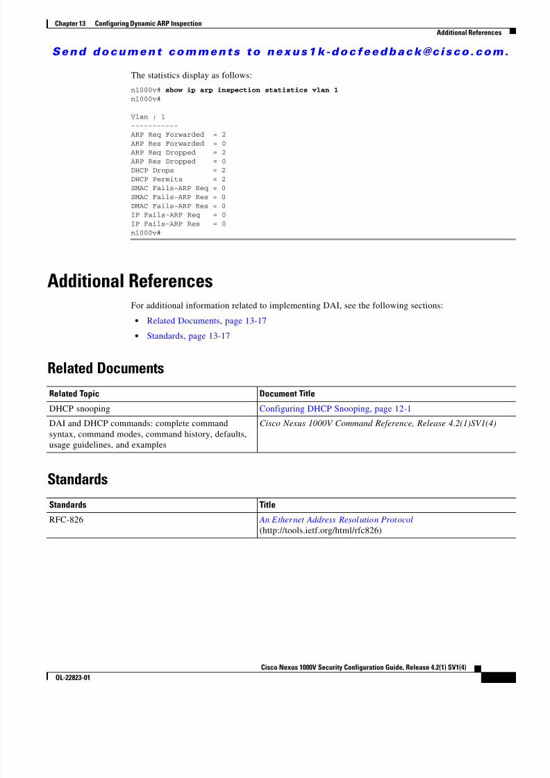
8/13/2019 n1000v Security
http://slidepdf.com/reader/full/n1000v-security 215/234
S e n d d o c u m e n t c o m m e n t s t o n e x u s 1 k - d o c f e e d b a c k @ c i s c o . c o m .
13-17Cisco Nexus 1000V Security Configuration Guide, Release 4.2(1) SV1(4)
OL-22823-01
Chapter 13 Configuring Dynamic ARP InspectionAdditional References
The statistics display as follows:
n1000v# show ip arp inspection statistics vlan 1n1000v#
Vlan : 1-----------
ARP Req Forwarded = 2ARP Res Forwarded = 0ARP Req Dropped = 2ARP Res Dropped = 0DHCP Drops = 2DHCP Permits = 2SMAC Fails-ARP Req = 0SMAC Fails-ARP Res = 0DMAC Fails-ARP Res = 0IP Fails-ARP Req = 0IP Fails-ARP Res = 0n1000v#
Additional ReferencesFor additional information related to implementing DAI, see the following sections:
• Related Documents, page 13-17
• Standards, page 13-17
Related Documents
Standards
Related Topic Document Title
DHCP snooping Configuring DHCP Snooping, page 12-1DAI and DHCP commands: complete commandsyntax, command modes, command history, defaults,usage guidelines, and examples
Cisco Nexus 1000V Command Reference, Release 4.2(1)SV1(4)
Standards Title
RFC-826 An Ethernet Address Resolution Protocol (http://tools.ietf.org/html/rfc826)

8/13/2019 n1000v Security
http://slidepdf.com/reader/full/n1000v-security 216/234
S e n d d o c u m e n t c o m m e n t s t o n e x u s 1 k - d o c f e e d b a c k @ c i s c o . c o m .
13-18Cisco Nexus 1000V Security Configuration Guide, Release 4.2(1) SV1(4)
OL-22823-01
Chapter 13 Configuring Dynamic ARP InspectionFeature History for DAI
Feature History for DAITable 13-2 lists the release history for the DAI feature.
Table 13-2 Feature History for DAI
Feature Name Releases Feature Information
DAI 4.0(4)SV1(2) This feature was introduced.

8/13/2019 n1000v Security
http://slidepdf.com/reader/full/n1000v-security 217/234
C H A P T E R
S e n d d o c u m e n t c o m m e n t s t o n e x u s 1 k - d o c f e e d b a c k @ c i s c o . c o m .
14-1Cisco Nexus 1000V Security Configuration Guide, Release 4.2(1) SV1(4)
OL-22823-01
14Configuring IP Source Guard
This chapter describes how to configure IP Source Guard on Cisco Nexus 1000Vs.
This chapter includes the following sections:
• Information About IP Source Guard, page 14-1
• Prerequisites for IP Source Guard, page 14-2
• Guidelines and Limitations, page 14-2
• Default Settings, page 14-2
• Configuring IP Source Guard, page 14-2
• Verifying the IP Source Guard Configuration, page 14-5
• Displaying IP Source Guard Bindings, page 14-5
• Example Configuration for IP Source Guard, page 14-5
• Additional References, page 14-5
• Feature History for IP Source Guard, page 14-6
Information About IP Source GuardIP Source Guard is a per-interface traffic filter that permits IP traffic only when the IP address and MACaddress of each packet matches the IP and MAC address bindings of dynamic or static IP source entriesin the Dynamic Host Configuration Protocol (DHCP) snooping binding table.
You can enable IP Source Guard on Layer 2 interfaces that are not trusted by DHCP snooping. IP SourceGuard supports interfaces that are configured to operate in access mode and trunk mode. When youinitially enable IP Source Guard, all inbound IP traffic on the interface is blocked except for thefollowing:
• DHCP packets, which DHCP snooping inspects and then forwards or drops, depending upon the
results of inspecting the packet. • IP traffic from static IP source entries that you have configured in the Cisco Nexus 1000V.
The device permits the IP traffic when DHCP snooping adds a binding table entry for the IP address andMAC address of an IP packet or when you have configured a static IP source entry.
The device drops IP packets when the IP address and MAC address of the packet do not have a bindingtable entry or a static IP source entry. For example, assume that the show ip dhcp snooping binding command displays the following binding table entry:

8/13/2019 n1000v Security
http://slidepdf.com/reader/full/n1000v-security 218/234

8/13/2019 n1000v Security
http://slidepdf.com/reader/full/n1000v-security 219/234

8/13/2019 n1000v Security
http://slidepdf.com/reader/full/n1000v-security 220/234
S e n d d o c u m e n t c o m m e n t s t o n e x u s 1 k - d o c f e e d b a c k @ c i s c o . c o m .
14-4Cisco Nexus 1000V Security Configuration Guide, Release 4.2(1) SV1(4)
OL-22823-01
Chapter 14 Configuring IP Source GuardConfiguring IP Source Guard
Adding or Removing a Static IP Source EntryUse this procedure to add or remove a static IP source entry on a device.
BEFORE YOU BEGIN
Before beginning this procedure, you must know or do the following:
• By default, there are no static IP source entries on a device.
SUMMARY STEPS
1. config t
2. [no ] ip source binding IP-address MAC-address vlan vlan-ID interface vethernetinterface-number
3. show ip dhcp snooping binding [interface vethernet interface-number ]
4. copy running-config startup-config
DETAILED STEPS
Step 5 copy running-config startup-config
Example:switch(config-if)# copy running-configstartup-config
(Optional) Copies the running configuration to thestartup configuration.
Command Purpose
Command Purpose
Step 1 config t
Example:switch# config tswitch(config)#
Enters global configuration mode.
Step 2 [ no ] ip source binding IP-address MAC-address vlan vlan-ID interface
vethernet interface-number
Example:switch(config)# ip source binding10.5.22.17 001f.28bd.0013 vlan 100 interface ethernet 3
Creates a static IP source entry for the currentinterface, or if you use the no option, removes astatic IP source entry.
Step 3 show ip dhcp snooping binding [ interface
vethernet interface-number ]
Example:switch(config)# show ip dhcp snoopingbinding interface ethernet 3
(Optional) Displays IP-MAC address bindings forthe interface specified, including static IP sourceentries. Static entries appear with the term “static” inthe Type column.
Step 4 copy running-config startup-config
Example:switch(config)# copy running-configstartup-config
(Optional) Copies the running configuration to thestartup configuration.
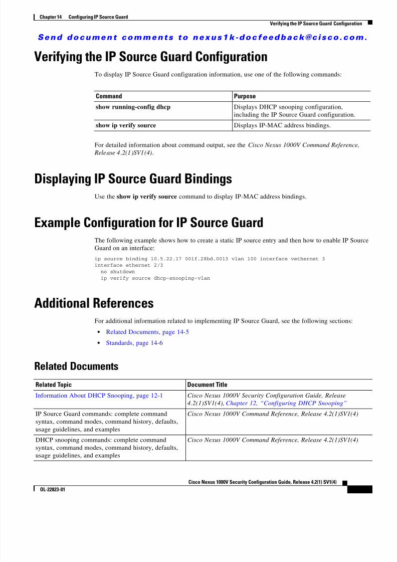
8/13/2019 n1000v Security
http://slidepdf.com/reader/full/n1000v-security 221/234
S e n d d o c u m e n t c o m m e n t s t o n e x u s 1 k - d o c f e e d b a c k @ c i s c o . c o m .
14-5Cisco Nexus 1000V Security Configuration Guide, Release 4.2(1) SV1(4)
OL-22823-01
Chapter 14 Configuring IP Source GuardVerifying the IP Source Guard Configuration
Verifying the IP Source Guard ConfigurationTo display IP Source Guard configuration information, use one of the following commands:
For detailed information about command output, see the Cisco Nexus 1000V Command Reference, Release 4.2(1)SV1(4) .
Displaying IP Source Guard BindingsUse the show ip verify source command to display IP-MAC address bindings.
Example Configuration for IP Source GuardThe following example shows how to create a static IP source entry and then how to enable IP SourceGuard on an interface:
ip source binding 10.5.22.17 001f.28bd.0013 vlan 100 interface vethernet 3interface ethernet 2/3 no shutdown ip verify source dhcp-snooping-vlan
Additional ReferencesFor additional information related to implementing IP Source Guard, see the following sections:
• Related Documents, page 14-5
• Standards, page 14-6
Related Documents
Command Purposeshow running-config dhcp Displays DHCP snooping configuration,
including the IP Source Guard configuration.
show ip verify source Displays IP-MAC address bindings.
Related Topic Document Title
Information About DHCP Snooping, page 12-1 Cisco Nexus 1000V Security Configuration Guide, Release4.2(1)SV1(4), Chapter 12, “Configuring DHCP Snooping”
IP Source Guard commands: complete commandsyntax, command modes, command history, defaults,usage guidelines, and examples
Cisco Nexus 1000V Command Reference, Release 4.2(1)SV1(4)
DHCP snooping commands: complete commandsyntax, command modes, command history, defaults,usage guidelines, and examples
Cisco Nexus 1000V Command Reference, Release 4.2(1)SV1(4)

8/13/2019 n1000v Security
http://slidepdf.com/reader/full/n1000v-security 222/234
S e n d d o c u m e n t c o m m e n t s t o n e x u s 1 k - d o c f e e d b a c k @ c i s c o . c o m .
14-6Cisco Nexus 1000V Security Configuration Guide, Release 4.2(1) SV1(4)
OL-22823-01
Chapter 14 Configuring IP Source GuardFeature History for IP Source Guard
Standards
Feature History for IP Source GuardTable 14-2 lists the release history for this feature.
Standards Title
No new or modified standards are supported by thisfeature, and support for existing standards has not beenmodified by this feature.
—
Table 14-2 Feature History for IP Source Guard
Feature Name Releases Feature Information
IP Source Guard 4.0(4)SV1(2) This feature was introduced.

8/13/2019 n1000v Security
http://slidepdf.com/reader/full/n1000v-security 223/234
C H A P T E R
S e n d d o c u m e n t c o m m e n t s t o n e x u s 1 k - d o c f e e d b a c k @ c i s c o . c o m .
15-1Cisco Nexus 1000V Security Configuration Guide, Release 4.2(1) SV1(4)
OL-22823-01
15Disabling HTTP Server
This chapter describes how to disable the HTTP server and includes the following topics:
• Information About the HTTP Server, page 15-1
• Guidelines and Limitations, page 15-1
• Default Setting, page 15-2
• Disabling HTTP Server, page 15-2
• Verifying the HTTP Configuration, page 15-3
• Additional References, page 15-3
• Feature History for Disabling the HTTP Server, page 15-4
Information About the HTTP ServerAn HTTP server, which can be turned off from the CLI to address security concerns, is embedded in theVirtual Supervisor Module (VSM).
If you want to turn off the HTTP server, see the following “Guidelines and Limitations” .
Guidelines and Limitations• The HTTP server is enabled by default.
• VUM will not install VEMs if the HTTP server is disabled. During VEM installation, VUM talksdirectly to the HTTP server to extract required module information from the VSM. To install VEMs,you must do one of the following: – Use VUM by enabling the HTTP server during VEM installation, and then disabling it after the
VEMs are installed. – Install VEMs manually without using VUM.
• The HTTP server must be enabled in order to get the Cisco Nexus 1000V XML plugin from theVSM.

8/13/2019 n1000v Security
http://slidepdf.com/reader/full/n1000v-security 224/234
S e n d d o c u m e n t c o m m e n t s t o n e x u s 1 k - d o c f e e d b a c k @ c i s c o . c o m .
15-2Cisco Nexus 1000V Security Configuration Guide, Release 4.2(1) SV1(4)
OL-22823-01
Chapter 15 Disabling HTTP ServerDefault Setting
Default SettingThe HTTP server is enabled by default.
Disabling HTTP ServerUse this procedure to disable the HTTP server.
BEFORE YOU BEGIN
Before beginning this procedure, you must know or do the following:
• You are logged in to the CLI in EXEC mode.
• By default, the HTTP server is enabled.
SUMMARY STEPS
1. config t
2. no feature http-server
3. show http-server
4. copy running-config startup-config
DETAILED STEPS
Command Purpose
Step 1 config t
Example:n1000v# config tn1000v(config)#
Enters CLI global configuration mode.
Step 2 no feature http-server
Example:n1000v(config)# no feature http-servern1000v(config)#
Disables the HTTP server.
Step 3 show http-server
Example:n1000v(config)# show http-serverhttp-server disabled
(Optional) Displays the HTTP serverconfiguration (enabled or disabled).
Step 4 copy running-config startup-config
Example:n1000v(config)# copy running-configstartup-config[########################################]100%n1000v(config)#
(Optional) Saves the running configurationpersistently through reboots and restarts bycopying it to the startup configuration.

8/13/2019 n1000v Security
http://slidepdf.com/reader/full/n1000v-security 225/234
S e n d d o c u m e n t c o m m e n t s t o n e x u s 1 k - d o c f e e d b a c k @ c i s c o . c o m .
15-3Cisco Nexus 1000V Security Configuration Guide, Release 4.2(1) SV1(4)
OL-22823-01
Chapter 15 Disabling HTTP ServerVerifying the HTTP Configuration
Example:config tno feature http-server
Verifying the HTTP ConfigurationTo display the HTTP configuration, use the following commands:
Example 15-1 show http-server
n1000v(config)# show http-serverhttp-server enabledn1000v(config)#
Example 15-2 show feature
n1000v(config)# show featureFeature Name Instance State-------------------- -------- --------dhcp-snooping 1 disabledhttp-server 1 disabledippool 1 disabledlacp 1 disablednetflow 1 disabledprivate-vlan 1 disabledsshServer 1 enabledtacacs 1 disabledtelnetServer 1 disabledn1000v(config)#
Additional ReferencesFor additional information related to implementing Telnet, see the following sections:
• Related Documents, page 15-4
• Standards, page 15-4
Command Purpose
show http-server Displays the HTTP server configuration.
See Example 15-1
show feature Displays the features available, such as LACP, andwhether they are enabled.
See Example 15-2

8/13/2019 n1000v Security
http://slidepdf.com/reader/full/n1000v-security 226/234
S e n d d o c u m e n t c o m m e n t s t o n e x u s 1 k - d o c f e e d b a c k @ c i s c o . c o m .
15-4Cisco Nexus 1000V Security Configuration Guide, Release 4.2(1) SV1(4)
OL-22823-01
Chapter 15 Disabling HTTP ServerFeature History for Disabling the HTTP Server
Related Documents
Standards
Feature History for Disabling the HTTP ServerThis section provides the release history for disabling the HTTP server.
Related Topic Document Title
Complete command syntax, commandmodes, command history, defaults,usage guidelines, and examples
Cisco Nexus 1000V Command Reference, Release 4.2(1)SV1(4)
Standards Title
No new or modified standards are supported by thisfeature, and support for existing standards has not beenmodified by this feature.
—
Feature Name Releases Feature Information
Disable HTTP server 4.2(1)SV1(4) This feature was introduced.

8/13/2019 n1000v Security
http://slidepdf.com/reader/full/n1000v-security 227/234
C H A P T E R
S e n d d o c u m e n t c o m m e n t s t o n e x u s 1 k - d o c f e e d b a c k @ c i s c o . c o m .
16-1Cisco Nexus 1000V Security Configuration Guide, Release 4.2(1) SV1(4)
OL-22823-01
16Security Configuration Limits
Table 16-1 shows the maximum configuration limits for Security features.
Table 16-1 Security Maximum Configuration Limits
Security Feature Maximum Limit
Active VLANs across all VEMs 2000
MAC addresses over VLAN within a VEM 32000
MAC addresses per VLAN within a VEM 4000
Secure vEths per VSM 2000
Secure MACs per VSM 8000
Secure MACs per vEth 1025
ACLs 128
ACEs per ACL 128
Per DVS Per Host
ACL Interfaces 2048 256
NetFlow Policies 32 8
NetFlow Interfaces 256 32
SPAN/ERSPAN Sessions 64 4
Port Security 2K 216
Multicast Groups 512 64
Virtual Service Domains (VSD) 64 6
VSD Interfaces 2048 214

8/13/2019 n1000v Security
http://slidepdf.com/reader/full/n1000v-security 228/234
S e n d d o c u m e n t c o m m e n t s t o n e x u s 1 k - d o c f e e d b a c k @ c i s c o . c o m .
16-2Cisco Nexus 1000V Security Configuration Guide, Release 4.2(1) SV1(4)
OL-22823-01
Chapter 16 Security Configuration Limits
8/13/2019 n1000v Security
http://slidepdf.com/reader/full/n1000v-security 229/234
S e n d d o c u m e n t c o m m e n t s t o n e x u s 1 k - d o c f e e d b a c k @ c i s c o . c o m .
IN-1Cisco Nexus 1000V Security Configuration Guide, Release 4.2(1) SV1(4)
OL-22823-01
I N D E X
A
AAA
default settings 4-4
description 4-1 to 4-4
example configuration 4-9
guidelines 4-4
limitations 4-4
monitoring TACACS+ servers 6-3
prerequisites 4-4
server groups description 4-4
services 4-1
standards 4-9
TACACS+ server groups 6-12
verifying configurations 4-8
aaa authentication command 4-6
AAA servers
FreeRADIUS VSA format 5-4
access control lists
order of application 9-2
See ACLs.
types of 9-2
accounting
default 4-4
description 4-3
ACLs
configuring in port profiles 9-12,10-8
ARP inspection
See dynamic ARP inspection
authentication
console default 4-4
description 4-2
method default 4-4
authentication, authorization, and accounting. See AAA
authorization, description 4-3
av pair 6-3
C
Cisco
vendor ID 5-3,6-3class-map limits 16-1
clear a Telnet session 8-4
configuration limits 16-1
console
authentication default 4-4
configure login authentication 4-6
D
defaults
user access 2-4
default settings
AAA 4-4
HTTP 15-2
SSH 7-3
TACACS+ 6-4
Telnet 3-3,8-2
detection, DAI error-disabled interface 13-12
DHCP binding database
See DHCP snooping binding database
DHCP feature
enabling 12-5
DHCP snooping
binding database
See DHCP snooping binding database

8/13/2019 n1000v Security
http://slidepdf.com/reader/full/n1000v-security 230/234

8/13/2019 n1000v Security
http://slidepdf.com/reader/full/n1000v-security 231/234
S e n d d o c u m e n t c o m m e n t s t o n e x u s 1 k - d o c f e e d b a c k @ c i s c o . c o m .
Index
IN-3Cisco Nexus 1000V Security Configuration Guide, Release 4.2(1) SV1(4)
OL-22823-01
interfaces, VSD 3-1
IP ACLs
changing an IP ACL 9-7
configuring 9-5 to ??
creating an IP ACL 9-6
default settings 9-5
description 9-1
guidelines 9-5,10-1
limitations 9-5,10-1
prerequisites 9-5
removing an IP ACL 9-9
verifying configuration 9-14
IP Source Guard
description 14-1
enabling 14-3
static IP source entries 14-4
L
limits, configuration 16-1
login AAA, about 4-1
login authentication
configuring console methods 4-6
M
MAC ACLs
changing a MAC ACL 10-3
creating a MAC ACL 10-2
description 10-1
removing a MAC ACL 10-5
mac port access-group command 9-13,10-9match criteria limit 16-1
O
option 82, DHCP snooping 12-15
P
password
checking strength 2-5,2-6
passwords
information about 2-3
policy map limits 16-1
port ACLs
applying 9-11,9-13
port-profile command 3-5
port profiles
ACL 9-12,10-8
port security
description 11-1enabling on an interface 11-6
MAC move 11-4
static MAC address 11-9
violations 11-4
preshared keys
TACACS+ 6-2
prohibited words 2-7
R
RADIUS
configuring servers 5-5 to 5-20
configuring the global key 5-7
configuring transmission retries 5-13
default settings 5-5
description 5-1 to 5-4
example configurations 5-22
network environments 5-1
operation 5-2
prerequisites 5-4
specifying server at login 5-10
verifying configuration 5-22
VSAs 5-3
RADIUS server groups
configuring 5-9

8/13/2019 n1000v Security
http://slidepdf.com/reader/full/n1000v-security 232/234
S e n d d o c u m e n t c o m m e n t s t o n e x u s 1 k - d o c f e e d b a c k @ c i s c o . c o m .
Index
IN-4Cisco Nexus 1000V Security Configuration Guide, Release 4.2(1) SV1(4)
OL-22823-01
RADIUS Servers
retries to a single server 5-15
RADIUS servers
configuring accounting attributes 5-16,5-17
configuring a timeout interval 5-14
configuring authentication attributes 5-16,5-17
configuring dead-time intervals 5-20
configuring hosts 5-6
configuring keys 5-8
configuring periodic monitoring 5-18
displaying statistics 5-22
example configurations 5-22
manually monitoring 5-21
monitoring 5-2
verifying configuration 5-22
recovery, DAI error-disabled interface 13-12
related documents 1-xvii, 1-xix
relay agent, DHCP snooping 12-15
remote session, Telnet IPv4 8-3
roles
example configuration 2-15
information about 2-1
interface access 2-12limitations 2-4
verifying 2-15
VLAN access 2-13
S
Secure Shell
default settings 7-3
security services, about 4-1server groups, description 4-4
service policy limits 16-1
service-port command 3-6
services, AAA, about 4-1
session, clearing Telnet 8-3,8-4
session, starting IPv4 Telnet 8-3
show HTTP server command 15-3
show Telnet server command 8-5
show virtual -service-domain command 3-8
SSH
default settings 7-3
generating server key-pairs 1-3,7-1
state enabled command 3-6,3-8
statistics
RADIUS servers 5-22
TACACS+ 6-22
switchport access vlan command 3-7
switchport mode trunk command 3-5
TTACACS+
configuring 6-5 to ??
configuring global timeout interval 6-16
configuring shared keys 6-9
default settings 6-4
description 6-1 to ??
disabling 6-8
displaying statistics 6-22
enabling 6-8example configurations 6-23
global preshared keys 6-2
guidelines 6-4
limitations 6-4
prerequisites 6-4
preshared key 6-2
specifying TACACS+ servers at login 6-15
user login operation 6-2
VSAs 6-3TACACS+ servers
configuration overview 6-6
configuring dead-time interval 6-21
configuring hosts 6-11
configuring periodic monitoring 6-20
configuring server groups 6-12
configuring TCP ports 6-18

8/13/2019 n1000v Security
http://slidepdf.com/reader/full/n1000v-security 233/234
S e n d d o c u m e n t c o m m e n t s t o n e x u s 1 k - d o c f e e d b a c k @ c i s c o . c o m .
Index
IN-5Cisco Nexus 1000V Security Configuration Guide, Release 4.2(1) SV1(4)
OL-22823-01
displaying statistics 6-22
monitoring 6-3
TCP ports
TACACS+ servers 6-18
Telnet 3-1,8-1
clearing a session 8-4
clear session 8-3
default setting 3-3,8-2
enable, disable 8-2
information about 8-1
prerequisites for 8-1
start IPv4 session 8-3
Telnet command 8-4
timeoutTACACS+ 6-16
U
user access
defaults 2-4
example configuration 2-15
verifying 2-15
user accountprohibited words 2-7
user accounts
configuring 2-6
guidelines 2-4
information about 2-1
limitations roles
guidelines 2-4
user names
information about 2-3user roles
creating 2-8
creating feature groups 2-10
V
vendor ID, Cisco 6-3
vendor-specific attributes (VSAs) 6-3
virtual service domain
create 3-8
display 3-8
interfaces 3-1
port profile
inside or outside 3-4
member 3-7
virtual -service-domain command 3-8
virtual-service-domain command 3-5
vmware port-group command 3-5VSAs
protocol options 5-3

8/13/2019 n1000v Security
http://slidepdf.com/reader/full/n1000v-security 234/234
S e n d d o c u m e n t c o m m e n t s t o n e x u s 1 k - d o c f e e d b a c k @ c i s c o . c o m .
Index