n6 mechanotechnics november 2016 - future managers
TRANSCRIPT
Copyright reserved Please turn over
T980(E)(N25)T
NOVEMBER EXAMINATION
NATIONAL CERTIFICATE
MECHANOTECHNICS N6
(8190236)
25 November 2016 (X-Paper) 09:00–12:00
This question paper consists of 7 pages and 1 formula sheet of 3 pages.
(8190236) -2- T980(E)(N25)T
Copyright reserved Please turn over
DEPARTMENT OF HIGHER EDUCATION AND TRAINING REPUBLIC OF SOUTH AFRICA
NATIONAL CERTIFICATE MECHANOTECHNICS N6
TIME: 3 HOURS MARKS: 100
INSTRUCTIONS AND INFORMATION 1. 2. 3. 4.
Answer ALL the questions. Read ALL the questions carefully. Number the answers according to the numbering system used in this question paper. Write neatly and legibly.

(8190236) -3- T980(E)(N25)T
Copyright reserved Please turn over
QUESTION 1 The rotor of an electric motor has a mass of 22,8 kg and a radius of gyration of 75 mm. The motor has a speed of 750 r/min and drives a machine by means of a single-plate friction clutch which transmits 145 N.m during engagement. The machine has an equivalent mass of 63,5 kg and a radius of gyration of 140 mm. The machine is at rest at the clutch engagement. The clutch plate has a mean diameter of 95 mm and a coefficient of friction of 0,3. Assume uniform wear. Calculate the following:
1.1 The axial force required to transmit the 145 N.m (3) 1.2 The power that the clutch can transmit at 750 r/min (2) 1.3 The combined speed after engagement (5) 1.4 The time of slippage (4) 1.5 The loss of energy during slippage (3) [17] QUESTION 2 2.1 A brake consists of a flexible band applied on the outside periphery of a brake
drum with a diameter of 750 mm to produce the braking action. One end of the band is subjected to a tension of 250 N and the other end is attached to a fixed pin. The angle of contact between the band and the brake drum is 230° and the coefficient of friction is 0,3. Calculate the maximum braking torque transmitted by the brake.
(4)
2.2 Calculate the maximum load which can be applied to the winding drum of a
crane if the following is given: The brake drum of 1,2 m diameter, attached to the winding drum, has an effective diameter of 420 mm. The contact angle of the brake drum is 230° and the coefficient of friction between the band and the drum is 0,35. The maximum allowable tension in the band is 5 kN.
(5)
[9]

(8190236) -4- T980(E)(N25)T
Copyright reserved Please turn over
QUESTION 3 3.1 The ram of a punching machine exerts an average force of 25 kN over a
distance of 28 mm. The mechanical efficiency of the machine is 75%. The flywheel rotates at 560 r/min before the punching stroke and at 240 r/min at the completion of the punching stroke. Calculate the moment of inertia of the flywheel.
(6)
3.2 Calculate the forces exerted on the front and rear wheels of a vehicle when all
four wheels are braked and on the point of skidding, if the vehicle has a mass of 1 400 kg. The wheel base is 3 m and the centre of gravity is 1,2 m behind the front wheels and 600 mm above the road surface. Assume a coefficient of friction between the wheels and road surface of 0,5.
(6)
[12] QUESTION 4 A bright steel shaft is supported at both ends by bearings 1,75 m apart. The shaft transmits 30 kW at 600 r/min. A pinion with a PCD of 85 mm rotates at 1 200 r/min, and drives a spur gear mounted on the shaft at 500 mm from the right-hand bearing. The normal pressure between these two gears is horizontal. A pulley for a flat, vertical belt drive has a mass of 80 kg and a diameter of 750 mm, and is mounted 500 mm from the left-hand bearing. The pulley drives a machine situated above the shaft. The angle of contact between the belt and the pulley is 180° and the coefficient of friction is 0,3. Calculate the following:
4.1 The torque transmitted by the shaft (1) 4.2 The torque transmitted by the pinion (1) 4.3 The tangential force between the gears (2) 4.4 The normal force between the gears (2) 4.5 The belt tensions T1 and T2 (5) 4.6 The reactions at the bearings in the vertical plane (6) [17]
(8190236) -5- T980(E)(N25)T
Copyright reserved Please turn over
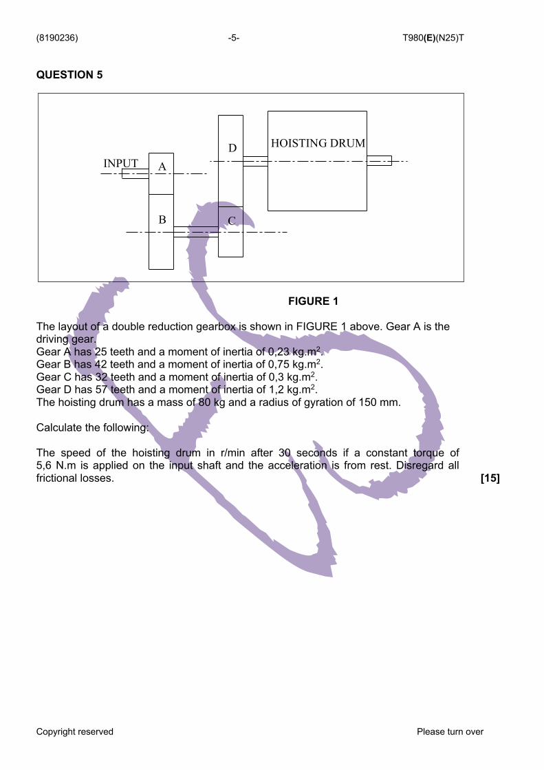
QUESTION 5
FIGURE 1
The layout of a double reduction gearbox is shown in FIGURE 1 above. Gear A is the driving gear. Gear A has 25 teeth and a moment of inertia of 0,23 kg.m2. Gear B has 42 teeth and a moment of inertia of 0,75 kg.m2. Gear C has 32 teeth and a moment of inertia of 0,3 kg.m2. Gear D has 57 teeth and a moment of inertia of 1,2 kg.m2. The hoisting drum has a mass of 80 kg and a radius of gyration of 150 mm. Calculate the following:
The speed of the hoisting drum in r/min after 30 seconds if a constant torque of 5,6 N.m is applied on the input shaft and the acceleration is from rest. Disregard all frictional losses.
[15]
INPUT A
B C
D HOISTING DRUM

(8190236) -6- T980(E)(N25)T
Copyright reserved Please turn over
QUESTION 6
FIGURE 2
In FIGURE 2 above, the four masses A, B, C and D are carried on a rotating shaft. Masses A, C and D are 10 kg, 6 kg and 5 kg respectively. The axial distances between the masses are as indicated. The mass centres are at 150 mm, 125 mm, 100 mm and 180 mm respectively from the axes of rotation. Use plane B as reference plane.
6.1 Compile the required table, using the given data and draw the coupler
diagram to scale: 50 mm = 0,1 kg.m2.
(6) 6.2 Draw the force diagram to scale: 50 mm = 0,1 kg.m. (5) 6.3 Calculate the minimum value of mass B. (3) 6.4 Determine the relative positions of masses B and C with respect to A, to
ensure complete dynamic balance.
(4) [18]
500 mm 500 mm 500 mm
A B C D
150 125 100 180

(8190236) -7- T980(E)(N25)T
Copyright reserved Please turn over
QUESTION 7
FIGURE 3 FIGURE 3 above shows the instantaneous configuration of a slider crank mechanism. The crank AB rotates at 210 r/min about the fixed centre A. Slide block C reciprocates horizontally and slide block E reciprocates vertically. The slide block E is driven by link DE which is attached to centre D on the connecting rod BC. AB = 100 mm; BC = 210 mm; DE = 180 mm
7.1 Draw the velocity diagram for the position shown. (6) 7.2 Determine the following: 7.2.1 The velocity of slider C 7.2.2 The velocity of slider E 7.2.3 The centripetal acceleration of B relative to A
(3 × 2) (6) [12]
TOTAL: 100

(8190236) -8- T980(E)(N25)T
Copyright reserved Please turn over
MECHANOTECHNICS N6 FORMULASHEET
1.
3.
5.
7.
9.
2. DO = m × (T + 2)
4.
6.
8. NA × TA = NB × TB 10. Fr = Ft × Tan
11. Fn = Ft × Sec 12. Ie = IA + (VR)2 IB + (VR)2 IC + (VR)2 ID 13. T" = Ie × "A
15.
17.
19. TA = TS + 2TP 21. v = p × (d + t) × N
23.
25. Tc = m × v2
14.
16. 18. Ti + To + Th = 0
20.
22. P = Te × v 24. T1 = * × A
26.
27.
28. Tg = m × g × sin 29. v = T × r
TPCDm =
)TBTA(mC +´=2
TBTAVR =
NANBVR =
PCDTFt ´
=2
221 mvKe =
pinion of PCDgear ofPCDVR =
f
f
IBIA
AB
AB
NANB
===aa
ww
nPCDP ´
=p
µqeTT
=21
211 hhha TD
)NA()ND(TBC
)NA()NB(TAT ++=
ηGRTT INPUTOUTPUT ´´=
gearsdrivingonTeethgearsdrivenonTeeth
speedOutputspeedInput
=
aµqcoseceTCTTCT
=--21
( ) ( ) CCdDdDL 2
42
2+
´±
++´=p
f
-1-
(8190236) -9- T980(E)(N25)T
Copyright reserved Please turn over
30.
32.
34.
36.
38. T1 = w × n × ft
40.
42. T = F × r 44. do = de + 0,65P
31.
33.
35.
37. m = w × t × L × D 39. P = Pg + Pµ
41.
43. w = do + 3d - 1,5155P
45.
46.
47.
48.
50.
52.
54. 56. L = 2C + pD
58. One load =
49.
51.
53.
55. Vol. bucket =
57. Self-weight =
59. T (acc load) = (T1 - T2)R
rgv ´´= µ
úû
ùêë
é-+
=qµqµ
TanTangrv
1
n
TanTan
TT
úû
ùêë
é-+
=qµqµ
11
21
CrRCos +
=2f
TIt w´
=
hrbgv
´´´
=2
úû
ùêë
é-
+=
qqtan/bh/bhTangrv
22
CrRCos -
=2q
60TNP ´´´
=p2
)(cosmw qp 22´
=
( )úûù
êëé -= qqp Cossinmh
41
22221
211 22
gh)v(Rhopgh)v(
Rhop
++=++
ygx)Va(Vw2
2=
dgvfhf
´´´´´
=2
4 2!
)aA(
)gh(aACdQ
22
2
-
´´´=
)CosRg(V q´´=
hSgm
´´´
42
miCv =
5
2
d3,026Ofhf´
´´=
!
)m(
)gh(ACdQ
1
22 -
´´=
vsm
´´
r
hSgm
´´´
81 2
-2-
(8190236) -10- T980(E)(N25)T
Copyright reserved Please turn over
60. T (acc drum) =
61. P = T × T
63.
65. P = Ke × operations/sec 67. µ = Tan 69. T = µ × F × Re × n 71. T = µ × n × (Fc - S)R
73.
62. T = 2p × N
64.
66. (I1 + I2)T3 = I1T1 + I2T2
68.
70.
72. Fc = m × T 2 ×
74. Tractive effort = mass on driving wheels × µ × g 75. Side thrust = FcCos
76.
77.
RamkI ´=´ 2a
221 w´= IKe
q
g=
2mvFc
efficiencydoneworkKe =
)(TanTan
fqqh+
=
qµsin
ReFT ´´=
g
qq Sinmg-
qqqqµ
SinFcCosmgSinmgCosFc
+-
=
mghCmgLPl +=
-3-