n89-10068 - nasa · by an expert with time-saving graphic manipulation tools. ... ai techniques....
TRANSCRIPT

N89-10068/,i. ._ 5
PLAN-IT: SCHEDULING ASSISTANT FOR SOLAR SYSTEM
EXPLORATION
William C. Dias
ITT Federal Electric Corp.
Julia A. Henricks
Jet Propulsion Laboratory
California Institute of Technology
Jennifer C. Wong
Jet Propulsion Laboratory
California Institute of Technology
! )X '
ABSTRACT
At the Jet Propulsion Laboratory (JPL), the scheduling of spacecraft
activities is a complex endeavor for which streamlining is always
being sought. Using the Comet Rendezvous Asteroid Flyby mission (CRAF
- proposed for 1993 launch) as a development base, PLAN-IT (a frame-
based expert scheduling system shell) has been adapted to assist in
one phase of schedule generation. PLAN-IT CRAF automatic scheduling
routines attempt to return a 'good-cut' schedule which can be adjusted
by an expert with time-saving graphic manipulation tools. Work todate has led to a "GO" decision on technical factors for online
capability development.
INTRODUCTION
The scheduling of spacecraft activities at the Jet Propulsion
Laboratory (JPL) is a very involved process requiring many personnel
over long time periods (1,2). The use of specialized automation tools
has evolved and been encouraged over the years to increase the
effectiveness and responsiveness to changes in the scheduling
processes (3). Although the use of automation in the scheduling
process reduces the workload of scheduling personnel, a main benefit
is to gather more science data by allowing the scheduling of as many
activities as possible while controlling mission risk.
Recent interest has increasingly focused on the potential of
artificial intelligence (AI) to achieve those ends (4). Future
spacecraft schedules will have a greater need for advanced schedulingautomation tools because of enhanced spacecraft capabilities and the
desire to automate tasks which are now labor intensive.
The scheduling of spacecraft activities may be divided into five
phases (5):
I) Request Generation
2) Request Integration
3) Activity Detail Design
Collection and preprocessing of
requirements
Integration of requests into a
timeline
Refinement of detail in schedule
https://ntrs.nasa.gov/search.jsp?R=19890000697 2018-07-30T04:07:24+00:00Z

4) SequenceGeneration
5) CommandGeneration
Translation of plan to a sequenceof commandsTranslation of commands to
program load
A scheduling program called PLAN-IT, short for Plan-Integrated
Timelines, provides general interactive scheduling capabilities using
AI techniques. It has proved to be applicable to spacecraft
scheduling in the Request Integration Phase. The test case for the
study of this applicability was the Comet Rendezvous Asteroid Flyby
(CRAF) mission and is the subject of this paper.
BASIC, STRUCTURED, AND EXPERT
SCHEDULING TECHNIQUES
Recent literature has pointed out advantages to "evolutionarydelivery" or other staged delivery of complex, innovative software
systems (6,7). This paper takes the view that construction of an
Expert System for scheduling benefits by this treatment. A scheme for
evolution of expert functionality is outlined in this section.
The art of scheduling encompasses many techniques and methods for
generating a "good" schedule. Schedulers' techniques fall into three
categories: Basic, Structured and Expert. One approach to development
of an Expert System for a given scheduling application is to evolve
from a simple to a more complex level of support. This can be done by
increasing the level of intelligence being represented in the system,
progressing from the Basic through the Structured and finally the
Expert categories of support as outlined below. Attempts to develop
Expert Systems from manual systems or those automated at only a Basic
support level may incur excessive and unnecessary development risk.
An Expert System should encompasses not only the Expert techniques,but also the Basic and Structured techniques as described below.
Basic
The Basic category of scheduling techniques emphasizes manual control
of basic operations performed on individual activities. Basic
techniques focus on a single activity and not on how this activityaffects other activities. Knowledg_ of how a decision affects the
schedule may be represented in the system and displayed graphically.That knowledge does not o_tz_l execution of a command at the basic
level, but may be used to report information to the operator. Usingthis knowledge, the operator controls execution. One of the effects
of this is allowing systems to be partially functional in real
environments with less completeness in the system internal knowledge.
The Basic category encompasses three functional operations: move an
activity to another time frame, delete an activity, and add newactivities to the schedule.
This category emphasizes manual execution which gives the user the
flexibility to move activities at his discretion. The user scans the
schedule and manually moves an activity to an area of lesser conflict.
The strength of these techniques is best illustrated where it is
desired to alter a schedule which has already been generated.
2

These Basic techniques are widely used in scheduling. Systems which
address this category of techniques can be applied in a wide variety
of scheduling situations. An expert scheduling system 'shell' should
include these basic operations.
The Structured category incorporates more knowledge of the attributes
of an activity. System internal knowledge controls execution of
functions to a greater degree than with the Basic category. Examples
of knowledge attributes include separation criteria or precedence
relations among activities. The Structured category also operates
coherently on groups of activities or combines the effects of several
basic techniques.
The following examples of structured operations show why more
knowledge about activities must be present in the system for correct
execution:
lo
2.
3.
4.
5.
Move activity A after activity B.
Adjust separation times between activities of typeC to a maximum of 20 minutes and a minimum of 5 minutes.
Insert activity D between activities E and F,
and shorten its duration accordingly.
Repeat activity G at the same time, every
day of the week.
Reschedule activity H at time Z, and automatically
reschedule activities logically dependent on activity H
accordingly.
It can be seen that operations in the Structured category are more
specific than those in the Basic category. There may be a subset of
operations which are applicable to broad generic classes of
scheduling. For instance, Operation 5 could be included in a generic
scheduling tool devoted to handling problems with inter-activity
temporal dependencies such as on a Pert Chart. The operations in the
Structured category are usually very specific for a particular
application.
The Expert category is characterized by operations which:
a)
b)
c)
Encompass many activitiesInclude heuristics or 'rules of thumb' for simplifying
scheduling problems
Generate "good" schedules by complex rules, such as:
i. Rearranging the schedule to minimize total conflict.
2. Rearranging the schedule to minimize the variance in
work loads over time.
3. Delete activities, as necessary until conflicts are
eliminated.
There is no hard and fast division between Structured category
techniques and Expert category techniques. Evolution from the
Structured category to the Expert category is a low-risk means of

evolving towards an Expert System for a specific schedulingapplication.
PLAN-IT OVERVIEW
This section provides an overview description of PLAN-IT, the toolused to develop the scheduler for the CRAFtest case. The term"developers" used in this context refers to the people customizingPLAN-IT for a particular application. The term "user" refers to theperson who will use the customized version of PLAN-IT to generateschedules.
PLAN-IT is an interactive scheduling tool. PLAN-IT is written inZetalisp on a Symbolics 3640 using version 6.1 of the operatingsystem. PLAN-IT utilizes the frame features and object orientedprogramming capability provided by the Zetalisp FLAVORsystem. TheSymbolics has a high-resolution graphic screen and a three key mousewhich is utilized by PLAN-IT to enhancethe user interface.
The PLAN-IT screen (see Figure I) graphically displays the activities
which are scheduled and the resources the activities utilize. The
PLAN-IT screen graphically represents the methods experts use to lay
out a schedule. The upper portion of the PLAN-IT screen displays
activities as a series of horizontal lines. Resources are represented
as horizontal rectangles (thick rectangular bars) directly below theactivity area. A white area in the resource line indicates that a
resource is not allocated; gray implies utilization within the bounds
of a given maximum; black indicates an interval of oversubscription orconflict.
Activities are internally represented with frames (8,9). Resources
are internally represented as blackboards (8,10). Each resource line
maintains internal lists of conflict and usage ratings for each
interval of time. These interval bounds are determined as the point
where usage differs. Any change (permanent or provisional) to an
activity forces maintenance of the associated blackboards with an
optional screen update.
PLAN-IT 'strategies' are blocks of code which, when invoked, assist
the user in resolving or analyzing conflicts. These strategies areinitiated from a pop-up menu.
Developers customizing PLAN-IT to a given application must have
knowledge of PLAN-IT's internal functions and a background in
Zetalisp. Software to interpret the input file and to display the
desired output to the end user must be generated for each unique
application. Each resource timeline is defined by utilizing a series
of macros developed specifically by the original PLAN-IT designers.Code which defines and displays conflict on the resource blackboards
must be written, again with help of PLAN-IT macros. The next step is
the design and implementation of software strategies to assist the
user in generating a "good" schedule. Since PLAN-IT is an ongoingdevelopment, changes to the core code (i.e., below the level of the
macros), may be required in a specific application when conditions arenot fully representable in the macros.
4

m
m_wm-iP_
_qP-_m_7
uqp-w
H
wnl
IXGI Tpl.-llpt--pl_mm_l
lu_-_umml
_l/vwl.-mwl-e,_
&Jllm-nl_lKT
IIIIII
rll
I
I
I
I I
M
_w
I
FIGURE 1
Top screen shows a single track as initially loaded by PLAN-IT.
shows the same track after the conflicts have been removed.
. • • • i_:=_._=:.;;, . • : . , - _ . o . o _ o _r. " I
PLAN-IT SCREEN Conflicts are indicated by the solid-black bars.Bottom screen
5

CRAF PROBLEM OVERVIEW
The CRAF mission has a proposed launch date of 1993 (II). After a
cruise of several years with several gravitational assists from close
flyby of planetary bodies and an asteroid encounter, CRAF will
encounter the comet Tempel 2 near the orbit of Jupiter in 1996. After
conducting preliminary science activities, CRAF will accompany the
comet past perihelion (closest approach to the sun) in 1999. The
early encounter phase is expected to have power resource constraints
due to the combined effects of spacecraft dependency on solar power
while distant from the sun, battery storage, and a small nuclear powersource.
The spacecraft instruments are housed on two separately movable scan
platforms, on a stationary boom, and on the spacecraft body. The
instruments on platforms are fixed to those platforms, thus it is the
platform that is slewed to achieve the proper orientation for a
requested observation, not the instrument itself. These instruments
collect science, engineering and navigational data. This data is
collected at specific data rates which must either be recorded on tape
or communicated to the ground via antennas in the Deep Space Network(DSN).
Our test set consisted of nine hypothetical requests for science,
navigation and engineering activities over a one week period near
Tempel 2 perihelion. Each request represented multiple occurences of
an activity, so the nine requests expanded to 77 activities. The
activities had requirements and constraints on instrument usage, the
platform pointing position, spacecraft orientation, data rate, and
separation time. One request required use of the digital tape recorder
(DTR) for record and playback. Ground rules for this demonstration
stipulated that all activities were to be performed during the nine
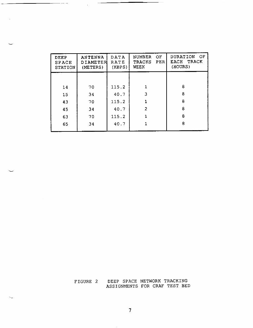
hypothetical CRAF DSN tracking viewperiods (See Figure 2). The data
rate constraints in those tracks place limitations on the DSN link
capabilities and tape playback speeds.
From the nine requests, the developers extracted the details impliedby the requests and derived the definitions for conflict and
constraint violation conditions. The following is a description ofthe extracted details.
First, of the nine requests, two were multi-phase. These two multi-
phase requests were expanded into five single-plase requests for a
total of twelve requests. A description of the twelve requests and
their attributes are found in Figure 3.
Second, requests fell into two categories: short- and long-duration.
The short-duration activities were performed one or more times per
week. These short-duration activities had a higher priority than
activities which were requested continuously throughout the one-weekperiod.
In contrast, the long-duration activities were requested to be
continuous. Portions of these activities could be suspended in favorof the short-duration activities.
DEEP
SPACE
STATION
14
15
43
45
63
65
ANTENNA
DIAMETER
(METERS)
70
34
70
34
70
34
DATA
RATE
(KBPS)
115.2
40.7
115.2
40.7
115.2
40.7
NUMBER OF
TRACKS PER
WEEK
1
3
1
2
1
1
DURATION OF
EACH TRACK
(HOURS)
8
8
8
8
8
8
_vr
FIGURE 2 DEEP SPACE NETWORK TRACKING
ASSIGNMENTS FOR CRAF TEST BED
7

ACTIVITY
VTARCAL-RT
VTARCAL-RCD
VTARCAL-PB
MAGROL
NOPNAV
DCOUNT
VJETA
MCHAR-C
MCHAR-A
MCHAR-L
WLOW
WHIGH
DEFINITIONS:
(I)
(2)
[NSTRUMEN_
ISS
ISS
MAG
ISS
DC
ISS
NMS
NMS
NMS
PWA
PWA
PLATFORM
HPSP
HPSP
HPSP
LPSP
HPSP
LPSP
LPSP
LPSP
MANEUVER
STAT
MNVR
STAT
MNVR
STAT
STAT
STAT
STAT
STAT
STAT
D-C
D-C
TARGET
STAR-FIELD
CAL-PLATE
STAR/COMET
COMET
COMET-JET
COMET
ANTI-COMET
COMET
DATA-RATE
(BPS)
)URATION
(MIN)
I15.2K 60
115.2K 120
100.SK 170
400 45
I15.2K i0
44 cont
I15.2K 20
I000 60
i000 60
300 cont
200 cont
I15.2K I0
PERFORMANCE
CONSTRAINTS
once
once
after VTARCAL
once
once/track
(I)
twice/track{2)
once�track
once
once/track
Cont
DC
D-C
HPSP
ISS
LPSP
MAG
MNVR
NMS
P WA
STAT
Continuous
Dust Counter
Don't Care, doesn't matter if spacecraft is maneuvering or stationary
High Precision Scan Plat forme
Imaqlng Subsystem (cameras)
Low Precision Scan Platform
Magnetometer
Spacecraft required to manuever
Neutral Mass Spectrometer
Plasma Wave Analyzer
Spacecraft required to be stationary
LPSP pointed at the comet 50% of time as well as
at least once every two hours for i0 minutes
Occurences within each track to be separated by at least
5 hours but not more than 7 hours
v
FIGURE 3 CRAF TEST BED ACTIVITY REQUIREMENTS
8

Third, from the twelve requests, definitions for conflict and
constraint violation conditions were derived. Conflicts occurred when
activities were scheduled in a time frame which required more
resources than were available.
An example of an instrument usage conflict is two activities requiring
the same instrument to be scheduled at the same time. An instrument
can only accomodate one activity at a time.
An example of a constraint violation can occur with respect to
spacecraft movement. An activity requiring the spacecraft to be
stationary during its observation cannot be scheduled in the same time
frame as an activity requiring the spacecraft to be maneuvered. A
more detailed description of conflict and constraint definitions is
included in the next section.
PLAN-IT CUSTOMIZATION FOR CRAF
This section discusses the CRAF test case with respect to PLAN-IT.
The representations of the various data elements such as activities,
resources, conflicts and constraints are discussed below. The
different scheduling technique categories (Basic, Structured, Expert)
added to the PLAN-IT repertoire, and the rationale for selecting these
techniques are reviewed.
Personnel Backaround
Three engineers developed the PLAN-IT overlay code for the CRAF test
case over a time span of seven months. The seven month implementation
period included: i) gaining experience in LISP programming, 2)
familiarization with the PLAN-IT core code, 3) defining the CRAF-
specific representation and processing requirements, and 4) coding of
those requirements. The engineers combined work experience included
spacecraft scheduling and programming for resource allocation
problems. The original PLAN-IT designers were available for
consultation throughout the seven months, as were CRAF spacecraft
engineers. Development efforts culminated in a PLAN-IT CRAF proof-of-
concept demonstration in October 1986, followed by informal CRAF
project recognition of the product's overall potential.
Activity Representation
Activities were represented as frames with slots for each specific
attribute of the activity. The attributes were a unique identifier,
the start/stop times, the duration of the activity, maneuver status,
platform targetting, data rate, and time windows. PLAN-IT created the
activity frames as it parsed the input request data file.
_esource Conflict Representation
Resources were internally represented as blackboards. Each resource
timeline contained time intervals, conflict and usage ratings. As
activities were moved within the schedule, the resource blackboards
updated themselves accordingly. Following is a description of each
resource utilized by the CRAF activities and a description of the
9

conflict and constraint conditions that were applicable to eachresource.
Instrument usage was represented on the INST_X_m_T USAGE lines (PWA,
ISS, DCS, MAG, NMS resource lines in Figure i). A unique resourceline was assigned to each of the five instruments. The conflict
representation associated with each of the instrument resource
timelines was correspondingly simple - a single instrument usage could
be requested by only one activity within any time frame. Graphically
the resource timelines displayed white when the instrument is not
used, gray when the instrument was requested for usage by one
activity, and black when several activities requested the same
instrument in the same time frame. Dedicated instrument use was
assumed to be required for all CRAF activities, although in practice,
scientists occasionally use the same data for multiple experiments.
The data rate resource was represented on the DATA RATE line. Each
DSN antenna is characterized with the ability to support a spacecraft
track within its maximum data rate capacity which is determined by
equipment configuration and distance to the spacecraft. Figure 2
shows the data rate capacity for each test DSN track. All activities
were scheduled within the given data rate envelopes. The DSN antennas
can support several activities in the same time interval provided the
sum of the activities' data rates does not exceed the maximum DSN link
capacity. The DATA RATE resource line showed white when no data
activity took place, gray when some bandwidth was used, and black whenthe maximum data rate was exceeded.
Targetted usage of instruments on the Low Precision Scan Platform
(LPSP) was represented on the LPSP TARGZT line. These instruments
had very general targetting criteria. General targets were symbolizedby the target name, for example, EARTH, STAR and COMET. Activities
were in conflict when they disagreed on general pointing requirements.
The LPSP TARGET resource line showed gray when an instrument on the
low precision scan platform had targetting requirements. Thus, the
resource line showed white when none of the LPSP instruments was used
or if an LPSP instrument was in use but untargetted. Black showed when
conflicting targets were requested for the same time.
Usage of instruments on the High Precision Scan Platform (HPSP) was
represented on the BPSP TARGET line. In contrast to the LPSP, the
HPSP instruments (i.e., the cameras) had such exact targettingcriteria that no two independently requested activities could
conjointly utilize the same platform orientation. Representing exact
targetting criteria (azimuth and elevation angles) would require a
significant coding effort beyond the coding assistance provided by thePLAN-IT macros.
For the above reasons, the HPSP TARGET line showed a conflict
whenever the high precision scan platform supported two different
activities concurrently, regardless of how they were targetted. In
this data set, the result was somewhat trivialized by the fact that
only one instrument was present on the HPSP, unlike the actual plan
for CRAF which has a complement of scientific and engineeringinstruments on the HPSP.
I0

Maneuver status was represented on the MANEUVER resource line.
Activities had one of the following maneuver states: YES maneuver the
spacecraft, NO don't maneuver the spacecraft or DON'T CARE whether the
spacecraft is manuevered or stationary. The assumptions made were:
(a) No two activities which required the spacecraft to
maneuver could share the same maneuver
(b) No activity which required the spacecraft to be stationary
could coexist with an activity whichmaneuvered,
though several stationary activities could co-exist with
each other
(c) Activities which don't care about maneuvering
could coexist with any other activity.
Maneuver conflict code was written which stated that if two activities
of the type (a) or (b) occurred, a conflict was displayed on theMANEUVER resource line. Portions of the maneuver resource line showed
gray if one or more activities requiring a stationary spacecraft were
concurrent, or if a single activity requiring a maneuver was
scheduled. Any activity with LPSP or HPSP targetting requirements
required, by default, a stationary spacecraft unless a maneuver was
specifically requested (e.g., VTARCAL).
The assumptions detailed above were in accord with the test case.
Realistically, the following qualifiers should be noted:
(a) Maneuvers, such as spacecraft roll maneuvers,
could sometimes be shared by several activities.
(b) The degree of "hardness" of the stationary spacecraft
requirement varies.
The DTR-MODE resource line was coded to show white when no activity
was taking place on the tape recorder, light gray when recording was
scheduled, dark gray when data was played back, and black when
recording and playback were scheduled in conflict.
Resource Constraint Representation
The other major constraints included minimum and maximum separation
times between activities, percentage of time pointed at specific
targets, and separation time between targetted intervals of a given
activity. These constraints were not represented on the resource
timelines, so conflict was handled by coding special functions to run
from a menu as discussed below. This meant that the code to detect
these conditions could not be integrated with other interactive
processing or other strategies through the PLAN-IT blackboard system.
Separation time constraints were handled by the PLAN-IT input
preprocessor. It set up time windows during which activities could
take place. Thus if activity-A was required to precede activity-B by 5
to 7 hours, and activity-A was placed by the preprocessor at I0:00 AM,
it placed activity-B at 3:00 PM with an associated two-hour window
ending at 5:00 PM. In this 'stationary' time window, if something
moved activity-A, there was no mechanism to move the window for
activity-B; that would be a 'dynamic' time window, which PLAN-IT could
not support except at the expense of considerable CPU time. Althoughcode for it could be written, iterative strategies would run much
II

longer. The following is a description of three constraints of this
type.
Target Time Percentage Constraints were requirements to track a
certain target with a certain instrument for a definite minimum
percentage of the time. The underlying, unstated requirement was that
the requester desired full time tracking, knowing it could not be
achieved, but wanted to register the fact that when the activity was
suspended, the need to resume that tracking increased with time.
Total Time Percentage Constraints were similar to Target Time
Percentage Constraints, except they were untargetted. There was some
overlap in coding these constraints.
Separation Time Constraints took the form of repetition
requirements. Repetitive activities were required to be separated by
either a minimum or a maximum amount of time or both. Again there was
an overlap in coding with the constraints above.
CRAF Scheduling Cateqories
PLAN-IT did not contain the techniques described in the Basic,
Structured and Expert categories. PLAN-IT did provide the structures
for gathering the data required for implementation of the different
scheduling categories. The three scheduling categories are described
with respect to the PLAN-IT CRAF test case. PLAN-IT provided
assistance in the development of the Basic Category techniques by
providing a method by which the Basic techniques could be coded in
LISP and interfaced with the existing core of code.
The Basic techniques developed for CRAF have not yet been incorporated
into generic PLAN-IT. The program's good graphic and mouse interface,
when combined with application code, enhances user friendliness.
The PLAN-IT CRAF test case emphasized features which gave the user
full control while generating a schedule. The Basic categoryoperations designed and coded for PLAN-IT CRAF included:
E1 -
E2 -
E3 -
Move moused activity to moused time.
Delete moused activity.
Examine moused activity detail.
PLAN-IT facilitated development of the Structured Category
techniques in the same manner as it did for the Basic category
techniques. Broad classes of scheduling problems (such as a Pert chart
application) have not been implemented in generic PLAN-IT. So, the
developers wrote the software to accomodate the Structured techniques.
The following is a description of some of the operations implemented
for PLAN-IT CRAF in the Structured category.
DELETE CONFLICTING PART (AI) was used to delete any part of the moused
on activity which is in conflict in any way. The strategy was to move
short-duration activities around manually using E1 (to get them out of
conflict with each other) then run A1 on each long-duration activity.This quickly creates a conflict free schedule for some tracks.
12

Some activities were in conflict solely because of target and maneuver
conflicts. A1 could delete those activity portions, but there were
cases where it would be better to relax the targetting constraint and
preserve the activity itself in untargetted mode during an otherwise
conflicting maneuver. For example it was better for the dust counter
to be counting dust in a direction away from the comet than not
counting at all. This scenario was accomplished by applying DECIMATE
ACTIVITY (A2) to long-duration activities, which cut them up into ten
separate descendant activities, followed by UNTARGET (A3) on the
conflicting tenths, followed by RECONNECT CONTIGUOUS ACTIVITIES (A4)
which would reconnect the 'decimated' activity. All these are directed
by the mouse.
Another scenario was to DECIMATE all the long events, delete some of
the tenths using E2, move things around manually using El, then EXPAND
EVENTS WITHOUT CONFLICT (A5) which would expand the decimated events
after this manual 'shuffling' to the extent possible without
instituting conflicts.
In the Expert Category different customizations of PLAN-IT have
included complex 'strategies' which were attempts to code as much
expertise as possible into the software. We tailored one of these,
SHUFFLE TO REDUCE CONFLICT (SI), and found that it worked well to
reduce conflict to an initial minimum. This minimum was a starting
point for the rest of the scheduling operations.
The PLAN-IT initial allocator piles activities on top of each other at
the beginning of their windows, regardless of conflict. Since many
activities have windows a week long, this created an initial
allocation with a lot of conflict at the beginning of the week. One
heuristic we coded and tried with some success was DISTRIBUTE LOW-
DENSITY EVENTS ($2). It collected events which occurred less than once
per track and allocated them evenly among the tracks. Its only
constraint was not to put activities in tracks which could not support
the requested data rate.
The combination which seemed to give the best result was to execute $2
then S1 to return a "good cut" schedule.
Specialized Constraint Checking could not be practically
represented in the blackboards, because their integration into the
basic conflict definitions resulted in excessive execution time. The
decision was made to have separate reporting code which was invoked by
an operator call from the menu. The disadvantage was that operator
decisions could cause increased conflict in these areas without the
operator being the least aware of it till an explicit check was made
later.
The TIME-CHECKER (CI) routine compared required separation time to
actual separation time constraints for a supplied activity name, and
displayed activities and time periods which violated requirements for
minimum or maximum separation times.
POPUP-STATS (C2) showed a percentage of the time spent supporting an
activity along with targetting percentages.
13

ANALYSIS OF THE CRAF DEMONSTRATION RESULTS
The CRAF demonstration was successful. Conflicts could be eliminated
and constraints were reported within a reasonable time span, and in a
user-natural way. The core of the interactive scheduling capability
shows sufficient promise to be worth incorporating into an operational
tool, and basis exists for further development towards an Expert
System for the spacecraft scheduling problem.
It was our feeling that use of the mouse and menu techniques, as
opposed to keyboard input, was necessary for the successful creation
of a user-natural impression. Every time the scheduler takes his eyesoff the screen to input keystrokes, he loses concentration on the
problem. PLAN-IT made it possible to design an interface profitably
emphasizing the mouse and menu.
It is unclear whether the final CRAF science instrumentation set will
present problems of a qualitatively different nature from the test
set. The general observation is that each instrument tends to present
a qualitatively unique scheduling challenge.
The number and complexity of constraints imposed on the range of
acceptable results would likely be far greater in a real situation.
This is partly a function of the number of instruments and wider
variety of requests, and partly of operational experience. A wide
variety of conflict and constraint conditions need to be studied to
characterize the tractable conditions.
FUTURE WORK
Although the PLAN-IT CRAF initial development met its objectives,
additional work is implied for the future if the ultimate objective of
operational support is to be met.
There is a requirement to represent steps within activities, with
temporal and precedence interrelationships among the steps. It is
generally agreed the test set representation was biased in favor of
single-step, single-resource activities. However this is not
considered a research issue, since other PLAN-IT implementations (12)
support multi-step activities.
Dr. Boris Katz (Massachusetts Institute of Technology) demonstrated a
natural language parser for possible use as a front end for the PLAN-
IT scheduling process (13). Data originating from natural language
was translated to Lisp forms which were fully compatible with the CRAF
test bed PLAN-IT software. Data was input, displayed and updated at
high speed using the Katz parsing system. We are optimistic such
capability will have a place in spacecraft scheduling pending further
definition of the role for natural language in that endeavor.
The power and energy management quandary inherent in being dependent
on energy collected by solar panels is likely to require a heuristic
solution peculiar to the CRAF spacecraft. The resource can be modelled
as a continuous function dependent on distance from the sun.
14

Future work includes expansion in the Request Integration and the
Activity Detail Design areas including tape recorder management.
Heuristics and functions different from the test case will be
required.
The current support for CRAF can be enhanced to include scheduling of
activities outside tracking times.
CONCLUSIONS
The PLAN-IT CRAF effort was successful because of the efficacy of the
tools afforded by PLAN-IT as a development base. PLAN-IT CRAF showed
promise in its ability to assist interactively with integrating
requests in a complex mission, using a subset of the mission resourcesover a subset of the conflict and constraint conditions.
With Project approval, capabilities to be added to the CRAF scheduling
paradigm include power, energy and tape recorder management.
Capabilities which require additional coding include activities
outside of tracking times, and providing multi-step activity
definitions.
Suggested improvements for the generic PLAN-IT core rose out of the
CRAF effort: (I) provide Basic category commands, and (2) provide a
language in which a higher-level 'applications' coder can design
Structured and Expert Levels operations for his application.
ACKNOWLEDGEMENTS
The PLAN-IT CRAF demonstration described in this paper was performed
by the Jet Propulsion Laboratory, California Institute of Technology,
under contract with the National Aeronautics and Space Administration
(NASA), and was funded through the Director's Discretionary Fund.
The PLAN-IT development was jointly funded by the NASA Office of
Aeronautics and Space Technology (Code R) and the NASA Office of Space
Science and Applications (Code E).
The authors wish to acknowledge the special assistance of CRAF Project
representatives Sylvia Miller and Roy Kakuda for their help in
comprehending the spacecraft and mission features. Thanks also to
Donna Wolff, Supervisor of the Mission Planning Group, for providing
and interpreting the test data.
The PLAN-IT CRAF demonstration would not have been possible without
the technical assistance of Eric Biefeld, W. Curt Eggemeyer and
Michael Hollander in interpreting the PLAN-IT core program.
The authors have been supported throughout the work by the efforts of
the other members of the JPL Sequence Automation Research Group: Sven
Grenander, Win Lombard, David Mittman, Stephen Peters, Mark Rokey,
Louis Rubenstein, and John Sisino.
15
REFERENCES
(1) McLaughlin, W. I., and Wolff, D. M. "Voyager Flight
Engineering: Preparing for Uranus". (AIAA-85-0287)
AIAA 23rd Aerospace Sciences Meeting, January 1985.
(2) Linick, T.D. "Spacecraft Commanding for Unmanned Planetary
Missions: The Uplink Process". Journal of the British
Interplanetary Society, Vol 38, pp. 450-457, 1985.
(3) Planetary_ Exploration through the Year 2000 - A Corp
_r_l_K_m. Solar System Exploration Committee of the NASA
Advisory Council. 1983.
(4) Grenander, S. U. "Toward the Fully Capable AI Space
Mission Planner". Aerospace Americay Aug 1985.
(5) Page, D. Space Flight Operations Center Sequencing Sub-
system Level 4 Functional Re_quiremen_8. (SSEQ0004-00-02).
October 15, 1986.
(6) Gilb, T. "Evolutionary Delivery versus the 'Waterfall Model'"
ACM SIGSOFT Software Engineering Notes, Vol i0, No 3, p. 49.
(7) Peterson, B. "The Spiral Model of Software Development".
_, December 1985.
(8) Biefeld, E. "PLAN-IT: Knowledge Based Mission Sequencing".
Proceedings of SPIE on Space Station Automation, Oct 1986,
pp. 126-130.
(9) Barr, A. and Feigenbaum, E. A. The Handbook of Artificial
/_J-LI_JIQ_. Vol I. p. 156.
(I0) Nii, H. P. "Blackboard Systems: the Blackboard Model of
Problem Solving and the Evolution of Blackboard Architec-
tures." The AI Magazine Summer 1986.
(ii) Miller, S. L., Bender, D. F., Stetson, D. S., and Myers, M. R.
"Trajectory Options for the Comet Rendezvous Asteroid Flyby
Mission". (AIAA-87-0641). AIAA 25th Aerospace Sciences Meeting,January 1987.
(12) Eggemeyer, W. C., and Bowling, A. "Deep Space Network
Resource Scheduling Approach and Application".
This publication.
(13) Katz, B. and winston, P. H. "A Two-Way Natural Language
Interface". Proceedings of the European Conference on
Integrated Interactive Computing Systems. (ECICS 82).
September 1982.
16