n98 % 7 - nasa · 2013-08-30 · design and test of a magnetic thrust bearing p. e. allaire,...
TRANSCRIPT

N98 % 7DESIGN AND TEST OF A MAGNETIC THRUST BEARING
P. E. Allaire, Professor (1)A. Mikula, Director of Marketing
8. Banerjee, Research Associate /_/
D. W. Lewis, Professor (1)J. Imlach, Research Associate (1)
(1) Mechanical and Aerospace Engineering DepartmentThornton Hall
University of VirginiaCharlottesville, Vh
(2) Kingsbury, Inc.10385 Drummond Road
Philadelphia, PA
ABSTRACT
A magnetic thrust bearing can be employed to take thrust loads in rotatingmachinery. This paper describes the design and construction of a prototype magneticthrust bearing for a high load per weight application. The theory for the bearing isdeveloped in the paper. Fixtures were designed and the bearing was tested for loadcapacity using a universal testing machine. Various shims were employed to haveknown gap thicknesses. A comparison of the theory and measured results is presentedin the paper.
INTRODUCTION
Magnetic bearings are beginning to be used in significant numbers of rotatingmachinery. Industrial uses have included compressors, pumps, and turbines. Uses inspace applications may include platform supports, telescopic pointing devices andflywheels. The type of magnetic bearing discussed in this paper is basically asingle axis device which might be called either a thrust bearing or a magneticsuspension system.
Normally magnetic bearings for shaft support are employed in a set whichincludes a double acting thrust bearing and two radial bearings. The thrust bearingshave not been discussed in the literature very much, in comparison to radialbearings. The first work by the authors on a magnetic support system of this typewas reported in hllaire et aI. [1]. This paper describes a single pole
electromagnetic support system to verify the concept and compare it to sometheoretical calculations, h second paper by Humphris, et al. [2] investigated theeffects of control algorithms for magnetic support systems.
Some early work on magnetic thrust bearings was reported by Shimizu and
Taniguchi [3,4]. They considered the control system required for operating thebearing. Some information on the S2M design of commercially available thrustbearings is given by Haberman, et al. [5,6] but few details are given. A drawing ofa combination radial and thrust bearing is given in [6]. Applications of thesebearings have been reported for pipeline compressors by Foster et al. [7] and Hustak
PRE_ffDtNG PhGE B! A_,!K I',_OT FIt.I_IED
201
https://ntrs.nasa.gov/search.jsp?R=19930018378 2018-07-15T15:34:37+00:00Z
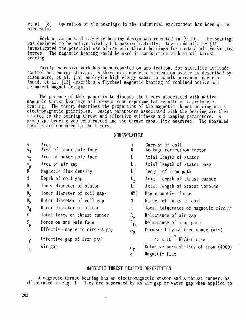
et al. _8]. Operation of the bearings in the industrial environment has been quitesuccesslul
York on an unusual magnetic bearing design was reported in [9,10]. The bearingwas designed to be active axially but passive radially. Lewis and hl]aire [11]investigated the potential use of magnetic thrust bearings for control of transmittedforces. The magnetic bearing would be used in conjunction with an oil thrustbearing.
Fairly extensive work has been reported on applications for satellite attitude
control and energy storage. A three axis magnetic suspension system is described byEisenhaure, et al. [12] employing high energy samarium cobalt permanent magnets.
Anand, et al. [13 l describes a flywheel magnetic bearing of combined active andpermanent magnet design.
The purpose of this paper is to discuss the theory associated with activemagnetic thrust bearings and present some experimental results on a prototypebearing. The theory describes the properties of the magnetic thrust bearing usingelectromagnetic principles. Design parameters associated with the bearing are thenrelated to the bearing thrust and effective stiffness and damping parameters. Aprototype bearing was constructed and the thrust capability measured. The measuredresults are compared to the theory.
NOMENCLATURE
h Area i
A1 Area of inner pole face K
h2 Area of outer pole face L
Ag Area of air gap Lb
B Magnetic flux density Lf
d Depth of coil gap LF
Dt Inner diameter of stator Lt
D2 Inner diameter of coil gap, MMF
D3 Outer diameter of coil gap N
D4 Outer diameter of stator R
F Total force on thrust runner Rg
Fp Force on one pole face RFe
h Effective magnetic circuit gap Po
Effective gap of iron path
Air gap
hf
hg _r
¢
Current in coil
Leakage correction factor
Axial length of stator
Axial length of stator base
Length of iron path
Axial length of thrust runner
Axial length of stator toroids
Magnetomotive force
Number of turns in coil
Total Reluctance of magnetic circuit
Reluctance of air gap
Reluctance of iron path
Permeability of free space (air)
= 4_ x 10 -7 Wb/A-turn-m
Relative permeability of iron (4000)
Magnetic flux
MAGNETIC THRUST BEARING DESCRIPTION
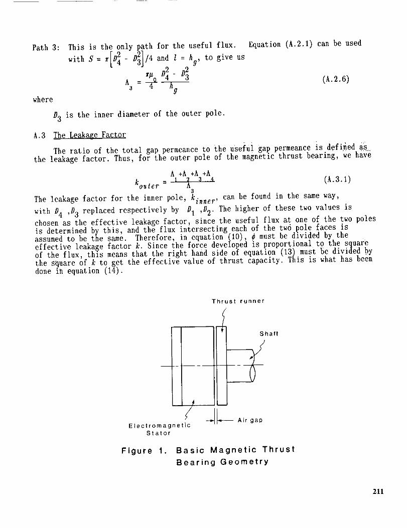
A magnetic thrust bearing has an electromagnetic stator and a thrust runner, asillustrated in Fig. 1. They are separated by an air gap or water gap when applied to
202

a pump. Because the electromagnet is attractive, the thrust bearing must be double
acting to operate successfully for most applications. This is discussed in moredetail later in the paper.
In its simplest form, the electromagnetic stator is formed by an inner and outertoroid connected by a common base. Figure 2 shows an exploded view of the stator,
shaft, and thrust collar of a single acting bearing. All of the magnetic componentsare made of magnet iron. The inner and outer torolds and base may be constructed ofseparate pieces for ease of assembly. They may be held together by screws or other
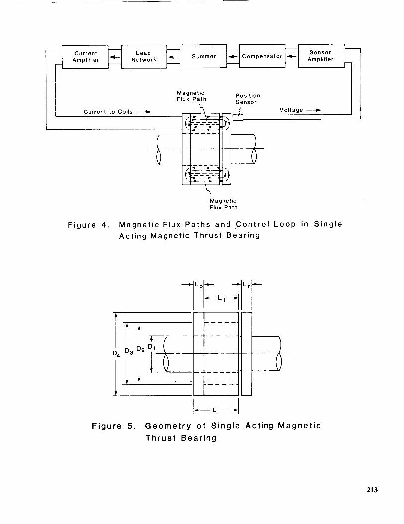
methods. Figure 3 gives a perspective view of the assembled stator. A coil of wireoccupies the space between the inner and outer toroids. This produces the magneticflux in the bearing. Magnetic flux paths are illustrated in Fig. 4 flowing throughthe inner and outer toroids as well as the thrust runner. It is important to provide
a good flux path to avoid leakage from the magnetic components.
The rotating part of the bearing, in its simplest form, is a solid disk made ofmagnet iron and attached to the shaft. Fig. 2 illustrates this construction of thethrust runner. Unlike the rotating part of radial magnetic bearings, the thrust
runner does not cross alternating magnetic flux lines so it does not have to belaminated to reduce eddy currents.
An electronic circuit controls the current in the coils of the stator, as
illustrated in Fig. 4. The axial position of the thrust runner is continuouslymonitored by a sensor. The voltage from the sensor is fed into a sensor amplifier.This in turn enters a compensator, summer, and lead network or other network suitablefor a given application. A current amplifier then supplies the appropriate currentto the coils in the magnetic stator.
A steady state current provides the attractive force between the stator andrunner which gives the bearing its steady load capacity. The bearing by itself has anegative stiffness (discussed later in [2]) so an automatic control circuit isrequired to give the bearing an effective positive stiffness. The position sensor isused to sense the axial position of the shaft and to provide the feedback signal tothe control loop which creates the positive stiffness.
TIIEORETICAL MODEL
The theoretical model of the thrust bearing used in this paper is a onedimensional theory. It is assumed that the flux can be taken as varying only alongthe flux lines. No attempt is made here to do a finite element analysis of themagnetic flux in a two or three dimensional manner.
Several assumptions are made in this derivation for the sake of simplicity:
1. No leakage occurs between the toroids.2 Flux levels are always below saturation.3. Changes in the current are small compared to the steady state level.4. Axial shaft motions are small compared to the steady state air gap.5. A one dimensional model of the magnetic path may be used.
The first assumption is valid if the radial dimension of the space between thetoroids is large compared to the air gap. If not, a leakage factor can be used asdeveloped in Appendix A. The second assumption depends upon the proper design of thethrust bearing for the expected loads. Both assumptions 3 and 4 are generally valid
203
if the bearing is operating properly. The steady state current is usually largecompared to oscillating thrust loads and the axial motions are small relative to thelarge magnetic bearing gap thickness. Finally, a one dimensional model of the
magnetic path provides a reasonable first approximation.
All of the above assumptions may be violated to some extent by actual magneticthrust bearings and probably are. However, that means that more complex analysisneeds to be carried out to supplement the analysis given here. This approach can beused for preliminary design purposes.
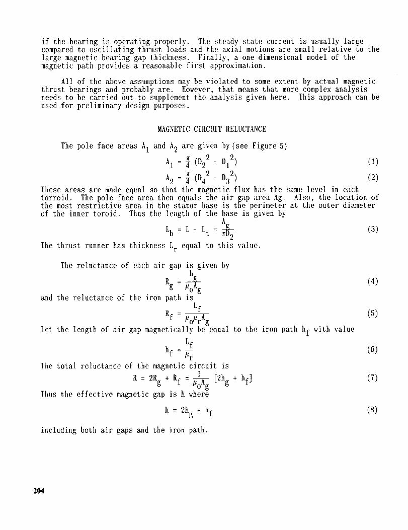
MAGNETIC CIRCUIT RELUCTANCE
The pole face areas A1 and A2 are given by (see Figure 5)
A1 = _ (D22- DI 2)
A2 : ¼ (D42- D32 )
(1)
(2)These areas are made equal so that the magnetic flux has the same level in eachtorroid. The pole face area then equals the air gap area Ag. Also, the location ofthe most restrictive area in the stator base is the perimeter at the outer diameter
of the inner toroid. Thus the length of the base is given byA
Lb = L - Lt : _ (3)
The thrust runner has thickness Lr equal to this value.
The reluctance of each air gap is given byh
Rg : #o_g (4)
and the reluctance of the iron path is
Lf
Rf - Po#r_-_ (5)0
Let the length of air gap magnetically be equal to the iron path hf with value
Lf
hf = _rr (6)
The total reluctance of the magnetic circuit is
+ = 1 [2hg (7)R : 2Rg Rf _ + hf]
Thus the effective magnetic gap is h where
h : 2hg + hf (8)
including both air gaps and the iron path.
204

MAGNETIC FLUX
h magnetomotive force (MMF) is equal to the number of turns in the coil timesthe current
MMF = Ni (9)
The magnetic flux is then found from
¢ = w = (lO)and the flux density is
_o NiB = _-- = (11)
/1_r
This must not exceed the saturation leve_ for the particular magnetic material
involved. Typical values for silicon iron are 1.2 to 1.6 tesla and for rare earthmaterials up to 2.0 tesla.
Often the steady state (also called bias flux level) is chosen as one half ofthe saturation flux level. This value gets the operating point of the thrust bearingup in the linear range of the flux but still leaves operating room for increased fluxfor higher load capacity as needed.
LOAD CAPACITY
Each pole face develops an attractive force with value
FP = 2_-_e -_°A_2h 2 (12)
There are tuo pole faces so the total for_e is
_oAgN2i 2
F = 2Fp = h2 (13)
The actual force is somewhat reduced by leakage effects. A leakage parameter k iscalculated for the thrust bearing geometry. The thrust bearing load capacity is thenmodified to include k as
_ohgN2i 2
F = k2h2 (14)
Appendix A gives the calculation method for k.
In most industrial applications, the thrust bearing must be made double acting.
Figure 6 illustrates the geometry when a single thrust runner is employed in a doubleacting bearing. Other rotating machines emptoy a split double acting thrust bearing.An example is a canned motor pump with one thrust bearing at the pump end of thecanned motor and the other thrust bearing at the opposite end of the motor. The loadcapacity (force acting on the thrust runner) of the double acting thrust bearing is
_oAgN2i 2 _ohhN2i 2
F = [ k2h2 ]2- [ kh2 ] 1 (15)
where 1 denotes the left side and 2 denotes the right side. Clearly, if the twosides are identical the thrust load is zero. [lowever, as a thrust load is applied,
205
the runner will move in the axial direction creating a difference in air gaps. Theautomatic control circuit insures that this thrust bearing will have positiveeffective stiffness and damping dynamic coefficients.
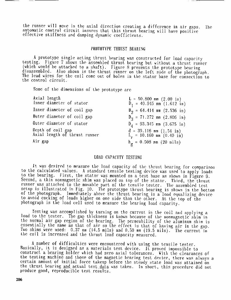
PROTOTYPE TttRUST BEARING
A prototype single acting thrust bearing was constructed for load capacitytesting. Figure 7 shows the assembled thrust bearing but without a thrust runner
(which would beAattached to a shaft). Figure..... 8 presents the DrototvDe bearingdisassembled. 1so shown is the thrust runner on the left side of the photograph.The lead wires for the coil come out of holes in the stator base for connection tothe control circuit.
Some of the dimensions of the prototype are
Axial lengthInner diameter of stator
Inner diameter of coil gap
Outer diameter of coil gap
Outer diameter of stator
Depth of coil gapAxial length of thrust runner
Air gap
L : 50.800 mm (2.00 in)
D 1 : 40.945 mm (1.612 in)
D2 : 64.414 mm (2.536 in)
D3 = 71.272 mm (2.806 in)
D4 = 93.345 mm (3.675 in)
d = 39.116 mm (1.54 in)
Lr = 10.160 mm (0.40 in)
hg = 0.508 mm (20 mils)
LOAD CAPACITY TESTING
It was desired to measure the load capacity of the thrust bearing for comparison
to the calculated values, a standard tensile testing device was used to apply loadsto the bearing. First, the stator was mounted on a test base as shown in Figure 9.Second, a thin nonmagnetic shim was placed on top of the stator. Third, the thrustrunner was attached to the movable part of the tensile tester. The assembled test
s_tup is illustrated in Fig. tO. The prototype thrust bearing is shown in the bottomot the photograph. Immediately above the thrust bearing is a load equalizing deviceto avoid CocKing of loads higher on one side than the other. At the top of the
photograph is the load cell used to measure the bearing load capacity.
Testing was accomplished by turnin_ on the current in the coil and applying aload to the tester. The gap thickness is known because of the nonmagnetic shim inthe normal air gap region of the bearing. The permeability of the aluminum shim is
essentially the same as that of air so the effect is that of having air in the gap.Two shims were used: 0.37 mm (14.5 mils) and 0.50 mm (19.5 mils). The current inthe coil is increased and the thrust load capacity measured.
A number of difficulties were encountered with using the tensile tester.Basically, it is designed as a materials test device. It proved impossible toconstruct a bearing holder which had zero axial tolerances. With the clearances of
the testing machine and those of the magnetic bearing test device, there was always acertain amount of initial force takeup before the steady state load was attained onthe thrust bearing and actual test data was taken. In short, this procedure did notproduce good, reproducible test results.
206

Another type of test, called the drop test, was performed on the thrust bearing.In this test, a known dead load is brought up to a specific distance (separation) tothe face of the thrust bearing. This separation is determined by the particularaluminum shim used for the test. Current is then applied to the bearing ofsufficient level such that the dead load is captured. The dead load and the bearing
is raised by the universal testin$ machine so that the bearing alone is carrying thedead load. Then the current level to the bearing is slowly reduced to the point atwhich the bearing can no longer support the load. The dead load then drops from the
bearin$. The current level at this point is recorded with the value of the dead loadand this yields one point on the LOAD vs CURRENT curve for the particular shim (orequivalent air gap of the bearing).
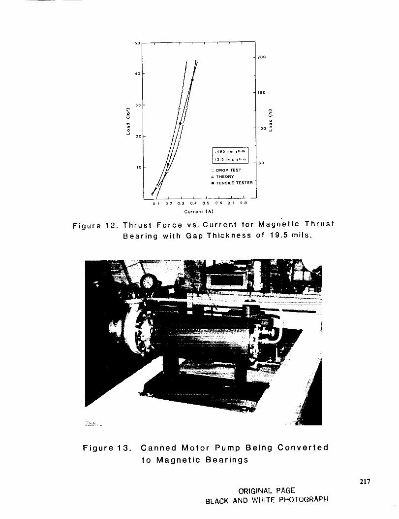
Figure 11 gives the results for the measured load capacity with 0.37 mm (14.5mils). Figure 12 shows similar results with a 0.50 mm (19.5 mil) shim. The theoryused is one dimensional and considers unrolling the toroids and not producingsufficiently accurate leakage factor for this geometry. More consideration needs tobe done to generate more precise leakage factors.
For a significant range (close to our operating range) the slope of thesimplified theory curve agrees fairly well with the experimental work (drop test).The theory is of proper sign in that there are losses that have not been consideredso when further delineation of the flux leakage is produced, the theoretical curvewill be shifted to the right and the slope will decrease.
The theory for the larger gap (clearance) understates the current by some 18
percent which is sufficient for design purposes because the sign of the error isknown. The design conditions for this bearing called for a 0.508 mm (_ 20 mil) gap.This prototype bearing was designed to carry a maximum load of 136 kg (300 lbs) at0.9 amps. A redesign has been made with the new design handling up to 1.8 amp andwith capacity to handle the maximum load.
INDUSTRIAL APPLICATION
The above theory was employed to design and construct a double acting magneticthrust bearing for a canned motor pump. The pump has a single stage overhungcentrifugal impeller and the canned motor is centrally mounted between the bearings.Figure 13 is a photograph of the pump. Both radial and thrust bearings wereoriginally made of carbon. Unfortunately these bearings have relatively shortoperating life, less than one year, in hydrocarbon and other service. The objective
of replacing the original product-lubricated bearings with magnetic bearings is toproduce an extension of life. The objective is five years. As yet there is no dataavailable on the extremely few applications of magnetic bearings to pumps. It is theauthors' understanding that magnetic bearings have been installed in a vertical pumpfor the French Navy but that no results have been made public.
The thrust bearing is split for this canned pump so that one side is between theimpeller and motor and the other side is outboard of the motor. The magneticbearings have the same configuration. They fit in the same components that theoriginal bearings do except for modified bearing housings at both ends. All othercomponents such as the impeller, casing, motor, and shaft have not been replaced orsubstantially modified. Actually, the radial bearings are being replaced also butthis paper is concerned with thrust bearings.
207

The status of this project at this point in time, January 1988, is that thebearings have been designed and are being constructed. Construction will be
completed and testing done over the spring of 1988. A complete pump test loop hasbeen constructed for this purpose. Full operational flow and vibration measurementswere made on the pump with the original bearings before any modifications were made.These will serve as the benchmark measurements.
CONCLUSIONS
This paper describes the theoretical modeling of a magnetic thrust bearing. Thetheory is a one dimensional model of the magnetic flux path through the bearing andresulting forces acting on the thrust runner. Some simplified leakage effects wereincluded in the model. No attempt has been made to develop a more accurate two orthree dimensional finite element model of the bearing as yet.
A single acting prototype was designed with this theory and tested for loadcapacity. The theory over-predicted the load capacity by a significant fraction but
did give a _ood feel for the trends in the bearing. Some problems were encountered
with the initial testin_ which probably resulted in some measurement errors. Thedrop testing procedure has produced more reliable and repeatable results so that therelatively simple theory employed gives a good starting place for design purposes.
Bearings of this type have been designed for a canned motor pump. They arecurrently being constructed and will be tested in the pump in the near future.
ACKNOWLEDGMENTS
This work was funded in part by Kin_sbury, Inc. and the Center for InnovativeTechnology of the Commonwealth of Virginia.
o
.
.
*
.
REFERENCES
Allaire, P. E., tIumphris, R. R., and Kelm, R. D., "Magnetic Bearings For Vibrmtion Reduction and Failure Prevention," Mechanical Failures Prevention Group,40th Meeting, April 16-18, National Bureau of Standards, Gaithersburg, Maryland.
Humphris, R. R., Kelm, R. D., Lewis, D. W., and Allaire, P. E., "Effect of Con-trol Algorithms on Magnetic Journal Bearing Properties," Journal of Engineeringfor Gas Turbines and Power, Trans. ASME, Vol. 108, October 1986, pp. 624-632.
Shimizu, tt. and Taniguchi, 0., "Research on the Control Systems of MagneticBearing," Bulletin of J. S. M. E., Vol. 11, No. 46, 1968, pp. 699-705.
Shimizu, It. and Taniguchi, 0., "Research on the Self-Exciting Vibration ofThrust-Type Magnetic Bearing (Cylindrical Mode)," Bulletin of J. S. M. E.,Vol. 14, No. 72, 1971, pp. 541-549.
Haberman, H. and Liard, G., "An Active Magnetic Bearing System," TribologyInternational, April 1980, pp. 85-89.
208
. Itaberman, It. and Brunet, M., "The Active Magnetic Bearing Enables Optimum Dampingof Flexible Rotor," ASME Paper No. 84-GT-117, ASME Gas Turbine Conference,Amsterdam, June 1984.
, Foster, E. G., Kulle, V., and Peterson, R. A., "The Application of ActiveMagnetic Bearings to a Natural Gas Pipeline Compressor," ASME Paper 86-GT-61,Presented at International Gas Turbine Conference, Dusseldorf, June 8-12, 1986.
o ]lustak, J. F., Kirk, R. G., and Schoeneck, K. A., "Analysis and Test Results ofTurbocompressors Using Active Magnetic Bearings," American Society of Lubrication
Engineers, Preprint No. 86-AM-1A-1, Presented at 41st Annual Meeting, Toronto,May 12-15, 1986.
. Walowit, J. A. and Pinkus, O., "Analytical and Experimental Investigation of
Magnetic Support Systems. Part I: Analysis," Journal of Lubrication Technology,Trans. ASME, Vol. 104, No. 3, July 1982, pp. 418-428.
10. Albrecht, P. R., Walowit, J. A., and Pinkus, 0., "Analytical and Experimental
Investigation of Magnetic Support Systems. Part II: Experimental Investiga-tion," Journal of Lubrication Technology, Trans. ASME, Vol. 104, No. 3, July1982, pp. 429-437.
11. Lewis, D. _., and Allaire, P. E., "Control of Oscillating Transmitted Forces inAxial Thrust Bearings with a Secondary Magnetic Bearing," ASLE Transactions,Vol. 30, No. 1, January 1987, pp. 1-10.
12. Eisenhaure, D. B., Downer, J. R., Bliamptis, T. E., and llendrie, S. D., "ACombined Attitude, Reference and Energy Storage System for SatelliteApplications," AIAA Aerospace Sciences Meeting, Reno, Nevada, January 9-12, 1984.
13. Anand, D. K., Kirk, J. A., and Bangham, M. L., "Simulation, Design andConstruction of a Flywheel Magnetic Bearing," Design Engineering TechnicalConference, ASME, Columbus, Ohio, October 5-8, 1986.
APPENDIX A
A.1 Introduction
The flux path that has been assumed is not the only one for the magnetic thrustbearing, even though it is the only effective one for our needs. There are a numberof other flux paths across the air gap which are traversed by leakage flux. Thisreduces the thrust capability of the bearing, since a part of the magnetomotive forceis wasted to sustain the leakage flux.
A.2 Calculation of Permeances
Before the leakage coefficient can be calculated, it is necessary to compute thepermeance of all the significant flux paths in the air gap. A quite comprehensiveanalysis for the estimation of these permeances has been presented by Roters [12].The following material is based on his treatment of the matter.
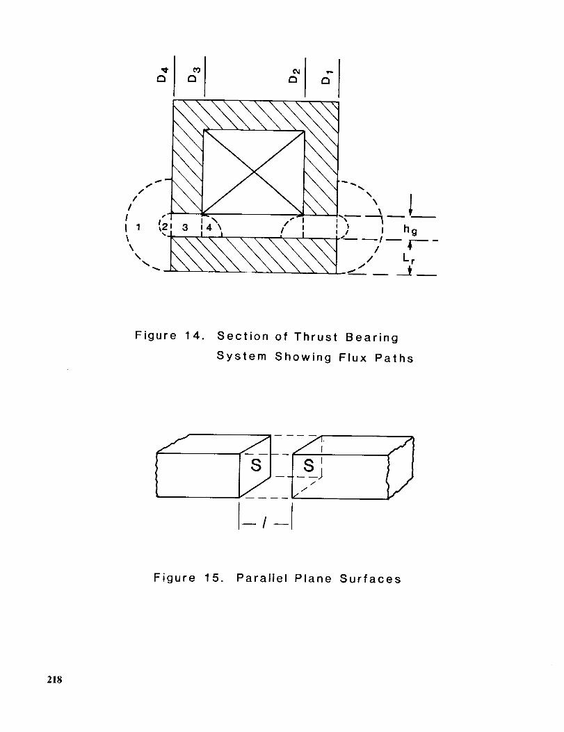
Figure 14 identifies by number the various flux paths in the air gap that arebeing considered here. The two basic formulae that we need are those for thepermeance of a magnetic field between parallel plane surfaces of infinite extent, and
209

that of a magnetic field between non-parallel plane surfaces of infinite extent. For
the former, with reference to Figure 15, the permeance t is given byS
A = 7 (A.2.1)where
S is the surface area of each of the two plane surfaces,
l is the length of the gap between the surfaces,is the permeability oI the medium separating the surfaces.
For a pair of non-parallel surfaces, as shown in Figure 16, a cylindrical shell offlux of radial thickness dr and axial length 1 may be considered. Application ofequation (A.2.1) and subsequent integration over dr gives us
_2 (A.2.2)h = In r
where 1
l, O, r , and r are as shown in Figure 16.2 I
The permeances of the four flux paths of interest can now be determined.
Path 1: Equation (A.2.2) can be used, with
1 = rB4, 0 = r, rl
to give us
where
= hg/2, and r = L + h /22 r ff
A, = PoD41n [1 + 2br/hg ] (A.2.3)
04 is the outer diameter of the bearing,
Lr is the thickness of the thrust collar, and
hg is the air gap between the bearing and the collar.
Path 2:
Path 4:
This flux path is a semicircular cylindrical volume. The mean length of thepath is that of a line drawn midway between the diameter and the
circumference of the semicircle. This equals 1.22hg by graphical measure-
ment. The mean area of the flux path is estimated by dividing the volume ofthe path by this mean length. On applying equation (A.2.1) now, we get
rh 2 (rB,)_ o #
A2- _ 8× 1.22h = 0.26rlto91 (A.2.4)g g
This path has twice the length of path 2 and is identical to it in everyother respect, so that it has twice the permeance-
A4 = 0"52X/_oB3 (A.2.5)
210
Path 3:
where
This is the only path for the useful flux.
g
Equation (A.2.1) can be used
(A.2.6)
9 3 is the inner diameter of the outer pole.
h.3 The Leakage Factor
The ratio of the total gap permeance to the usefui gap permeance is defified a_the leakage factor. Thus, for the outer pole of the magnetic thrust bearing, we have
A +A +h +h
= 1 _ _ 4 (A.3.1)kouter h3
The leakage factor for the inner pole, kinner, can be found in the same way,
with 94 ,9 3 replaced respectively by 91 ,9 2. The higher of these two values is
chosen as the effective leakage factor, since the useful flux at one of the two polesis determined by this, and the flux intersecting each of the tw6 pole faces isassUmed to be the same. Therefore, in equation (10), ¢ must be divided by theeffective leakage factor k. Since the force developed is proportional to the squareof the flux, this means that the right hand side of equation (13) must be divided bythe square of k to get the effective value of thrust capacity. This is what has beendone il equation (14).
Thrust runner
/
I
II
I/Electromagnetic
Stator
_'l Shaft
i
L
Air gap
Figure 1. Basic Magnetic Thrust
Bearing Geometry
211

Base
Figure
CoilInner
toroidOutertoroid
A2
Thrust runner
Shaft
2. Exploded View of Single Acting Magnetic Thrust Bearing
Figure . Perspective View ofStator for MagneticThrust Bearing
212
Current _l LeadAmplifier NetworkSummer I -._- I Compensator
SensorAmplifier
Current to Coils
MagneticFlux Path
__PositionSensor
\MagneticFlux Path
Voltage
Figure 4. Magnetic Flux Paths and Control Loop in Single
Acting Magnetic Thrust Bearing
D4D3
Figure 5. Geometry of Single
Thrust Bearing
Acting Magnetic
213

Coilf
" Shaft
i -\
Stator
Figure 6. Geometry of Double Acting Thrust Bearing
Figure 7. Prototype Thrust Bearing
214
BLACKORIGINAL- PAG'_
AND WHITE PHOTOGRAPH

Figure 8. Disassembled Thrust Bearing
Figure 9. Thrust Bearing Mounted
on Test Base
FiI.,_,..K AND WHITE pI-,_OTOG.R,_pH215

Figure 10. Thrust Bearing in Tensile
Test Device
Figure
cJ3
0J
5O
4O
3O
2O
10
!
,368 mm shim l
I145 mils shim
i I
200
150
Zv
100 0,J
50
DROP TEST
THEORY
@ TENSILE TESTER
0.1 0 2 0.3 04 0 5 0.6 0.7 0 8
Current (A)
11. Thrust Force vs. Current for Magnetic Thrust
Bearing with Gap Thickness of 14.5 mils.
216
cJ_
v
"o
o._J
50 I I
40
30
20
i I
(I.1 0.2
i i I t i I
/
=
/I .495 mm shim19.5 mils sh=m
"J DROP TEST
_. THEORY
• TENSILE TESTER
I t I I L L_
0.3 0.4 0.5 0.6 0.7 0.8
Current (A)
200
150
Zv
'0
100 o._1
5O
Figure 12. Thrust Force vs. Current for Magnetic Thrust
Bearing with Gap Thickness of 19.5 mils.
Figure 13. Canned Motor Pump Being Converted
to Magnetic Bearings
ORIGINAL PAGE
BLACK AND WHITE PHOTO@RAPH
217
,,¢
/i f_ __
! !_. , ", /?3 o4\ / ! _,t 1
o E
tI
\
' II hg
/ LrJ
Figure 14. Section of Thrust Bearing
System Showing Flux Paths
U
Figure 15. Parallel Plane Surfaces
218

_/r _ r//
./0 \
0
Figure 16. Non-parallel Plane Surfaces
219