naatbatt conferencenaatbatt.org/wp-content/uploads/2016/03/dexmet.pdf · naatbatt conference march...
TRANSCRIPT

NAATBATT Conference March 2016
Presented By: John Hart Business Development Manager Power Technologies [email protected]
Value Proposition
for MicroGrid®
Expanded Metal Current Conducting
Foil in Li-ion Cells

MicroGrid® Expanded Metal
Note: Dexmet Does Not Perform Any Internal Testing With Electrode Materials Performance and Cycle Life Data is Provided by Clients & Independent Labs
Manufacture Precision Expanded Metal Foils & Polymers
Established In 1948
Specializing In Thin Metal Foils & Polymers
Custom Designed & Built Expanding Equipment & Tooling
Micro Mesh Materials Fine Metal Foils & Polymers - > 25 Micron - .6mm (.001”-.025”) Opening Sizes -> 25 Micron – 12mm (.001”-.500”)
Primary Market Segments Battery & Fuel Cell Aerospace – Lightning Strike Protection Filtration EMI/RFI Shielding
Company Description

Materials Are Produced Through A Simultaneous “Slit and Stretch” Process – Solid Roll or Sheet Stock of Virtually Any Ductile Metal or Polymer
Overview of Expanded Materials
Ductile Material Being Expanded
Tool Geometry / Profile
Tool Travel (Stroke)
How Expanded Material is Made
3 Strictly Private and Confidential
LWD = Long Way of the Diamond SWD = Short Way of the Diamond Strand Width = Material Thickness Between Openings (Controlled By Feed Rate)
Expanded Terminology
Overall Thickness
MicroGrid® Expanded Metal

Expanded Material is Highly Configurable
– Each characteristic can be altered to meet specific application requirements
Overview of Expanded Materials MicroGrid® Expanded Metal
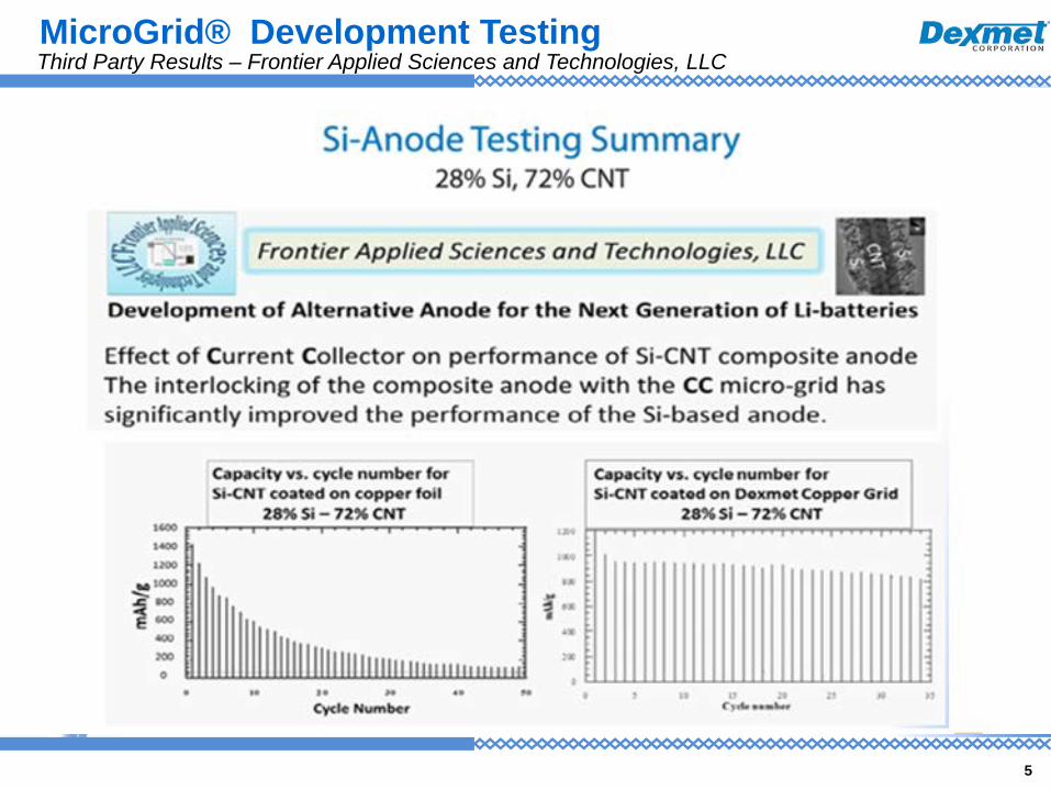
5
Third Party Results – Frontier Applied Sciences and Technologies, LLC MicroGrid® Development Testing

Si Anode on Standard 10 Micron Cu Solid Foil vs. 25 Micron Microgrid ®
Next Phase of Testing – 2Ah Pouch Cells
6
Third Party Results – Si Anode Study MicroGrid® Development Testing
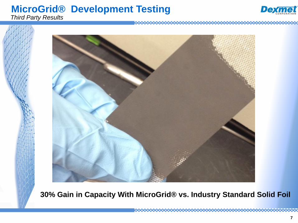
7
30% Gain in Capacity With MicroGrid® vs. Industry Standard Solid Foil
Third Party Results MicroGrid® Development Testing

Li-Plated Standard 10 Micron Cu vs. 25 Micron Cu MicroGrid ® Commercial Cathode Materials. C-Rate 0.7 Charge and 0.5 Discharge
8
Third Party Results – Lithium Anode Study MicroGrid® Development Testing

9
Graph (b) the charging/discharging performance of full cells with graphite anode on solid Cu foil, and cathode on solid Al and Microgrid® (M) Al @ 5C and 10C
Graph (f) The charging/discharging performance of the full-cell at 10C with anode and cathode on solid foil and on Microgrid® (M) current collectors.
Full Cells Produced with NMC and Graphite All Materials Consistent with Exception for Current Conductor Foils 20 Micron Solid Foil vs. 25 Micron MicroGrid ® Expanded Foil
Third Party Results – Ningbo Institute of Material Technology, China MicroGrid® Development Testing

10
During overcharge or over-discharge electrolyte decomposition, passive film formation, active material dissolution, among other phenomena can cause capacity fade. With solid foil each cell layer can become weakest link in the series. _______________________________________________________________________ A porous current conductor enables the cell to fully saturate all layers supplying ions where needed to reduce the potential for capacity fade thus having more electrolyte and Li-ion availability for equilibrium throughout the cell
Cell Layers with Solid Current Conduction Foil
Cell layers with MicroGrid® Current Conduction Foil
Potential For Reducing Capacity Fade MicroGrid® Performance Enhancements

Cu Foil Electrode
11
Reduced De-Lamination Increases Cycle Life MicroGrid® Performance Enhancements
Increased Cycle Life
The MicroGrid® Foil Has Up To 1800 Openings Per Sq. In 1,800 Chemical Bonds Between The Two Sides Of The Coated Foil
There Are 1,800 Chemical Bonds Between The Two Sides of The Coated Foil to Reduce De-Lamination Between Electrode Materials and Foil
Extends Cycle Life and Reduces Dependence on Binder

Proof of Concept: Electrode Slurry Injected To The Underside of The Foil and Pushed Through To Top Surface.
Dual Sided Coating In Single Pass No Laminate Backing Required Potential To Dial In Parameters For Balanced Coating On Both Sides
Top Surface
Photo Courtesy of Megtec Systems Inc.
12
Single Pass Dual Sided Coating – Decreased Processing Time/Reduced De-Lamination MicroGrid® Production Enhancements

13
Soaking And Formation To Saturate Electrolyte Throughout The Electrode Chemistry Can Be A Significant Rate Limiting Step In The Automated Production Of Cells.
MicroGrid® Enables Faster Equilibrium Throughout The Cell
Reducing Formation Time – Increasing Productivity MicroGrid® Production Enhancements

Potential For A Significant Increase In Capacity At Higher C-Rates • Initial Testing Shows Potential For Higher Available Capacity at Higher C-Rates
− “OR” - Reduced Loading To Achieve The Same Capacity −Less weight in Si anode battery
Potential For Reduced De-Lamination At Current Conductor/Electrode Interface
• Better Chemical Bonding To the Electrode Using An Open Area Product − Extending Cycle Life And Potential Reduction In Use Of Binder
Potential Reduction In Capacity Fade • The Porous Foil Allows Li Ions and Electrolyte To Completely Saturate The Multiple Layers Within A Cell
− Reduced Electrolyte Decomposition, Passive Film Formation, Active Material Dissolution And Other Phenomena Caused By Overcharge And Over Discharge
Potential To Buffer The Pulverizing Effects Between Si-Particles At The Foil/Electrode Interface
• The Porous Mesh Is Not Rigid Like Solid Foil Allowing Some Stress Relief Which May Reduce The Amount of Pulverization At The Foil/Electrode Interface
Potential For Increased Battery Life • Marked Increase In Cycle Life By Reducing Capacity Fade and De-Lamination
14
Overview of Performance Considerations MicroGrid® Expanded Metal – Value Proposition

15
Cost Saving Considerations for Production
Reduction In Wetting Time For Electrolyte Formation • The Porous Mesh Allows The Electrolyte To Quickly Saturate The Entire Cell With Electrolyte
• Potential For Single Pass Double Sided Coating • Possibility To Dial In The Proper Injection Parameter To Produce A Double Sided Coating • Equal Electrode Thickness On Both Surfaces Significantly Reducing Production Run Time • Further Testing Is Needed
Overview of Performance Considerations MicroGrid® Expanded Metal – Value Proposition