naca research memorandum - nasanaca research memorandum aerodynamic characteristics of a...
TRANSCRIPT

L
RM A511122
NACA
RESEARCH MEMORANDUM
AERODYNAMIC CHARACTERISTICS OF A LEADING-EDGE SLAT
ON A 350 SWEPT-BACK WING FOR MACH NUMBERS
FROM 0.30 TO 0.88
By John A. Kelly and Nora-Lee F. Hayter
Ames Aeronautical Laboratory Moffett Field, Calif.
NATIONAL ADVISORY COMMITTEE FOR AERONAUTICS
WASHINGTON December 21, 1951
https://ntrs.nasa.gov/search.jsp?R=19930086877 2020-03-20T22:22:25+00:00Z

NACA RN A511123
NATIONAL ADVISORY COMMITTEE FOR AERONAUTICS
RESEARCH MEMORANDUM
AERODYNAMIC CHARACTERISTICS OF A LEADING-EDGE SLAT
ON A 350 SWEPT-BACK WING FOR MACH NUMBERS
FROM 0.30 TO 0.88
By John A. Kelly and Nora-Lee F. Hayter
SUMMARY
The data presented in this report were obtained by North American Aviation, Inc., from an investigation conducted in the Southern California Cooperative Wind. Tunnel. Tests were made over a range of Mach numbers from 0.300 to 0.883 to determine the aerodynamic charac-teristics of a semispan model of a 350 swept-back wing equipped with a leading-edge slat and to gain additional knowledge of the aerodynamic loads and automatic operation of the slat. Lift, drag, and pitching-moment characteristics of the model wing in the presence of a fuselage were measured as well as the pressures acting on the slat in the retracted and the full-open positions. The pressure data were analyzed to ascertain the opening characteristics of the slat for two possible circular-arc slat tracks which could be used for automatic operation of the slat.
Results of the investigation indicated that for angles of attack of the order of 120 and above the slat was effective for increasing the lift coefficient of the wing for Mach numbers up to 0.826. Increasing the Mach number aggravated a decrease in longitudinal stability of the wing caused by extension of the slat • It was found that, for a circular-arc slat track, moving the center of rotation rearward relative to the leading edge of the slat both increased the angle of attack and decreased the range of Mach numbers for which the slat would tend to open auto-matically.
INTRODUCTION
The use of wing sweep and relatively thin wings on present-day airplanes to delay the onset of compressibility effects to higher speeds has resulted In a decrease In the maximum lift coefficient such that the minimum flight speeds are above desirable limits. Since customary

2 NACA RN A51H23
high—lift devices such as trailing—edge flaps are being utilized to the fullest extent to lower the stalling speed, additional devices, to be applied near the leading edge, are being sought to augment the lift and delay the onset of leading—edge separation. It is thought that leading—edge devices also might offer a solution to the problem of controlling the spanwise flow on a swept wing which leads to tip stalling and longi-tudinal instability.
For many years the leading—edge slat has been considered as a device for improving lateral control in stalled flight in addition to being capable of producing high lifts on wings (reference 1). Although some information on straight wings with leading—edge slats has been published (references 2 to 6), very little data are available on swept wings with leading—edge slats (references 7 and 8). To make some infor-mation immediately available on the effects of variations of Mach number on the characteristics of swept wings with leading—edge slats and on the automatic operation of these slats, North American Aviation, Inc., has furnished the NACA with results of tests conducted in the Southern California Cooperative Wind Tunnel
of a semispan model of a 350 swept
wing equipped, with a leading—edge slat.
The data presented herein describe the force and moment character-istics of the model at Mach numbers from 0.300 to 0.883. Force and moment characteristics of the slat as determined from slat pressure distributions are also presented and have been analyzed in an effort to gain some knowledge of the operation of automatic slats.
NOTATION
-
The forces and moments acting on the model were referred to the wind axes and to an assumed center of gravity which lay in the plane of symmetry at a distance of 0.13 mean aerodynamic chord above the quarter point of the mean aerodynamic chord. The forces and moments acting on the leading—edge slat were referred to a system of axes which is in a plane normal to the slat leading edge and the origin of which is the intersection of the leading edge of the slat with the wing reference plane when the slat is in the retracted position. With the slat retracted, the x axis lay in the wing reference plane (fig. 1) and was normal to the slat leading edge, and the z axis was normal to the wing reference plane. When the slat was extended, the axes remained fixed with respect to the slat.

NACA RM A511123 3
General Notation
M Mach number
p free—stream static pressure, pounds per square foot
q free stream dynamic pressure, pounds per square foot
Subscript
U uncorrected values (See Tests and Corrections to the Data.)
Notation for Wing in the Presence of the Fuselage
mean aerodynamic chord, feet
CD drag coefficient 11k%qSj
CL lift coefficient (ft'\ qS )
CM pitching—moment coefficient (pitching moment) qS
R Reynolds number based. on the mean aerodynamic chord
S projected area of semispan wing, square feet
angle of attack of fuselage reference plane, degrees
€ wing incidence relative to fuselage reference plane, degrees
Notation for Leading—Edge Slat
c slat chord normal to leading edge, feet
r (z/c)b Cc slat chord—force coefficient I
-f(Z/C)a iPc
d(z/c) I , positive L J when acting forward parallel to x axis

NACA RM A511123
Cms slat moment coefficient about the leading edge, positive when tending to rotate slat trailing edge up (See appendix.)
Cn slat normal—force coefficient I - / d(x/c) , positive
when acting upward normal toL'o x axis
1/2 CR slat resultant—force coefficient [(Cn)2+(Cc)2]
C8 slat opening—force coefficient (See appendix.)
PI local static pressure on slat, pounds per square foot
I, P1P P pressure coefficient
Ape [P (forward) - P (rearward) ]
)
tPn rP (upper surface) - P (lower surface) 1 [ J x=constant
RR radius of slat track, feet (See fig. 1.)
x distance along x axis behind the slat leading edge, normal to the leading edge, feet
Xp x coordinate of center of pressure
XR x coordinate of center of rotation, feet (See fig. i.)
z coordinate, normal to x axis, feet
Zp z coordinate of center of pressure
ZR Z coordinate of center of rotation, feet (See fig. 1.)
angle between x axis with slat extended and x axis with slat retracted, degrees (See fig. 1.)
line-of-action angle Itan_i (_ a)], degrees

NACA EM A511123 5
Subscripts
a maximum ordinate below x axis
b maximum ordinate above x axis
MODEL AND APPARATUS
The semispan model used in this Investigation consisted of a left wing panel and the corresponding half fuselage (fig. 1). The wing had a taper ratio of 0.513 and an aspect ratio of 4.785. The quarter—chord line was swept back 35.230. The dimensions of the wing are given In table I, and the variation of incidence is shown in figure 2.
In the original wing, the quarter—chord line was swept back 350, and the NACA 0012-64 and 0011-64 sections were laid out normal to this line at the root (station 0) and near the tip (station 6.13), respec-tively. The present wing resulted from adding a constant—chord exten-sion to the trailing edge of the original wing. The sections were modified by drawing straight lines through the new trailing edge and tangent to the original contour.
The wing was equipped with a constant—chord leading—edge slat which was divided into four segments. Movement of the slat was in a direction normal to the leading edge. A section of the slat is shown In figure 1 along with a table of dimensions locating the slat with respect to the center of rotation for two circular—arc tracks. Only track B was actually simulated, but the dimensions for track A were also used in computing the slat opening—force characteristics. The slat was secured in both the retracted and the full—open position by means of metal brackets. A single row of static—pressure orifices was installed in each of the three inner segments of the slat. The orifices were flush with the slat surfaces, and the rows were normal to the leading edge of the slat. The spanwise positions of the rows are indicated in figure 1.
The wing was attached to the tunnel balance system. The fuselage was mounted on the turntable in the tunnel floor, and was separated from the wing by a gap which was sealed in a manner that imposed no restraint on the wing. Therefore, no direct forces acting on the fuselage were measured. The fuselage was provided with boundary—layer ducts in order to minimize the effects of the tunnel—floor boundary layer.

NACA RN A511123
TESTS AND CORRECTIONS TO THE DATA
Over the range of Mach numbers from 0.300 to 0.883, measurements were made of the lift, drag, and pitching moment of the model at various angles of attack with the slat retracted and with the slat fully extended. Distributions of static pressure over the upper and lover surfaces of the three inner slat segments were measured for the same test conditions except at a Mach number of 0.883 with the slat extended. The variation with Mach number of Reynolds number for this model Is shown In figure 3. All tests reported herein were made with the wing in the presence of the fuselage.
The corrections applied to the data to compensate for the blockage of the air strewn by the model are as follows:
M = Mu F i + 0.0091 (1 + 1::1 MU2)]
L (l-Mu)/2 where
7 = 1.14
0.0091 (l)3/2
(2 - MU2)] =[1 +
q
The following jet-boundary corrections were added to the drag-coefficient and angle-of--attack data:
tCD = 0.0183(CL2)
Am = fM(CL)
where fM is given in the table:
M
0.300 1.39 .601 1.146 .801 1.59
• .826 1.63 .851 1.67 .883 1.714
For a Mach number of 0.883, tunnel-w'all static-pressure data Indicated that the tunnel was choked for angles of attack of the model of 60 or

NACA RM A51H23 7
above. The data for these conditions, therefore, are questionable. The tunnel was not choked for Mach numbers of 0.851 or less.
RESULTS AND DISCUSSION
Model Forces and Moments
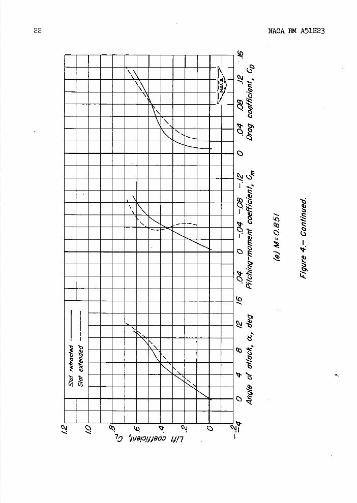
The lift, drag, and pitching-moment characteristics of the model with the slat retracted and with the slat fully extended are presented in figure 4 for various Mach numbers. Some of the curves do not extend through zero lift or maximum lift, consequently a complete analysis and comparison of the effects of slat extension could not be made.
Lift.- As shown by the data in figure I, for angles of attack of the order of 120 and above, the slat appears to have been effective in increasing the lift of the wing for Mach numbers up to 0.826. The slat increased the angle of attack for zero lift about 0.70 for Mach numbers up to 0.801, and an increase of similar magnitude seems likely for the higher Mach numbers although the curves do not cross the axis. For Mach numbers of 0.300 and 0.601 (figs. 4(a) and 4(b)), the lift curves for the wing with the slat extended remained essentially linear to higher angles of attack than did the curves for the wing with the slat retracted, indicating that extension of the slat delayed the occurrence of flow separation over some portions of the wing to a higher angle of attack. This improvement was probably due to a reduction of the peak pressures and of the adverse pressure gradient near the wing leading-edge ,, and also to a beneficial effect on the boundary layer on the upper surface of the wing from the air flow through the gap between the slat and the wing.
For Mach numbers of 0.801 and above (figs. 4(c) through 4(f)), there was a decrease in the slope of the lift curves for the wing with the slat extended prior to any reduction of slope of the curves for the wing with the slat retracted. In the absence of pressure measurements or tuft studies of the flow over the main portion of the wing, it is not possible to explain these changes in lift-curve slope.
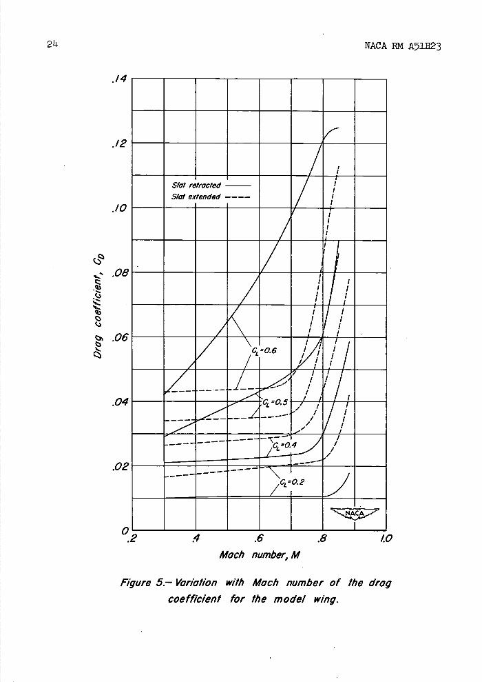
Drag.- The drag characteristics of the model with the slat retracted and with the slat extended are summarized in figures 5 and 6.
As shown in figure 5, extension of the slat increased the drag coeffi- cient and reduced the Mach number for drag divergence for low values of the lift coefficient. However, for the higher lift coefficients, extension of the slat caused the drag coefficient to remain nearly constant up to a Mach number of approximately 0.65 which resulted in a marked reduction in the drag coefficient over the middle portion of the range of Mach numbers for a lift coefficient of 0.5 and over

8 NACA RN A51H23
essentially the entire range of Mach numbers for a lift coefficient of 0.6. Figure 6 shows that extension of the slat resulted in an increase in the lift—drag ratio only above a lift coefficient of approximately 0614 for a Mach number of 0.300 and 0.148 for Mach numbers from 0.601 to 0.851. For the wing with the slat retracted or extended, the maximum values of lift—drag ratio decreased with increasing Mach number. It should be remembered that the lift and drag of the fuselage are not included in the absolute values of the lift—drag ratio.
Pitching moment.— For a Mach number of 0.300 (fig. 4(a)), exten-sion of the slat caused a reduction in the static longitudinal stability of the model wing for the comparable range of lift coefficients. For Mach numbers of 0.601 and above (figs. 4(b) to 14(f)), the pitching—moment coefficients for the model wing with the slat extended indicated a range of neutral or slightly negative stability for low lift coeffi-cients followed by a change to instability as the lift coefficient was increased and subsequently a change back to stability at the higher lift coefficients. The severity of these changes increased and they occurred at progressively lower lift coefficients as the Mach number was increased. For Mach numbers of 0.801 and above, the increased instability with the slat extended coincided approximately with the decreases in lift—curve slopeé mentioned previously.
Slat Pressure Distribution
Some typical graphs of the chordwise and thicknesswise distribu-tions of pressure over the leading—edge slat are presented in figures 7 and 8 for the various test Mach numbers. The thicknesswise distribu-tions of pressure, although presented, are not discussed since they were used only for obtaining force and moment coefficients.
From a comparison of pressure--distribution curves for corresponding test conditions (e.g., segment 1 curves for approximately equal angles of attack from figs. 7(a) and 8(a)), the following results were evident. Extension of the slat reduced the peak pressures near the leading edge as well as the adverse pressure gradient over the upper surface. The location on the slat of maximum pressure (corresponding to stagnation pressure on a straight wing) moved around the leading edge toward the upper surface as the slat was extended. The lower—surface static pressures also were altered considerably by extension of the slat.
With the slat retracted, pressures over Its lower surface in the region from the discontinuity in the slope of the slat contour to the 80—percent—chord point were nearly constant. With the slat extended, the small region of constant pressure on the lower surface (x/c = 0.20 to 0.25 approximately) is believed to be indicative of flow separation

NkCA BM A51H23 9
from the surface at the discontinuity in the slope of the contour and reattachment a short distance beyond. Following reattachment, the flow was retarded - nearly to maximum-pressure conditions for the higher angles of attack - before being accelerated when passing through the gap formed by the trailing edge of the slat and the upper surface of the wing.
The only noticeable effect of the Mach number variations on the slat pressure distributions was a continuous decrease in the leading-edge pressure peak as the Mach number was increased.
Slat Forces and Moments
The force and moment characteristics of the various slat segments in the retracted and in the extended positions, obtained by Integration of the graphs of the pressure distributions, are presented in figures 9 to U for several Mach numbers. Increasing the Mach number caused no consistent change in the normal-force and 'moment characteristics of the slat, but did decrease the slopes of the chordwIse force curves for both positions of the slat. For each Mach number, extension of the slat generally resulted in a sizable reduction of the 'magnitude of the forces and moments and the slopes of the respective curves for a constant angle of attack.
Automatic Slats
Due to the nature of the forces and moments acting on a leading-edge slat, the slat can be made to extend itself automatically as a function of angle of attack without the use of a mechanical actuating mechanism. The path or track the slat is to follow from the retracted to the extended position is dictated by the particular wing and slat design.
The data for the slat of this report have been analyzed for two possible circular-arc tracks to determine the effect of the location of the center of rotation of the track on the slat opening-force char-acteristics. The forces and moments acting on the slat were resolved into a component of force acting tangential to the circular-arc track, that is, the slat-opening force.
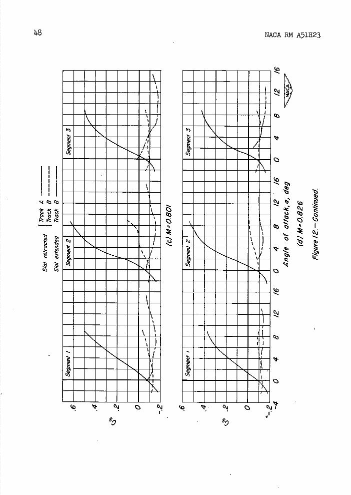
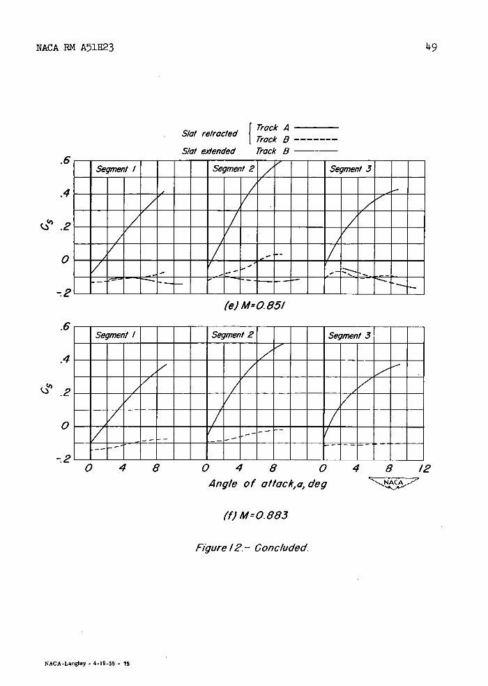
Application of data.- The centers of rotation for the two slat tracks considered are defined in figure 1. The slat opening-force coefficients are shown in figure 12 as a function of angle of attack for track A with the slat retracted and for track B with the slat

10 NACA RN A51323
retracted and fully extended. For negative values of the slat opening-force coefficient, the slat will tend to retract, while for positive values the slat will tend to open. As shown in figure 12, a change from track A to track B would increase the angle of attack for which the slat would first tend to open. Increasing the Mach number had little effect on the angle of attack for which the slat with track A would first tend to open. The opening characteristics of the slat with track B, however, were affected considerably by an increase in Mach number. The data for Mach numbers of 0.300 and 0.601 indicate positive opening-force coeffi-cients for the three inner segments of the slat. The data obtained at higher Mach numbers indicate positive opening-force coefficients only for the second segment of the slat, and these coefficients were small. Therefore, judging from these data, it Is doubtful if the slat with track B would open for a Mach number of 0.801 or above. However, with a positive opening-force coefficient for only one segment, the possibility remains that the slat could open askew to the original leading edge.
The data in figure 12 for the slat with track B Indicate that, for angles of attack above li.°, extending the slat reduced the slat opening-force coefficient Cs. This reduction resulted In an angle-of-attack range for Mach numbers of 0.300 and 0.601 wherein C 5 for the slat In the retracted position was positive, while Cs for the slat in the extended position was negative (figs. 12(a) and 12(b)). Therefore, for these angles of attack, the slat would open only a fraction of its complete travel.
Design considerations.- If the forces and moments acting on a slat are known, the angle of attack for which a positive value of the slat opening-force coefficient first will be realized can be determined readily by the use of a diagram such as is shown. The slat opening-force coefficient C 5 is related to the slat resultant-force coefficient since C5 times the radius of the circular-arc slat track RE must equal CR times the distance from the line of action for CR to the assumed center of rotation. When the line of action for CR falls to the left of an assumed center of rotation the moment about the center of rotation tends to keep the slat retracted. When the line of action for CR falls to the right of the center of rotation, the moment acts to extend the slat. Thus, for a
C. "--,A
\\

NACA RN A51H23
U
center of rotation assumed to lie below the intersection of and between the two lines of action shown in the sketch, the slat would start to open for an angle of attack greater than cz 1 but less than a 2 . Nor-mally the center of rotation would be placed far enough below the wing reference plane to reduce the curvature of the slat track so that the mechanism could be contained completely within the wing.
The variation in numerical value of the slat opening—force coeffi-cient resulting from extension of the slat, due to changes in both mag-nitude and direction of the slat forces, would suggest that a slat path that did not maintain a fixed center of rotation might permit the slat to extend or retract completely in a very small range of angle of attack.
The mass of the slat introduces additional forces which should be considered along with the aerodynamic forces in the design of an auto-matic slat. In accelerating or decelerating flight, the forces due to the mass of the slat will influence the tendency of the slat to open, depending upon the location of the center of gravity of the slat with respect to the center of rotation for the slat track.
CONCLUSIONS
Data contributed by North American Aviation, Inc., from tests on a semispan model of a 350 swept—back wing with a leading—edge slat have indicated the following conclusions:
1. For angles of attack of the order of 120 and above, the slat was effective in increasing the lift coefficient of the wing for Mach numbers up to 0.826.
2. Extension of the slat caused a reduction in the static longi-tudinal stability of the wing for all but the highest lift coefficients, the largest changes in stability occurring at the higher Mach numbers.
3. For a circular-arc slat track, moving the center of rotation rearward relative to the leading edge of the slat both increased the angle of attack and decreased the range of Mach numbers for which the slat first tends to open automatically.
Ames Aeronautical Laboratory, National Advisory Committee for Aeronautics,
Moffett Field, Calif.

ire
12
NACA EM A51H23
APPENDIX
DERIVATION OF EQUATION FOR SLAT OPENING—FORCE COEFFICIENT
rwi
rota//o.1
The summation of moments due to the slat forces tending to extend the slat is given by the following:
EM = [ C c(—zR+zp) - Cn(xR-_xp)] qc
but
Cc(Zp) + Cn(Xp) = Cm(c)
Therefore
EM = [C%( c) - C() - Cn(XR)] qc
The product of the slat opening—force C 5qc and the radius for the circular-arc slat track RR also must equal the sunm]ation of moments:
EM = C5(R)qc
So Cm (c )- ( ZR )- ( XR) Cr =
RR

NACA EM A51U23
13
REFERENCES
1. Lachman, G.: Practical Tests with the "Auto Control Slot." Part I: Lecture. NA.CA TM 593, 1930.
2. Orm.erod., A.: Slotted. R.A.F. 34 Bristol Fighter - Measurement of Forces on Slat in Flight. R. & M. No. 1477, British A.R.C., 1932.
3. Schuld.enfrei, Marvin J.: Wind-Tunnel Investigation of an NACA 23012 Airfoil with a Handley Page Slat and Two Flap Arrangements. NACA ARR, Feb. 1942.
k. Moss, G. F.: Systematic Wind. Tunnel Tests with Slats on a iO% Thick Symmetrical Wing Section (E.Q. 10/40 Profile). Report No. Aero. 2294, British R.A.E., 1948.
5. Gottlieb, Stanley M.: Two-Dimensional Wind-Tunnel Investigation of Two NACA 6-Series Airfoils with Leading-Edge Slats. NACA EM L8K22, 1949.
6. Halliday, A. S., Cox, Miss D. K., Qnd Skelton, W. C.: Model Tests on a High-Lift Aircraft, Folland. E 28/40. R. & M. No. 2428, Part III.- Resultant Force on Wing Slat. British A.R.C., 1950.
7. Fox, A. R.: Tests on a Sweptback Slotted. Wing In the 24 foot Wind Tunnel. Tech. Note No. Aero. 1761, British R.A.E., Apr. 1946.
and
Kettle, D. 3.: Addendum to Technical Note No. Aero. 1761:-Tests on a Sweptback Slotted Wing In the 24 foot Wind. Tunnel. Tech. Note No. Aero. 1761a, British R.A.E., June 1946.
8. Koven, William, and Graham, Robert R.: Wind-Tunnel Investigation of High-Lift and Stall-Control Devices on a. 37 0 Sweptback Wing of Aspect Ratio 6 at High Reynolds Numbers. NACA EM L8D29, 1948.

NACA RM A511123
TABLE I.— MODEL DIMENSIONS
[Wing (complete span)
Area, square feet (includes 5.55 square feet covered byfuselage) . . . ..... . . . . . . . . 31.99
Span, feet . . . . . . . . . ........ • • • • • • 12.39
Mean. aerodynamic chord, feet . . . . . . . . . . 2.69
Aspect ratio . . . . . . . . . . . . . . . . . . . . . . 4.185
'Taper ratio . . . . . . . . . . . . . . . . . . . . . . 0.513
Geometric twist, degrees . . . . . . . . . . . . . . . . . 2.0
Dihedral, degrees . . . . . . . . . . . . . . . . . . . . 3.0
I Slat
Area, square feet . . . . . . • • • , • • • • • • • • •
Chord, feet (constant) . . . . . . . . . . . . . •
aprojected on wing reference plane. bNormal to leading edge of slat.

NACA RN A511123
15
ZR 6t A 0.10 1.25 1.27
8 15 0.42 089 0
Section A—A
Figure /-Dimensions of the semispan model.

16 NACA BN A511123
.1() IC)
5.p' ? 'ODU9P/OU,I ö1!/4f
'I
I I I
0QL
IC)
:! I .. ..-¼ tz

NACA RN A511123
17
St
N.
co 0
9_OI 'i9qwnu Sp10U19y
lb
b
Ilk
0
.,.. II..
Cj0
iz

ONMEMEMEMN mommommommom •...........
•rnurnrnirnuiuiuurn MMMMMEMNMMMMMM-mmmmmmmoommmmm mmmmmmmommoomm .............. •u•u••uuurnuii mmmmmmmommmmmm •.ii.irnrn.u••urnrn •uiu•u•rnurn•u•i
II
mmmmmomommmmmol
MMMMMMOMMEMEME MEMEMEMEMEMEN MEEMEMEMEMEMEN •rnurnrnurn••rniu•• •rnu........... MEMEMEEMEMEMEN •ui••urnurn•urn•u NOMMEMEMEMEMEN
.uuurnuuuuurn •uiuuuuuuuuu•u
uuuuuuuuuu EMEMENEEMMEN
iiuunuuu•u uiuuuuurnuuuu. m.uuuuuuiuuu
uuuuuuuuurnu. •.uuuuuuuuuu• •uuuuuuuuuuuuu
a
q3
I I .1 - I
AZ
q)
S
i
18
NACA RN A511123
Cj c,o -- •-.:
79 '/U9/2/JJ9O7 /1/7

-J
NACA IN A51H23
19
Vj •q)
I.
E
'J.
C
Cj c: Q:i . e c
7 'ivapijjoo /1/7

-.- .'...
'4-
20
NACA P.M A511123
7 ivai.jjjeo. /J)7
•uuiiuu•uiu
•u•••••••
•iuii•••u
... .....
mmmmmmmmmmmm
••iuu•ii•
.....'.....
.......— .
............
mmmmmmmmm
mmmmmmmmmmMM
mmmmommmm
mm
•uiu uiiiu
mmmmmmmmm mm
............
.l........u.
mmmmmmmmmmmm
mmmmmmmmm mm
mmmmmmmmm
ii uu•uuuui
uiuui•uuuu••
MMMEMMMMM mmmmmmmmmm mmmmommomm
m•u•iuuu• mommommom
•uuu•••uumu •uuuii•uuiu

21 NACA RM A511123
79 u9//J000 11.17
MEMMOOMMEM mmommmmmmm
EMMEMMMMMMI EMMEMMMMM
•uuaus.•i .-..u•••• MMEMEMMEMEMM •ui•••••. MMEMMMMMMEMM MMEMMMMEMMEM MMEMMMMMMEEM
II
••UNUU•UU. MMMEMORNMEEM MMEMMMMEMEEM MMEMMMMMEMME MMEOMMMEMMEM RI•••UIUU• MMEMMMMEMMOM ............
MEMMMEMMOM •hILlU•••U•
•i••i.i•i
IU•lUNl••UI MMMEEMMMEM MMMMMERMEM uui•ua••.
MEMEMMMEEMEN IMMMEMEMMOMEM
1
I
.4-.' I Ii
Izi I,
q)
3.
79 11/7 -
22 NACA PIN A511123
IIIIIiIIIIIII \N
N-..
\N ——
I —
L
Q¼\\_
__
-
-
-
'4 -- - - -Csj r I\j
I .'
t

NACA RN A51H23
CsjI • • •• '/U9.12/1J9O /1/7
a•ua•uaaui i
p
MEMMEMMEMMENIr moommommosomom MESIMEMMEMEMEME EMEMMMINEEMM •..'......:..! ••••••u•••••••• MMMMMMMMMMMEMN MEMEMENEEMEMEN MEEMEMEMEME ON EMMEMEMEMEMEMN EMMENEWMEMMEME ••u•a•iuuuuiu mmmmmmmmommmmm mmmmmmmmmmmmmm MMMMIMMMMMMMEOMM MMIMEMEMEMEN No •IUu•UUU••UI!
• •
uu•i•uuu•i •iu•u•u•uuuu•
mmmmmmmmmom
' r•muuuiu •u i
MMMMMMMMMMMMEM mmmmmmmmmmmm
Lc
I
23
ob -
0 I I
ral Itz Iq
:
24
NACA RM A511123
.14
.12
.10
.08
I.06
04
.02
4 .6 .8 10
Mach number, M
Figure 5.— Variation with Mach number of the drag
coefficient for the model wing.
02
S/ct refracted
Slot extended
----
I!' till" III II _________
i'Cl.__
CL
/1/i
iiIi:I lu ll i /O.2

1!cj ONO
Ii
q)
0
.0
¼.
q)
ccj
LZ
C\J•3
I
I
NACA RN A511123
25
'I
I
•1 1III•MI•II
•irn•u••u• rnuu•uu•••u
Cj
co Cj c:
c17 '0/JO) ñOJp-11!7

CL
-I
-2
-I
(a) M=O.300 NACA,7'
U -
U
-4
CL 3
-2 OU
-I
0
dea' --
denol
RR
NACA RN A511123
o Segment /
o Segmen/2
O Segment3
Ct
Figure ?'— The chordw/se and th/cknessw,e distributions of pressure over the leading-edge s/cf in the refracted posit/on.

Q.
A
Q.-2
lb -I
q)
/
IJnfI,7,7npn' cLmhnlc denote unner surftee
denot
-3
CL
I
NACA RN A511123
27
0
• Segment /
• Segment 2
• Segment
(b) M=O.601
Figure 7- Continued

-I
-2
U
£/nf/cQced symbols denote unner surface
denotd
-2
-I
28
NACA RM A511123
o Segment!
o Segment 2
0 Segment 3
(c) M:O.80/
Figure ?— Continued

0
-
Unflogged symbols denote upper surface
F/aaad symbols denote lower surface
Lb 0
A
NACA RN A511123
29
o Segment /
o Segment 2
o Segment 3
(d) M:O.826
Figure 7- Continued

-I
q)
1
q0
0.
30
NACA RN A511123
• Segment/
• Segment 2
• Segment 3
Linflagged symbols denote upper surface flacced symbols denote lower surface
(e) M:O.851 77
Figure 7— Continued

-I
Unflagged Flagged
I choke'-,,
symbols denote upper surface symbols denote lower surface
CL
-I
Q.
. -I
0
el cho/rcu,
NACA RN A511123
31
o Segment/
o Segment 2
' Segment 3
(f) M:O.883
Figure 7- Concluded

-I
aL
L(Inf/oqged symbols denote upper surface
denot
.1.3
-I
32
NACA RN A511123
o Segment /
a Segment 2
o Segmen/3
77
(°) M=O.300
Figure 8- The chordw/se and f/i/cknessw/se distributions of pressure over the leading- edge slat in the extended posit/on.

Q. it
- /
:3
A
Unflogged symbols denote upper surface Flagged symbols denote lower surface
-2
& a
NACA EN A51123
33
o Segmenl
o Segment 2 Segrnent3
(b) M:O.60/
Figure 8.- Continued

0
Q.
Lb
(Inflogged symbols denote upper surface -
dent
I-I
3)4 NACA RN A51H23
• Segment I
• Segment
• Segment 3
(c) M:0.801
Figure 8. -Continued

Q.
-I
P
NACA RM A511123
35
o Segment I
o Segment 2 ) Segment 3
Unulogged symbols denote upper surface Flagged symbols denote lower surface
(d) M:O.826
Figure a- Continued

-I .q3
•1'
El
A
36
NACA RN A511123
o Segment I
o Segment 2
o Segment 3
Unflagged symbols denote upper surface Flacced smbo/s denote lower surface
Q.
QI
(e) MO.85I
Figure 8. - Concluded

NACA RN A51H23
37
1'. '
______•••.•...... kkP 1.uI1iuuuuum iwuiiuui••i
•uuuumuuiuiuuu UIUAV1UIN4IIUU••• MEMO •UUiUi1UIIUU•iU •IUUV FAMMEMMMMMM
Will MMMMMMMMM' % MMMMMMMMMErnA W.M ••l.rn•umr1,v1.1i ••uiri•iiiri•rai ••• ME •u••iiuiuiiiiirii• ••urnmEiMuu•rIdurI•u•
FR% VA;
FAMFAMMM MMEMOMFUM •urjurjiiiriiiijiuiu MMMMMMMEMEMMMEMMMM MEMMMMMMMMMMMMMMM ••rj•iiiri•i•ui••u EMMMEMEMMMMMMEMMM MMMMMMMEMMMMMMM •auii••uu•iu•••u MMMMMMEMMMMMMMMMM •ui•••i•uu•s MMMMMMMMMMMM
0 4 8 12 16 20 for M=0300 Angle of ottac*,a, deg
(a) Segment I.
Figure 9. — Normal-force characteristics of the leading-edge slat.
2.0
1.8
1.6
'.4
I.E
I.0
.8
.6
.4
.2
0
-.2
-.4
-.6
-.8' -4

38
NACA RN A511123
2.
2.
2.
retracted
5/at extended
Tunnel c I. j
Slat
I1HU•UU IU•••IUUWMI•IN•iU ••u•u•uriiiiiuiuui •
• MEN MONEEMM IiUiIM F^J'Na••IuFAJ7AU.!i •uiu•uuriuruauri •u••uuuuiriuvi :AU
•UIU•!111•UIUI AU MENMEMMEMBEEMENEM u•••rniauviurnuiuu 'uuuuriw•iiiii•nirnum
• EMOMMEMMMOMMEM • No WaMMUREUMMEME •uiriiiriiii•u• •
EMEMEMMMM ME EMOMMEMMON ON •uriuiiiiuimirit•u MOMMAMEMBOMMMM EMENOMMENNEWENEME •A•ViVA•VAUIlNiU•U •I•MUUUIU••U MENOMENMEEMEMEMMM MEREMEEMENEREMMEN MENEWOMMEMEN
•i a..u!1.....,Angle of attack, a, deg
(b) Segment 2.
Figure 9.— Continued.

NACA EM A511123
2.6
2.4
2.2
2.0
1.8
1.6
'.4
1.2
1.0
.8
.6
.4
.2
0
-.2
-.4
-.6
39
Slot extended
runnel
Slot retrocted
MMMMMMEMMMM 1' 'u••u•riiui•
MMMMMMMMMMEMMMMMM MMMMMMMMEMMMMMMMM ••UU••UVI•M•UU•l ••u••uiiuiuu•• ••uuu•wriuuiu•ui• •i••u•iiriiwiii•uuuu• MMMMMMMMMMERNMEMM MMMMMOMMMMMOMM ••U•• AU1V1iVAUUI •U•U 11PW1I1!1IIAU •••• 1UHiN•• U
•••vm•u•iiviu•• MMMMMMMOMOMMM MMMMMMMMMMMMMMMMM MMMNMMMMMMMMMMMMM •••1UiNJ1IA•1iUUMl ••UIUIiiIUP1•1MUUU• •iiuuiiiiiriim•i
Ip MFAMNMFJMVAMMPMO MFAMMMMMMMMMMEMMMM MMMMMMMMMMMMMMM ••iuiiui•uu•u MMMMMMMMMMMMMMMMM •••u•ia•muu ••••U•UOU•I•
-4 0 4 8 /2 16 20 for M=0.300 Angle of attack, a, deg
(C) Segment 3.
Figure 9— Concluded.

1.o
1.2
1.0
.8
.6
.4
.2
0
-.2
-4- -4
I
NACA RN A711123
Slat retracted _____UlUHI..1•Ull Slat extended —
iiiriu•u••u•u
u!dh4TT IWIUIII••••
MENEM MENSISIMISIME NONE 0 MEMMEME IMEMMEM MMENMMMMI IMESEMMMMsNIEEMIME INESEMMMMM MENNEN
NAPO PAAPM NONE EMEMEM 00 1ARNIE EMENEWN won 00
EMEMBEEM 2UMENEM EMEMBEEMuwuu OEM
0 4 8 12 16 20 for •30
Angle of attack, a, deg
(a) segment /.
Figure /0. — Chord-force characteristics of the leading- edge slat.

MENEEMEM MEN -MEMENNEEMMMM
MMNMEMENMMMEMMMMM
MMNMMMEEMEMIMEMEEMEME
•un•m•u• MMMMMME 'AMMMMMMMM MMMMMMMMMMMMMMMMM MMMMMMMM 1110M MMMMMMIA'mm SWAM MMMMMMUMMM NERwIss MMMMMvwAuFJurlwrAau MMMrAMAWJMIWIIPJWAU
MMMMMM MMUMMMMM MWANEENAMM N MUNWEEMEN
T URRUURRWAWAIRU
'.4
I.
Ac
41
OR
NACA RM A51H23
41
-4 0 4 8 12 16 20 for M=0.300
Angle of attack, a, deg
t'bI Segment 2.
Figure /0. - Continued.

Slat retracted -SOMMEMMIESSIMM Slat extended - - -EMEMMOMMEMEN runnel choked \N\\\
MEEMEMMINE MORA
NONE MmMmMrArA ESIMEME MEMENOME MENEM MEMENMENNE MEMEMMENEUM MEN MENEM
Wo WOMAN MEN
MENEM MENNEN
mmmmmm
IMMEEMEMMIMMEME
1.0
.8
.6
.2
-.2
42
NACA RM A51E23
-4 0 4 8 12 16 20 for M=0.300
Angle of attack, a, deg
(C) Segment J.
Figure /0. -Concluded

NACA RN A51H23
/.0
.6
rk
-.
IIPMZW -•1 WAUUU.UU
UVAUIUV1!ANAI MEMONONEMUU•1LIWAI• MEEWAMFA M0FAA A AM00 EMENEMEA MVAEMMM EMMEMEMENAF MEMEM MEMEMEMEME MENEM
EMMMMEMMMMM •UIUUIUU•IWAU
-4 0 4 8 12 16 20 for M=0300
Angle of attack, a, c/eq
(a) Segment I.
Figure 1/. - Moment characteristics of the leading - edge slat.

44
NACA RN A511123
rki
.8
.6
S.4
.2
-.2
Slat retracted NEENMENNEEMINSlat extended- EMINJAPSEMENAMEM ,'runnel choked INX •••p NONEMONEEF011 0FAI
WFAMMENEW.Um EN• •JUAUU
No IUWMEAM
UUVAUV1UVMWT1
FNIAMENE20 MEN MENNEN
MEN MREU EMAUAAMUIUUUUU MMEEMMUMME&Z-FA MENNEN ENEWEENEWruu•i•• U•UUIUIUNUI __ ....__.....
-4 0 4 8 /2 16 20 for M=0.300
Angle of attack, a, deg
(b) Segment 2.
Figure II. — Continued.

NACA RM A511123
EMENEENNE ENERESINESSE i ' NESINSEENES • • ••m•uuu NEEMENI!NMENE
.MEMO MWEENS
man NEREMM ISEERE, 4̂4qRMNasqlk N NONEL no 'am MEN
LqN
anon.klhqh, 0 MEN aM
NEENNEWNu MENEENEEN MENEENEEME
%0
swo•
ci
I--
3
0 E
(1)
-S
44 .
1Sl

II Ii I
NACA BM A51H23
4 J 4 .- z
W 07
r)
III
IS
C'4
q3
q)
q)
to
"I
rlz
Cj
C\j ç c Cjc::
.- .-.-

NACA RM A511123
- c: •: "0
•uiiuiu•••i
ONEMEMNON
EMENNEEMEMMU mommommom on •u•i•uutu•u ommumemommom ••R•UU••• •un•••uuuu ••uu•••ui• mommommommom EMEMENEEM No mmmommommumm •..,.'..mu. ••u••inuii NOMMENEENEME WROMEMENIN No ••••••i••u
ME ••Uuuu•ui
mommonomm ••I•UUU•!4U ••Ul••U•••N ............ ............
•ruuu••mu•u •L•Ili••I!iIU ONEREMEEMEN ••iiu••t• UUHUUU•IU No mommommom ••u•uuu•uii •i••uu••i•i lommommommom
- th
Q0 rIQ
I . q
'0
4 co N)
th
: .4 II
I.-.
MENEM MEMENESE Emmommmm MOMMEMEN Emmommm
Emmommom •......i ........ ........ MEMSEEME mu••••uu •iiu••iii
l
mmommom mommom oommomm
•••UUk UUUU•••U ••••iu• ........ ••uuuuuii ••LIUU1Il I.—....
I
•UUI!I •u•i MEMESIS.
Emmommom •u•ui•u
Cj 1
.i
III In
q J-
Il
NACA RN A511123
o. • C%J C3 N N T I• . I•
so4
NACA RN A511123
Slat retracted Track A Track B
Slat extended Track B
• •.•..•.••••••••••••'. .•.••••.••••.•..•.. mmmmmmmmmommmmmmmmmmm •uuii•uui•i•••iu•••• • •••••• IU••• U..... •••••••••••••••••••
(e) M=O.85/
U /rMJUUUU s/!rAfiDIUUUU UUU •iu•uiuuiuiu••u••i• mmmmmummmmmmmmmmmmumm .................... mmmmmmmmmmmmmmmmmmmmm •uri•u•••u•••uiuuu MEMMMMMMMMMMMMMMMMMMM •••............11l... 7 4 8 0 4 8 0 4 5 12
Angle of attcck,a', deg
(1) M=0.883
Figure /2. - Concluded.
NACA-Langley - 4-19-55 - 75