nace rp0198
DESCRIPTION
NACE RP0198.pdfTRANSCRIPT

NACE Standard RPO198-98 Item No. 21084
THE CORROSION SOCIETY
Standard Recommended Practice
The Control of Corrosion Under Thermal Insulation and Fireproofing Materials - A Systems Approach
This NACE International standard represents a consensus of those individual members who have reviewed this document, its scope, and provisions. Its acceptance does not in any respect preclude anyone, whether he has adopted the standard or not, from manufacturing, marketing, purchasing, or using products, processes, or procedures not in conformance with this standard. Nothing contained in this NACE International standard is to be construed as granting any right, by implication or otherwise, to manufacture, sell, or use in connection with any method, apparatus, or product covered by Letters Patent, or as indemnifying or protecting anyone against liability for infringement of Letters Patent. This standard represents minimum requirements and should in no way be interpreted as a restriction on the use of better procedures or materials. Neither is this standard intended to apply in all cases relating to the subject. Unpredictable circumstances may negate the usefulness of this standard in specific instances. NACE International assumes no responsibility for the interpretation or use of this standard by other parties and accepts responsibility for only those official NACE International interpretations issued by NACE International in accordance with its governing procedures and policies which preclude the issuance of interpretations by individual volunteers.
Users of this NACE International standard are responsible for reviewing appropriate health, safety, environmental, and regulatory documents and for determining their applicability in relation to this standard prior to its use. This NACE International standard may not necessarily address all potential health and safety problems or environmental hazards associated with the use of materials, equipment, andior operations detailed or referred to within this standard. Users of this NACE International standard are also responsible for establishing appropriate health, safety, and environmental protection practices, in consultation with appropriate regulatory authorities if necessary, to achieve compliance with any existing applicable regulatory requirements prior to the use of this standard.
CAUTIONARY NOTICE: NACE International standards are subject to periodic review, and may be revised or withdrawn at any time without prior notice. NACE International requires that action be taken to reaffirm, revise, or withdraw this standard no later than five years from the date of initial publication. The user is cautioned to obtain the latest edition. Purchasers of NACE International standards may receive current information on all standards and other NACE International publications by contacting the NACE International Membership Services Department, P.O. Box 218340, Houston, Texas 7721 8-8340 (telephone +1 281/228-6200).
Approved 1998-2-20 NACE International P.O. Box 21 8340
Houston, Texas 77218-8340 + 1 281 /22&6200
ISBN 1-57590-049-1 O1 998, NACE International
COPYRIGHT NACE InternationalLicensed by Information Handling ServicesCOPYRIGHT NACE InternationalLicensed by Information Handling Services

m bY52981 0503798 129 =
RP0198-98
Foreword
This NACE standard recommended practice provides the current technology and industry practices for mitigating corrosion under thermal insulation and fireproofing materials, a problem termed corrosion under insulation (Cul) in this standard. Because this corrosion problem has many facets and impacts several technologies, a systems approach has been adopted. This standard is intended for use by corrosion-control personnel and others concerned with the corrosion under insulation and/or fireproofing of piping and other plant equipment. This will concern chiefly the chemical process, refining, and power generation industries.
This standard was prepared by NACE Work Group T-5A-30a on Corrosion Protection Under Insulation, with the assistance of Task Group T-6H-31 on Coatings for Carbon and Austenitic Stainless Steel Under Insulation and ASTM"' Committee C-16.40.3 on Corrosion Under Insulation. Work Group T-5A-30a supports NACE Task Group T-5A-30 on Corrosion Under Thermal Insulation, a component of NACE Unit Committee T-5A on Corrosion in Chemical Processes. This standard is issued by NACE Group Committee T-5 on Corrosion Problems in the Process Industries, the sponsor of T-5A. Task Group T-6H-31 supports NACE Unit Committee T-6H (Coating Materials for Atmospheric Service), a component of NACE Group Committee T-6 on Protective Coatings and Linings.
The work group has organized the standard into sections by function. Each section was written by specialists in that subject. These specialists are industry representatives from firms producing, specifying, designing, and using thermal insulation and fireproofing products on refinery and petrochemical equipment and piping.
In NACE standards, the terms shall, must, should, and may are used in accordance with the definitions of these terms in the NACE Publications Style Manual, 3rd ed., Paragraph 8.4.1.8. Shall and must are used to state mandatory requirements. Should is used to state that which is considered good and is recommended but is not absolutely mandatory. May is used to state that which is considered optional.
('I American Cociety for Testing and Materials (ASTM), 100 Barr Harbor Dr., West Conshohocken, PA 19428-2959.
NACE International i
COPYRIGHT NACE InternationalLicensed by Information Handling ServicesCOPYRIGHT NACE InternationalLicensed by Information Handling Services

RPO198-98
NACE International Standard
Recommended Practice
The Control of Corrosion Under Thermal Insulation and Fireproofing Materials . A Systems Approach
Contents
1 . General ..................................................................................................................... 1 2 . Corrosion Mechanisms .............................................................................................. 1 3 . Mechanical Design .................................................................................................... 7 4 . Protective Coatings ................................................................................................. 16 5 . Insulation. Fireproofing. and Accessory Materials .................................................... 19 6 . Inspection and Maintenance .................................................................................... 23 References .................................................................................................................. 27 Bibliography ................................................................................................................ 28 Figure 1: Effect of Temperature on Steel Corrosion in Water ....................................... 3 Figure 2: Typical Vessel Attachments Where Water May Bypass Insulation ................. 8 Figure 3: Attachment to Piping Where Water May Bypass Insulation ............................ 8 Figure 4: Vessel Insulation Support Ring. the Problem and the Solution ..................... 10 Figure 5: Vertical Vessel Bottom Support Ring Minimizing Water Accumulation ......... 10 Figure 6: Vessel-Stiffening Ring Insulation Detail ....................................................... 11 Figure 7: Center Nozzle at Top Head of Vessel .......................................................... 11 Figure 8: Common Nameplate Insulation Detail .......................................................... 12 Figure 9: Seal-Welded Cap on Insulation for Personnel Protection ............................. 12 Figure 1O:Double-Pipe Heat Exchanger Insulation Penetrated by C-Channel Support . 13 Figure 11 :Protrusions Through Jacketing ..................................................................... 13 Figure 12:Pipe Supports Without Protrusions .............................................................. 14 Figure 13:Cold Service Pipe Support Without Continuous Vapor Barrier ..................... 14 Figure 14:Cold Service Pipe Support with Continuous Vapor Barrier ........................... 15 Figure 15:Pipe Insulation Penetrated by Column Fireproofing ..................................... 16
NACE International
COPYRIGHT NACE InternationalLicensed by Information Handling ServicesCOPYRIGHT NACE InternationalLicensed by Information Handling Services

RPO198-98
Section 1: General
1 .I Corrosion under insulation (CUI) has been occurring for as long as hot or cold equipment has been insulated for thermal protection, conservation, or process stabilization. The destructive results and nature of the corrosion mechanism are not referenced in the literature until the 1950s. As more problems have been experienced, concern and interest have built around this subject. Many articles and symposium papers have been published since 1983 as interest and activity in CUI have increased. The increased activity was driven largely by many occurrences of severe CUI resulting in major equipment outages, production losses, and unexpected maintenance costs in refineries, gas plants, and chemical plants.
1.2 To correct these problems, companies have devel- oped their own criteria and approaches to the prevention of CUI. When comparing the various approaches, it is evident that there are many similarities, some differences, some new ideas, and some old ideas that have stood the test of performance. This standard incorporates the experience of many companies throughout the oil, gas, and chemical industries.
1.3 The first ASTM standard relevant to CUI was ASTM C 692,‘ adopted in 1971 and originally titled “Evaluating the Influence of Wicking Type Thermal Insulations on the Stress Corrosion Cracking Tendency of Austenitic Stainless Steels.”
1.4 A symposium was held jointly b NACE, ASTM, and
speakers from industries worldwide in October 1983. The papys were published in 1985 as ASTM Publication STP 880.
Materials Technology Institute (MTI)‘ 3( on this subject with
1.5 The first NACE report on CUI was written in 1989 by Task Group T-6H-31 as publication 6H189.3 NACE Task Group T-5A-30 was organized shortly thereafter to serve as a forum for further discussion regarding CUI. In addition to reviews of the corrosion mechanisms, perspectives on such CUI topics as methods for mitigation, insulation materials, and inspection were often exchanged. While corrosion engineers were becoming knowledgeable about CUI, ASTM Committee C-16 was preparing standards for testing insulation with a propensity to cause chloride stress corrosion cracking (SCC) of austenitic stainless steel. These two groups interacted but proceeded to develop their standards and information separately.
1.6 Although most of the attention has been focused on corrosion under thermal insulation, fireproofing materials also function, at least in part, as insulation applied between the critical steel structure and a potential fire. Other fire protection mechanisms initiated as endo- thermic reactions within the fireproofing material during a fire, such as sublimation, hydro-regeneration, and intumescence, are known to augment the insulating role of the fireproofing. The mechanisms also add unique considerations to the discussion of the chemistry at the wet steel interface. A discussion of corrosion mechanisms, the root cause of failure, and corrosion prevention is the same for corrosion under both insulation and fireproofing.
1.7 The consensus is that the basic solution to prevent- ing CUI is the use of a high-quality protective coating. It is the recommendation of this committee that whenever CUI is a consideration, a protective coating should be employed to protect the equipment before it is insulated.
Section 2: Corrosion Mechanisms
2.1 Carbon Steel
Carbon steel corrodes, not because it is insulated, but because it is contacted by aerated water. The role of insulation in the CUI problem is threefold. Insulation provides:
(a)
(b)
An annular space or crevice for the retention of water and other corrosive media; A material that may wick or absorb water; and
(c) A material that may contribute contaminants that increase or accelerate the corrosion rate.
The corrosion rate of carbon steel may vary because the rate is controlled largely by the metal temperature of the steel surface and contaminants present in the water. These factors and others are reviewed below.
2.1.1 Effects of Water, Contaminants, and Temperature
(‘) MatezTechnoÏogy Institute (MTI), 1215 Fern Ridge Parkway, Suite 116, St. Louis, MO 63141-4401.
NACE International 1
COPYRIGHT NACE InternationalLicensed by Information Handling ServicesCOPYRIGHT NACE InternationalLicensed by Information Handling Services

RP0198-98
2.1.1.1 Sources of Water Under Insulation
The two primary water sources involved in CUI of carbon steel are:
(a) (b) Condensation.
Water infiltrates from such external sources as the following:
Infiltration from external sources; and
(a) Rainfall; (b) Drift from cooling towers; (c) Condensate falling from cold service
equipment; (d) Steam discharge; (e) Process liquids spillage; (f) Spray from fire sprinklers, deluge systems,
and washdowns; and (9) Condensation on cold surfaces after vapor
barrier damage.
External water enters an insulated system primarily through breaks in the weatherproofing. The weatherproofing breaks may be the result of inadequate design, incorrect installation, mechanical abuse, or poor maintenance prac- tices.
Condensation results when the temperature of the metal surface is lower than the atmospheric dew point. While infiltration of external water can be reduced and sometimes prevented, insulation systems cannot be made vapor tight, so condensation as a water source must be recognized in the design of the insulation system.
2.1.1.2 Contaminants in Water Under Insulation
The role of contaminants is twofold:
(a) Contaminants can increase the conductiv- ity and/or corrosiveness of the water environment; and
(b) Contaminants can reduce the protection offered by the corrosion product scale on the carbon steel surface.
There are two primary classes of contaminants in water under insulation:
(a) Contaminants external to the insulation materials; and
(b) Contaminants leached from the insulation materials.
Chlorides and sulfates are the principal contami- nants found under insulation. Whether their source is external or internal, they are particu-
larly detrimental because their respective metal salts are highly soluble in water, and these aqueous solutions have high electrical conduc- tivity. In some cases, hydrolysis of the metal salts can cause localized corrosion because of development of low pH in anodic areas.
External contaminants are generally salts that come from sources such as cooling tower drift, acid rain, and atmospheric emissions. The external contaminants are waterborne or air- borne and can enter the insulation system directly through breaks in the weatherproofing. External contaminants also enter the insulation materials indirectly by depositing on the jacket surface. Subsequent wetting then carries the concentrated salts to breaks in the weather- proofing. The salts enter the insulation system by gravity or the wicking action of absorbent insulation. The salt concentrations gradually increase as water evaporates from the carbon steel surface.
Contaminants contained in the insulation materials are well documented. Chloride is generally one of the contaminants, unless the insulation product is declared “chloride free.” Chlorides can be present in almost all com- ponents of the insulation system, including the insulation, mastic, and sealant. As water enters the insulation system, the contaminants are leached from the material and concentrate as water evaporates from the carbon steel surface. If the insulation materials contain water- leachable acidic compounds, then the pH of the water will be lowered, resulting in increased corrosion.
2.1.1.3 Effect of Temperature
Service temperature is an important factor affecting CUI of carbon steel because two opposing factors are involved:
(a) Higher temperature reduces the time water is in contact with the carbon steel; however, Higher temperature tends to increase the corrosion rate and reduce the service life of protective coatings, mastics, and sealants.
(b)
Figure 1 illustrates the corrosiveness of water versus temperature. In an open system, the oxygen content of the water decreases as the temperature increase^.^ As a result, above approximately 80°C (1 76”F), the corrosion rate of carbon steel in aerated water begins to decrease. However, in a closed system, the corrosion rate of carbon steel in water continues
2 NACE International
COPYRIGHT NACE InternationalLicensed by Information Handling ServicesCOPYRIGHT NACE InternationalLicensed by Information Handling Services

to increase as the water temperature increases4 Field measurements of the corrosion rate of carbon steel corroding under insulation confirm that the rate increases with temperature in a manner similar to that of a closed ~ys tem.~ This is relevant to the corrosion mechanism occurring under insulation, where the thin film of water, while not under pressure, is oxygen-saturated. Thus, the same oxygen cell corrosion mechan- ism is taking place as in a closed system. The corrosion rates from field measurements are somewhat greater than laboratory rates, due to the airborne or insulation-carried salts in the field. Such salts can influence the corrosion rate because of their high solubility in water and the attendant increase in the conductivity of the water film.
1.0-40
0.75 h
2 E E v
a (II Oc 0.5 c O v)
c
.- P 8 o 0.25
-- 30
--20
-- 1 O
RPO198-98
Inspection of equipment has shown that carbon steel operating in the temperature range of -4°C (25°F) to 150°C (300°F) is at the greatest risk from CUI. Equipment that operates continuously below -4°C (25°F) usually remains free of corro- sion. Corrosion of equipment operating above 150°C (300°F) is reduced because the carbon steel surface is warm enough to remain dry. However, corrosion will tend to occur at those points of water entry into the insulation system where the temperature is below 150°C (300°F) and when the equipment is idle.
The service temperature of equipment often varies, and the corrosion rate of carbon steel under insulation will be affected by:
- Closed System (oxygen held in system)
---- Open System (oxygen free to escape) '
O Chemical Plant Measurements of Corrosion Under Insulation
O O
1 50 200 ("FI
O 20 40 60 80 loo (OC) dp' 1 ? O I I , ,
O
Temperature
Figure 1 Effect of Temperature on Steel Corrosion in Water
NACE International
~ ~~ ~
3
COPYRIGHT NACE InternationalLicensed by Information Handling ServicesCOPYRIGHT NACE InternationalLicensed by Information Handling Services

Intermittent or variable operation of equip- ment; Temperature variations along the height or length of the equipment; Temperature at which attachments to equipment operate; and Idle or mothballed conditions.
2.1.2 Effects of Insulation Material
2.1.2.1. Effects of Types of Insulation
CUI of carbon steel is possible under all types of insulation. The insulation type may only be a contributing factor. The insulation characteris- tics with the most influence on CUI are:
(a) Water-leachable salt content in insulation that may contribute to corrosion, such as chloride, sulfate, and acidic materials in fire retardants;
(b) Water retention, permeability, and wetta- bility of the insulation; and
(c) Foams containing residual compounds that react with water to form hydrochloric or other acids.
Because CUI is a product of wet metal exposure duration, the insulation system that holds the least amount of water and dries most quickly should result in the least amount of corrosion damage to equipment.
Corrosion can be reduced by careful selection of insulation materials. Materials that may be cheaper on an initial cost basis may not be more economical on a life-cycle basis if they allow corrosion. For more detailed information about insulation materials, refer to Section 5.
2.1.2.2 Role of Weather Barrier and Vapor Barrier Materials
Weather barriers and vapor barriers are applied to insulation to keep the insulation dry. Mastics and sealants are materials used to close open- ings around protrusions in the insulation system. Weather barrier and vapor barrier materials are critical components in the insulation system, because they must seal and protect the insula- tion. Their durability against mechanical abuse, ultraviolet (UV) degradation, water, and chemi- cals is of prime importance. In addition, these materials must not contain leachable compo-
nents that increase the corrosiveness within the insulation system.
In the long term, the weather barriers and vapor barriers break down or are damaged to the point that they can no longer keep the insulation dry. Therefore, maintenance and inspection of weatherproofing are essential to ensure the integrity of the i nsulation/f i reproofi ng system.
For more information on this subject, refer to Section 5.
2.1.2.3 Effect of Design
Equipment design and mechanical details have an important influence on CUI of carbon steel. Several undesirable design features that influ- ence CUI include:
(a)
(b)
Shapes that naturally retain water, such as flat horizontal surfaces, vacuum rings, and insulation support rings; Shapes that are difficult or impractical to weatherproof properly, such as gussets, I-beams, and other structural components; Shapes that funnel water into the insula- tion, such as angle-iron brackets; Other items that cause interruption in the weatherproofing, such as ladder brackets, nozzle extensions, decking, and platform and pipe supports; and
(e) Protrusions through insulation on cold service equipment where temperature gradients from cold to ambient will occur.
(c)
(d)
The more breaks there are in equipment surface, the more likely that water will enter or bypass insulation and drain poorly from equipment. Therefore, high-quality protective coatings must be used to protect steel and should be included in the design specifications.
For more detailed information on this subject, refer to Section 3.
2.2 Austenitic Stainless Steel
The stainless steel alloys susceptible to SCC are generally classified as the 18-8s: austenitic alloys containing approximately 18% chromium, 8% nickel, and the balance iron. Besides the basic alloy UNS'31 S30400, these stainless alloys include (among others) the molybdenum-containing grades (UNS S31600 and S31700), the carbon stabilized grades (UNS
(3) Metais and Alloys in the Unified Numbering System (latest revision), a joint publication of the American Society for Testing and Materials (ASTM) and the Society of Automotive Engineers Inc. (SAE), 400 Commonwealth Drive, Warrendale, FA 15096.
4 NACE International
COPYRIGHT NACE InternationalLicensed by Information Handling ServicesCOPYRIGHT NACE InternationalLicensed by Information Handling Services
RPO198-98
S32100 and S34700), and the low carbon grades (UNS S30403 and S31603).
To combat SCC, many variations of the basic 18-8 stainless steels have been developed. These are the higher-nickel, chromium, and molybdenum-containing alloys (super stainless steels), and the lower-nickel, higher-chromium duplex alloys. These alloys are more resistant to SCC and have been found to be resistant to SCC under thermal insulation.
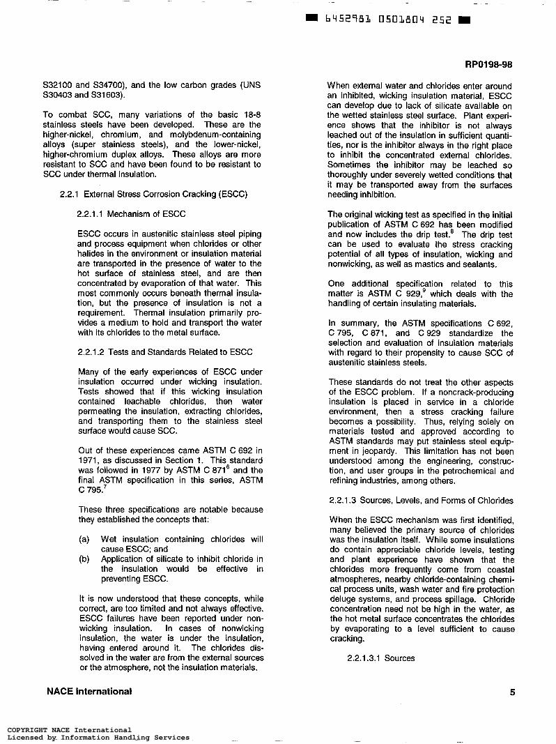
2.2.1 External Stress Corrosion Cracking (ESCC)
2.2.1.1 Mechanism of ESCC
ESCC occurs in austenitic stainless steel piping and process equipment when chlorides or other halides in the environment or insulation material are transported in the presence of water to the hot surface of stainless steel, and are then concentrated by evaporation of that water. This most commonly occurs beneath thermal insula- tion, but the presence of insulation is not a requirement. Thermal insulation primarily pro- vides a medium to hold and transport the water with its chlorides to the metal surface.
2.2.1.2 Tests and Standards Related to ESCC
Many of the early experiences of ESCC under insulation occurred under wicking insulation. Tests showed that if this wicking insulation contained leachable chlorides, then water permeating the insulation, extracting chlorides, and transporting them to the stainless steel surface would cause SCC.
Out of these experiences came ASTM C 692 in 1971, as discussed in Section 1. This standard was followed in 1977 by ASTM C 8716 and the final A2TM specification in this series, ASTM c 795.
These three specifications are notable because they established the concepts that:
(a) Wet insulation containing chlorides will cause ESCC; and
(b) Application of silicate to inhibit chloride in the insulation would be effective in preventing ESCC.
It is now understood that these concepts, while correct, are too limited and not always effective. ESCC failures have been reported under non- wicking insulation. In cases of nonwicking insulation, the water is under the insulation, having entered around it. The chlorides dis- solved in the water are from the external sources or the atmosphere, not the insulation materials.
When external water and chlorides enter around an inhibited, wicking insulation material, ESCC can develop due to lack of silicate available on the wetted stainless steel surface. Plant experi- ence shows that the inhibitor is not always leached out of the insulation in sufficient quanti- ties, nor is the inhibitor always in the right place to inhibit the concentrated external chlorides. Sometimes the inhibitor may be leached so thoroughly under severely wetted conditions that it may be transported away from the surfaces needing inhibition.
The original wicking test as specified in the initial publication of ASTM C 692 has been modified and now includes the drip test.* The drip test can be used to evaluate the stress cracking potential of all types of insulation, wicking and nonwicking, as well as mastics and sealants.
One additional specification related to this matter is ASTM C 929,’ which deals with the handling of certain insulating materials.
In summary, the ASTM specifications C 692, C795, C 871, and C 929 standardize the selection and evaluation of insulation materials with regard to their propensity to cause SCC of austenitic stainless steels.
These standards do not treat the other aspects of the ESCC problem. If a noncrack-producing insulation is placed in service in a chloride environment, then a stress cracking failure becomes a possibility. Thus, relying solely on materials tested and approved according to ASTM standards may put stainless steel equip- ment in jeopardy. This limitation has not been understood among the engineering, construc- tion, and user groups in the petrochemical and refining industries, among others.
2.2.1.3 Sources, Levels, and Forms of Chlorides
When the ESCC mechanism was first identified, many believed the primary source of chlorides was the insulation itself. While some insulations do contain appreciable chloride levels, testing and plant experience have shown that the chlorides more frequently come from coastal atmospheres, nearby chloride-containing chemi- cal process units, wash water and fire protection deluge systems, and process spillage. Chloride concentration need not be high in the water, as the hot metal surface concentrates the chlorides by evaporating to a level sufficient to cause cracking.
2.2.1.3.1 Sources
NACE international 5
COPYRIGHT NACE InternationalLicensed by Information Handling ServicesCOPYRIGHT NACE InternationalLicensed by Information Handling Services

RPO198-98
Sources of chlorides fall into two categories: insulating materials and external sources. A systems approach will develop strategies to combat both categories.
2.2.1.3.1 .I Insulating materials include insulation, mastics, sealants, adhe cives, and cements. Failures after only a few years of operation are typically associated with insulating materials containing high levels of leachable chlorides.
2.2.1.3.1.2 External sources include rain, coastal fog, wash water, fire and deluge system testing, and process leaks or spills. Failures due to intro- ducing chlorides from external sources tend to occur after five years or more of service. These sources account for most of the chloride-induced failures.
2.2.1.3.2 Levels
Experience has shown that insulating materials with as little as 350 ppm chloride have been identified near ESCC locations. Deposits near ESCC events have been found with as little as 1,000 ppm chloride. It is useful to consider these levels when determining acceptable chloride levels for insulating materials.
2.2.1.3.3 Forms
Sodium chloride is the most prevalent chloride salt found in CUI events. When found in sufficient quantities, it causes SCC of austenitic stainless steel. Other sources of chloride ions known to be aggressive include chlorine, hydrogen chloride gas, hydrochloric acid, hydrolyzed organic chlo- rides, and thermally decomposed polyvinyl chloride (PVC). Likewise, acidic conditions in combination with chloride will be more aggressive than neutral or basic conditions. It is useful to consider these observations when specifying insulating materials.
2.2.1.4 Effect of Temperature
Temperature has a twofold effect. First, as stated above, at elevated temperature water evaporates as it contacts the hot stainless steel surface. This evaporation can concentrate the chloride salts, allowing them to be deposited on the metal surface. Second, as temperature increases, the rate of the corrosion reaction increases, and the time decreases for initiation and propagation of ESCC.
Most ESCC failures occur when metal tempera- ture is in the "hot water" range: 50°C to 150°C (120°F to 300°F). Failures are less frequent when metal temperature is outside this range. Below 50°C (120°F) the reaction rate is low, and the evaporative concentration mechanism is not significant. Above 150°C (300"F), water is not normally present on the metal surface, and failures are infrequent. Equipment that cycles through the water dew point is particularly susceptible. Water present at the low tempera- ture evaporates at the higher temperature. During each temperature cycle the chloride salts dissolved in the water concentrate on the surface.
2.2.1.5 Role of Stress
In order for SCC to develop, sufficient tensile stress must be present in the stainless steel. If the tensile stress is eliminated or sufficiently reduced, the cracking will not occur. The threshold stress required to develop cracking depends somewhat on the cracking medium. Most mill products, such as sheet, plate, pipe, and tubing contain enough residual processing tensile stresses to develop cracks without applied stresses. When 18-8 stainless steels are cold formed and welded, additional residual stresses are imposed. As the total stress rises, the potential for SCC increases. Attempts to control SCC by reducing the tensile stress by thermal treatment are not practical.
2.2.2 Effects of Types of Insulation
The solution to ESCC of stainless steel does not lie with the type of insulation chosen. Industry experi- ence and testing have shown that cracking occurs under all types of insulation materials. Insulations that absorb water are particularly troublesome in that they hold water and slowly allow the concentration mechanism to proceed. Insulations that do not absorb water are frequently specified in an attempt to lessen the problem; but without other preventive measures, cracking may still occur.
Polyurethane foam, polyisocyanurate foam, and phenolic foam do not provide immunity to ESCC, especially when used in the hot water range. Residual chlorine or bromine compounds used in manufacturing the foam may leach out and hydro- lyze, forming an acidic condition that accelerates the cracking of 18-8 stainless steels.
For more detailed information on insulation materials, refer to Section 5.
2.2.3 Effects of Mastics and Sealants
6 NACE International
COPYRIGHT NACE InternationalLicensed by Information Handling ServicesCOPYRIGHT NACE InternationalLicensed by Information Handling Services

RPOI 98-98
If water could be excluded, the insulation would stay dry, and ESCC would not occur. While this sounds like a reasonable approach toward prevention, in practice it is extremely difficult to prevent water ingress. In fact, once insulation becomes wetted, the weather barriers, mastics, and sealants make water escape difficult, so the insulation remains wet. Also, mastics and sealants may contain water-leachable chlorides that can contribute to ESCC problems.
2.2.4 Effect of Design
Design steps to minimize water ingress are beneficial but not normally adequate to prevent cracking. Some amount of water entry into the insulation system will eventually occur. High-quality immersion grade protective coatings as outlined later in this standard shall be specified to protect the stainless steels.
For more information on mastics and sealants, refer to Section 5.
For additional information on design, see Section 3, and for protective coatings, see Section 4.
Section 3: Mechanical Design
3.1 Poorly designed or applied insulation systems and protrusions through thermal insulation permit water to bypass the insulation, thereby corroding the substrate metal." Metal also corrodes when weather barriers and vapor barriers break down after vessels and piping are put in service and are exposed to the weather. This often results in structural failures, unplanned or extended shutdowns, and unscheduled replacement of equipment. Insulation system life can be prolonged, and substrate metal corrosion can be reduced by better design of protrusions, attachments, and supports associated with vessels and piping.
3.2 Thermal Insulation System Design
Equipment and piping are insulated for any of the following reasons:
(a) (b) Process control; (c) Personnel protection; (d) Sound control; (e) Condensation control; and (f) Fire protection.
Heat conservation and/or freeze protection;
Insulated surfaces for carbon steel operating continuously above 150°C (300°F) or below -4°C (25°F) and for austenitic stainless steel operating continuously above 150°C (300°F) or below 50°C (120°F) do not present major corrosion problems. However, equipment and piping operating either steadily or cyclically between these temperatures can present significant corrosion problems. These problems are aggravated by selecting inadequate insulation materials and by improper insula- tion design. Guidelines for proper design to control corro- sion in thermal insulation systems are presented below.
3.2.1 Specification Requirements
Insulation specifications are critical requirements for insulation system design and installation work.
They control material and application requirements. Loosely written specifications with insufficient material descriptions and application requirements may result in costly repairs during construction or after the plant is operational.
Common specification flaws to be avoided are:
(a) Incorrect application of materials: e.g., open- cell or wicking-type insulation materials, such as calcium silicate, and fibrous products specified for below-ambient temperature appli- cations.
(b) Product specification by using a generic name without stating the properties required for the intended service.
(c) Improper and unclear application methods: e.g., incorrect multilayer schedules, lack of expansion joints, missing vapor barriers, and incorrect insulation securement methods.
A specification needs to be complete and detailed. It must clearly describe materials, application, and finishing requirements. If a service needs special attention from an insulation standpoint, it should be stated in the specification. For more information on insulation materials, see Section 5.
3.3 Effect of Equipment and Piping Attachment Design
The design of equipment and piping attachments is an important part of insulation system design. The shape, geometry, and orientation of attachments can allow moisture or rainwater to bypass the insulation and to concentrate at the attachment point. Examples of such attachments are shown in Figures 2 and 3. Attention to details such as these is important in order to produce a high-quality insulation system.
NACE International 7
COPYRIGHT NACE InternationalLicensed by Information Handling ServicesCOPYRIGHT NACE InternationalLicensed by Information Handling Services

RPO198-98
7 Nozzle
Figure 2 Typical Vessel Attachments Where Water May Bypass Insulation
f -Pressure Gauge
Caulking Compound
Note: Jacketing Seam /- atTop
Insulation-’
Figure 3 Attachment to Piping Where Water May Bypass Insulation
Attachment relies on caulking compound only.
8 NACE International
COPYRIGHT NACE InternationalLicensed by Information Handling ServicesCOPYRIGHT NACE InternationalLicensed by Information Handling Services
bLi52182 0502808 î T B
RPO198-98
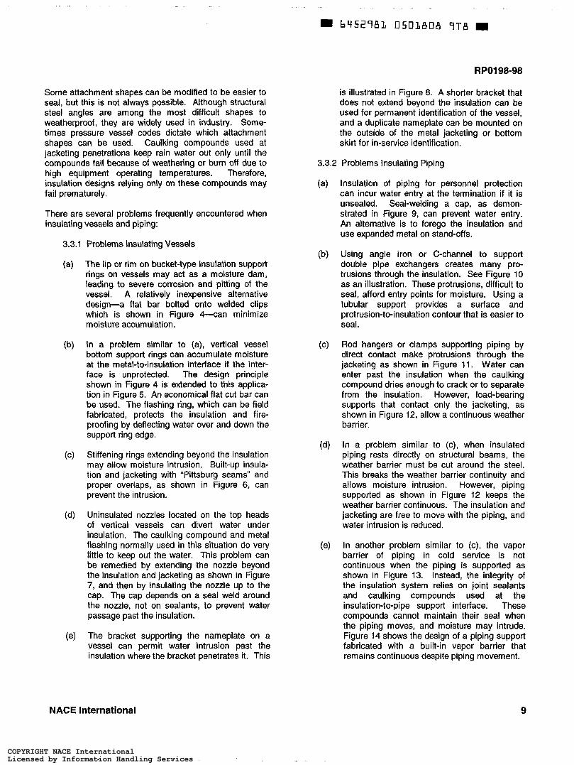
Some attachment shapes can be modified to be easier to seal, but this is not always possible. Although structural steel angles are among the most difficult shapes to weatherproof, they are widely used in industry. Some- times pressure vessel codes dictate which attachment shapes can be used. Caulking compounds used at jacketing penetrations keep rain water out only until the compounds fail because of weathering or burn off due to high equipment operating temperatures. Therefore, insulation designs relying only on these compounds may fail prematurely.
There are several problems frequently encountered when insulating vessels and piping:
3.3.1 Problems Insulating Vessels
(a) The lip or rim on bucket-type insulation support rings on vessels may act as a moisture dam, leading to severe corrosion and pitting of the vessel. A relatively inexpensive alternative design-a flat bar bolted onto welded clips which is shown in Figure h a n minimize moisture accumulation.
(b) In a problem similar to (a), vertical vessel bottom support rings can accumulate moisture at the metal-to-insulation interface if the inter- face is unprotected. The design principle shown in Figure 4 is extended to this applica- tion in Figure 5. An economical flat cut bar can be used. The flashing ring, which can be field fabricated, protects the insulation and fire- proofing by deflecting water over and down the support ring edge.
(c) Stiffening rings extending beyond the insulation may allow moisture intrusion. Built-up insula- tion and jacketing with “Pittsburg seams” and proper overlaps, as shown in Figure 6, can prevent the intrusion.
(d) Uninsulated nozzles located on the top heads of vertical vessels can divert water under insulation. The caulking compound and metal flashing normally used in this situation do very little to keep out the water. This problem can be remedied by extending the nozzle beyond the insulation and jacketing as shown in Figure 7, and then by insulating the nozzle up to the cap. The cap depends on a seal weld around the nozzle, not on sealants, to prevent water passage past the insulation.
The bracket supporting the nameplate on a vessel can permit water intrusion past the insulation where the bracket penetrates it. This
(e)
is illustrated in Figure 8. A shorter bracket that does not extend beyond the insulation can be used for permanent identification of the vessel, and a duplicate nameplate can be mounted on the outside of the metal jacketing or bottom skirt for in-service identification.
3.3.2 Problems Insulating Piping
(a) Insulation of piping for personnel protection can incur water entry at the termination if it is unsealed. Seal-welding a cap, as demon- strated in Figure 9, can prevent water entry. An alternative is to forego the insulation and use expanded metal on stand-Offs.
(b) Using angle iron or C-channel to support double pipe exchangers creates many pro- trusions through the insulation. See Figure 10 as an illustration. These protrusions, difficult to seal, afford entry points for moisture. Using a tubular support provides a surface and protrusion-to-insulation contour that is easier to seal.
(c) Rod hangers or clamps supporting piping by direct contact make protrusions through the jacketing as shown in Figure 11. Water can enter past the insulation when the caulking compound dries enough to crack or to separate from the insulation. However, load-bearing supports that contact only the jacketing, as shown in Figure 12, allow a continuous weather barrier.
(d) In a problem similar to (c), when insulated piping rests directly on structural beams, the weather barrier must be cut around the steel. This breaks the weather barrier continuity and allows moisture intrusion. However, piping supported as shown in Figure 12 keeps the weather barrier continuous. The insulation and jacketing are free to move with the piping, and water intrusion is reduced.
(e) In another problem sirnilar to (c), the vapor barrier of piping in cold service is not continuous when the piping is supported as shown in Figure 13. Instead, the integrity of the insulation system relies on joint sealants and caulking compounds used at the insulation-to-pipe support interface. These compounds cannot maintain their seal when the piping moves, and moisture may intrude. Figure 14 shows the design of a piping support fabricated with a built-in vapor barrier that remains continuous despite piping movement.
NACE International 9
COPYRIGHT NACE InternationalLicensed by Information Handling ServicesCOPYRIGHT NACE InternationalLicensed by Information Handling Services

RPO198-98
Insulation
Area of oinina of
Corrosion Problems with Bucket-Type Insulation Support Ring
,-Vessel
Flat Bar-Type Support Ring Eliminates Moisture Accumulation
Figure 4 Vessel Insulation Support Ring, the Problem and the Solution
Figure 5 Vertical Vessel Bottom Support Ring Minimizing Water Accumulation
10 NACE International
COPYRIGHT NACE InternationalLicensed by Information Handling ServicesCOPYRIGHT NACE InternationalLicensed by Information Handling Services

RPOI 98-98
61
Figure 6 Vessel-Stiffening Ring Insulation Detail
Seams prevent water intrusion.
Insulation
Figure 7 Center Nozzle at Top Head of Vessel
Extended and Insulated with Seal-Welded Cap
NACE International 11
COPYRIGHT NACE InternationalLicensed by Information Handling ServicesCOPYRIGHT NACE InternationalLicensed by Information Handling Services

RPO198-98
, I/ ,- inruiotlon
inaulaiion 1
Nomoplote
Figure 8 Common Nameplate Insulation Detail
Water may enter through bracket penetration.
L Pipe
2.1 m to O cm (7 R to O in.) above
4--.-- Metal Jacketin
Caulking Compound
Figure 9 Seal-Welded Cap on Insulation for Personnel Protection
Cap prevents water entry.
12 NACE International
COPYRIGHT NACE InternationalLicensed by Information Handling ServicesCOPYRIGHT NACE InternationalLicensed by Information Handling Services

RP0198-98
support Ponlbh d r y pdnt for r o h r
Figure 10 Double-Pipe Heat Exchanger Insulation Penetrated by C-Channel Support
Water entry points shown
Pipe Supported by Rod Hanger
support
Figure 11 Protrusions Through Jacketing
NACE International 13
COPYRIGHT NACE InternationalLicensed by Information Handling ServicesCOPYRIGHT NACE InternationalLicensed by Information Handling Services

RPO198-98
Figure 12 Pipe Supports Without Protrusions
Caulking compound
I I
Figure 13 Cold Service Pipe Support Without Continuous Vapor Barrier
14 NACE International
COPYRIGHT NACE InternationalLicensed by Information Handling ServicesCOPYRIGHT NACE InternationalLicensed by Information Handling Services

RPOl98-98
\
- / / I -’.u \ Figure 14
Cold Service Pipe Support with Continuous Vapor Barrier
Also in cold service, insulation and vapor barriers are often penetrated for improved access to equipment lying close to the insulation, such as instrument connections, drain-valve hand wheels, and valve packing glands. These penetrations can allow moisture intrusion and condensation. The problem is avoided by extending valve stems and instrument connections above the insulation.
Clearance for insulation between piping and adjacent structures can be insufficient due to incorrect pipe spacing, unexpected thickness of steel column fireproofing, and unexpected piping movement. This inadequate clearance often permits moisture to bypass weather- proofing and vaporproofing, as shown in Figure 15. The only cure is to design adequate space for insulation. Design considerations should include effects of adjacent structures, piping movement, and expansion joints.
Electrical conduit suspended from piping or penetrating its insulation presents insulation sealing difficulties for both hot and cold service. Moreover, in extremely hot service, the conduit may suffer overheating damage; in cold service, the conduit may corrode. The remedy is to avoid penetrating piping insulation; e.g., suspend conduit from structural members.
Providing adequate piping clearances, attend- ing to attachment geometry, and understanding
incidental corrosion can preclude many of the problems described above. Knowledge of various insulation materials and their installa- tion requirements, along with knowledge of equipment and piping, is necessary for corro- sion control.
3.4 Weather Barrier and Vapor Barrier Design
In insulation system design, selection of weather barriers and vapor barriers is as important as selection of thermal insulation. While it is easy to say, “Keep water out,” in practice, keeping water out is not always feasible. Weather barriers and vapor barriers break down due to chemical attack, sunlight, mechanical damage, and galvanic corrosion. Caulking compounds and mastics used during construction for sealing jacket seams degrade in sunlight and at temperatures exceeding the materials’ recommended use limits. Vapor barriers also degrade in sunlight, creating cracks and open seams that allow moisture penetration.
In cold service, thermal insulations rely on vapor barriers to keep out moisture. With the possible exception of an all-welded metal sleeve enclosure, there is no perfect vapor barrier. Mastic vapor barriers without metal jacketing require periodic inspections to check for signs of mechanical damage, aging, cracking, delaminations, and broken seals. Unattended repairs shorten insulation life and promote corrosion. Metal jackets should be avoided over vapor barriers on cold service insulation unless needed for protection of the insulation.
NACE International 15
COPYRIGHT NACE InternationalLicensed by Information Handling ServicesCOPYRIGHT NACE InternationalLicensed by Information Handling Services

m b 4 5 2 9 8 1 0501815 O38
RPO198-98
In warm service, weather barriers are normally metallic. They are fabricated from roll jacketing and can have many seams. Sometimes seams are installed on top surfaces or have improper overlaps. Overlap seams are more vulnerable to foot traffic damage on horizontal lines, vessel heads, and tank tops when thin metallic jacketing is used over fibrous insulation.
The use of dissimilar metals in metallic jacket design in the presence of moisture should be avoided as this often causes galvanic corrosion.
3.5 Insulation System Design
Insulation designs for rigid and semirigid materials may require expansion joints, depending on operating temperatures and sizes of equipment and piping. Failure to employ these joints at the required locations in the insulation can lead to its uncontrolled movement. As a
result, weather barriers and vapor barriers break down. This can allow migration of water into the insulation and lead to corrosion. Normally, insulation design for flexible materials, such as fibrous blanket, does not require expansion joints.
System designers may fail to allow for movement of insulation caused by piping expansion. For example, based on the coefficients of thermal expansion at -73°C (-100OF) and 20°C (70°F), cellular glass insulation expands about the same amount as carbon steel, whereas cellular foam expands about nine times more than carbon steel. When the insulated system cools, joints will compress in cellular glass but open in cellular foam. Therefore, cellular foams (such as a polyurethane system) require more expansion joints. Also, to control the lateral migration of water vapor, polyurethane insulated systems need more frequent vapor stops than do cellular glass systems.
Figure 15 Pipe Insulation Penetrated by Column Fireproofing
4.1
16
Section 4: Protective Coatings
Scope reduction insulation systems and cementitious fire- proofing. Protective coatings have been recognized
4.1.1 This section presents information for the and accepted and are recommended as a highly selection of protective coatings for carbon steel and effective method of protecting insulated metallic austenitic stainless steel under thermal and/or noise substrates such as these steels from corrosion.
NACE International
COPYRIGHT NACE InternationalLicensed by Information Handling ServicesCOPYRIGHT NACE InternationalLicensed by Information Handling Services
RP0198-98
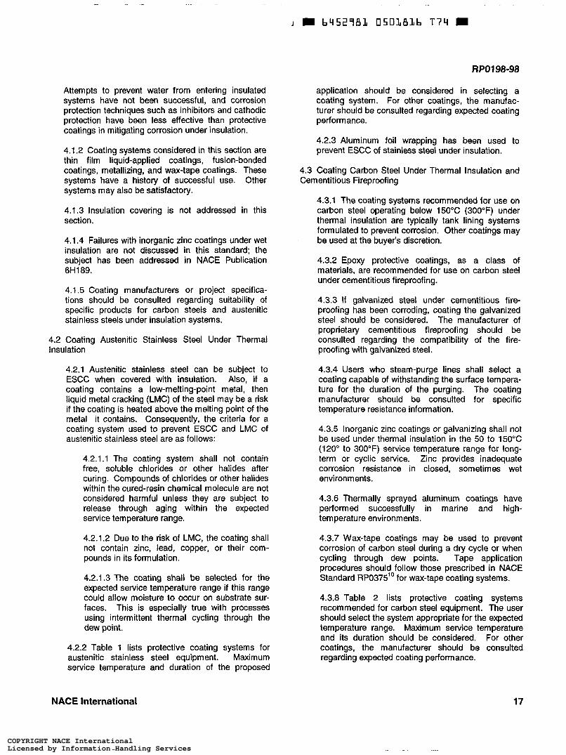
Attempts to prevent water from entering insulated systems have not been successful, and corrosion protection techniques such as inhibitors and cathodic protection have been less effective than protective coatings in mitigating corrosion under insulation.
4.1.2 Coating systems considered in this section are thin film liquid-applied coatings, fusion-bonded coatings, metallizing, and wax-tape coatings. These systems have a history of successful use. Other systems may also be satisfactory.
4.1.3 Insulation covering is not addressed in this section.
4.1.4 Failures with inorganic zinc coatings under wet insulation are not discussed in this standard: the subject has been addressed in NACE Publication 6H189.
4.1.5 Coating manufacturers or project specifica- tions should be consulted regarding suitability of specific products for carbon steels and austenitic stainless steels under insulation systems.
4.2 Coating Austenitic Stainless Steel Under Thermal Insulation
4.2.1 Austenitic stainless steel can be subject to ESCC when covered with insulation. Also, if a coating contains a low-m elti ng-poi nt m etal, then liquid metal cracking (LMC) of the steel may be a risk if the coating is heated above the melting point of the metal it contains. Consequently, the criteria for a coating system used to prevent ESCC and LMC of austenitic stainless steel are as follows:
4.2.1.1 The coating system shall not contain free, soluble chlorides or other halides after curing. Compounds of chlorides or other halides within the cured-resin chemical molecule are not considered harmful unless they are subject to release through aging within the expected service temperature range.
4.2.1.2 Due to the risk of LMC, the coating shall not contain zinc, lead, copper, or their com- pounds in its formulation.
4.2.1.3 The coating shall be selected for the expected service temperature range if this range could allow moisture to occur on substrate sur- faces. This is especially true with processes using intermittent thermal cycling through the dew point.
4.2.2 Table 1 lists protective coating systems for austenitic stainless steel equipment. Maximum service temperature and duration of the proposed
application should be considered in selecting a coating system. For other coatings, the manufac- turer should be consulted regarding expected coating Performance.
4.2.3 Aluminum foil wrapping has been used to prevent ESCC of stainless steel under insulation.
4.3 Coating Carbon Steel Under Thermal Insulation and Cementitious Fireproofing
4.3.1 The coating systems recommended for use on carbon steel operating below 150°C (300°F) under thermal insulation are typically tank lining systems formulated to prevent corrosion. Other coatings may be used at the buyer’s discretion.
4.3.2 Epoxy protective coatings, as a class of materials, are recommended for use on carbon steel under cementitious fireproofing.
4.3.3 If galvanized steel under cementitious fire- proofing has been corroding, coating the galvanized steel should be considered. The manufacturer of proprietary cementitious fireproofing should be consulted regarding the compatibility of the fire- proofing with galvanized steel.
4.3.4 Users who steam-purge lines shall select a coating capable of withstanding the surface tempera- ture for the duration of the purging. The coating manufacturer should be consulted for specific temperature resistance information.
4.3.5 Inorganic zinc coatings or galvanizing shall not be used under thermal insulation in the 50 to 150°C (120” to 300°F) service temperature range for long- term or cyclic service. Zinc provides inadequate corrosion resistance in closed, sometimes wet environments.
4.3.6 Thermally sprayed aluminum coatings have performed successfully in marine and high- temperature environments.
4.3.7 Wax-tape coatings may be used to prevent corrosion of carbon steel during a dry cycle or when cycling through dew points. Tape application procedures should follow those prescribed in NACE Standard RP0375” for wax-tape coating systems.
4.3.8 Table 2 lists protective coating systems recommended for carbon steel equipment. The user should select the system appropriate for the expected temperature range. Maximum service temperature and its duration should be considered. For other coatings, the manufacturer should be consulted regarding expected coating performance.
NACE International 17
COPYRIGHT NACE InternationalLicensed by Information Handling ServicesCOPYRIGHT NACE InternationalLicensed by Information Handling Services

RPO198-98
Table 1 Protective Coating Systems for Austenitic Stainless Steels Under Thermal Insulation
SUBSTRATE TEMPERATURE SURFACE SURFACE PRIME COAT"' FINISH COAT'" RANG E(*) PREPARATION PROFILE@)
Austenitic Stainless -45 to 60°C NACE NO. 3@) 25 to 50 pm i30 pm (5 mils) of high- N/A Steel System No. 1 (-50 to 140°F) (1 to 2 mils) build (HB) epoxy
Austenitic Stainless -45 to 150°C NACE No. 3 25 to 50 pm 150 pm (6 mils) of 150 pm (6 mils) of Steel System No. 2 (-50 to 300°F) (1 to 2 mils) epoxylphendic or high- epoxylphendic or high-
temperaturerated amine temperaturerated amine cured coal tar epoxy
Austenitic Stainless -45 to 37OOC NACE No. 3 25 to 50 pm 50 pm (2 mils) of air-dried 50 pm (2 mils) of air-dried Steel System No. 3 (-50 to 700°F) (1 to 2 mils) m d i i e d silicone coating modified silicone coating
Austenitic Stainless -45 to 760°C NACE No. 3 40 to 65 pm 1 O0 pm (4 mils) siloxane 100 pm (4 mils) siloxane steel System NO. 4(E)
cured coal tar epoxy
(-50 to 1,400"~) (1.5 to 2.5 mils)
(A) The temperature range shown for a coating system is that over which the system is designed to maintain its integrity and capability to perform as specified when correctly applied. However, the user may determine whether any coating system is required, based on corrosion characteristics of stainless steel at certain temperatures. (') A typical minimum and maximum surface profile is specified for each substrate. Acceptable profile range may vary, depending on substrate and
Coating thicknesses are typicai dry film values. Temperature ranges are typical for the coating system. For protective coatings not listed, of coating. Coating manufacturer's recommendations should be followed.
s ecifications and coating manufacturer's recommendations should be followed. ($NACE No. 3/SSPC-SP 6 (latest revision), "Commercial Blast Cleaning" (Houston, TX: NACE, and Pittsburgh, PA: SSPC). (E) This system is not recommended for cyclic senrice characterized by rapid temperature fluctuations.
Table 2 Protective Coating Systems for Carbon Steels Under Thermal Insulation and Cementitious Fireproofing
SUBSTRATE TEMPERATURE SURFACE SURFACE PRIME COAT@) INTERMEDIATE FINISH COAT'^) REMARKS RANGE(^) PREPARATION PROFILE(^) COAT")
Carbon Steel -45 to 60°C NACE No. 2ID' 50 to 75 pm 130 pm (5 mils) high- N/A 130 pm (5 mils) HB NIA
Carbon Steel -45 to 60°C NACE No. 2 50 to 75 pm NIA System No. 2 (-50 to 140°F) (2 to 3 mils) fusion-bonded epoxy applicaîion only
Carbon Steel -45 to 60°C NACE No. 2 50 to 100 Km 180 to 250 pm (7 to 15 to 20 pm (0.5 to 75 pm (3 mils) of US. Navy System No. 3 (-50 to 140°F) (2 to 4 mils) 10 mils) metallized 0.75 mil of MIL-P- MIL-P-24441/2'F' Standard DOD-
System No. 1 (-50 to 140°F) (2 to 3 mils) build (HB) epoxy epoxy
N/A 300 pm (12 mils) In-shop
aluminum 24441/11) epoxy EPA STD-2138''' polyamide (EPA) followed by 75 pm (3 mils) of MIL-P- 24441/1 EPA
Carbon Steel 95°C (200°F) NACE No. 2 50 to 75 pm 25 to 50 pm (1 to 2 50 to 75 pm (2 to 3 Two 75-pm System No. 4 maximum (2 to 3 mils) mils) moisture-cured mils) moisture-cured (3-mil) coats of
urethane aluminum micaceous acryiic urethane primer aluminum urethane
(Table continued on next page)
N/A
The temperature range shown for a coating system is that over which the system is designed to maintain its integrity and capability to perform as specified when correctly applied. However, the user may determine whether any coating system is required, based on corrosion characteristics of carbon steel at certain temperatures. (') A typical minimum and maximum surface profile is specified for each substrate. Acceptable profile range may vary, depending on substrate and
e of coating. Coating manufacturer's recommendations should be followed. 'Coating thicknesses are typical dry film values. Temperature ranges are typical for the coating system. For protective coatings not listed, s ecifications and coating manufacturer's recommendations should be followed. "NACE No. 2íSSPC-SP 10 (latest revision), "Near-White Metal Blast Cleaning" (Houston, TX NACE, and Pittsburgh, PA: SSPC).
(G) U.S. Navy/DOD STD 2138 (latest revision), "Metai Sprayed Coatings for Corrosion Protection Aboard Navy Ships" (Philadelphia, PA: Department of Defense).
MIL-P-24441, Pari 1 (latest revision), "General Specification for Epoxy-Polyamide Paini" (Philadelphia, PA: Department of Defense). MIL-P-24441, Part 2 (latest revision), "General Specification for Epoxy-Polyamide Painr (Philadelphia, PA: Department of Defense).
18 NACE International
COPYRIGHT NACE InternationalLicensed by Information Handling ServicesCOPYRIGHT NACE InternationalLicensed by Information Handling Services

RPOI 98-98
Table 2 Continued Protective Coating Systems for Carbon Steels Under Thermal Insulation and Cementitious Fireproofing
SUBSTRATE TEMPERATURE SURFACE SURFACE PRIME COAT") INTERMEDIATE FINISH COAT'^) REMARKS RANGE(^ PREPARATION PROFILE@) COAT'')
Carbon Steel -45 to 150°C NACE No. I") System No. 5 (-50 to 300°F)
Carbon Steel 120 to 540°C NACE No. 2 System No. 6 (250 to 1,OOO"F)
(with intermittent cycling 60 to 120°C [140 to 250"FI)
Carbon Steel 480°C (900°F) NACE No. 2 System No. 7 mdmum
Carbon Steel 120 to 540°C NACE No. 2 System No. 8 (250 to 1,OOO"F)
(in continuous sehicice above 120°C [25Oow)
Carbon Steel -45 to 650°C NACE No. 2 System No. gtJ' (-50 to 1,200"F)
50t075CUT) (2 to 3 mils)
5oto1ooCUT) (2 to 4 mils)
50 to 75 CUT) (2 to 3mils)
25 to 50 w (1 to 2 mils)
40 to 65 pn (1.5 to 2.5 mils)
Carbon Steel 60" C (140°F) SSPC-SP 2(K) NIA System No. 10 maximum and/or SSPC-SP
3"'
Carbon Steel Ambient NACE No. 3''' 25 to 50 pm Under (1 to 2 mils) Cementitious Fireproofing System No. 11
150 pm (6 mils) NIA epoxyíphenolic or high-temperature- rated amine-cured coal tar epoxy
150 to 200 pm (6 to 8 mils) metallized aluminum
NIA
250 to 380 pm (10 to NIA 15 mils) metallized aluminum per DOD
75 pm (3 mils) NIA inorganic zinc (102)
STD-2 138
100 pm NIA (4 mils) siloxane
thin film of NIA petrolatum or petroleum wax primer
130 pm (5 mils) of high-build epoxy or coal tar epoxy
NIA
150 pm (6 mils) NIA epoxyíphenolic or high-temperature- rated amine-cured coal tar epoxy
Silicone seal coat NIA per manufacturer's recommendation
TWO 40-m NIA (1 5mil) coats of TT-P-28"' high heat silicone paint
NIA NIA
100 pm (4 mils) NIA siloxane
1 to2mm NIA (40 to 80 mils) petrolatum or petroleum wax tape
NIA NIA
('NACE No. l/SSPC-SP 5 (latest revision), 'White Metal Blast Cleaning" (Houston, TX: NACE, and Pittsburgh, PA: SSPC). (') TT-P-28 (latest revision), "Heat-Resistant Aluminum Paint (1,200"F [650"C])" (Philadelphia, PA: Department of Defense). (') This system is not recommended for cyclic seMce characterized by rapid temperature fluctuations. (J) SSPC-SP 2 (latest revision), "Hand Tool Cleaning" (Pittsburgh, PA: SSPC). (K) SSPC-SP 3 (latest revision), "Power Tool Cleaning" (Pittsburgh, PA: SSPC). (L) NACE No. 3/SSPC-SP 6 (latest revkion), "Commercial Blast Cleaning" (Houston, T X NACE, and Pittsburgh, PA: SSPC).
Section 5: Insulation, Fireproofing, and Accessory Materials
5.1 Scope
This section describes the properties of industrial insula- tion, insulation accessories, and fireproofing materials that affect corrosion. Other performance properties of these materials are not characterized. Emphasis is placed on service performance characteristics, exposure to operating temperatures, and the ability to exclude water over the design life of the system.
5.2 Insulation Materials
Commonly used industrial insulation materials are described and grouped generically. No attempt is made to describe every commercial product available on the market. Differences between specific commercial prod- ucts within a generic type are not addressed.
Insulation materials for use on austenitic stainless steel materials should be qualified as appropriate according to ASTM C 795. Some users specify stricter chloride limits than those given in ASTM C 795. Some users specify a maximum chloride content in addition to those
NACE International 19
COPYRIGHT NACE InternationalLicensed by Information Handling ServicesCOPYRIGHT NACE InternationalLicensed by Information Handling Services

RPOI 98-98
measurements given in ASTM C 795, such as 100 ppm for perlite, 200 ppm for calcium silicate, and 25 ppm for mineral man-made fiber insulation. Also, the ratio of sodium silicate to chlorides might be specified as 20 to 1 for calcium silicate and mineral fiber or 200 to 1 for perlite.
Using references in ASTM C 795, ASTM C 692 specifies the test methods for qualifying materials. The drip method provides a technique that closely simulates insulated systems. Modifications of this method and apparatus may be useful in the testing of coatings in combination with insulation materials over a temperature- controlled substrate.
ASTM material specifications refer to various test methods for use in characterizing insulation materials and accessories. Manufacturers should be encouraged to provide test information, preferably performed by an independent third party. This information can be very useful in characterizing specific commercial materials.
20
5.2.1 Calcium Silicate
Calcium silicate i e and block insulation is specified in ASTM C 533.‘ ’It is a rigid pipe and block insula- tion composed principally of hydrous calcium silicate and usually incorporates a fibrous reinforcement.
Calcium silicate is intended as a high-temperature insulation. At ambient temperatures it can absorb up to 400% of its weight when immersed in water. It is hygroscopic and will absorb 20 to 25% by weight water in humid conditions from water vapor present in air. For this reason, most manufacturers publish a lower temperature limit, typically 150°C (300”F), for its use outdoors.
Calcium silicate when wet is alkaline, having a pH of 9 to 10. High pH may be detrimental to coatings such as alkyds and inorganic zinc.
Most problems with calcium silicate are associated with use at temperatures lower than recommended cyclic temperature services with an ambient tempera- ture for the majority of the time, and on equipment subject to extended shutdown.
5.2.2 Expanded Perlite
Expanded perlite block and pipe insulation is speci- fied in ASTM C 610.12 It is composed of expanded perlite, inorganic silicate binders, fibrous reinforce- ment, and silicone water-resistant additions. It is a rigid material furnished in block and pipe cover forms.
Expanded perlite is used as a moderate-to-high- temperature insulation. At lower temperatures, the additives for water resistance provide protection from
absorption of water. At elevated temperatures around 315°C (SOOOF), some additives burn out, and water resistance is reduced. ASTM C 610 includes a test method for determining the effect of temperature on water resistance.
5.2.3 Man-Made Mineral Fibers
ASTM groups commercial glass and mineral fiber insulation materials into a single category, generally described as rocks, slag, or glass processed from a molten state into a fibrous form and including organic binders. Generally, these materials are used from ambient to high temperatures. The upper tempera- ture limits vary, depending on the specific fiber and binder. Typically, mineral fibers have a higher temperature limit. Several ASTM specifications address various forms.
Water absorption characteristics of these products vary greatly. Fiber length and orientation affect these characteristics which, in turn, affect wicking, binder composition and quantity, and burn-out characteris- tics of the binder.
Ability of fibrous insulation to repel water varies from product to product and depends on the type of binder used. Some binders break down in the presence of heat and water. After binder breakdown, these prod- ucts can become excellent wicking material, trans- mitting moisture and corrosive solutions to the steel surface. Fibrous products also allow water vapor to permeate. Their use in below-ambient temperature applications, even with a vapor barrier, has had limited success. Construction joints (overlaps and field joints glued on themselves during installation of vapor barrier sheet) or damaged sections of vapor barriers allow moisture to migrate into the insulation system. With time and repeated thermal cycling, these vapor barrier joints fail, allowing the passage of moisture.
Compressive strength varies with density of the material and the effect of binder burn-out. While change in compressive strength does not directly affect corrosion, materials with low compressive strength result in an insulation system with typical metal jacketing that is vulnerable to physical damage, allowing water intrusion.
5.2.4 Cellular Glass
Cellular glass is specified in ASTM C 552.13 It is a rigid block material that has been foamed under molten conditions to form a closed cell structure. It is commonly used in below-ambient to moderate temperatures (-25°C to 200°C [-13°F to 392”FI). A common use is as insulation on electric-traced or steam-traced lines for either freeze protection or process control.
NACE International
COPYRIGHT NACE InternationalLicensed by Information Handling ServicesCOPYRIGHT NACE InternationalLicensed by Information Handling Services
RPO198-98
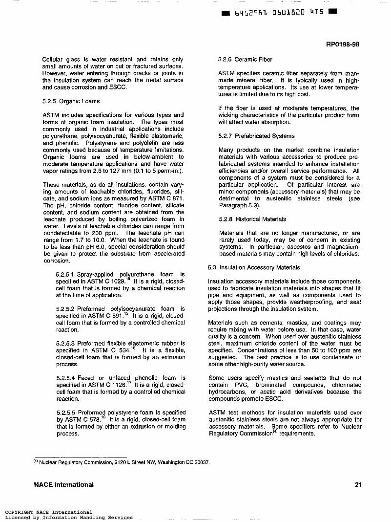
Cellular glass is water resistant and retains only small amounts of water on cut or fractured surfaces. However, water entering through cracks or joints in the insulation system can reach the metal surface and cause corrosion and ESCC.
5.2.5 Organic Foams
ASTM includes specifications for various types and forms of organic foam insulation. The types most commonly used in industrial applications include polyurethane, polyisocyanurate, flexible elastomeric, and phenolic. Polystyrene and polyolefin are less commonly used because of temperature limitations. Organic foams are used in below-ambient to moderate temperature applications and have water vapor ratings from 2.5 to 127 mm (0.1 to 5 perm-in.).
These materials, as do all insulations, contain vary- ing amounts of leachable chlorides, fluorides, sili- cate, and sodium ions as measured by ASTM C 871. The pH, chloride content, fluoride content, silicate content, and sodium content are obtained from the leachate produced by boiling pulverized foam in water. Levels of leachable chlorides can range from nondetectable to 200 ppm. The leachate pH can range from 1.7 to 10.0. When the leachate is found to be less than pH 6.0, special consideration should be given to protect the substrate from accelerated corrosion.
5.2.5.1 Spray-applied polyurethane foam is specified in ASTM C 1029.14 It is a rigid, closed- cell foam that is formed by a chemical reaction at the time of application.
5.2.5.2 Preformed polyisocyanurate foam is specified in ASTM C 591.15 It is a rigid, closed- cell foam that is formed by a controlled chemical reaction.
5.2.5.3 Preformed flexible elastomeric rubber is specified in ASTM C 534.16 It is a flexible, closed-cell foam that is formed by an extrusion process.
5.2.5.4 Faced or unfaced phenolic foam is specified in ASTM C 1 126.17 It is a rigid, closed- cell foam that is formed by a controlled chemical reaction.
5.2.5.5 Preformed polystyrene foam is specified by ASTM C 578.’* It is a rigid, closed-cell foam that is formed by either an extrusion or molding process.
5.2.6 Ceramic Fiber
ASTM specifies ceramic fiber separately from man- made mineral fiber. It is typically used in high- temperature applications. Its use at lower tempera- tures is limited due to its high cost.
If the fiber is used at moderate temperatures, the wicking characteristics of the particular product form will affect water absorption.
5.2.7 Prefabricated Systems
Many products on the market combine insulation materials with various accessories to produce pre- fabricated systems intended to enhance installation efficiencies and/or overall service performance. All components of a system must be considered for a particular application. Of particular interest are minor components (accessory materials) that may be detrimental to austenitic stainless steels (see Paragraph 5.3).
5.2.8 Historical Materials
Materials that are no longer manufactured, or are rarely used today, may be of concern in existing systems. In particular, asbestos and magnesium- based materials may contain high levels of chlorides.
5.3 Insulation Accessory Materials
Insulation accessory materials include those components used to fabricate insulation materials into shapes that fit pipe and equipment, as well as components used to apply those shapes, provide weatherproofing, and seal projections through the insulation system.
Materials such as cements, mastics, and coatings may require mixing with water before use. In that case, water quality is a concern. When used over austenitic stainless steel, maximum chloride content of the water must be specified. Concentrations of less than 50 to 1 O0 ppm are suggested. The best practice is to use condensate or some other high-purity water source.
Some users specify mastics and sealants that do not contain PVC, brominated compounds, chlorinated hydrocarbons, or acetic acid derivatives because the compounds promote ESCC.
(4) Nuclear Regulatory Commission, 2120 L Sireet NW, Washington DC 20037.
NACE International
ASTM test methods for insulation materials used over austenitic stainless steels are not always appropriate for accessory materials. Some specifiers refer to Nuclear Regulatory Commission(4) requirements.
21
COPYRIGHT NACE InternationalLicensed by Information Handling ServicesCOPYRIGHT NACE InternationalLicensed by Information Handling Services
RPO198-98
5.3.1 Cements
Cements are used to join insulation materials into useful shapes. Hydrated silicates are used with calcium silicate, perlite, and cellular glass. Water quality is a concern. Asphaltic materials are commonly used in low-temperature systems. Some asphaltics may not pass acceptance testing for use with austenitic stainless steels. Materials containing chlorinated polymers, such as PVC, are not suitable for insulating austenitic stainless steels.
5.3.2 Adhesives
Adhesives are used to bond insulation materials to equipment surfaces in some applications. Adhesives are also a component of tapes, prefabricated pipe covers, and other prefabricated systems.
Some adhesives used on adhesive tapes have been found to cause cracking of austenitic stainless steels. The most common problem has been the use of tape to temporarily position heat tracers or other insulation system components.
Adhesives used with labeling systems for identifi- cation are of concern due to the effects of chloride content and crevices.
5.3.3 Mastics and Coatings
Mastics and coatings are applied over insulation materials for weather protection and as cold service vapor barriers where metal or other jacketing is not used. Irregular shapes, such as pumps and valves, are typical applications.
Weatherability and maintenance of these materials must be considered when used to provide primary weather protection. Periodic inspection and repair of damage are necessary to maintain the usefulness of these materials.
5.3.4 Sealants and Caulks
Sealants and caulks are used to seal protrusions through insulation systems and to provide vapor barriers in below-ambient conditions.
Failure of sealant and caulking systems is a common source of water intrusion into insulation systems. Weatherability, maintenance, and suitability for the service temperature must be considered. Periodic inspection and repair of damage are necessary to maintain the usefulness of these materials.
5.3.5 Jacketing Materials
Jacketing materials are used to provide mechanical and weather protection for insulation systems.
Commonly used materials include aluminum, aluminized steel, galvanized steel, stainless steel, fiberglass-reinforced plastic, thermoplastics, rein- forced fabrics, and tape systems.
Aluminum jacketing is economical, relatively corro- sion resistant, and easy to work with, and therefore, its use is widespread. Pitting corrosion from the inside surface due to entrapped moisture and reaction with wet insulation materials is a concern. It is commonly supplied with an inner barrier of thermoplastic film and/or kraft paper. It is available with various factory-applied coatings for additional corrosion resistance. Pitting and perforation of aluminum jacketing negates its function as a weather barrier. Use of aluminum on high-temperature (above 540°C [IOOO"F]), high-alloy equipment is normally restricted due to liquid metal cracking concerns.
Stainless steel jacketing is available in types 302, 304, and 316. Because it is more expensive than aluminum jacketing, its use is limited to specialized applications such as plant atmospheres corrosive to aluminum, areas where insulation is intended to serve as fireproofing, and use on high-temperature (above 540°C [I ,OOO"F]), high-alloy equipment. The concerns previously discussed for ESCC of stainless steel equipment and piping are also a concern with stainless steel jacketing in the appropriate environ- ment or in contact with leachable chloride-containing insulation. Stainless steel jacketing is commonly supplied with an inner barrier of thermoplastic film and/or kraft paper. When stainless steel jacketing is used, it should be used in conjunction with stainless steel bands and hardware to reduce the occurrence of galvanic corrosion and, at high temperatures, LMC.
Galvanized steel or aluminized jacketing suffers from iron-oxide staining as a result of corrosion at seams, screw holes, and other edges where the zinc or aluminum is unable to provide adequate coverage. In addition, galvanized jacketing cannot be used at high temperatures greater than 370°C (700°F) as zinc is a low-melting-point metal. As with the jacket- ing materials mentioned above, galvanized and aluminized-steel jacketing is commonly supplied with an inner barrier of thermoplastic film and/or kraft paper.
Plastic materials such as fiberglass-reinforced plastic and thermoplastics are not commonly used for jacketing because of their low melting temperatures, lack of resistance to mechanical abuse and ultra- violet radiation (sunlight), and corrosion by many chemicals. These materials are only used for specialized applications and are more effective for indoor use.
22 NACE International
COPYRIGHT NACE InternationalLicensed by Information Handling ServicesCOPYRIGHT NACE InternationalLicensed by Information Handling Services

RPO198-98
Reinforced fabric jacketing is typically used for piping components where conventional insulation removable and reusable insulation covers, which are made specifically for specific equipment items and
methods are impractical.
6.1 Overview
Section 6: Inspection and Maintenance
Thermal insulation on plant process equipment creates a formidable barrier to easy inspection for corrosion damage. Unfortunately, the very presence of thermal insulation can set up corrosion problems that are completely unrelated to the product contained in the pipe or vessel.
In many instances, it is a simple task to detect and measure the effects of corrosion due to the process fluids and gases on the inside surface of piping and equipment, yet a very difficult task to detect and measure the effects of corrosion due to thermal insulation on the outside surface.
Removing all the insulation would be the ideal method for locating and evaluating CUI, but it is time-consuming and expensive. Visual inspection for evidence of moisture or corrosion will help to predict where surface corrosion threatens the piping system or equipment. At the very least, it can locate “suspect” areas for further investigation. All plant personnel can and should help with the visual inspection and then consult with the company experts.
6.2 Pre-Inspection Activities
A plan should be developed to inspect and record warning signs of CUI. It is helpful to begin with a plant or area map indicatin location of equipment. For process piping, refer to API 8 570.” The map should be used as a point of departure to prioritize, inspect, and record suspect insulation. The following list should be used in setting priorities, and a separate prioritizing checklist should be used for each item of equipment.
6.2.1.2 Does the prevailing wind contain high humidity or corrosive contaminants?
Equipment downwind of corrosive mists (e.g., cooling tower, power plant, and seashore) is more exposed to CUI factors.
6.2.1.3 Is equipment susceptible to mechanical damage?
Insulation systems bumped by tools or used as mechanical support for workers are more likely to break down and allow water entry.
6.2.2 Temperature and Materials of Construction
6.2.2.1 How susceptible is the alloy to corrosion or to cracking at operating temperatures?
The probability of material failure varies with operating temperature or range of temperature. The following are the temperature ranges of greatest concern.
6.2.2.1.1 For carbon steel, continuous process operation at temperatures between -4°C and 150°C (25°F and 300°F) or cycling above and below the dew point.
6.2.2.1.2 For type 300 series stainless steels, continuous process operation between 50°C and 150°C (120°F and 300°F) or cycling above and below the dew point.
6.2.3 Age of Equipment
6.2.3.1 How long has the equipment been in service since last insulated?
6.2.1 Location of Equipment Because CUI is an insidious problem, it is helpful to check records for when the equipment
6.2.1.1 Is it indoors or outdoors? was installed or last insulated. CUI problems are commonly found to be significant after about
Inside areas are less at risk, provided that they five years. are not near hose-down, safety shower, or fire protection deluge systems. 6.2.4 Coatings
(5’ American Petroleum Institute (API), 1220 L St. NW, Washington, DC 20005.
NACE International 23
COPYRIGHT NACE InternationalLicensed by Information Handling ServicesCOPYRIGHT NACE InternationalLicensed by Information Handling Services

RPO198-98
6.2.4.1 Is equipment coated?
Coated equipment has a better survival rate, but the type of coating used should also be con- sidered. Coatings suitable for liquid immersion service are usually specified, and guidelines for selection of protective coatings are found in Section 4. Insulated equipment that has been coated is much easier to inspect.
6.2.5 Risk Potential - Process/Business/Environ- ment/Safety/Heal t h
6.2.5.1 Are there exposed fittings?
Fixtures such as clips, nozzles, and inspection ports needing caulking are potential points for water entry. A change of design is sometimes the only solution.
6.2.5.2 What are the consequences of the leak?
In choosing the frequency of inspection, a business should consider the environmental and economic ' consequences of a leak. Also, OSHA@) CFR 1910.1 i 9: Process Safety Management2' (or similar local standards) should be used as a guide.
6.2.5.3 What is the cost of downtime for repairs or replacement? Should key items of plant equipment be inoperable for several weeks? Several months?
6.3 Visual Inspection
6.3.1 New Construction
Design and specification documents should be reviewed to make sure they are complete and correct. Adequate resources must be devoted to ensure that the design details are properly imple- mented. Visual inspection of the insulated equipment and piping in the work area should be started using the site map, the prioritizing checklist, and an inspection work sheet. Equipment designated to be coated should be checked to verify that it has been coated according to manufacturer's or owner's specifications. Suspect areas should be recorded. The following guidelines should be adhered to as CUI may occur when the following recommendations have not been followed:
(a) (b)
Keep insulation dry at all times. Keep surfaces to be insulated clean and dry.
Ensure that a full bedding coat of asphalt cutback is applied when required. Use the insulation thickness designated in the project insulation specifications. Determine whether the insulation should be single-layer or double-layer. Ensure that all joints are staggered, especially on double-layered systems. Ensure that a bedding coat has been applied between the first and second insulation layers, for systems operating below -40°C (-40°F). Do not apply the coat to the substrate. Ensure that the insulation has no gaps greater than 3 mm (0.125 in.). Replace the affected section of insulation if the gap exceeds 3 mm (0.125 in.). Do not use finishing cement to fill the gap. Use valve stem extension handles, where applicable, for insulated valves. For systems requiring a vapor barrier, ensure that the vapor barrier has been applied to the exterior of the insulation before installing the jacket. Do not use screws to secure jacketing on systems with vapor barriers. Ensure that insulation has been secured with the specified wire, bands, or tape. Ensure that all insulation terminations have end caps. Ensure that watershed angles are provided. Ensure that installed insulation is protected from rain and washdown until jacketing is installed. Ensure that the proper jacketing type and metal thickness is installed. Ensure that the jacketing is installed in watershed fashion on horizontal runs. Ensure that the bands and breather springs are the correct size and material. These are installed on the outside of the jacketing around the equipment. Ensure that the bands are turned under or caulked at the clips. Ensure that the nozzle openings and all other protrusions are flashed and caulked. Ensure that the system has been caulked. Caulking should be left beaded, not feathered. Order duplicate equipment nameplates for systems operating below 0°C (32°F). These should be banded, not screwed, to the outside of the jacketing.
6.3.2 Equipment in Service
Using the site map, the prioritizing checklist, and an inspection work sheet, inspections of the insulated
@) Occupational Safety and Health Administration (OSHA), 100 Constitution Ave. NW, Washington, DC 2021 O.
24 NACE International
COPYRIGHT NACE InternationalLicensed by Information Handling ServicesCOPYRIGHT NACE InternationalLicensed by Information Handling Services

RPO198-98
equipment and piping in the area should be conducted. Specific items of equipment that are coated should be identified. Suspect areas should be recorded. Inspection personnel should be alert to the following warning signs:
Weathered, damaged, inelastic, or missing caulking on piping, vessel heads, sidewalls, supports, and nozzles. Weathered, split, or missing mastic moisture barriers on piping and vessels, and on sidewalls, above supports, and around nodes. Punctured, torn, loose, dislodged, slipped, missing, or corroded metal jacketing. Stains, deposits, or holes in jackets and covers. Unsealed piping terminations. Gaps in jackets around pipe hangers, at the tip of vertical pipe runs, and at other protrusions such as structural stainless steel supports. Swollen or blistered insulation. Improper installation interfering with water run- Off. Mildew or moisture at insulation support rings or vacuum rings on vessels. Unprotected insulation where parts have been removed . Unsealed metal wall thickness test points. Flashing that does not shed water. Open joints in jackets from physical damage.
6.4 Nondestructive Moisture and Corrosion Detection Techniques
These techniques and devices can enhance visual inspection on any type of insulation. On pressure vessels and piping, the CUI pattern may be nonuniform, and spot nondestructive evaluation (NDE) may be misleading.
6.4.1 Delmhorst moisture meter
6.4.2 Infrared thermography
equipment must be assessed. Insulation should be removed or the corrosion should be evaluated by a suitable NDE technique. Some of the techniques are listed in Paragraph 6.4.
The following procedure should be used for assessing the damage:
6.5.1 Remove a patch of insulation, 120 to 150 cm2 (18 to 24 in.') in area, from vessels or piping greater than 61 cm (24 in.) in diameter, or a section 0.9 m (3 ft) long from piping less than 61 cm (24 in.) in diameter, where there is probable corrosion damage. Site-specific requirements must be followed when removing asbestos, respirable ceramic fiber (RCF), or non-asbestos respirable fiber (NARF) insulation.
6.5.2 When repeat inspections are to be made at the same point, use replaceable insulation plugs to close inspection holes in the insulation.
6.5.3 Examine the equipment for thick rust deposits on carbon steel and hard, crusty deposits on austenitic stainless steel. Corrosion is often found above vacuum rings and insulation support rings, above and below manways, and below breaks in top head moisture barriers.
6.5.4 If there is no corrosion and the insulation is dry, replace the insulation and seal thoroughly.
6.5.5 If there is no corrosion but the insulation is wet, remove the insulation to the point where it is completely dry. Eliminate the source of water intrusion, using proper insulation installation techniques.
6.5.6 If corrosion damage has occurred, remove all the insulation from the damaged areas. The total system must be inspected and cleaned. The damaged equipment or parts must be repaired as necessary or replaced. The metal surface must be protectively coated and reinsulated.
6.4.3 Neutron backscatter device 6.6 Equipment Inspection Methods
6.4.4 Flash radiography 6.6.1 Carbon Steel
6.4.5 Electromagnetic (eddy current)
6.4.6 Ultrasonic testing (UT) of the equipment from the inside
6.4.7 Fluoroscopic imaging of piping
6.4.8 Profile radiography
6.5 Assessment of Damage
If investigations or observations indicate wet insulation, the extent of corrosion or structural damage to the
Ultrasonic thickness and pit depth measurement techniques are usually used to determine the remaining wall thickness of pipe, tanks, pressure vessels, and other plant equipment when there is direct access to the exterior surface. Testing should be conducted using established test procedures such as those found in API 51 O," 570, and 653.2'
6.6.2 Stainless Steel
6.6.2.1 Eddy Current Inspection
NACE International 25
COPYRIGHT NACE InternationalLicensed by Information Handling ServicesCOPYRIGHT NACE InternationalLicensed by Information Handling Services

b45298L 0503825 T87 m
RPO198-98
Eddy current inspection is recommended for stainless steel surface inspection. When properly used, it is a rapid, effective method for detecting ESCC. Eddy current examination must be performed by qualified specialists.
6.6.2.2 Liquid Dye Penetrant Inspection (PT)
When eddy current examinations are not practical, liquid dye penetrant inspection is a useful procedure for ESCC detection. The metal surface must be as near ambient temperature as possible. This procedure will not be effective at an elevated temperature. The periphery of cracked areas should be examined for less obvious cracking, especially if weld repair is being considered. Only halogen-free PT materials should be used.
6.6.3 Surface Preparation and Cleaning
One effective surface cleaning procedure for PT of stainless steels involves aspirating a small amount of grit, such as No. 7 crushed flint, into a high-pressure water-blast nozzle to remove deposits (but not the brown stains occurring on stainless steel) and minimize dusting. Brown stains on stainless steel often indicate ESCC. Heavy grit blasting or sanding may smear over the cracks and decrease the effectiveness of the PT.
6.6.3.1 The stainless steel surface should be prepared for PT by one or more of the following techniques to remove surface deposits and to avoid peening shut any ESCC.
(a) Hydroblasting - Conventional abrasive blasting should not be used.
(b) Disc sanding - This can be done with coarse grit and moderate pressure. Too much pressure will force grit into cracks. Flapper sanding - This can be done with coarse grit and moderate pressure. Pencil grinding - This can be used to prepare fillet welds where a sander cannot reach.
(c)
(d)
6.6.3.2 The prepared area should be washed with water, cleaned with chloridefree solvent, and wiped dry with a lint-free cloth. Red dye penetrant should be applied by spray or brush on ambient temperature surfaces, allowing 15 min to penetrate. Excess penetrant should be wiped off with a lint-free cloth soaked in chloride- free solvent. A very thin coating of developer should be applied followed by visual inspection after at least 1 O min for indications of cracking.
6.7 Repair
The extent of damage will determine the type and amount of repair required.
Before beginning repairs, a qualified corrosion/materials specialist should be consulted to assist in assessing damage and choosing repair methods. Methods must be consistent with good practices and code requirements. Examples of repair techniques and insulation refurbish- ment practices are:
6.7.1 Replacement of equipment may be necessary if its integrity is affected by severe corrosion of carbon steel or by ESCC of austenitic stainless steel.
6.7.2 Repair of equipment that has corroded must follow the requirements of applicable codes and standards. These include the ANSI"' National Board Inspection Code (NB-23),23 API 510 for pressure vessels, API 653 for tanks, and API 570 for piping.
6.7.3 Replace deteriorated caulking with silicone caulking compounds.
6.8
6.7.4 Replace flashing around vacuum and insula- tion support rings, and clips on vessels as well, with types that direct water away.
Shutdown and Mothballing
Some severe cases of CUI have occurred during extended shutdowns or mothballing of equipment. Weather barriers deteriorate during these idle periods, and typically, no maintenance or repair is performed.
Carbon steel piping and equipment may be severely corroded at ambient temperature when mothballed. Stainless steel is susceptible to ESCC by the water- leached salts when the equipment is brought on-line aíter idle periods; however, it is not likely to corrode under insulation during storage.
When plant management is uncertain whether equipment will be used again, funds or facilities to maintain weather barriers or to move equipment indoors may not be provided. Stripping all insulation before mothballing is the most cost-effective way of storing carbon steel and stainless steel piping and equipment. As a rule, rusting of exposed carbon steel is less severe and more uniform than corrosion under wet insulation.
Stored equipment shall be abrasiveblasted, recoated, and reinsulated before use in a CUI environment.
(7) American National Standards Institute (ANSI), 11 W. 42nd St., New York, NY.
26 NACE international
COPYRIGHT NACE InternationalLicensed by Information Handling ServicesCOPYRIGHT NACE InternationalLicensed by Information Handling Services

RPO198-98
References
1. ASTM C 692 (latest revision), “Standard Test Method for Evaluating the Influence of Thermal Insulations on External Stress Corrosion Cracking Tendency of Austeni- tic Stainless Steel” (West Conshohocken, PA: ASTM).
2. W.I. Pollock and J.M. Barnhart, eds., Corrosion of Metals Under Thermal Insulation, STP 880. (West Conshohocken, PA: ASTM, 1985).
3. NACE Publication 6H189 (latest revision), “A State of-the-Art Report on Protective Coatings for Carbon Steel and Austenitic Stainless Steel Surfaces Under Thermal Insulation and Cementitious Fireproofing” (Houston, Tx: NACE).
4. F.N. Speller, Corrosion - Causes and Prevention, 2nd ed. (New York, NY: McGraw-Hill Book Co., 1935), p. 153 and Fig. 25.
5. W.G. Ashbaugh, “Corrosion of Steel and Stainless Steel Under Thermal Insulation,” in Process Industries Corrosion, eds. B.J. Moniz, W.I. Pollock (Houston, TX: NACE, 1986), p. 761.
6. ASTM C 871 (latest revision), “Standard Test Methods for Chemical Analysis of Thermal Insulation Materials for Leachable Chloride, Fluoride, Silicate, and Sodium Ions” (West Conshohocken, PA: ASTM).
7. ASTM C 795 (latest revision), “Standard Specifica- tion for Thermal Insulation for Use in Contact with Austenitic Stainless Steel” (West Conshohocken, PA: ASTM) .
8. W.G. Ashbaugh, ”External Stress Corrosion Cracking of Stainless Steel Under Thermal Insulation,” MP 4, 5 (1965): pp. 18-23.
9. ASTM C 929 (latest revision), “Standard Practice for Handling, Transporting, Shipping, Storage, Receiving, and Application of Thermal Insulation Materials For Use in Contact with Austenitic Stainless Steel“ (West Conshohocken, PA: ASTM).
10. NACE Standard RP0375 (latest revision), “Wax Coating Systems for Underground Piping Systems” (Houston, TX: NACE).
11. ASTM C 533 (latest revision), “Standard Specifica- tion for Calcium Silicate Block and Pipe Thermal Insulation” (West Conshohocken, PA: ASTM).
12. ASTM C 610 (latest revision), “Standard Specifica- tion for Molded Expanded Perlite Block and Pipe Thermal Insulation” (West Conshohocken, PA: ASTM).
13. ASTM C 552 (latest revision), “Standard Specifica- tion for Cellular Glass Thermal Insulation” (West Conshohocken, PA: ASTM).
14. ASTM C 1029 (latest revision), “Standard Specifica- tion for Spray-Applied Rigid Cellular Polyurethane Thermal Insulation” (West Conshohocken, PA: ASTM).
15. ASTM C 591 (latest revision), “Standard Specifica- tion for Unfaced Preformed Rigid Cellular Polyiso- cyanurate Thermal Insulation” (West Conshohocken, PA: ASTM) . 16. ASTM C 534 (latest revision), “Standard Specifica- tion for Preformed Flexible Elastomeric Cellular Thermal Insulation in Sheet and Tubular Form” (West Conshohocken, PA: ASTM).
17. ASTM C 1126 (latest revision), “Standard Specifica- tion for Faced or Unfaced Rigid Cellular Phenolic Thermal Insulation” (West Conshohocken, PA: ASTM).
18. ASTM C 578 (latest revision), “Standard Specifica- tion for Rigid, Cellular Polystyrene Thermal Insulation“ (West Conshohocken, PA: ASTM).
19. API Standard 570 (latest revision), “Piping Inspection Code: Inspection, Repair, Alteration, and Rerating of In- Service Piping Systems” (Washington, DC: API).
20. CFR 191 O (latest revision), “Occupational Safety and Health Standards” (Washington, DC: OSHA).
21. API Standard 510 (latest revision), “Pressure Vessel Inspection Code: Maintenance Inspection, Rating, Repair, and Alteration” (Washington, DC: API).
22. API Standard 653 (latest revision), “Tank Inspection, Repair, Alteration, and Reconstruction“ (Washington, DC: API).
23. NB-23 (latest revision), “National Board Inspection Code: Manual for Boiler and Pressure Vessel Inspectors” (New York, NY: ANSI).
NACE International 27
COPYRIGHT NACE InternationalLicensed by Information Handling ServicesCOPYRIGHT NACE InternationalLicensed by Information Handling Services

b45298L 0503827 85T W
RPO198-98
Bibliography
Ashbaugh, W.G. “ESCC of Stainless Steel under Montle, S., W.G. Ashbaugh, and J.F. Delahunt. “Problem Solving Forum.” Journal of Protective Coatings and Linings 2, 1 (1985): p. 10.
Ashbaugh, W.G. “Stress Corrosion Cracking of Process NACE Publication 6A176. “Inorganic Zinc Coatings for Immersion (Tank Lining) Service.” Houston, TX:
Thermal Insulation.” Materials Protection 4, 5 (1 965): p. 18.
Equipment.” Chemical Engineering Progress, 66, 1 O (1970): p. 44. NACE, 1976.
Delahunt, J.F. “Corrosion of Underground Insulated Pipelines.” Journal of Protective Coatings and Linings 3, 1 (1986): p. 36.
Haney, E.G. “The Zinc-Steel Potential Reversal in Cathodic Protection.” CORROSION/81, paper no. 216. Houston, T X NACE, 1981.
Mattsson, E. “The Atmospheric Corrosion Properties of Some Common Structural Metals-A Comparative Study.” CORROSION/82, plenary lecture. Houston, TX: NACE, 1982.
NACE Publication 6B161. “Zinc Filled Inorganic Coat- ings.” Houston, TX: NACE, 1961.
SSPC Publication PS 12.00. “Guide for Selecting Zinc- Rich Painting Systems.” Pittsburgh, P A SSPC, 1991.
Zinc: Its Corrosion ßesktance. New York, NY: Inter- national Lead Zinc Research Organization, Inc., 1971.
28 ISBN 1-57590-0441 NACE International
COPYRIGHT NACE InternationalLicensed by Information Handling ServicesCOPYRIGHT NACE InternationalLicensed by Information Handling Services